


ROOM AIR CONDITIONERS INSTALLATION INSTRUCTIONS
•Please read this instruction sheet completely before installing the product.
•When the power cord is wanted to replace, replacement work shall be performed by authorized personnel only.
•Installation work must be performed in accordance with national wiring standards by authorized personnel only.
more than 5cm
 1cm
1cm
1. Type "A" screw
more than 5cm
2. Installation Plate
3. Type "B" screw
4. Holder Remote-Controller
|
5. Copper pipe (Liquid side) |
|
|
6. Copper pipe (Gas side) |
|
more than |
more than |
|
10cm |
||
10cm |
||
|
||
|
7. Power supply cord(power connecting cable) |
|
more than |
8. Connecting cable(except 18K cooling only model) |
|
|
||
70cm |
|
|
|
|
Cooling & |
Model has |
t |
Le modHeating |
"Froid e |
|
included Drain Elbow |
|
|
chauffage" est |
uipÈ d'un |
|
ENGLISH
ITALIANO
P/No.: 3828A90005G

OUT-LINE OF INSTALLATION
1.The following should always be observed for safety ...................................................3
Installation works Installation Parts Required Tools
2. Installation of indoor, outdoor Unit
1) Selection of the best location ...4 |
• Installation plate |
• Level |
2) Indoor unit Installation ..............5 |
• Four type "A" screws |
• Screw driver |
|
• Connecting cable |
• Electric drill |
|
|
• Hole core drill(ø70mm) |
3. Piping and drainage of indoor unit
1) Preparation of pipings ............6 |
• Pipes: Gas side............. |
1/2", 5/8" |
|
2) Connection of pipings ...... |
7~11 |
Liquid side ......... |
1/4", 3/8" |
• For right rear piping |
|
(different depending on model No.) |
|
• For the left piping |
|
• Insulated drain hose |
|
|
|
• Insulation materials |
|
•Flaring tools set
•Specified torque wrenches
1.8kg.m, 4.2 kg.m, 5.5 kg.m,
6.6kg.m
(different depending on model No.) Spanner.........................Half union
4. Connecting pipings and the cable to outdoor unit
1) Connection of pipings to the |
• Additional drain hose |
|
outdoor unit ............................ |
12 |
(Outer Dia .....................15.5 mm) |
2) Connection of the cable .........12
•Specified torque wrenches
1.8kg.m, 4.2 kg.m, 5.5 kg.m,
6.6kg.m
(different depending on model No.)
5. Checking the drainage and connecting the cable to Indoor unit
1) Checking the drainage ..........14 |
• A glass of water |
|
2) Connecting of the cable .........15 |
• Screw driver |
|
3) Forming the pipings ...............16 |
||
|
6. |
Air Purging |
|
|
1) Air Purging ............................17 |
|
• Hexagonal wrench (4mm) |
|
2) Checking a gas-leakage ........18 |
|
• Gas-leak detector |
|
7. |
Maximum length of pipe and freon extra change...........................................................19 |
||
8. |
Test running |
|
|
1) Connection of power supply |
• Tow type "B" screws |
• Owner's manual |
|
|
...............................................20 |
|
• Thermometer |
|
|
|
|
2) Evaluation performance
..............................................20
2 ENGLISH

1. The following should be always be observed for safety
• Please report to or take consent by the supply authority before connection to the system. |
ENGLISH |
|
|
||
• Be sure to read "THE FOLLOWING SHOULD ALWAYS BE OBSERVED FOR SAFETY" before installing |
|
|
the air conditioner. |
|
|
• Be sure to observe the cautions specified here as they include important items related to safety. |
|
|
• The indications and meanings are as follows. |
|
|
WARNING |
Could lead to death, serious injury, etc. |
|
CAUTION Could lead to serious injury in particular environments when operated incorrectly.
•After reading this manual, be sure to keep it together with the instruction manual in a handy place on the customer's site.
WARNING
Do not install it yourself (customer).
•Incomplete installation could cause injury due to fire, electric shock, the unit falling or a leakage of water. Consult the dealer from whom you purchased the unit or special installer.
Perform the installation securely referring to the installation manual.
•Incomplete installation could cause a personal injury due to fire, electric shock, the unit falling or a leakage of water.
Install the unit securely in a place which can bear the weight of the unit.
•When installed in an insufficient strong place, the unit could fall causing injured.
Perform electrical work according to the installation manual and be sure to use an exclusive circuit.
•If the capacity of the power circuit is insufficient or there is incomplete electrical work, it could result in a fire or an electric shock.
Use the specified wires to connect the indoor and outdoor units securely and attach the wires firmly to the terminal board connecting sections so the stress of the wires is not applied to the sections.
• Incomplete connecting and fixing could cause fire.
Check that the refrigerant gas due not leak after installation is completed.
Attach the electrical part cover to the indoor unit and the service panel to the outdoor unit securely.
•If the electrical part cover if the indoor unit and/or the service panel if the outdoor unit are not attached securely, it could result in a fire or electric shock due to dust, water, etc.
Be sure to use the part provided or specified parts for the installation work.
•The use of defective parts could cause an injury or leakage of water due to a fire, electric shock, the unit falling, etc.
CAUTION
Perform grounding
•Do not connect the ground wire to a gas pipe, water pipe arrester or telephone ground wire. Defective grounding could cause an electric shock.
Do not install the unit in a place where an inflammable gas leaks.
•If gas leaks and accumulates in the area surrounding the unit, it could cause an explosion.
Perform the drainage/piping work securely according to the installation manual.
•If there is a defect in the drainage/piping work, water could drop from the unit and household goods could be wet and damaged.
ENGLISH 3
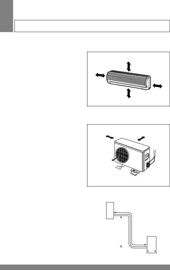
2.Installation of Indoor, Outdoor unit
1)Selection of the best location
1. Indoor unit
•There should not be any heat source or steam near the unit.
•There should not be any obstacles to prevent the air circulation.
•A place where air circulation in the room will be good.
•A place where drainage can be easily obtained.
•A place where noise prevention is taken into consideration.
•Do not install the unit near the door way.
•Ensure the spaces indicated by arrows from the wall, ceiling, fence, or other obstacles.
More than |
More than 5 cm |
|
5 cm |
||
|
||
|
More than |
|
|
5 cm |
|
More than eye-level |
|
2.Outdoor unit
•If an awning is built over the unit to prevent direct sunlight or rain exposure, be careful that heat radiation from the condenser is not restricted.
•There should not be any animals or plants which could be affected by hot air discharged.
•Ensure the spaces indicated by arrows from the wall, ceiling, fence, or other obstacles.
More than 10 cm |
More than 10 cm |
More than 70 cm 
3.Piping length and the elevation |
|
|
|
|
|
|
|
|
|||
|
|
|
|
|
|
Indoor unit |
|||||
MODEL |
Pipe Size |
Max. |
Max. |
|
|||||||
|
|
length |
Elevation |
|
|
|
|
|
|
|
|
|
GAS |
LIQUID |
|
|
|
|
|
|
|
||
|
A (m) |
B (m) |
|
|
|
|
|
|
|
||
|
|
|
|
|
|
|
|
|
A |
||
18K |
1/2" |
1/4" |
30 |
15 |
|
|
|
|
|||
|
|
|
|
|
|
|
B |
|
|
||
24K |
5/8" |
1/4" |
30 |
15 |
|
|
|
|
|
Outdoor |
|
|
|
|
|
|
|
||||||
|
|
|
|
|
|
|
|
|
|
|
|
|
|
|
|
|
|
|
|
|
|
|
unit |
|
|
|
|
|
|
|
|
|
|
|
|
|
|
|
|
|
|
|
|
|
|
|
|
|
|
|
|
|
|
|
|
|
|
|
|
4 ENGLISH
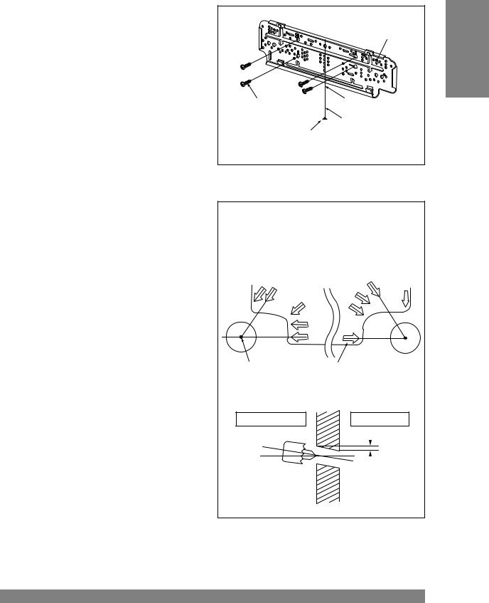
2) Indoor Unit Installation
The mounting wall should be strong and solid enough to protect it from the vibration.
1.Mount the installation plate on the wall with four Type "A" screws.
(if mounting the unit on the concrete wall, consider using anchor bolts.)
•Always mount the Installation plate horizontally by aligning the marking-off line by means of the thread and a level.
Installation Plate
Type "A" screw |
marking-off line |
Thread
Weight
2.Drill the piping hole with 70mm dia. holecore drill.
•For right rear piping and left rear piping, draw a line in the direction of the arrow marked "D". The meeting point of the two lines is the center of the hole.
•Drill the piping hole with a ø70mm hole core drill. Drill the piping hole at either the right or the left with the hole slightly slanted to the outdoor side.
The lower left and right side of Installation Plate
Left rear piping |
Right rear piping |
|
C |
B,D |
D |
A,B,C |
||
|
|
C |
|
A |
A,B |
|
C |
|
|
A,B,D |
D |
Hole Center |
|
ø70mm |
Installation plate |
||
|
WALL |
|
Indoor |
Outdoor |
|
5-7mm
ENGLISH
ENGLISH 5
3. Piping and Drainage of Indoor Unit
1) Preperation of Pipings
1.Cut the pipes and the cable.
•Use the accessory piping kit or the pipes purchased locally.
•Measure the distance between the indoor and the outdoor unit.
•Cut the pipes a little longer than measured distance.
•Cut the cable 1.5m longer than the length of the pipe.
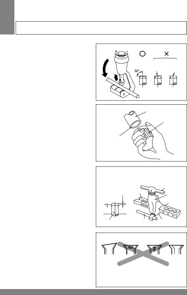
2.Remove burrs.
•Remove burrs from cut edges of pipes.
•Turn the pipe end toward down to avoid the metal powder entering the pipe.
Caution:
If burrs are not removed, they may cause a gas leakage.
Pipe cutter
Slanted Rough
Pipe
Reamer
Point down
3.Flaring the pipes.
•Insert the flare nuts, mounted on the connection ports of both indoor and outdoor unit, onto the copper pipes. Some gas may leak, when the flare nuts are removed from the indoor unit, as some gas is charged to prevent the inside of the pipe from rusting.
•Fit the copper pipe end into the Bar of flare tool about 0.5~1.0mm higher. (See illustration)
•Flare the pipe ends.
"A"; ø15.88 mm (5/8") |
0~1.0 mm |
ø12.7 mm (1/2") |
0~0.5 mm |
ø9.52 mm (3/8") |
0~0.5 mm |
ø6.35 mm (1/4") |
0~0.5 mm |
|
|
|
Handle |
|
|
Bar |
Yoke |
|
"A" |
|
|
Bar |
|
Cone |
|
|
|
|
|
Copper pipe |
Clamp handle |
Red arrow mark |
|
|
|
|
|
4.Tape the flaring portion to protect it from the dust or damages.
= Improper flaring =
Inclined |
Surface |
Cracked |
Uneven |
|
damaged |
|
thickness |
When properly flared, the internal surface of the flare will evenly shine and be of even thickness. After the flare part comes into contact with the connectors, carefully check the flare finish.
6 ENGLISH
 Loading...