


|
|
|
E N |
||||||
CRD-8400B/CRD-8400C CD-ROM DRIVE |
|
|
|
D |
|
|
|
||
|
|
|
|
|
|
||||
|
|
|
|
|
|
|
CH01 |
||
|
|
|
|
|
|
|
|
||
|
|
|
|
|
|
|
|
||
|
|
|
|
|
|
|
|
|
|
|
|
|
|
|
|||||
English.......Page E-2 ~ E-14 |
|
CLASS 1 |
LASER PRODUCT |
||||||
|
|
KLASSE 1 |
LASER PRODUKT |
||||||
|
|||||||||
|
|
LUOKAN 1 |
LASER LAITE |
||||||
|
|
||||||||
Deutsch.....Seite D-1 ~ D-13 |
|
KLASS 1 |
LASER APPARAT |
||||||
|
|
|
|
|
|
|
|
|
|
Français.....Page F-1 ~ F-13
Italiano..........Page I-1 ~ I-13
Spanish......Página S-1 ~ S-13
Copyright© 1997 LG Electronics Inc.
LG Electronics USA, Inc.
1000 Sylvan Ave.
Englewood Cliffs, NJ 07632
LG Electronics U. K. Ltd,
LG House,
264 Bath Road,
Slough,
Berks. SL1 4DT
LG Electronics Deutschland GmbH
Jakob Kaiser Straße 12
47877 Willich 1
GERMANY
LG Goldstar France SARL 12, RUE LECH WALESA BAT.B
77322 LOGNES MARNE LA VALLEE CEDEX 2 FRANCH
CD-ROM DRIVE
MODEL : CRD-8400B/CRD-8400C
OWNER’S MANUAL
BEDIENUNGSHANDBUCH
MODE D’EMPLOI
MANUALE D’USO
MANUAL DE USUARIO
To enjoy fully all the features and functions of your CD-ROM Drive,
Please read this Owner’s Manual carefully and completely.
.......English |
Page E-2 ~ E-14 |
||
|
|
||
Deutsch..... |
Seite D-1 ~ D-13 |
||
|
|
||
Français..... |
Page F-1 ~ F-13 |
||
|
|
|
|
Italiano.......... |
|
Page I-1 ~ I-13 |
|
|
|
||
Spanish...... |
Página S-1 ~ S-13 |
||
|
|
|
|
|
|
|
|
|
|
Printed in Korea |
|
P/NO : 3828HM1013E |
|||
(M-D) |
|||
|
|
||

English
CAUTION: The laser used in the CD-ROM drive can damage your eyes.
Do not attempt to open the cover.
To reduce the risk of electric shock, do not remove cover (or back).
No user-serviceable parts inside.
Refer servicing to qualified service personnel.
COMPACT
This unit uses CD-ROM discs marked with this symbol:
Use of controls or performance of procedures other than those specified herein may result in hazardous radiation exposure.
PRODUCT COMPLIES WITH DHHS
RULES 21 C.F.R. SUB-CHAPTER J,
IN EFFECT AT THE DATE OF MANUFACTURE.
WARNING: To reduce the risk of fire or electric shock,
do not expose this appliance to rain or moisture.
Industry Canada requirement
This class B digital apparatus meets all requirements of the Canadian Interference-Causing Equipment Regulations.
Cet appareil numérique de la classe B respecte toutes les exigences du Règlement sur le matériel brouilleur du Canada.
FCC COMPLIANCE STATEMENT
Note : This equipment has been tested and found to comply with the limits for a Class B digital device, pursuant to Part 15 of the FCC Rules.
These limits are designed to provide reasonable protection against harmful interference in a residential installation. This equipment generates, uses, and can radiate radio frequency energy and, if not installed and used in accordance with the instructions, may cause harmful interference to radio communications. However, there is no guarantee that interference will not occur in a particular installation. If this equipment does cause harmful interference to radio or television reception, which can be determined by turning the equipment off and on, the user is encouraged to try to correct the interference by one or more of the following measures:
-Reorient or relocate the receiving antenna.
-Increase the separation between the equipment and receiver.
-Connect the equipment into an outlet on a circuit different from that to which the receiver is connected.
-Consult the dealer or an Authorized Service Center for help.
•FCC WARNING
Changes or modifications not expressly approved by the party responsible for compliance could void the user’s authority to operate the equipment.
•This CD-ROM Drive is for use only with UL listed personal computers that have installation instructions detailing user installation of card cage accessory.
E-2

FEATURES
FEATURES
■E-IDE interface
■75ms Random access time
■Multimedia PC compatible
■Photo CD multisession support
■Small CPU bandwidth (MPC spec.)
■40X-speed Max 6000KB/sec data transfer rate
■Intelligent 128KB data buffering system
■Horizontal/Vertical mounting support
■Tray Loading system without caddy
■Designed for internal mounting
■Emergency Eject Support
■Easy audio CD control button support
■Supports Windows 95 Plug and Play ATAPI protocol
SYSTEM REQUIREMENTS
An IBM PC or compatible with the following system components:
■ IBM Compatible 486SX or above
(With PIO mode 4 support recommended)
■A Minimum of 640K memory
■Floppy disk drive (3 1/2 inch)
■MS-DOS version 3.1 or greater
■An open, front-facing, half-height drive bay.
■An existing IDE controller in your PC with an available cable connector or a new IDE controller that you will install.
SUPPLIED ACCESSORIES
Item |
|
Quantity |
|
|
|
Owner’s Manual |
|
1 |
|
|
|
Setup diskette |
|
1 |
|
|
|
Audio Cable |
|
1 |
|
|
|
|
E-3 |
|

LOCATION AND FUNCTION OF CONTROLS
COMPACT |
1 |
2 |
3 |
4 |
5 |
6 |
7 |
Figure 1. Front View
FRONT VIEW
1Headphone Jack
3.5mm jack for monitoring the audio signal from audio CDs.
2Headphone Volume Control
Adjusts the headphone sound level.
3Disc Drawer
Accepts a CD-ROM disc on its tray.
4Busy Indicator
The Busy Indicator lights during initialization and data-read operations.
5Emergency Eject Hole
Insert a paper clip here to eject the drawer manually or when there is no power.
6Play/Skip Button
When an Audio CD is in the Disc Drawer, pressing this button will start playing audio CDs from the first track. If an audio CD is playing, pressing this button will skip to the next track.
7Open/Close/Stop Button
This button is pressed to open or close the CD tray.
If an audio CD is playing, pressing this button will stop it, and pressing it again will open the tray.
E-4
|
|
|
|
|
|
|
|
|
|
|
|
|
|
|
|
|
|
|
|
|
|
|
|
|
|
|
|
|
|
|
|
|
|
|
|
|
|
|
|
|
|
|
|
|
|
|
|
|
|
|
|
|
|
|
|
|
|
|
|
|
|
|
|
|
|
|
|
|
|
|
|
|
|
|
|
|
|
|
|
|
|
|
|
|
|
|
|
|
|
|
|
|
|
|
|
DIGITAL |
|
|
ANALOG |
|
INTERFACE |
|
POWER |
|
|||||||||
|
AUDIO |
|
|
AUDIO |
|
|
|
|||||||||||
|
|
|
|
|
|
|
|
|
|
|
+5 |
GND +12 |
|
|||||
|
|
D G |
R G L C S M |
39 |
|
|
||||||||||||
|
|
|
1 |
|
|
|
|
|
|
|||||||||
|
|
|
|
|
|
|
S L A |
40 |
|
|
2 |
|
|
|
|
|
|
|
|
|
|
|
|
|
|
|
|
|
|
|
|
|
|
|
|
|
|
|
|
|
|
|
|
|
|
|
|
|
|
|
|
|
|
|
|
|
|
|
|
|
|
|
|
|
|
|
|
|
|
|
|
|
|
|
|
|
|
|
|
|
|
|
|
|
|
|
|
|
|
|
|
|
|
|
|
|
|
|
|
|
|
|
|
|
|
|
|
|
|
|
|
|
|
|
|
|
|
|
|
|
|
|
|
|
|
|
|
|
|
|
|
|
|
|
|
|
|
|
|
|
|
|
|
|
|
|
|
|
|
|
|
|
|
|
|
|
|
|
|
|
|
|
|
|
|
|
|
|
|
|
1 |
2 |
3 |
4 |
5 |
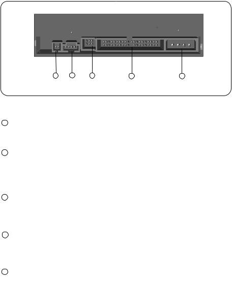
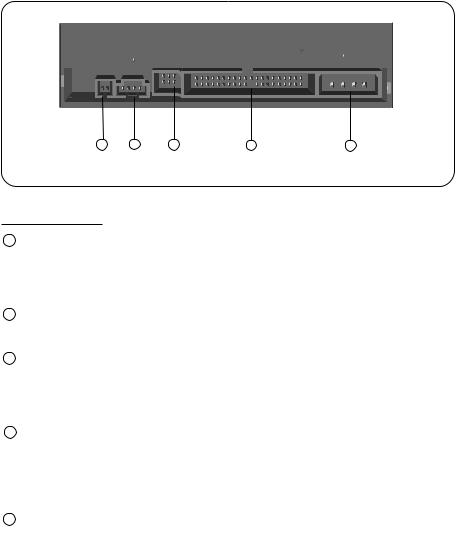
Figure 2. Back View
BACK VIEW
1Digital Audio Output Connector
This is a digital audio output connector or Video CD output connector. You can connect this to the digital audio system or Video CD Board.
2Analog Audio Output Connector
The Audio Output Connector connects to a sound card.
The supplied audio cable is a SoundBlaster® type cable. If you have a different sound card, you will need to contact the sound card manufacturer to obtain the proper cable for that card.
3Master / Slave / CSEL Jumper
These three jumpers are used to set the CD-ROM Drive to either a Master, Slave, or CSEL drive.
Refer to section HARDWARE INSTALLATION.
4Interface Connector
This 40-pin connector is used to transfer and control signals between the CD-ROM Drive and your PC.
Connect the 40-pin IDE cable in your PC to this connector.
5Power-in Connector
Attach a power cable from the computer to this connector.
E-5

HARDWARE INSTALLATION
This section describes how to install your CD-ROM drive into your computer.
WARNING:
To protect the CD-ROM Drive, your computer, and peripheral devices from damage, turn off their power before installing the drive.
Note: If you are not comfortable about opening your PC and attempting the CD-ROM drive installation, many local computer shops can perform this service for a reasonable cost.
This installation assumes you have a PC with an available connector on an IDE interface cable. If your PC has an IDE hard drive, there is usually an available connector in the middle of the same cable that attaches from the motherboard (or controller card) IDE connector to the hard drive. If the last sentence does not describe your system, you may need to purchase an IDE controller card to install this CD-ROM drive. Inspecting and knowing your PC system will make your installation easier and less time consuming.
A final note before installation: The cable connecting to your floppy disk drive is not an IDE cable. Do not attempt to attach the CD-ROM drive to this cable.
If the CD-ROM drive is to be connected to the same cable as the hard drive, be sure that the hard drive is set as master. Hard drives can be set as single, master, or slave. Check your hard drive owner’s manual or contact the hard drive manufacturer for correct jumper settings.
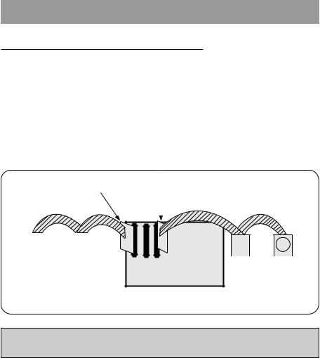
SETTING MASTER / SLAVE JUMPER
*You will see three pairs of pins and a jumper (cap) at the back of the CD-ROM drive. This jumper is used to set the CD-ROM Drive as a CSEL, MASTER, or SLAVE device in your PC. Examples of how the jumper can be placed are shown in Figure 3 below.
|
|
Note : The jumper is always |
|
|
placed vertically, |
|
|
NEVER SIDEWAYS! |
CSEL |
SLAVE MASTER |
|
mode |
mode mode |
CD - ROM drive) |
|
(default) |
|
Figure 3. Setting MASTER / SLAVE Jumper
*Move the jumper (clip on one pair of pins) from its default factory position (SLAVE), to CSEL or MASTER as needed (see the following description for the setup that matches your system), using the above diagram to place the jumper.
E-6

WHEN USING A PRIMARY IDE CONTROLLER
Most PCs provide one IDE cable to support two devices (one for hard disk, the other for a second hard disk or a CD-ROM drive). This IDE cable originates either on the motherboard or on a controller card. This controller is termed the primary IDE controller, and the hard disk attached that contains the operating system for boot-up is set up as the Primary Master. Your CD-ROM drive should be set to the Slave mode.
Hard Disk Controller Card
(This card may be a connector on the Motherboard)
Primary IDE Channel
|
|
|
|
|
|
|
|
|
|
|
|
|
|
|
|
|
|
|
|
|
|
|
|
|
|
|
|
|
|
|
|
|
Primary Slave |
Primary Master |
||||
Card Slot |
||||||||||||
|
|
|
|
|
|
|
(Hard Disk or |
|
(Hard Disk for |
|||
|
|
|
|
|
|
|
CD-ROM Drive) |
|
Boot-up) |
|||
|
|
|
Motherboard |
|
|
|
|
|
|
|||
Figure 4. Primary Controller system Configuration
Note:
Many older 1X and 2X CD-ROM drives used a 40 pin controller card that were not IDE compatible. These were proprietary interface cards for use with a particular model CD-ROM Drive. Many older Sony, Panasonic, and Mitsumi drives used 40 pin proprietary interface cards. If you are upgrading from an older CD-ROM drive, your new CD-ROM will not work on a proprietary interface card. You will need to buy a secondary IDE controller card.
E-7
WHEN USING A SECONDARY CONTROLLER
*If your PC has an additional IDE controller on the motherboard or on a system slot, each IDE device connected to the secondary IDE controller must also be set to the Master or Slave mode. If you are connecting your CD-ROM drive to a secondary IDE card, and it is the 1st device you are connecting to it, then set the CD-ROM jumper to the Master position. If it is the 2nd device, set the CD-ROM jumper to the Slave position.
*Depending on the IDE card and whether the CD-ROM drive is a master or slave unit, the diagram below represents the different ways in which the CD-ROM may be configured in your PC. The table below the diagram shows the possible Jumper placements that would correspond to each of the different configurations shown.
|
|
Secondary IDE |
|
|
|
|
||
|
|
Controller CARD |
Hard Disk Controller Card |
|||||
|
|
|
|
|
(This card may be a connector on the Motherboard) |
|||
Secondary IDE Channel |
|
|
|
Primary IDE Channel |
||||
|
|
|
|
|
|
|
|
|
|
|
|
|
|
|
|
|
|
|
|
|
|
|
|
|
|
|
|
|
|
|
|
|
|
|
|
|
|
|
|
|
|
|
|
|
Secondary Master |
Secondary Slave |
|
|
|
|
|
|
|
|
Card Slot |
Primary Slave |
Primary Master |
|||||||
(Hard Disk or |
(Hard Disk or |
||||||||
|
(Hard Disk or |
(Hard Disk for |
|||||||
CD-ROM Drive) |
CD-ROM Drive) |
|
|||||||
|
CD-ROM Drive) |
|
Boot-up) |
||||||
|
|
|
|
||||||
|
|
Motherboard |
|
|
|
|
|
|
|
Figure 5. Possible System Configuration
If you have the system with two IDE channels (in the case of an enhanced IDE PC), do not install an IDE controller card in your system.
IDE Controller |
CD-ROM Connection |
Jumper Placement |
|
|
|
Primary (1st IDE card) |
Slave(Hard disk is Master) |
SLAVE (default) |
Secondary (2nd IDE card) |
Master(1st device on 2nd IDE Card) |
MASTER |
Secondary (2nd IDE card) |
Slave(2nd device on 2nd IDE Card) |
SLAVE (default) |
|
|
|
PC Manual says use CSEL |
|
CSEL |
|
|
|
E-8

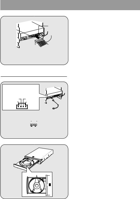
MOUNTING THE CD-ROM DRIVE
unplug your comperipheral devices
.
cover from your
front panel from an height slot.
Figure 6. Removing the Floppy Disk Drive and the Blanking plate
Figure 7. Mounting the Drive
Pin assignment
The pin assignment of the power-in connector is as follows:
5V DC |
12V DC |
GND
Power supply connector (4-pin connection cable)
Figure 8. Connecting the Power
Supply Cable
Step 4. Slide the CD-ROM drive into the half-height slot, and secure the drive in place with screws and brackets.
Note: If there is too much space between the sides of the drive and the drive bay, you may need to install spacer brackets, available at your local computer store.
Step 5. Push the power supply cable connector firmly into the power in connector.
E-9
Interface |
Pin 1 |
connector |
|
Red-edge
IDE Cable
Figure 9. Connecting the IDE Cable
to the Interface Connector
Pin assignment |
|
|
The pin assignment of the |
|
|
audio output connector is |
|
|
as follows. |
|
|
GND |
GND |
|
R-Channel |
L-Channel |
Audio |
|
to Audio |
|
|
Cable |
|
|
Equipment |
|
|
|
|
|
(sound card) |
|
* Pin assignment of the audio cable
GND |
|
|
|
|
|
GND |
L-Channel |
|
|
|
|
R-Channel |
|
|
|
|
|
|
|
|
Figure 10. Connecting an Audio Cable
to the Audio Output Connector
Disc Hooks
Connect the 40-pin IDE Cable to the back of the CD-ROM Drive. Please make sure that the red edge of the IDE Cable is connected to Pin 1 on the CD-ROM Drive.
If you want to connect audio equipment or a sound card to the CD-ROM drive, use an audio cable to connect the drive to the sound device.
Note: This CD-ROM Drive can be used vertically.
•To use the drive vertically, open the drawer and put a disc on to the 3 disc hooks. Use only standard 12cm discs.
•Do not touch the unlabeled side of the disc.
E-10
SOFTWARE SET UP
This section covers installation and setup for several operating systems. Read the entire section and select the part for your operating system.
THE SET UP PROCESS
The INSTALL program performs the following functions.
*Allows the user to select the target disk drive where CD-ROM device driver files will be set-up.
*Unless modified by the user, the INSTALL program searches the target disk for directory(\CDROM); if it is not found, the directory(\CDROM) is created.
*Copies the CD-ROM device driver file named GSCDROM.SYS, the Microsoft CD-ROM Extension file named MSCDEX.EXE, and the utility files to the specified directory.
*Modifies your CONFIG.SYS file to list the location and name of the device driver.
*Modifies your AUTOEXEC.BAT file to load MSCDEX.
*Terminates and returns control to the user.
LIST OF FILES TO BE INSTALLED IN YOUR PC
MSCDEX.EXE |
Microsoft MS-DOS CD-ROM Extension software, which |
|
enables the computer to access the CD-ROM drive. |
GSCDROM.SYS |
CD-ROM device driver. |
EJECT.EXE |
Software eject program which can eject the CD tray. |
CLOSE.EXE |
Software close program which can close the CD tray. |
RUNNING THE INSTALL PROGRAM (DOS INSTALLATION)
Step 1. Insert the CD-ROM device driver install diskette into the appropriate drive.
Step 2. Go to the floppy drive by typing A: or B: at the DOS prompt, as appropriate.
Step 3. Type the word INSTALL and press [ENTER].
Step 4. The INSTALL program will begin loading. When loading is complete, the INSTALL program identification will appear on the screen.
Step.5. Follow the instructions on the screen.
Step 6. If you specify the path information during the installation, the install program will copy the CD-ROM device driver file named GSCDROM.SYS, the Microsoft CD-ROM Extension file named MSCDEX.EXE and the utility files to the specified directory, and modify your CONFIG.SYS file and AUTOEXEC.BAT file.
Step 7. When the installation is completed, remove the diskette, and reboot your PC.
E-11

CD-ROM EXTENSION PROGRAM MSCDEX. EXE OPTIONS
There are several options that are set for the Microsoft CD Extension program. Generally, these settings do not have to be changed for the CD-ROM drive to work, so these options are needed no further. However, you may decide to change the MSCDEX option settings depending on your operating environment.
These options are explained below:
PARAMETER |
DESCRIPTION |
|
|
|
|
|
Tells MSCDEX.EXE what the device driver’s name is |
|
/D (Device Name) |
(must be same as was used in “/D:” expression of |
|
|
“DEVICE=” line in CONFIG.SYS file) |
|
|
|
|
/E |
Tells MSCDEX.EXE to use expanded memory |
|
|
|
|
/L: (Device Name) |
Indicates the drive letter to be assigned to the CD-ROM |
|
drive |
||
|
||
|
|
|
/M: (Value) |
Tells MSCDEX.EXE how much memory to allocated for |
|
caching. Default is 10 (represents 10 kilobytes). |
||
|
||
|
|
|
/V |
Provides memory usage statistics, such as how much |
|
memory is used by buffers, resident data, and resident |
||
|
code. |
|
|
|
ATAPI Installation (Windows 98/95 and others)
*For Windows 98/95 installation, do not use the installation diskette supplied. This CD-ROM drive is Windows 98/95, Windows NT 3.5, and OS/2 Warp compatible, generally utilizing the generic software drivers supplied with those operating systems Below is the example installing the driver for Windows 95. For other operating systems, try looking for either a LG Electronics or Goldstar IDE CD-ROM drive software driver. If none is found, try selecting one of the device drivers for
Non-listed IDE CD-ROM .
*You may also look in the software library on our website at www.LGEservice.com.
(For Windows 95)
1.Install the CD-ROM drive in your PC as described in this manual.
2.Power up your PC. Upon starting Windows 95, it might automatically detect the new CD-ROM drive and load the driver software for it. If not, proceed to the next step.
3.In Windows 95, Click on the Start button. Click on the Settings button. Click on the Control Panel button. Double-Click on the Add New Hardware icon. Follow the instructions for the computer to search your system for new hardware. It will locate the CD-ROM drive and load the generic driver.
E-12

INSTALLATION, USAGE AND HANDLING PRECAUTIONS
■ Installation
Avoid placing the drive in a location subject to :
-high humidity
-high temperature
-mechanical vibration
-direct sunlight
■Operation
-During operation, excessive vibration or a sudden jolt to the drive may cause a malfunction.
-Avoid exposing the drive to sudden changes in temperature. This may cause condensation to collect inside the drive.
■Transportation
-Always remove the disc before moving the drive.
TROUBLESHOOTING
*When the CD-ROM drive does not work with the hard disk drive in primary IDE channel.
(SOLUTION)
1.Check the CD-ROM drive Master/Slave Jumper setting. The CD-ROM drive must be set to the Slave mode.
2.Check to be sure your hard disk Interface type is IDE type.
3.Check your hard disk Master/Slave Jumper setting.
Some old-version IDE type hard disks were set to Master Only mode.
In that case, contact your hard disk company and change your hard disk jumper setting to master mode.
4.If the CD-ROM drive does not work with above methods, you may need a secondary IDE card. If you use the secondary IDE card, you should set the CD-ROM drive jumper to the master mode if the CD-ROM drive is the first device you are connecting to the secondary IDE card.
* When the CD-ROM drive does not install in OS/2 warp.
(SOLUTION)
1. Select NON-LISTED IDE CD.
* CD-ROM drive is not present in Windows 3.1 or 3.11 or DOSSHELL.
(SOLUTION)
1. When the WTN or DOSSHELL command lines are present in your AUTOEXEC.BAT, make sure that the MSCDEX.EXE command line appears before the WIN or the DOSSHELL command lines.
NOTE : For more information, consult the README.TXT file of the supplied Setup Diskette.
E-13

SPECIFICATIONS
General
Data Capacity |
553 Mbytes (mode 1), 635 Mbytes (mode 2) |
Disc Diameter |
12 cm / 8 cm |
Rotational Speed |
8,750 rpm |
|
|
Performance
Interface |
E-IDE |
Supported System |
IBM PC-AT or Compatible |
Transfer rate |
Sustained Data Transfer Rate = Max 6000Kbytes/sec |
Access Time |
Random 75 ms (Typical) |
MTBF |
125,000 Power On Hours (Duty Cycle 10%) |
Buffer size |
128 Kbytes |
User Data/Block |
2,048 bytes/block (Mode1 & Mode2 Form1) |
|
2,340, 2,336 bytes/block (Mode2) |
|
2,324 bytes/block (Mode2 Form2) |
|
2,352 bytes/block (CD-DA) |
Supported Disc |
CD-DA, CD-ROM, CD-ROM XA-READY, Photo-CD |
|
CD-Plus/CD-Extra, CD-RW |
|
|
Audio Specifications
Frequency Response |
20 Hz - 20 KHz +3 dB |
|
S / N Ratio |
85 dB |
|
THD |
0.05 % at 1 KHz |
|
Channel Separation |
80 dB at 1 KHz |
|
Headphone Level |
0.60 |
Vrms (33Ω ) |
Line Output Level |
0.60 |
Vrms + 10% (47kΩ ) |
Line Output Jack |
4 Pin terminal (Rear) |
|
Headphone Jack |
ø 3.5 mm (Front) |
|
|
|
|
Environment
Temperature |
5 - 45 °C |
|
|
Power Requirements
12 V + 5% |
0.9A (Maximum) |
|
Ripple < 100m Vpp |
||
|
||
5 V + 5% |
1.5A (Maximum) |
|
Ripple < 100m Vpp |
||
|
||
|
|
NOTE: Specifications are subject to change without notice for improvement.
E-14

Internet Address :
http :// www. LGEservice.com
CD-ROM LIMITED WARRANTY
LG Electronics U.S.A., Inc. will repair or at its option replace, without charge, your product which proves to be defective in material or workmanship under normal use, during the warranty period listed below from the data of original purchase. This warranty is good only to the original purchaser of the product during the warranty period as long as it is in the U.S. including Alaska, Hawaii, and U.S. Territories.
WARRANTY PERIOD
MODEL # |
LABOR |
PARTS |
CRD-8400B/ |
1 Year |
1 Year |
CRD-8400C |
|
|
HOW SERVICE IS HANDLED
If the unit is defective, a replacement* will be sent by 2-day air for the first year.
After one year, repair or a 2-day swap at a fixed labor charge. For service, please call 1-800-243-0000 (Mon.~Fri. 7AM~7PM CST)
No other express warranty is applicable to this product. THE DURATION OF ANY IMPLIED WARRANTIES, INCLUDING THE IMPLIED WARRANTY OF MERCHANTABILITY, IS LIMITED TO THE DURATION OF THE EXPRESS WARRANTY HEREIN. LG ELECTRONICS U.S.A., INC. SHALL NOT BE LIABLE FOR THE LOSS OF THE USE OF THE PRODUCT, INCONVENIENCE, LOSS OR ANY OTHER DAMAGES, DIRECT OR CONSEQUENTIAL, ARISING OUT OF THE USE OF, OR INABILITY TO USE, THIS PRODUCT OR FOR ANY BREACH OF ANY EXPRESS OR IMPLIED WARRANTY, INCLUDING THE IMPLIED WARRANTY OF MERCHANTABILITY APPLICABLE TO THIS PRODUCT.
Some states do not allow the exclusion or limitation of incidental or consequential damages or limitations on how long an implied warranty lasts; so these limitations or exclusions may not apply to you. This warranty gives you specific legal rights and you may also have other rights which vary from state to state.
THE ABOVE WARRANTY DOES NOT APPLY:
1.To damages or problems which result from delivery or improper installation.
2.To damages or problems which result from misuse, abuse, accident, alteration, or incorrect electrical current or voltage.
3.To service calls which do not involve defective workmanship or material and explaining the operation of the unit.
Therefore these costs are paid by the consumer.
CUSTOMER ASSISTANCE NUMBERS:
To Prove Warranty Coverage: |
|
Retain your Sales Receipt to prove date of purchase. |
||
|
||||
|
|
|
|
Copy of your Sales Receipt must be submitted at the time |
|
|
|
|
|
|
|
|
|
warranty service is provided. |
To Obtain Product, Customer, |
|
|
Call 1-800-243-0000 24 hrs/7 days |
|
|
|
|||
or Service Assistance: |
|
Push appropriate menu code. |
||
For Exchange Service: |
|
|
Call 1-800-243-0000 (Mon~Fri 8am~5pm CST) |
|
|
|
|||
|
|
|
|
Push appropriate menu code. |
*Replacement is a factory-reconditioned unit. Free replacement applies only within the initial one-year period. Factory-reconditioned units are available at a low, fixed cost after the oneyear warranty expires.
CD-ROM LAUFWERK
Deutsch
Um alle Möglichkeiten und Funktionen lhres CD-ROM Laufwerkes voll ausschöpfen zu können, lesen Sie bitte dieses Bedienungshandbuch aufmerksam und völlständig.
Achtung: Um die Gefahr eines elektrischen Schlages zu vermeiden, entfernen Sie nicht das Gehäuse. Keine durch den Anwender zu reparierende Teile im lnnern.
Überlassen Sie den Service qualifiziertem Service-Personal.
Da der im CD-ROM Laufwerk benutzte Laser gefährlich für die Augen ist, sollten Sie keineswegs versuchen, das Gehäuse zu öffnen.
Lassen Sie den Service nur durch qualifizierte Servicestellen durchführen.
COMPACT
Dieses Laufwerk ist kompatibel zu CD-ROM Disk mit diesem Warenzeichen.
Warnung: Um die Gefahr eines Feuers oder eines elektrischen Schlages zu vermeiden, setzen sie dieses Gerät niemals Regen oder Feuchtigkeit aus.
Dieses Produkt entspricht der EMC Richtlinie 89/336/EEC und ist demnach mit dem CE Label gekennzeichnet.
WARTUNG
■ Installation
Vermeiden Sie es das Laufwerk folgenden Umgebungsbedingungen auszusetzen:
-hohe Luftfeuchtigkeit
-hohe Temperatur
-mechanische Erschütterungen
-direktes Sonnenlicht
■Benutzung
-Starke Vibrationen oder plötzliche Stöße während des Betriebes können zu einer Fehlfunktion des Laufwerkes führen.
-Vermeiden Sie es das Laufwerk plötzlichen Temperaturwechseln auszusetzen. Dies würde zu Kondenswasserbildung im Inneren des Laufwerkes führen.
■Transport
-Entfernen Sie vor einem Transport immer die Disc.
D-1

PRODUKTMERKMALE
PRODUKTMERKMALE
■Enhanced - IDE Interface
■75 ms mittlere Zugriffszeit
■Multimedia PC kompatibel
■Multisession Photo CD fähig
■geringe CPU Belastung (gemäß MPC Spezifikationen)
■40 fach Datentransferrate
■intelligente Datenbufferung
■HIFI Audioausgabe
■elektrische Schubladenzuführung ohne Caddy
■zum internen Einbau vorgesehen
■Notauswurffunktion
■Einfache Handhabung durch Audio CD Bedienungstaste
SYSTEMVORAUSSETZUNGEN
Ein IBM TM PC TM kompatibles System mit folgenden Komponenten:
■IBM kompatibles System mit min. 486 SX oder höher
■mindestens 640 k Speicher
■3.5” Floppy Diskettenlaufwerk
■MS-DOS Version 3.1 oder größer
* MITGELIEFERTES ZUBEHÖR
Bezeichnung |
Menge |
|
|
Bedienerhandbuch |
1 |
|
|
Installationsdiskette |
1 |
|
|
Audiokabel |
1 |
|
|
IDE Controller Karte |
1 (Optional) |
|
|
Interface Kabel |
1 (Optional) |
|
|
D-2

LAGE UND FUNKTION DER BEDIENELEMENTE
COMPACT |
1 |
2 |
3 |
4 |
5 |
6 |
7 |
Abbildung 1. Frontansicht
FRONTANSICHT
1Kopfhörerbuchse
3.5 mm Klinkenbuchse zum Mithören des Audiosignals
2Kopfhörerlautstärkeregler
Regulieren Sie die Lautstärke der Kopfhörer
3Diskschublade für eine CD-Disk
4Betriebs-LED
Die Betriebs LED leuchtet während der Initialisierung und während des Lesens von Daten.
5Notauswurföffnung
Drücken Sie hier einen Draht ein, um die Schublade manuell zu öffnen.
6Play/Skip (Abspielen/Weiterspringen) Taste
Bei Betätigen dieser Taste wird die Audio CD von Anfang an abgespielt. Erfolgt das Betätigen der Taste während die CD abgespielt wird, so wird zur nächsten Spur gewechselt.
7Open/Close/Stop (Öffnen/Schließen/Stop) Taste
Drücken Sie diese Taste, um die Schublade zu öffnen oder zu schließen. Die Auswurftaste arbeitet nur, wenn das Laufwerk am Strom angeschlossen ist. Bei Drücken dieser Taste wird der Abspielvorgang der Audio CD gestoppt.
D-3
|
|
|
|
|
|
|
|
|
|
|
|
|
|
|
|
|
|
|
|
|
|
|
|
|
|
|
|
|
|
|
|
|
|
|
|
|
|
|
|
|
|
|
|
|
|
|
|
|
|
|
|
|
|
|
|
|
|
|
|
|
|
|
|
|
|
|
|
|
|
|
|
|
|
|
|
|
|
|
|
|
|
|
|
|
|
|
|
|
|
|
|
|
|
|
|
DIGITAL |
|
|
ANALOG |
|
INTERFACE |
|
POWER |
|
|||||||||
|
AUDIO |
|
|
AUDIO |
|
|
|
|||||||||||
|
|
|
|
|
|
|
|
|
|
|
+5 |
GND +12 |
|
|||||
|
|
D G |
R G L C S M |
39 |
|
|
||||||||||||
|
|
|
1 |
|
|
|
|
|
|
|||||||||
|
|
|
|
|
|
|
S L A |
40 |
|
|
2 |
|
|
|
|
|
|
|
|
|
|
|
|
|
|
|
|
|
|
|
|
|
|
|
|
|
|
|
|
|
|
|
|
|
|
|
|
|
|
|
|
|
|
|
|
|
|
|
|
|
|
|
|
|
|
|
|
|
|
|
|
|
|
|
|
|
|
|
|
|
|
|
|
|
|
|
|
|
|
|
|
|
|
|
|
|
|
|
|
|
|
|
|
|
|
|
|
|
|
|
|
|
|
|
|
|
|
|
|
|
|
|
|
|
|
|
|
|
|
|
|
|
|
|
|
|
|
|
|
|
|
|
|
|
|
|
|
|
|
|
|
1 |
2 |
3 |
4 |
5 |
Abbildung 2. Rückansicht
RÜCKANSICHT
1Digitaler Audio Ausgang
Dies ist ein digitaler Audio Ausgang bzw. Video-CD Ausgang.
Hierdurch können Sie eine Verbindung zum digitalen Audio System bzw. zur Video-CD Schnittstellen-Karte (z.B. MPEG) herstellen.
2Audioausgangbuchse
Dieser Steckverbinder dient der Verbindung mit Ihrer Soundkarte
3Master/Slave/CSEL Jumper
Diese drei Jumper werden dazu benutzt das CD-ROM Laufwerk in den “Master”, “Slave” oder “CSEL” Modus zu setzen.
Lesen Sie hierzu Kapitel “Hardwareinstallation”
4Interface Anschluß
Dieser 40 polige Steckverbinder wird zur Signalübertragung zwischen dem CDROM Laufwerk und Ihrem PC benutzt. Verbinden Sie das 40 polige IDE - Kabel Ihres PC mit diesem Steckverbinder. Wenn Sie eine zweite IDE - Karte benutzen, verbinden Sie diese Steckverbindung mit der zweiten IDE - Karte.
5Spannungseingangbuchse
Stecken Sie das Stromversorgungskabel Ihres Computers in diese Steckverbindung.
D-4

HARDWAREINSTALLATION
Dieser Abschnitt beschreibt den Einbau des CD-ROM Laufwerkes in Ihren Computer.
Warnung:
Um das CD-ROM Laufwerk und Ihren Computer, sowie Peripheriegeräte vor Beschädigungen zu schützen, ziehen Sie den Netzstecker, bevor Sie das Laufwerk einbauen.
SETZEN DES MASTER / SLAVE JUMPERS
*Auf der Rückseite des CD-ROM Laufwerkes sehen Sie drei Jumper.
Diese Jumper werden benutzt um das CD-ROM Laufwerk in den “CSEL”, “MASTER” oder “SLAVE” Modus zu setzen. Der Jumper muß in eine der drei möglichen Positionen gesteckt werden.
Wenn der Jumper auf die “CS” Position gesetzt wird, sollte das Laufwerk das CSEL Signal des Hostadapters zur Konfigurierung benutzen.
Die Jumper auf der Rückseite des Laufwerkes sollten nach Einbau zugänglich bleiben.
CSEL MASTER
SLAVE (Standardeinstellung)
Abbildung 3. Konfigurationsjumper
D-5
BEMERKUNG:
Die meisten PC’s unterstützen über einen Anschluß zwei Geräte (eine Festplatte, und ein CD-ROM Laufwerk oder eine zweite Festplatte). Dieser IDE Anschluß befindet sich entweder auf dem Motherboard oder auf einer Steckkarte.
Dies ist der erste (primary) IDE Adapter.
Falls das Betriebssystem von der Festplatte geladen wird, muß diese in den Master Mode gesetzt sein und somit das CD-ROM Laufwerk in den Slave Modus gesetzt werden.
*Wenn Ihr PC über einen zusätzlichen zweiten (secondary) IDE Controller auf dem Motherboard oder auf einer Steckkarte verfügt, so muß jedes der an diesen zweiten Controller angeschlossenen Geräte ebenfalls entweder in den Master oder den Slave Mode gesetzt werden. In diesem Fall kann Ihr System vier Geräte unterstützen: Primary Master, Primary Slave, Secondary Master, Secondary Slave.
Festplattencontrollerkarte
(Diese Karte kann sich auch als Anschlu auf dem Motherboard befinden) Erster IDE-Anschluß
|
|
|
|
|
|
|
|
|
|
|
|
|
|
|
|
|
|
|
|
|
|
|
|
|
|
|
|
|
|
|
|
|
|
|
|
|
|
|
|
|
|
|
|
|
|
Primary Slave |
Primary Master |
||||
Card Slot |
||||||||||||
|
|
|
|
|
|
|
(Hard Disk or |
|
(Hard Disk for |
|||
|
|
|
|
|
|
|
CD-ROM Drive) |
|
Boot-up) |
|||
|
|
|
Motherboard |
|
|
|
|
|
|
|||
Abbildung 4. Mögliche Systemkonfiguration
D-6
 Loading...