


Lenovo ThinkCentre M715s User Guide and Hardware Maintenance Manual [en, ar, bg, bs, cs, da, de, el, es, fi, fr, he, hr, hu, it, ja, ko, nb, nl, pl, pt, ro, ru, sh, sk, sl, sr, sv, th, tr, uk, zc, zh]
M715s
User Guide and
Hardware Maintenance Manual
Machine Type (MT):
10MB, 10MC
Energy Star MT:
10MB, 10MC
Overview |
Specifications |
Locking the computer |
Locations of indicators, |
Specifications of your |
Locking devices for |
connectors, and |
computer |
your computer |
controls provided on |
|
|
your computer |
|
|
Replacing hardware |
Replacing CRUs |
Replacing FRUs |
Locations of the |
Replacing instructions |
Replacing instructions |
replaceable parts on |
for Customer |
for Field Replaceable |
your computer |
Replaceable Units |
Units (FRUs) (for |
|
(CRUs) |
technicians only) |

Contents |
|
Overview......................................... |
3 |
Front view....................................................................... |
3 |
Rear view........................................................................ |
4 |
System board................................................................. |
6 |
Machine type and model label.................................... |
8 |
Specifications................................. |
9 |
Locking the computer................... |
11 |
Locking the computer cover..................................... |
11 |
Attaching a Kensington-style cable lock................. |
11 |
Attaching a cable lock................................................ |
11 |
Replacing hardware....................... |
12 |
Before replacing hardware........................................ |
12 |
Handling static-sensitive devices............................ |
12 |
Knowing replaceable parts........................................ |
13 |
Customer-Replaceable Units (CRUs)............................ |
13 |
Field Replaceable Units (FRUs)..................................... |
13 |
CRUs and FRUs locations............................................... |
14 |
Replacing CRUs............................. |
18 |
Before replacing CRUs............................................... |
18 |
Replacing external options........................................ |
20 |
Removing the computer cover................................. |
22 |
Replacing the front bezel........................................... |
23 |
Replacing the optical drive........................................ |
24 |
Pivoting the drive bay assembly upward and |
|
downward..................................................................... |
25 |
Replacing the storage drive....................................... |
26 |
Replacing the 3.5-inch primary storage drive............. |
26 |
Replacing the 2.5-inch primary storage drive............. |
27 |
Replacing the 2.5-inch secondary storage drive........ |
27 |
Replacing a memory module.................................... |
29 |
Replacing a PCI Express card................................... |
30 |
Replacing the Wi-Fi card............................................ |
31 |
Replacing the coin-cell battery................................. |
33 |
Replacing the M.2 solid-state drive......................... |
34 |
Replacing the M.2 solid-state drive bracket........... |
36 |
Replacing the power supply assembly................... |
37 |
Completing the parts replacement.......................... |
38 |
Replacing(FRUs)........................... |
39 |
Before replacing FRUs............................................... |
39 |
Replacing the Wi-Fi antennas................................... |
41 |
Replacing the internal speaker................................. |
43 |
Replacing the illuminated red dot............................ |
45 |
Replacing the thermal sensor................................... |
46 |
Replacing front I/O options....................................... |
48 |
Replacing the heat sink and fan assembly............ |
50 |
Replacing the microprocessor................................. |
51 |
Replacing the cover presence switch..................... |
53 |
Replacing the system board..................................... |
54 |
Notices & Trademarks................... |
56 |
Notices.......................................................................... |
56 |
Trademarks.................................................................. |
57 |
|
2 |
Overview
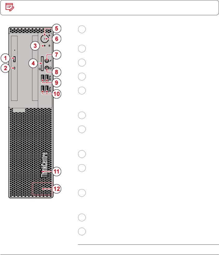
Front view
Note Your computer model might look slightly different from the illustration.
1 |
Optical drive eject/close button |
|
Used to eject the tray of the optical drive. After you insert a disc |
|
into the tray, press the eject/close button to close the tray. |
2 |
Optical drive status indicator |
|
This indicator is on when the optical drive is in use. |
3 |
Storage drive status indicator |
|
This indicator is on when the storage drive is in use. |
4 |
Card reader slot (optional) |
|
Used to read data from a supported memory card. |
5 |
Power button |
|
Used to turn on your computer. When you cannot shut down the |
|
computer from the operating system, press and hold the power |
|
button for four or more seconds to turn off the computer. |
6 |
Power indicator |
|
This indicator is on when the computer is on. |
7 |
Microphone connector |
|
Used to connect a microphone to your computer. You can use the |
|
microphone to record sounds or interact with the computer using |
|
speech-recognition software. |
8 |
Headphone connector |
|
Used to connect headphones to your computer. |
9 |
USB 3.1 connectors (2) |
|
Used to connect a USB-compatible device. For optimal data |
|
transfer, connect a USB 3.1 device to a USB 3.1 connector instead |
|
of a USB 3.0 or USB 2.0 connector. |
10 |
USB 3.0 connectors (2) |
|
Used to connect a USB-compatible device. For optimal data |
|
transfer, connect a USB 3.0 device to a USB 3.1 or USB 3.0 |
|
connector instead of a USB 2.0 connector. |
11 |
Illuminated red dot |
|
This indicator is on when the computer is on. |
12 |
Internal speaker (optional) |
|
Used to listen to the sounds from your computer without using a |
headset or headphones.
Overview |
3 |
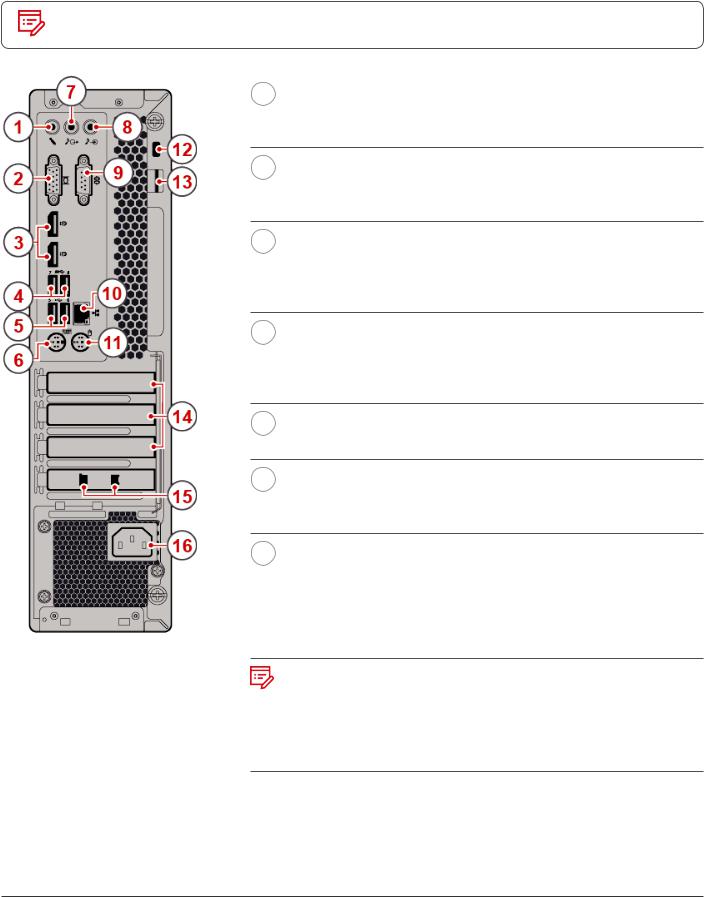
Rear view
Note |
Your computer model might look slightly different from the illustration. |
1 Microphone connector
Used to connect a microphone to your computer when you want to record sound or use speech recognition software.
2 VGA-out connector
Used to send video signals from the computer to another video device, such as a monitor.
3 DisplayPort®-out connectors (2)
Used to send audio and video signals from the computer to another audio or video device, such as a high-performance monitor.
4 USB 3.0 connectors (2)
Used to connect a USB-compatible device. For optimal data transfer, connect a USB 3.0 device to a USB 3.1 or USB 3.0 connector instead of a USB 2.0 connector.
5 USB 2.0 connectors (2)
Used to connect a device that requires a USB 2.0 connection.
6 PS/2 keyboard connector
Used to connect a keyboard that uses a Personal System/2 (PS/2) keyboard connector.
7 Audio line-out connector
Used to send audio signals from the computer to external devices, such as powered stereo speakers, headphones, or multimedia keyboards. To connect a stereo system or other external recording device, connect a cable between the audio line-in connector of the device and the audio line-out connector of the computer.
Note
If your computer has both an audio line-out connector and a headset or headphone connector, always use the headset connector or headphone connector for earphones, headphones, or a headset. The headphone connector does not support headset microphones.
Overview |
4 |

8 Audio line-in connector
Used to receive audio signals from an external audio device, such as a stereo system. To attach an external audio device, connect a cable between the audio line-out connector of the device and the audio line-in connector of the computer.
9 Serial connector
Used to connect an external modem, a serial printer, or other devices that use a serial connector.
10 Ethernet connector
Used to connect an Ethernet cable for network access.
11 PS/2 mouse connector
Used to connect a mouse, a trackball, or other pointing devices that use a PS/2 mouse connector.
12 |
Security-lock slot |
Used to secure a Kensington-style cable lock.
13 Padlock loop
Used to secure a padlock.
14 PCI-Express card area
To improve the operating performance of the computer, you can connect PCI-Express cards into this area. Depending on the computer model, the connectors in this area vary.
15 Cable lock slots (2) (optional)
Used to secure a cable lock.
16 Power cord connector
Used to connect the power cord to your computer for power supply.
Overview |
5 |

System board
Note |
See |
|
or |
|
for additional component descriptions. |
Front view |
Rear view |
1 |
4-pin power connector |
|
|
2 |
Microprocessor fan connector |
|
|
3 |
Internal speaker connector |
|
|
4 |
Storage drive status indicator |
|
|
5 |
Power button board connector |
|
|
6 |
SATA power connectors (2) |
|
|
7 |
10-pin power connector |
|
|
8 |
SATA 3.0 connectors (3) |
|
|
9 |
Auxiliary fan connector 1 |
|
|
10 |
Illuminated red dot connector |
|
|
11 |
Thermal sensor connector |
|
|
12 |
M.2 solid-state drive slot |
|
|
13 |
Front USB 2.0 connector (Card reader |
|
connector) |
|
|
14 |
Front USB 2.0 connector |
|
|
Overview |
6 |
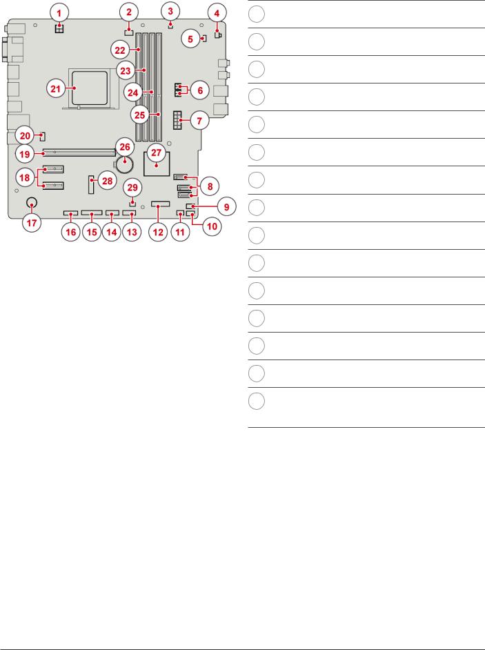
15Parallel connector
16Serial (COM2) connector
17Buzzer
18PCI Express x1 card slots (2)
19PCI Express x16 graphics card slot
20System fan connector
21Microprocessor socket
22Memory slot (DIMM1)
23Memory slot (DIMM2)
24Memory slot (DIMM3)
25Memory slot (DIMM4)
26Coin-cell battery
27PCH
28M.2 Wi-Fi card slot
29Cover presence switch connector (Intrusion switch connector)
Overview |
7 |
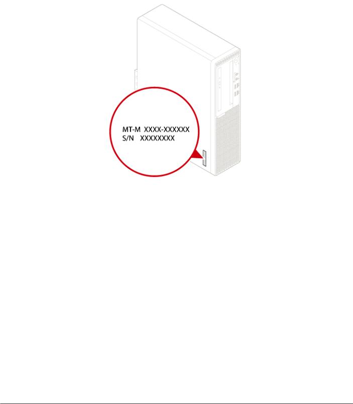
Machine type and model label
The machine type and model label identifies the computer. When you contact Lenovo for help, the machine type and model information helps support technicians to identify the computer and provide faster service.
The machine type and model label is attached on the side of the computer as shown.
Overview |
8 |

Specifications
Power supply
•• 180 watt automatic voltage-sensing power supply
•• 210 watt automatic voltage-sensing power supply
Storage drives |
Up to two 2.5-inch or 3.5-inch storage drives and one M.2 solid-state drive |
|
|
Video features |
The integrated graphics card supports the following: |
|
•• DisplayPort-out connector |
|
•• VGA-out connector |
Audio features
The integrated audio card supports the following:
•• Audio line-in connector
•• Audio line-out connector
•• Headphone connector
•• Internal speaker (optional)
•• Microphone connector
The optional discrete audio card provides an enhanced audio experience and extended capabilities.
Input/Output (I/O) features
•• Audio connectors (audio line-in, audio line-out, headphone, and microphone)
•• Card reader slot (optional)
•• Display connectors (DisplayPort-out and VGA-out)
•• Ethernet connector
•• PS/2 keyboard connector
•• PS/2 mouse connector
•• Serial connector
•• USB connector
Expansion |
•• Card reader (optional) |
|
•• Memory slot |
|
•• Optical drive |
|
•• PCI Express x1 card slot |
|
•• PCI Express x16 graphics card slot |
|
•• Storage drive bay |
|
|
Specifications |
9 |

Network features
•• Ethernet LAN
•• Wireless LAN (optional)
•• Bluetooth (optional)
Physical dimensions
•• Width: 92.5 mm (3.6 inches)
•• Height: 343.5 mm (13.5 inches)
•• Depth: 290.5 mm (11.4 inches)
Weight (without the package) •• Maximum configuration as shipped: 6.0 kg (13.2 lb)
Specifications |
10 |
Locking the computer
Locking the computer cover
Locking the computer cover helps prevent unauthorized access to the inside of your computer. Your computer features a padlock loop so that the computer cover cannot be removed when a padlock is installed.
Attaching a Kensington-style cable lock
You can use a Kensington-style cable lock to secure your computer to a desk, table, or other nonpermanent fixture. The cable lock connects to the security-lock slot at the rear of your computer. Depending on the type selected, the cable lock can be operated with a key or combination. The cable lock also locks the buttons used to open the computer cover. This is the same type of lock used with many notebook computers. You can order such a cable lock directly from Lenovo by searching for Kensington at: http://www.lenovo.com/support.
Attaching a cable lock
A cable lock can be used to secure devices, such as the keyboard and the mouse, by locking the device cables to the computer. The cable lock connects to the cable-lock slots on the rear of the computer.
To install a cable lock, do the following:
1
2
Insert the clip 1 into the cable-lock slot 4.
Guide the cables you want to lock into the grooves of the cable lock.
3 |
Press the clip 2 into the cable-lock slot 3 until it snaps into |
|
|
|
position. |
Locking the computer |
11 |

Replacing hardware
Before replacing hardware
 Attention
Do not open your computer or attempt any repairs before reading the Important Product Information Guide.
Read these notes before replacing hardware:
••Some of the hardware components explained in this manual are optional.
••Use computer components provided only by Lenovo.
••When installing or replacing an option, use the appropriate instructions explained in this manual along with the instructions that come with the option.
••In most areas of the world, Lenovo requires the return of defective CRUs. Information about this will come with the CRU or will come a few days after the CRU arrives.
Handling static-sensitive devices
Do not open the static-protective package containing the new component until the defective component has been removed and you are ready to install the new component. Static electricity, although harmless to you, can seriously damage computer components.
When you handle parts and other computer components, take these precautions to avoid static damage:
••Limit your movement. Movement can cause static electricity to build up around you.
••Always handle parts and other computer components carefully. Handle PCI/PCI-Express cards, memory modules, system boards, and microprocessors by the edges. Never touch any exposed circuitry.
••Prevent others from touching the parts and other computer components.
••Touch the static-protective package containing the part to a metal expansion-slot cover or other unpainted metal surface on the computer for at least two seconds. This reduces static electricity from the package and your body before you install or replace a new part.
••When possible, remove the new part from the static-protective package, and install it directly in the computer without setting the part down. When this is not possible, place the static-protective package that the part came in on a smooth, level surface and place the part on the package.
••Do not place the part on the computer cover or other metal surface.
Replacing hardware |
12 |

Knowing replaceable parts
Customer-Replaceable Units (CRUs)
CRUs are computer parts that a user can upgrade or replace. There are two types of CRUs: self-service and optional-service.
Self-service CRUs
Note
You can install self-service CRUs easily. These CRUs might be standalone, latched, or secured by up to two screws.
Examples of self-service CRUs include the keyboard, mouse, any USB device, and the power cord. Other self-service CRUs might include memory modules, adapter cards, hard disk drives, and optical drives.
Users are responsible for replacing all self-service CRUs.
Optional-service
CRUs
Handling optional-service CRUs requires some technical skills and simple tools (such as a screwdriver).
These CRUs are isolated parts within the computer. They are usually concealed by an access panel that is secured by more than two screws. You must remove the screws and panel to access the specific CRU.
Optional-service CRUs can be removed and installed by users or, during the warranty period, by a Lenovo service technician.
Field Replaceable Units (FRUs)
FRUs are computer parts that a trained technician can upgrade or replace.
For detailed FRU information, such as the FRU part numbers and supported computer models, go to: http://www.lenovo.com/serviceparts-lookup
Replacing hardware |
13 |

CRUs and FRUs locations
Refer to the following illustrations to check the locations of CRUs and FRUs within the computer.
Note |
Some of the following parts are optional on some models. |
Self-service CRU
1 |
Computer cover |
|
|
|
|
|
|
|
|
|
|
|
|
|
|
|
|||||||
p. 22 |
|||||||||||||||||||||||
|
|
|
|
|
|
|
|
|
|
|
|
|
|
|
|
|
|
|
|
|
|
|
|
6 |
Coin-cell battery |
|
|
|
|
|
|
|
|
|
|
|
|
||||||||||
p. 33 |
|||||||||||||||||||||||
|
|
|
|
|
|
|
|
|
|
|
|
|
|
|
|
|
|
|
|
|
|
|
|
8 |
Memory module |
|
|
|
|
|
|
|
|
|
|
|
|||||||||||
p. 29 |
|||||||||||||||||||||||
|
|
|
|
|
|
|
|
|
|
|
|
|
|
|
|
|
|
|
|
|
|
|
|
10 |
M.2 solid-state drive |
|
|
|
|
|
|
|
|||||||||||||||
p. 34 |
|||||||||||||||||||||||
|
|
|
|
|
|
|
|
|
|
|
|
|
|
|
|
|
|
|
|
|
|
|
|
11 |
M.2 solid-state drive bracket |
|
|
||||||||||||||||||||
p. 36 |
|||||||||||||||||||||||
|
|
|
|
|
|
|
|
|
|
|
|
|
|
|
|
|
|
|
|
|
|
|
|
12 |
Secondary storage drive |
||||||||||||||||||||||
|
bracket |
|
|
|
|
|
|
|
|
|
|
|
|
||||||||||
|
p. 26 |
||||||||||||||||||||||
|
|
|
|
|
|
|
|
|
|
|
|
|
|
|
|
|
|
|
|
|
|
|
|
13 |
Secondary storage drive (a 2.5- |
||||||||||||||||||||||
|
inch storage drive) |
|
|
|
|
||||||||||||||||||
|
p. 26 |
||||||||||||||||||||||
|
|
|
|
|
|
|
|
|
|
|
|
|
|
|
|
|
|
|
|
|
|
|
|
18 |
Optical drive bracket |
|
|
||||||||||||||||||||
p. 24 |
|||||||||||||||||||||||
|
|
|
|
|
|
|
|
|
|
|
|
|
|
|
|
|
|
|
|
|
|
|
|
19 |
Optical drive |
|
|
|
|
||||||||||||||||||
p. 24 |
|||||||||||||||||||||||
|
|
|
|
|
|
|
|
|
|
|
|
|
|
|
|
|
|
|
|
|
|
|
|
20 |
Front bezel |
|
|
|
|
||||||||||||||||||
p. 23 |
|||||||||||||||||||||||
|
|
|
|
|
|
|
|
|
|
|
|
|
|
|
|
|
|
|
|
|
|
|
|
21 |
Dust shield |
|
|
||||||||||||||||||||
p. 20 |
|||||||||||||||||||||||
|
|
|
|
|
|
|
|
|
|
|
|
|
|
|
|
|
|
|
|
|
|
|
|
22 |
Keyboard |
||||||||||||||||||||||
|
|
|
|
|
|
|
|
|
|
|
|
|
|
|
|
|
|
|
|
|
|
|
|
23 |
Mouse |
||||||||||||||||||||||
|
|
|
|
|
|
|
|
|
|
|
|
|
|
|
|
|
|
|
|
|
|
|
|
24 |
Power cord |
||||||||||||||||||||||
|
|
|
|
|
|
|
|
|
|
|
|
|
|
|
|
|
|
|
|
|
|
|
|
Replacing hardware |
14 |
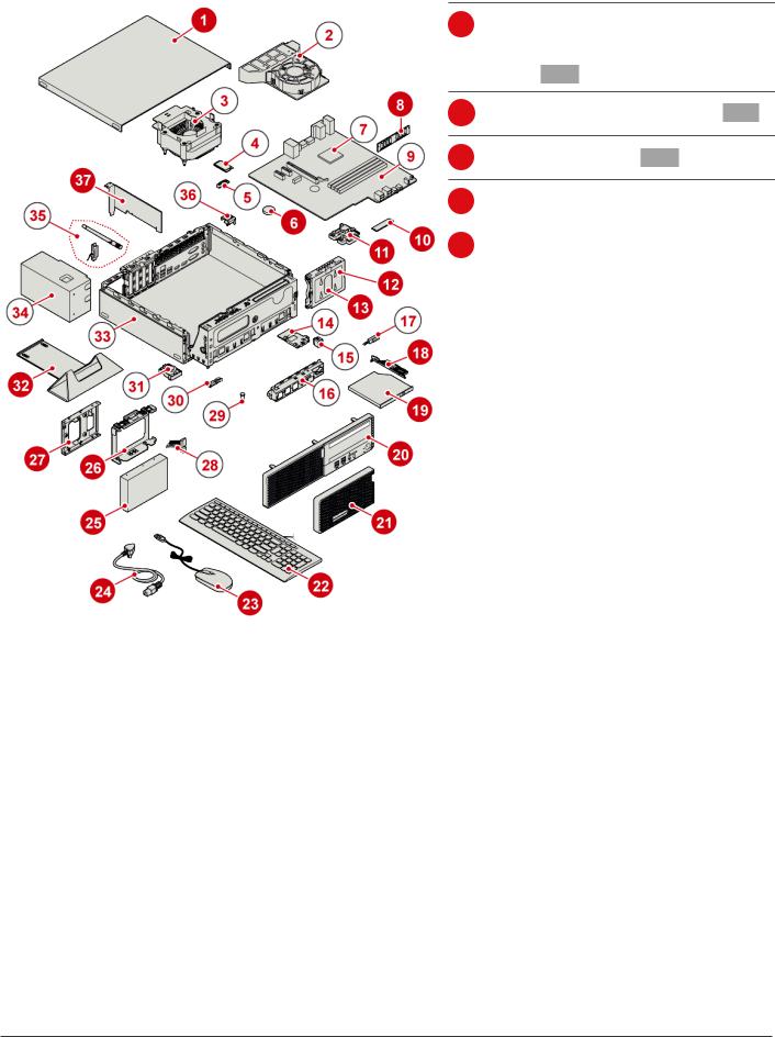
25Primary storage drive
(a 2.5-inch or 3.5-inch storage drive) p. 26
26Primary storage drive bracket p. 26
27Storage converter p. 26
32 |
Vertical stand |
|
|
|
|
p. 20 |
|||||
|
|
|
|
|
|
37 |
PCI Express card |
|
|
||
p. 30 |
|||||
|
|
|
|
|
|
Replacing hardware |
15 |
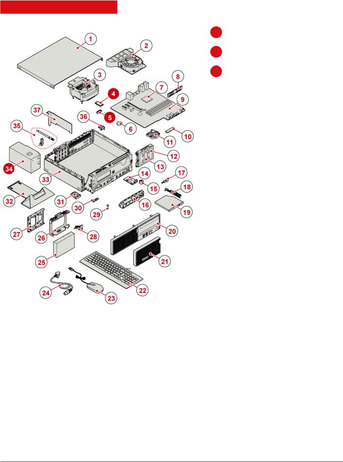
Optional-service CRU
4 |
Wi-Fi card |
|
|
|
|
|
|
p. 31 |
|||||||
|
|
|
|
|
|
|
|
5 |
Wi-Fi card shield |
|
|
|
|
||
p. 31 |
|||||||
|
|
|
|
|
|
|
|
34 |
Power supply assembly |
|
|
||||
p. 37 |
|||||||
|
|
|
|
|
|
|
|
Replacing hardware |
16 |
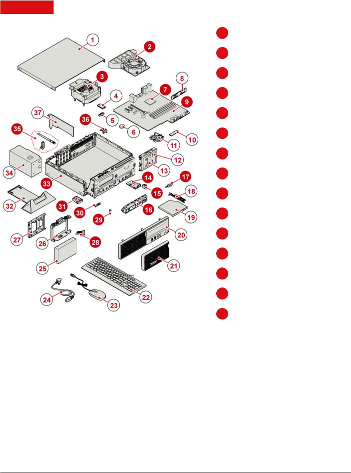
FRU
2 |
Heat sink fan duct |
|
|
|
|
|
|
|
|
|
|
|
|
|
|
|
|
||||||||
p. 50 |
|||||||||||||||||||||||||
|
|
|
|
|
|
|
|
|
|
|
|
|
|
|
|
|
|
|
|
|
|
|
|
|
|
3 |
Heat sink and fan assembly |
|
|
||||||||||||||||||||||
p. 50 |
|||||||||||||||||||||||||
|
|
|
|
|
|
|
|
|
|
|
|
|
|
|
|
|
|
|
|
|
|
|
|
|
|
7 |
Microprocessor |
|
|
|
|
|
|
|
|
|
|
|
|
|
|
|
|
|
|||||||
p. 51 |
|||||||||||||||||||||||||
|
|
|
|
|
|
|
|
|
|
|
|
|
|
|
|
|
|
|
|
|
|
|
|
|
|
9 |
System board |
|
|
|
|
|
|
|
|
|
|
|
|
|
|
|
|
|
|||||||
p. 54 |
|||||||||||||||||||||||||
|
|
|
|
|
|
|
|
|
|
|
|
|
|
|
|
|
|
|
|
|
|
|
|
|
|
14 |
Card reader |
|
|
|
|
|
|
|
|
|
|
|
|
|
|
|
|
||||||||
p. 48 |
|||||||||||||||||||||||||
|
|
|
|
|
|
|
|
|
|
|
|
|
|
|
|
|
|
|
|
|
|
|
|
|
|
15 |
Power button board |
|
|
|
|
|
|
|
|
||||||||||||||||
p. 48 |
|||||||||||||||||||||||||
|
|
|
|
|
|
|
|
|
|
|
|
|
|
|
|
|
|
|
|
|
|
|
|
|
|
16 |
Front I/O bracket |
|
|
|
|
|
|
|
|
|
|
||||||||||||||
p. 48 |
|||||||||||||||||||||||||
|
|
|
|
|
|
|
|
|
|
|
|
|
|
|
|
|
|
|
|
|
|
|
|
|
|
17 |
Optical drive cable |
||||||||||||||||||||||||
|
|
|
|
|
|
|
|
|
|
|
|
|
|
|
|
|
|
|
|
|
|
|
|
|
|
28 |
Storage drive cable |
||||||||||||||||||||||||
|
|
|
|
|
|
|
|
|
|
|
|
|
|
|
|
|
|
|
|
|
|
|
|
|
|
29 |
Illuminated red dot |
|
|
|
|
|
|
||||||||||||||||||
p. 45 |
|||||||||||||||||||||||||
|
|
|
|
|
|
|
|
|
|
|
|
|
|
|
|
|
|
|
|
|
|
|
|
|
|
30 |
Thermal sensor |
|
|
|
|
|
|
|
|
||||||||||||||||
p. 46 |
|||||||||||||||||||||||||
|
|
|
|
|
|
|
|
|
|
|
|
|
|
|
|
|
|
|
|
|
|
|
|
|
|
31 |
Internal speaker |
|
|
|
|
|
|
||||||||||||||||||
p. 43 |
|||||||||||||||||||||||||
|
|
|
|
|
|
|
|
|
|
|
|
|
|
|
|
|
|
|
|
|
|
|
|
|
|
33 |
Chassis |
||||||||||||||||||||||||
|
|
|
|
|
|
|
|
|
|
|
|
|
|
|
|
|
|
|
|
|
|
|
|
|
|
35 |
Wi-Fi antennas (2) |
|
|
|
|||||||||||||||||||||
p. 41 |
|||||||||||||||||||||||||
|
|
|
|
|
|
|
|
|
|
|
|
|
|
|
|
|
|
|
|
|
|
|
|
|
|
36 |
Cover presence switch |
||||||||||||||||||||||||
|
(Intrusion switch) |
|
|
||||||||||||||||||||||
|
p. 53 |
||||||||||||||||||||||||
|
|
|
|
|
|
|
|
|
|
|
|
|
|
|
|
|
|
|
|
|
|
|
|
|
|
Replacing hardware |
17 |
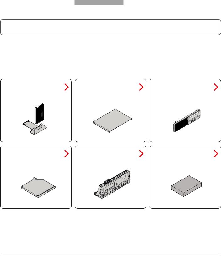
Replacing CRUs
Before replacing CRUs
To check the locations of CRUs, see CRUs and FRUs locations.
 Attention
Do not open your computer or attempt any repairs before reading the Important Product Information Guide.
Before replacing a CRU, click the illustration of the part to check the brief procedures.
External options |
Computer cover |
Front bezel |
Optical drive |
Drive bay assembly |
Storage drive |
Replacing CRUs |
18 |
 Loading...