

Page 1

OPTISWIRL 4200
OPTISWIRL 4200
OPTISWIRL 4200OPTISWIRL 4200
Vortex flowmeter
Electronic revision: ER 1.0.5_
Quick Start
Quick Start
Quick StartQuick Start
© KROHNE 03/2016 - 4003931402 - QS OPTISWIRL 4200 R02 en
Page 2

CONTENTS
OPTISWIRL 4200
1 Safety instructions 3
2 Installation 4
2.1 Intended use ..................................................................................................................... 4
2.2 Scope of delivery............................................................................................................... 6
2.3 Storage ............................................................................................................................. 6
2.4 Transport .......................................................................................................................... 7
2.5 Installation conditions ...................................................................................................... 8
2.5.1 Prohibited installation when measuring liquids .................................................................... 9
2.5.2 Prohibited installation when measuring steam and gases.................................................. 10
2.5.3 Pipelines with control valve .................................................................................................. 10
2.5.4 Preferred mounting position ................................................................................................ 11
2.6 Minimum inlet sections.................................................................................................. 12
2.7 Minimum outlet sections................................................................................................ 13
2.8 Flow straightener ........................................................................................................... 13
2.9 Installation...................................................................................................................... 14
2.9.1 General installation notes..................................................................................................... 14
2.9.2 Installing devices in sandwich design .................................................................................. 15
2.9.3 Installing devices in flange design ....................................................................................... 16
2.9.4 Mounting the field housing, remote version ........................................................................ 17
2.10 Heat insulation.............................................................................................................. 18
2.11 Turning the connection housing................................................................................... 19
2.12 Turning the display .......................................................................................................20
3 Electrical connections 21
3.1 Safety instructions.......................................................................................................... 21
3.2 Connecting the signal converter .................................................................................... 22
3.3 Electrical connections .................................................................................................... 23
3.3.1 Power supply......................................................................................................................... 23
3.3.2 Current output ...................................................................................................................... 23
3.3.3 Current input......................................................................................................................... 24
3.3.4 Binary output......................................................................................................................... 24
3.3.5 Limit switch output ............................................................................................................... 25
3.3.6 Pulse output / Frequency output ..........................................................................................27
3.3.7 Status output......................................................................................................................... 28
3.4 Connection of remote version ........................................................................................ 28
3.5 Grounding connections................................................................................................... 30
3.6 Ingress protection .......................................................................................................... 31
2
www.krohne.com 03/2016 - 4003931402 - QS OPTISWIRL 4200 R02 en
Page 3

OPTISWIRL 4200
Warnings and symbols used
DANGER!
This information refers to the immediate danger when working with electricity.
DANGER!
These warnings must be observed without fail. Even partial disregard of this warning can lead to
serious health problems and even death. There is also the risk of seriously damaging the device
or parts of the operator's plant.
WARNING!
Disregarding this safety warning, even if only in part, poses the risk of serious health problems.
There is also the risk of damaging the device or parts of the operator's plant.
CAUTION!
Disregarding these instructions can result in damage to the device or to parts of the operator's
plant.
INFORMATION!
These instructions contain important information for the handling of the device.
SAFETY INSTRUCTIONS
1
HANDLING
• This symbol designates all instructions for actions to be carried out by the operator in the
specified sequence.
i RESULT
RESULT
RESULTRESULT
This symbol refers to all important consequences of the previous actions.
Safety instructions for the operator
CAUTION!
Installation, assembly, start-up and maintenance may only be performed by appropriately
trained personnel. The regional occupational health and safety directives must always be
observed.
LEGAL NOTICE!
The responsibility as to the suitability and intended use of this device rests solely with the user.
The supplier assumes no responsibility in the event of improper use by the customer. Improper
installation and operation may lead to loss of warranty. In addition, the "Terms and Conditions of
Sale" apply which form the basis of the purchase contract.
INFORMATION!
•
Further information can be found on the supplied CD-ROM in the manual, on the data sheet,
in special manuals, certificates and on the manufacturer's website.
•
If you need to return the device to the manufacturer or supplier, please fill out the form
contained on the CD-ROM and send it with the device. Unfortunately, the manufacturer
cannot repair or inspect the device without the completed form.
www.krohne.com03/2016 - 4003931402 - QS OPTISWIRL 4200 R02 en
3
Page 4

2
INSTALLATION
2.1 Intended use
CAUTION!
Responsibility for the use of the measuring devices with regard to suitability, intended use and
corrosion resistance of the used materials against the measured fluid lies solely with the
operator.
INFORMATION!
This device is a Group 1, Class A device as specified within CISPR11:2009. It is intended for use in
industrial environment. There may be potential difficulties in ensuring electromagnetic
compatibility in other environments, due to conducted as well as radiated disturbances.
INFORMATION!
The manufacturer is not liable for any damage resulting from improper use or use for other than
the intended purpose.
The vortex flowmeters are used for flow measurement of gases, vapours and liquids.
The devices are particularly suitable for the measurement of:
• Clean liquids with low viscosity (< 10 cP)
• Hydrocarbons with low viscosity (< 10 cP)
• Water
• Chemicals with low corrosiveness
• Saturated steam
• Superheated steam, including CIP and SIP applications in the food industry
OPTISWIRL 4200
®
• The flow sensors are made from stainless steel 316 L (1.4404) or Hastelloy
• In your project planning, please observe the data given in the corrosion tables.
• The pressure-bearing parts have been designed and rated for stationary operation taking into
account the maximum pressure and temperature.
• Observe the data indicated on the nameplate for PS, TS and PT (PED 97/23/EC).
• External forces and moments, caused e.g. by pipe stresses, have not been taken into account.
Primarily, volumetric flow and temperature are measured, with pressure measurement as an
option. From these parameters the measuring device calculates the mass flow or standard
volumetric flow using pre-programmed density data and then exports the measured values via
various communication interfaces.
C22.
4
www.krohne.com 03/2016 - 4003931402 - QS OPTISWIRL 4200 R02 en
Page 5

OPTISWIRL 4200
The devices are rated for the following flow velocities:
INSTALLATION
2
Liquids:
DN15...DN300
Gases and
steam:
DN15 V
DN15C V
DN25 V
DN25C V
V
: 0.25 m/s 0.8 ft/s 1
min
V
: 10 m/s 32 ft/s 2
max
: 3 m/s 10 ft/s 1
min
V
: 45 m/s 147 ft/s 2
max
: 3 m/s 10 ft/s 1
min
V
: 55 m/s 180 ft/s 2
max
: 2 m/s 6.6 ft/s 1
min
V
: 70 m/s 229 ft/s 2
max
: 2 m/s 6.6 ft/s 1
min
V
: 80 m/s 262 ft/s 2
max
DN40...
DN300
V
: 2 m/s 6.6 ft/s 1
min
V
: 80 m/s 262 ft/s 2
max
1 Use the larger value, according to the amount.
2 Use the smaller value, according to the amount.
INFORMATION!
DN15C and DN25C have a robust flow sensor (signal pick-up) for harsh measuring conditions
and higher maximum velocity compared to the standard version.
www.krohne.com03/2016 - 4003931402 - QS OPTISWIRL 4200 R02 en
5
Page 6

2
INSTALLATION
2.2 Scope of delivery
INFORMATION!
Inspect the packaging carefully for damages or signs of rough handling. Report damage to the
carrier and to the local office of the manufacturer.
INFORMATION!
Do a check of the packing list to make sure that you have all the elements given in the order.
INFORMATION!
Look at the device nameplate to ensure that the device is delivered according to your order.
Check for the correct supply voltage printed on the nameplate.
OPTISWIRL 4200
Figure 2-1: Scope of delivery
1 Measuring device in ordered version
2 Product documentation
3 Certificates, calibration report and parameter data sheet
4 CD with complete documentation
5 Bar magnet
6 Centering rings (only for sandwich devices)
7 Handle to pull off the display
8 Key for opening the front and rear cover
2.3 Storage
• Store the device in a dry, dust-free location.
• Avoid extended direct exposure to the sun.
• Store the device in the original packaging.
• The permissible storage temperature for standard devices is -40...+85°C / -40...+185°F.
6
www.krohne.com 03/2016 - 4003931402 - QS OPTISWIRL 4200 R02 en
Page 7
OPTISWIRL 4200
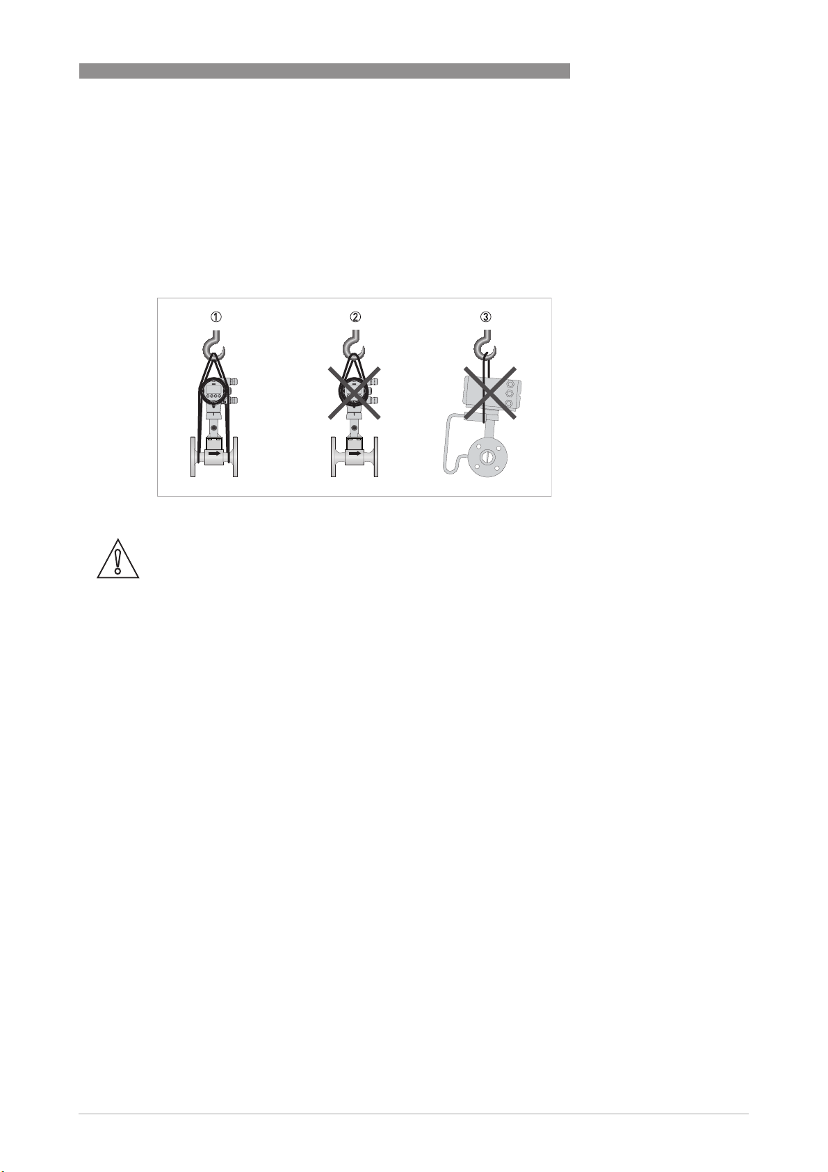
2.4 Transport
• Use lifting straps wrapped around both process connections for transport.
• Do not lift measuring devices by the signal converter housing for transport.
• Never lift the measuring device by the pressure sensor.
• Do not use lifting chains as they may damage the housing.
INSTALLATION
2
Figure 2-2: Transport instructions
CAUTION!
Non-secured devices can pose risk of injury. The centre of mass of the device is often higher
than the point at which the lifting straps are attached.
Prevent the measuring device from sliding or rotating accidentally.
www.krohne.com03/2016 - 4003931402 - QS OPTISWIRL 4200 R02 en
7
Page 8

2
INSTALLATION
2.5 Installation conditions
INFORMATION!
For accurate volumetric flow measurement the measuring device needs a completely filled pipe
and a fully developed flow profile.
CAUTION!
Any vibration will distort the measuring result. That is why any vibrations in the pipeline must be
prevented through suitable measures.
CAUTION!
Procedures to carry out before installing the device:
•
Nominal diameter of connection pipe flange = nominal flange diameter of pipe!
•
Use flanges with smooth holes, e.g. welding neck flanges.
•
Align carefully the holes of the connecting flange and the flowmeter flange.
•
Check the compatibility of the gasket material with the process product.
•
Make sure that the gaskets are arranged concentrically. The flange gaskets must not project
into the pipe cross-section.
•
The flanges have to be concentric.
•
There must not be any pipe bends, valves, flaps or other internals in the immediate inlet run.
•
Devices in sandwich version may only be installed using centering rings.
•
Never install the device directly behind piston compressors or rotary piston meters.
•
Do not lay signal cables directly next to cables for the power supply.
OPTISWIRL 4200
INFORMATION!
If there is a risk of water hammers in steam networks, appropriate condensate separators must
be installed. Suitable measures must be taken to avoid water cavitation if it is a possible risk.
Sunshades
Figure 2-3: Installation recommendations
1 Horizontal mounting
2 Vertical mounting
The meter MUST be protected from strong sunlight.
A sunshade is available from the manufacturer as an option.
8
www.krohne.com 03/2016 - 4003931402 - QS OPTISWIRL 4200 R02 en
Page 9

OPTISWIRL 4200
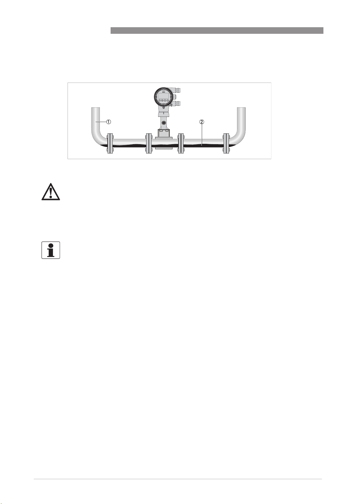
2.5.1 Prohibited installation when measuring liquids
Figure 2-4: Upper pipe bend
CAUTION!
Prohibited: Installing the device in an upper pipe bend 1, because there is a risk of gas bubbles
2 forming. Gas bubbles can lead to pressure surges and inaccurate measurement.
INSTALLATION
2
Figure 2-5: Downstream pipe and outlet
CAUTION!
Installing the device in a downstream pipe 3 or upstream pipe of an outlet 4. There is the risk of
partially filled pipes leading to inaccurate measurements.
www.krohne.com03/2016 - 4003931402 - QS OPTISWIRL 4200 R02 en
9
Page 10
2
INSTALLATION
2.5.2 Prohibited installation when measuring steam and gases
1 Lower pipe bends
2 Condensate
DANGER!
Prohibited: Installing the device in a lower pipe bend 1, because there is a risk of condensate
forming 2.
Condensate can lead to cavitation and inaccurate measurement. Under certain circumstances
the device can be destroyed and the measured product can leak.
OPTISWIRL 4200
2.5.3 Pipelines with control valve
INFORMATION!
To ensure smooth and correct measurement, the manufacturer recommends not installing the
measuring device downstream from a control valve. This would run the risk of vortex formation,
which would distort the measuring result.
Figure 2-6: Pipeline with control valve
1 Recommended: installing the device before the control valve at a distance of ≥ 5 DN
2 Not recommended: Installing the flowmeter directly downstream of control valves, due to vortex formation.
10
www.krohne.com 03/2016 - 4003931402 - QS OPTISWIRL 4200 R02 en
Page 11

OPTISWIRL 4200
2.5.4 Preferred mounting position
Preferred mounting position
INSTALLATION
2
Figure 2-7: Mountig position
1 Above a horizontal pipe
2 Underneath a horizontal pipe (not permitted with lines at risk of condensate forming)
3 On a vertical pipe
4 Horizontal pipeline with signal converter-orientation 90° to the side
INFORMATION!
Depending on the installation position, you may have to rotate the display and/or the connection
housing.
www.krohne.com03/2016 - 4003931402 - QS OPTISWIRL 4200 R02 en
11
Page 12

2
INSTALLATION
2.6 Minimum inlet sections
OPTISWIRL 4200
12
Figure 2-8: Inlet sections
1 General inlet section without disturbing flow ≥ 15 DN
2 Behind a control valve ≥ 50 DN
3 After a pipe diameter reduction ≥ 20 DN
4 After a single bend 90° ≥ 20 DN
5 After a double bend 2x90° ≥ 30 DN
6 After a double three-dimensional bend 2x90° ≥ 40 DN
7 Outlet section: >5 DN
INFORMATION!
The nominal diameter of the flange is significant for the determination of the minimum inlet and
outlet sections for the nominal diameter reduced versions of vortex flowmeter versions F1R and
F2R.
www.krohne.com 03/2016 - 4003931402 - QS OPTISWIRL 4200 R02 en
Page 13

OPTISWIRL 4200
2.7 Minimum outlet sections
INSTALLATION
2
Figure 2-9: Minimum outlet sections
1 Upstream of pipe expanders, pipe bends, control valves, etc. ≥ 5 DN
2 Upstream of measuring points ≥ 5 DN
INFORMATION!
The interior of the pipe at the metering points must be free of burrs and other flow impediments.
The measuring device has an internal temperature sensor. The distance from external
temperature measuring points must be ≥ 5 DN. Use flow sensors that are as short as possible to
avoid disturbances of the flow profile.
2.8 Flow straightener
If, due to the type of installation, the required inlet sections are not available, the manufacturer
recommends using flow straighteners. Flow straighteners are installed between two flanges
upstream of the device and shorten the required inlet section.
Figure 2-10: Flow straightener
1 Straight inlet section upstream of straightener ≥ 2 DN
2 Flow straightener
3 Straight pipe run between flow straightener and device ≥ 8 DN
4 Minimum straight outlet section ≥ 5 DN
www.krohne.com03/2016 - 4003931402 - QS OPTISWIRL 4200 R02 en
13
Page 14

2
INSTALLATION
2.9 Installation
2.9.1 General installation notes
CAUTION!
Installation, assembly, start-up and maintenance may only be performed by appropriately
trained personnel. The regional occupational health and safety directives must always be
observed.
The following procedures have to be carried out before installing the device:
• Ensure that the gaskets have the same diameter as the pipelines.
• Note the correct flow direction for the device. This is indicated by an arrow on the neck of the
flow sensor.
• On measuring points with varying thermal loads, the devices have to be mounted with stress
bolts (DIN 2510).
• Stress bolts or bolts and nuts are not included in the scope of delivery.
• Ensure that the measuring flange is concentrically fitted.
• Note the exact installation length of the measuring device when preparing the measuring
point.
OPTISWIRL 4200
Figure 2-11: Preparing the metering point
1 Installation length of measuring device + thickness of gaskets.
CAUTION!
The internal diameter of the pipelines, the flow sensor and the gaskets must match. The gaskets
may not protrude into the flow.
Figure 2-12: Inner diameter
1 Inner diameter of connection pipe
2 Inner diameter of flange and gasket
3 Inner diameter of flow sensor
14
www.krohne.com 03/2016 - 4003931402 - QS OPTISWIRL 4200 R02 en
Page 15

OPTISWIRL 4200
2.9.2 Installing devices in sandwich design
INSTALLATION
2
Figure 2-13: Installation using centering ring
1 Flow sensor
2 Centering ring
3 Bolts with fixing nuts
4 Drill hole
5 Sealing
• Push the first bolt 3 through the hole 4 of both flanges.
• Screw on the nuts and washers to both ends of the bolt 3 but do not tighten them.
• Install the second bolt through the holes 4.
• Place the flow sensor 1 between the two flanges.
• Insert the gaskets 5 between flow sensor 1 and flanges and align them.
• Check that the flange is concentric.
• Install the remaining bolts, washers and nuts. Do not yet tighten the nuts.
• Turn the centring ring 2 in a counter-clockwise direction and align the device.
• Check that the gaskets 5 are concentric; they must not protrude into the pipe cross-section.
• Now tighten all nuts bit by bit alternately across the diagonal.
www.krohne.com03/2016 - 4003931402 - QS OPTISWIRL 4200 R02 en
15
Page 16

2
INSTALLATION
2.9.3 Installing devices in flange design
OPTISWIRL 4200
Figure 2-14: Installing devices in flange design
1 Sealing
2 Bolts with fastening nuts
• Use bolts and fastening nuts 2 to attach the measuring device to one side of the flange.
• While doing so, insert the gaskets 1 between flow sensor and flange and align them.
• Check that the gasket is concentric and that it is not protruding into the pipe cross-section.
• Install the gasket, bolts and fastening nuts on the other side of the flange.
• Align the measuring device and the gaskets so they are concentric.
• Now tighten all nuts bit by bit alternately across the diagonal.
16
www.krohne.com 03/2016 - 4003931402 - QS OPTISWIRL 4200 R02 en
Page 17

OPTISWIRL 4200
2.9.4 Mounting the field housing, remote version
INFORMATION!
Assembly materials and tools are not part of the delivery. Use the assembly materials and tools
in compliance with the applicable occupational health and safety directives.
Pipe mounting
Figure 2-15: Pipe mounting of the field housing
INSTALLATION
2
1 Fix the signal converter to the pipe.
2 Fasten the signal converter using standard U-bolts and washers.
3 Tighten the nuts.
Wall mounting
Figure 2-16: Wall mounting of the field housing
1 Prepare the holes with the aid of the mounting plate.
2 Use the mounting material and tools in compliance with the applicable occupational health
and safety directives.
3 Fasten the housing securely to the wall.
INFORMATION!
Signal converters with a wall mounting rack have to be mounted with screws (Ø8 mm / 0.3") or
with U-brackets (Ø8 mm / 0.3") in case of pole installation. In case of mounting directly to the
wall, a mounting system with a minimum load force of 0.1 kN (for example FISCHER type UX10)
suitable for the background has to be applied.
www.krohne.com03/2016 - 4003931402 - QS OPTISWIRL 4200 R02 en
17
Page 18

2
INSTALLATION
2.10 Heat insulation
CAUTION!
For applications with medium temperatures above +160
in accordance to the insulation guideline is suggested. Avoid higher electronic temperatures
°
than +80
The area above the signal converter support must not be heat-insulated.
The heat insulation 3 may only extend to the maximum height 1 shown below.
C / +176°F.
OPTISWIRL 4200
°
C / +320°F an insulation of the pipeline
Figure 2-17: Installation heat insulation
1 Max. height of the insulation up to the marking on the neck of the flow sensor
2 Max. thickness of the insulation up to the bend of the pressure pipe
3 Insulation
CAUTION!
The heat insulation 3 may only extend as far as the bend of the pressure sensing line 2.
18
www.krohne.com 03/2016 - 4003931402 - QS OPTISWIRL 4200 R02 en
Page 19

OPTISWIRL 4200
2.11 Turning the connection housing
DANGER!
All work on the device electronics may only be carried out by appropriately trained personnel.
The regional occupational health and safety directives must always be observed.
INSTALLATION
2
Figure 2-18: Turning the connection housing
1 M4 Allen screw on connection housing
• Loosen the M4 Allen screw 1 on the side of the connection housing.
• Rotate the connection housing to the desired position (0...<360°).
• Tighten the M4 Allen screw 1 again.
www.krohne.com03/2016 - 4003931402 - QS OPTISWIRL 4200 R02 en
19
Page 20

2
INSTALLATION
2.12 Turning the display
DANGER!
All work on the device electronics may only be carried out by appropriately trained personnel.
The regional occupational health and safety directives must always be observed.
INFORMATION!
If the measuring device is installed in a vertical pipe, you will have to turn the display by 90
installed below a pipe, turn 180
INFORMATION!
The display can be turned in increments of 90
OPTISWIRL 4200
°
; if
°
.
°
to four positions.
Figure 2-19: Turning the display
Turn the display as follows:
• Disconnect the power supply from the measuring device.
• Unscrew the housing cover with the key 1.
• Please use the handle to pull out the display module.
• First put the handle on side "a" and then on side "b" of the display, and then pull out the
display 2 carefully. Turn it into the favoured position 3.
• Disconnect the display from the handle first on side "a" and then on side "b".
• Press the display onto the spacer pins 4, until it clicks.
• Turn the cover with gasket 5 back onto the housing and tighten it by hand.
20
www.krohne.com 03/2016 - 4003931402 - QS OPTISWIRL 4200 R02 en
Page 21

OPTISWIRL 4200
3.1 Safety instructions
DANGER!
All work on the electrical connections may only be carried out with the power disconnected. Take
note of the voltage data on the nameplate.
DANGER!
Observe the national regulations for electrical installations!
DANGER!
For devices used in hazardous areas, additional safety notes apply; please refer to the Ex
documentation.
WARNING!
Observe without fail the local occupational health and safety regulations. Any work done on the
electrical components of the measuring device may only be carried out by properly trained
specialists.
ELECTRICAL CONNECTIONS
3
INFORMATION!
Check the device nameplate to ensure that the device is delivered according to your order. Check
for the correct supply voltage printed on the nameplate.
www.krohne.com03/2016 - 4003931402 - QS OPTISWIRL 4200 R02 en
21
Page 22

3
ELECTRICAL CONNECTIONS
3.2 Connecting the signal converter
DANGER!
All work on the electrical connections may only be carried out with the power disconnected. Take
note of the voltage data on the nameplate!
INFORMATION!
When using the binary output M1...M4 as pulse output and frequencies above 100 Hz, shielded
cables are to be used in order to reduce effects from electrical interferences (EMC).
OPTISWIRL 4200
Figure 3-1: Connecting the signal converter
1 Open the housing cover of the electrical terminal compartment using the key
2 Signal converter supply and 4...20 mA loop
3 4...20 mA current input, - external transmitter, optional
4 Terminal M1 binary (high current)
5 Terminal M3 binary (NAMUR)
6 Terminal M2/4 binary, common minus connection
7 Ground terminal in housing
8 Ground terminal on connection piece between flow sensor and signal converter
INFORMATION!
Both grounding terminals 7 and 8 are equally effective from a technical point of view.
Steps for connecting the signal converter:
• Unscrew the housing cover 1 of the electrical terminal compartment.
• Feed the connection cable through the cable entry in the housing.
• Connect the cable according to the terminal diagrams below.
• Connect the grounding to the terminal 7. Alternatively use the ground terminal 8 on the
connection piece between the flow sensor and the signal converter.
• Tighten the cable glands.
• Turn the housing cover and gasket back onto the housing and tighten it by hand.
INFORMATION!
Ensure that the housing gasket is properly fitted, clean and undamaged.
22
www.krohne.com 03/2016 - 4003931402 - QS OPTISWIRL 4200 R02 en
Page 23

OPTISWIRL 4200
3.3 Electrical connections
The signal converter is a 2-wire device with 4...20 mA as output signal. All other inputs and
outputs are passive and always require an additional power supply.
3.3.1 Power supply
INFORMATION!
The supply voltage has to be between 12 VDC and 36 VDC (12...30 VDC for Ex). This is based on
the total resistance of the measuring loop. To calculate this, the resistance of each component in
the measuring loop (not including the device) must be added up.
The required supply voltage can be calculated using the formula below:
= RL * 22 mA + 12 V
U
ext.
with
U
= the minimum supply voltage
ext.
= the total measuring loop resistance
R
L
INFORMATION!
The power supply has to be able to supply a minimum of 22 mA.
ELECTRICAL CONNECTIONS
3
3.3.2 Current output
Figure 3-2: Electrical connection current output
1 Power supply for current output
2 Optional display unit (R
3 Load for HART
Connect current loop 4..20 mA to terminals C1+ and C2-.
When connection cables are long, a shielded or twisted cable may be necessary. The cable shield
may only be grounded at one place (e.g. on the power supply unit).
®
≥ 250 Ω
)
L
www.krohne.com03/2016 - 4003931402 - QS OPTISWIRL 4200 R02 en
23
Page 24

3
ELECTRICAL CONNECTIONS
3.3.3 Current input
An external transmitter, e.g. temperature or pressure transmitter, can be connected to
terminals I1+ and I2-. The 4...20 mA current signal is converted to the corresponding
temperature or pressure value in the signal converter.
OPTISWIRL 4200
Figure 3-3: Electrical connection current input
1 Power supply for the signal converter
2 Current input of an external temperature or pressure transmitter
The current input can be configured in menu C1.5. Depending on the configuration of the current
input, the sources for temperature and/or pressure value have to be adjusted in menu C1.6 or
C1.7.
3.3.4 Binary output
Unless otherwise ordered, the binary output is inactive by default and must thus be activated and
configured as limit switch output, pulse output, frequency output or status output in menu C2.2
prior to first use. The binary output is electrically separated from the current output and must be
supplied with power separately.
24
www.krohne.com 03/2016 - 4003931402 - QS OPTISWIRL 4200 R02 en
Page 25

OPTISWIRL 4200
3.3.5 Limit switch output
Figure 3-4: Connection binary output
1 Power supply U
2 Isolated switching amplifier
ext.
ELECTRICAL CONNECTIONS
3
INFORMATION!
Binary output Mx can only be operated if the loop supply 4...20 mA is applied to the terminals C1+
and C2-. The binary output is inactive by default and must thus be activated in menu C2.2 prior to
first use.
Connection binary output
Connection binary output
Connection binary outputConnection binary output
In accordance with the desired signal transmission, select one of the following connection types
for binary output M:
• M2/4 and M3 - NAMUR (DC interface in accordance with EN 60947-5-6)
• M2/4 and M1 - Transistor output (passive, open collector)
Terminal connection
Terminal M1 M3 M2/4
Connection NAMUR + (open collector,
Connection transistor output + (open collector,
I
max
< 100 mA)
Ri~1kΩ)
Common
Common
www.krohne.com03/2016 - 4003931402 - QS OPTISWIRL 4200 R02 en
25
Page 26

3
ELECTRICAL CONNECTIONS
Value range for NAMUR
Switching value reached < 1 mA > 3 mA
Switching value not reached > 3 mA < 1 mA
1 C2.2.6 Invert Signal On
2 C2.2.6 Invert Signal Off
Value range applies only when connected to a switching amplifier with the following reference
values:
- Open-circuit voltage U
- Internal resistance R
=8.2VDC
0
=1kΩ
i
Value range for transistor output
OPTISWIRL 4200
NC contact 1 NO contact 2
via load R
U
L
L
0...2 V 0...2 mA 16...30 V 20...100 mA
I
L
U
H
I
H
To ensure the value ranges, a load RL between 250 Ω and 1 kΩ is recommended for the passive
transistor output with a nominal voltage of 24 VDC. If other loads are used, caution is advised as
the range of values of the signal voltages then no longer corresponds to the range of values for
the inputs of process control systems and controls (DIN IEC 946).
CAUTION!
The upper limit of the signal current must not be exceeded as this may damage the transistor
output.
For selection of measurement variable and adjustable data of the limit switch refer to chapter
"Menu description C - Setup", menu "C2.2.5 Limit Switch" and appropriate submenus.
26
www.krohne.com 03/2016 - 4003931402 - QS OPTISWIRL 4200 R02 en
Page 27

OPTISWIRL 4200
3.3.6 Pulse output / Frequency output
The maximum frequency of both pulse output and frequency output is 1000 Hz.
Figure 3-5: Electrical connection pulse output
1 Signal converter power supply
2 Pulse output power supply
3 Pulse counter or frequency meter
ELECTRICAL CONNECTIONS
3
The connection is made between terminal M2/4 Common (-) and M1 for Hi Current (+) or M3
NAMUR (+). Only one of the two connections M1 or M3 can be selected in menu C2.2. The output
is selected as pulse or frequency output in menu C2.2. The output is a passive "open collector"
output which is electrically separated from the current interface and the flow sensor. It requires
its own power supply 2. The total resistance must be adapted so that the total current I
tot
does
not exceed 120 mA.
Figure 3-6: Pulse output signal definition
1 T
max
2 Closed
3 Open
4 Pulse width ≥ 0.5 ms
For selection of measurement variable and adjustable data of the pulse or frequency output
refer to chapter "Menu description C - Setup", menu "C2.2.2 Pulse Output" or menu "C2.2.3
Frequency Output" and appropriate submenus.
INFORMATION!
Make sure the pulse width is in line with the pulse rate.
www.krohne.com03/2016 - 4003931402 - QS OPTISWIRL 4200 R02 en
27
Page 28

3
ELECTRICAL CONNECTIONS
3.3.7 Status output
The + pole of the high current output is on the M1 terminal connection. The + pole of the NAMUR
output is on the M3 connection terminal. Terminal M2/4 is the common - pole of the status
output.
High current terminal M1...M2/4
High current terminal M1...M2/4
High current terminal M1...M2/4High current terminal M1...M2/4
Open Maximum voltage U
Closed Maximum current I
NAMUR terminal M3...M2/4
NAMUR terminal M3...M2/4
NAMUR terminal M3...M2/4NAMUR terminal M3...M2/4
Ri = 900 Ω U
= 36 VDC
max
For selection of status function and adjustable data of the status output refer to chapter "Menu
description C - Setup", menu "C2.2.4 Status Output" and appropriate submenus.
3.4 Connection of remote version
= 36 VDC Closed current IR < 1 mA
max
= 100 mA Voltage U < 2 VDC
max
OPTISWIRL 4200
28
The connection terminals in the connection box of the flow sensor and the wall bracket are
identical in construction.
Connection cable strand colour
Terminals Strand colour
rd red
bu blue
bk black
gr grey
ye yellow
gn green
gnye Shielding
www.krohne.com 03/2016 - 4003931402 - QS OPTISWIRL 4200 R02 en
Page 29

OPTISWIRL 4200
ELECTRICAL CONNECTIONS
3
Figure 3-7: Connection of remote version
1 Terminal connection of flow sensor
2 Terminal connection of signal converter
3 Terminal end pair shielding of flow sensor
4 Filler wire pair shielding (protected with heat shrink tubing)
5 Fork clamp pair shielding on signal converter side
6 Heat shrink tubing
The maximum cable length is 50 m / 164 ft.
The cable can be shortened easily. All wires must be connected afterwards.
CAUTION!
Please ensure that the shielding 4 has been properly connected to both terminals 3 and 5. The
exterior shielding of the cable must not be connected to any terminal.
www.krohne.com03/2016 - 4003931402 - QS OPTISWIRL 4200 R02 en
29
Page 30

3
ELECTRICAL CONNECTIONS
3.5 Grounding connections
The grounding can be done either by connecting the PE (Protective Earth) terminal in the
housing or the PE terminal on the connection piece between flow sensor and signal converter.
Both of these electrical connections are equally effective from a technical point of view.
OPTISWIRL 4200
Figure 3-8: Ground connection compact version
1 Electrical grounding connection on connection piece between flow sensor and signal converter.
2 Electrical grounding terminal in the housing
CAUTION!
The measuring device has to be grounded properly to achieve accurate measurement. The
grounding wire may not transfer any interference voltage.
Do not use this grounding cable to ground any other electrical devices.
30
Figure 3-9: Ground connection remote version
1 Electrical grounding connection on flow sensor
2 Electrical grounding connection on signal converter housing
INFORMATION!
In the remote version, the flow sensor as well as the signal converter must be grounded.
www.krohne.com 03/2016 - 4003931402 - QS OPTISWIRL 4200 R02 en
Page 31

OPTISWIRL 4200
3.6 Ingress protection
The signal converter electronics housing meets the requirements for IP66/67 in accordance with
EN 60529 both for the compact and for the remote version.
CAUTION!
After all servicing and maintenance work on the measuring device, the specified ingress
protection category must be ensured again.
ELECTRICAL CONNECTIONS
3
Figure 3-10: Cable feedthrough
Therefore it is essential to observe the following points:
• Use only original gaskets. They must be clean and free of any damage. Defective gaskets must
be replaced.
• The electrical cables used must be undamaged and must comply with regulations.
• The cables must be laid with a loop 1 upstream of the measuring device to prevent water
from getting into the housing.
• The cable feedthroughs 2 must be tightened. Note that the clamping range of the cable
feedthrough corresponds to the outer diameter of the cable.
• Align the measuring device so that the cable feedthrough is never facing up 3.
• Close any unused cable feedthroughs using blind plugs 4 suitable for the protection category.
• Do not remove the required cable bushing from the cable feedthrough.
www.krohne.com03/2016 - 4003931402 - QS OPTISWIRL 4200 R02 en
31
Page 32

KROHNE – Process instrumentation and measurement solutions
•
Flow
•
Level
•
Temperature
•
Pressure
•
Process Analysis
•
Services
Head Office KROHNE Messtechnik GmbH
Ludwig-Krohne-Str. 5
47058 Duisburg (Germany)
Tel.: +49 203 301 0
Fax: +49 203 301 10389
info@krohne.com
© KROHNE 03/2016 - 4003931402 - QS OPTISWIRL 4200 R02 en - Subject to change without notice.
The current list of all KROHNE contacts and addresses can be found at:
www.krohne.com
 Loading...