

Page 1

OPTISWIRL 4200
OPTISWIRL 4200
OPTISWIRL 4200OPTISWIRL 4200
Vortex flowmeter
Electronic revision: ER 1.0.6_
Handbook
Handbook
HandbookHandbook
© KROHNE 08/2016 - 4003930803 - MA OPTISWIRL 4200 R03 en
Page 2

:
IMPRINT
:::::::::::::::::::::::::::::::::::::::
All rights reserved. It is prohibited to reproduce this documentation, or any part thereof, without
the prior written authorisation of KROHNE Messtechnik GmbH.
Subject to change without notice.
Copyright 2016 by
KROHNE Messtechnik GmbH - Ludwig-Krohne-Str. 5 - 47058 Duisburg (Germany)
2
www.krohne.com 08/2016 - 4003930803 - MA OPTISWIRL 4200 R03 en
Page 3

OPTISWIRL 4200
CONTENTS
1 Safety instructions 6
1.1 Software history ............................................................................................................... 6
1.2 Intended use ..................................................................................................................... 7
1.3 Certifications .................................................................................................................... 9
1.4 Safety instructions from the manufacturer................................................................... 10
1.4.1 Copyright and data protection .............................................................................................. 10
1.4.2 Disclaimer ............................................................................................................................. 10
1.4.3 Product liability and warranty .............................................................................................. 11
1.4.4 Information concerning the documentation......................................................................... 11
1.4.5 Warnings and symbols used................................................................................................. 12
1.5 Safety instructions for the operator............................................................................... 12
2 Device description 13
2.1 Scope of delivery............................................................................................................. 13
2.2 Device versions............................................................................................................... 13
2.2.1 Devices with connection flange ............................................................................................ 14
2.2.2 Devices in sandwich version ................................................................................................. 14
2.2.3 Dual version and twofold reliability...................................................................................... 15
2.2.4 Remote version ..................................................................................................................... 15
2.2.5 Devices with integrated nominal diameter reduction.......................................................... 16
2.2.6 Device description................................................................................................................. 16
2.2.7 Free air delivery measurement - FAD (optional) ................................................................. 17
2.2.8 Gross heat quantity calculation (optional)............................................................................ 18
2.2.9 Net heat quantity calculation (optional) ............................................................................... 19
2.2.10 Dual seal.............................................................................................................................. 20
2.3 Nameplate ...................................................................................................................... 21
3 Installation 22
3.1 General notes on installation ......................................................................................... 22
3.2 Storage ........................................................................................................................... 22
3.3 Transport ........................................................................................................................ 22
3.4 Installation conditions ....................................................................................................23
3.4.1 Prohibited installation when measuring liquids .................................................................. 24
3.4.2 Prohibited installation when measuring steam and gases.................................................. 25
3.4.3 Pipelines with control valve .................................................................................................. 25
3.4.4 Preferred mounting position ................................................................................................ 26
3.5 Minimum inlet sections.................................................................................................. 27
3.6 Minimum outlet sections................................................................................................ 28
3.7 Flow straightener ........................................................................................................... 28
3.8 Installation...................................................................................................................... 29
3.8.1 General installation notes..................................................................................................... 29
3.8.2 Installing devices in sandwich design .................................................................................. 30
3.8.3 Installing devices in flange design ....................................................................................... 31
3.8.4 Mounting the field housing, remote version ........................................................................ 32
3.9 Heat insulation................................................................................................................ 33
3.10 Turning the connection housing................................................................................... 34
3.11 Turning the display .......................................................................................................35
www.krohne.com08/2016 - 4003930803 - MA OPTISWIRL 4200 R03 en
3
Page 4

CONTENTS
OPTISWIRL 4200
4 Electrical connections 36
4.1 Safety instructions.......................................................................................................... 36
4.2 Connecting the signal converter .................................................................................... 37
4.3 Electrical connections .................................................................................................... 38
4.3.1 Power supply......................................................................................................................... 38
4.3.2 Current output ...................................................................................................................... 38
4.3.3 Current input......................................................................................................................... 39
4.3.4 Binary output......................................................................................................................... 39
4.3.5 Limit switch output ............................................................................................................... 40
4.3.6 Pulse output / Frequency output ..........................................................................................42
4.3.7 Status output......................................................................................................................... 43
4.4 Connection of remote version ........................................................................................ 43
4.5 Grounding connections................................................................................................... 45
4.6 Ingress protection .......................................................................................................... 46
5 Start-up 47
5.1 Start-up screen .............................................................................................................. 47
5.2 Operation ........................................................................................................................ 47
6 Operation 48
6.1 Display and operating elements .................................................................................... 48
6.1.1 Display for selection of submenu and functions, 3 lines ..................................................... 49
6.1.2 Display when setting parameters, 4 lines ............................................................................ 50
6.1.3 Display when previewing parameters, 4 lines...................................................................... 50
6.2 Basic principles of operation.......................................................................................... 51
6.2.1 Functional description of the keys........................................................................................ 51
6.2.2 Switch from measuring mode to menu mode...................................................................... 51
6.2.3 Change the settings in the menu..........................................................................................51
6.2.4 Character selection in change mode.................................................................................... 52
6.2.5 Units, figures and factors ..................................................................................................... 53
6.2.6 Security and permissions ..................................................................................................... 53
6.3 Overview of the most important functions and units..................................................... 55
6.4 Menu languages .............................................................................................................55
6.5 Gas options for gas measurement................................................................................. 56
6.6 Units................................................................................................................................ 57
6.7 Menu structure............................................................................................................... 60
6.7.1 Menu overview "A Quick Setup"............................................................................................60
6.7.2 Menu overview "B Test"........................................................................................................ 61
6.7.3 Menu overview "C Setup"...................................................................................................... 62
6.7.4 Menu description "A Quick Setup"........................................................................................ 66
6.7.5 Menu description "B Test".................................................................................................... 74
6.7.6 Menu description "C Setup".................................................................................................. 74
6.8 Setting examples ............................................................................................................ 83
6.8.1 Settings for free air delivery measurement - FAD............................................................... 83
6.8.2 Gross heat measurement ..................................................................................................... 84
6.8.3 Net heat measurement......................................................................................................... 85
6.9 Status messages and diagnostic information................................................................ 86
6.10 A12 plausibility checks ................................................................................................. 91
4
www.krohne.com 08/2016 - 4003930803 - MA OPTISWIRL 4200 R03 en
Page 5

OPTISWIRL 4200
CONTENTS
7 Service 92
7.1 Replacing signal converter / LC display ........................................................................ 92
7.2 Maintaining the O-rings.................................................................................................. 93
7.3 Spare parts availability...................................................................................................94
7.4 Availability of services .................................................................................................... 94
7.5 Returning the device to the manufacturer..................................................................... 94
7.5.1 General information.............................................................................................................. 94
7.5.2 Form (for copying) to accompany a returned device............................................................ 95
7.6 Disposal .......................................................................................................................... 95
8 Technical data 96
8.1 Functional principle........................................................................................................ 96
8.2 Technical data................................................................................................................. 97
8.3 Dimensions and weights .............................................................................................. 102
8.3.1 Flange versions................................................................................................................... 102
8.3.2 Sandwich version ................................................................................................................ 109
8.3.3 Dimensions of remote version............................................................................................ 111
8.4 Flow tables ................................................................................................................... 112
9 Notes 115
www.krohne.com08/2016 - 4003930803 - MA OPTISWIRL 4200 R03 en
5
Page 6

1
SAFETY INSTRUCTIONS
1.1 Software history
The "Electronic Revision" (ER) is consulted to document the revision status of electronic
equipment according to NE 53 for all devices. It is easy to see from the ER whether
troubleshooting or larger changes in the electronic equipment have taken place and how that
has affected the compatibility.
Changes and effect on compatibility
1 Downwards compatible changes and fault repair with no effect on operation (e.g. spelling
mistakes on display)
2-_ Downwards compatible hardware and/or software change of interfaces:
HART
®
H
P Profibus
F Foundation Fieldbus
3-_ Downwards compatible hardware and/or software change of inputs and outputs:
CO Current output
FO, POFrequency output / pulse output
OPTISWIRL 4200
SO Status output
LS Limit switch
CI Current input
D Display
Release date Electronic revision Changes and compatibility Documentation
2014-12-10 ER 1.0.0_ - MA OPTISWIRL 4200 R01
2015-01-07 ER 1.0.1_ 1; 2-H MA OPTISWIRL 4200 R01
2015-02-04 ER 1.0.2_ 1; 3-PO MA OPTISWIRL 4200 R01
2015-03-04 ER 1.0.3_ 1; 2-H; 3-CO; 3-PO; 3-CI; 3-D MA OPTISWIRL 4200 R01
2015-09-07 ER 1.0.4_ 1; 2-H; 3-D MA OPTISWIRL 4200 R01
2016-04-18 ER 1.0.5_ 1; 3-PO; 3-SO MA OPTISWIRL 4200 R02
2016-08-19 ER 1.0.6_ 1; 3-D MA OPTISWIRL 4200 R03
6
www.krohne.com 08/2016 - 4003930803 - MA OPTISWIRL 4200 R03 en
Page 7

OPTISWIRL 4200
1.2 Intended use
CAUTION!
Responsibility for the use of the measuring devices with regard to suitability, intended use and
corrosion resistance of the used materials against the measured fluid lies solely with the
operator.
INFORMATION!
This device is a Group 1, Class A device as specified within CISPR11:2009. It is intended for use in
industrial environment. There may be potential difficulties in ensuring electromagnetic
compatibility in other environments, due to conducted as well as radiated disturbances.
INFORMATION!
The manufacturer is not liable for any damage resulting from improper use or use for other than
the intended purpose.
The vortex flowmeters are used for flow measurement of gases, vapours and liquids.
The devices are particularly suitable for the measurement of:
• Clean liquids with low viscosity (< 10 cP)
• Hydrocarbons with low viscosity (< 10 cP)
• Water
• Chemicals with low corrosiveness
• Saturated steam
• Superheated steam, including CIP and SIP applications in the food industry
SAFETY INSTRUCTIONS
1
®
• The flow sensors are made from stainless steel 316 L (1.4404) or Hastelloy
• In your project planning, please observe the data given in the corrosion tables.
• The pressure-bearing parts have been designed and rated for stationary operation taking into
account the maximum pressure and temperature.
• Observe the data indicated on the nameplate for PS, TS and PT (PED 97/23/EC).
• External forces and moments, caused e.g. by pipe stresses, have not been taken into account.
Primarily, volumetric flow and temperature are measured, with pressure measurement as an
option. From these parameters the measuring device calculates the mass flow or standard
volumetric flow using pre-programmed density data and then exports the measured values via
various communication interfaces.
C22.
www.krohne.com08/2016 - 4003930803 - MA OPTISWIRL 4200 R03 en
7
Page 8
1
SAFETY INSTRUCTIONS
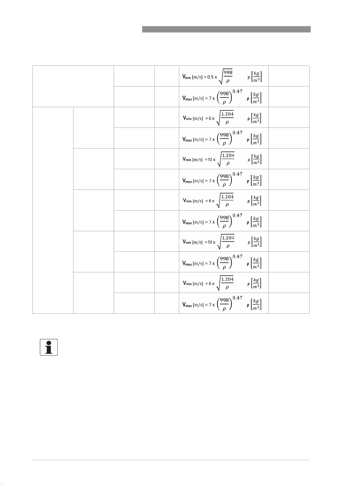
The devices are rated for the following flow velocities:
OPTISWIRL 4200
Liquids:
DN15...DN300
Gases and
steam:
DN15 V
DN15C V
DN25 V
DN25C V
V
: 0.25 m/s 0.8 ft/s 1
min
V
: 10 m/s 32 ft/s 2
max
: 3 m/s 10 ft/s 1
min
V
: 45 m/s 147 ft/s 2
max
: 3 m/s 10 ft/s 1
min
V
: 55 m/s 180 ft/s 2
max
: 2 m/s 6.6 ft/s 1
min
V
: 70 m/s 229 ft/s 2
max
: 2 m/s 6.6 ft/s 1
min
V
: 80 m/s 262 ft/s 2
max
DN40...
DN300
V
: 2 m/s 6.6 ft/s 1
min
V
: 80 m/s 262 ft/s 2
max
1 Use the larger value, according to the amount.
2 Use the smaller value, according to the amount.
INFORMATION!
DN15C and DN25C have a robust flow sensor (signal pick-up) for harsh measuring conditions
and higher maximum velocity compared to the standard version.
8
www.krohne.com 08/2016 - 4003930803 - MA OPTISWIRL 4200 R03 en
Page 9

OPTISWIRL 4200
1.3 Certifications
CE marking
The device fulfils the statutory requirements of the following EU directives:
• Pressure equipment directive
• EMC directive
• Devices for use in hazardous areas: ATEX directive
as well as
• EN 61010
• NAMUR recommendations NE 21 and NE 43
SAFETY INSTRUCTIONS
1
The manufacturer certifies successful testing of the product by applying the CE marking.
A CE declaration of conformity regarding the directives in question and the associated
harmonised standards can be downloaded from our internet site.
DANGER!
For devices used in hazardous areas, additional safety notes apply; please refer to the Ex
documentation.
www.krohne.com08/2016 - 4003930803 - MA OPTISWIRL 4200 R03 en
9
Page 10

1
SAFETY INSTRUCTIONS
1.4 Safety instructions from the manufacturer
1.4.1 Copyright and data protection
The contents of this document have been created with great care. Nevertheless, we provide no
guarantee that the contents are correct, complete or up-to-date.
The contents and works in this document are subject to copyright. Contributions from third
parties are identified as such. Reproduction, processing, dissemination and any type of use
beyond what is permitted under copyright requires written authorisation from the respective
author and/or the manufacturer.
The manufacturer tries always to observe the copyrights of others, and to draw on works created
in-house or works in the public domain.
The collection of personal data (such as names, street addresses or e-mail addresses) in the
manufacturer's documents is always on a voluntary basis whenever possible. Whenever
feasible, it is always possible to make use of the offerings and services without providing any
personal data.
OPTISWIRL 4200
We draw your attention to the fact that data transmission over the Internet (e.g. when
communicating by e-mail) may involve gaps in security. It is not possible to protect such data
completely against access by third parties.
We hereby expressly prohibit the use of the contact data published as part of our duty to publish
an imprint for the purpose of sending us any advertising or informational materials that we have
not expressly requested.
1.4.2 Disclaimer
The manufacturer will not be liable for any damage of any kind by using its product, including,
but not limited to direct, indirect or incidental and consequential damages.
This disclaimer does not apply in case the manufacturer has acted on purpose or with gross
negligence. In the event any applicable law does not allow such limitations on implied warranties
or the exclusion of limitation of certain damages, you may, if such law applies to you, not be
subject to some or all of the above disclaimer, exclusions or limitations.
Any product purchased from the manufacturer is warranted in accordance with the relevant
product documentation and our Terms and Conditions of Sale.
The manufacturer reserves the right to alter the content of its documents, including this
disclaimer in any way, at any time, for any reason, without prior notification, and will not be liable
in any way for possible consequences of such changes.
10
www.krohne.com 08/2016 - 4003930803 - MA OPTISWIRL 4200 R03 en
Page 11

OPTISWIRL 4200
1.4.3 Product liability and warranty
The operator shall bear responsibility for the suitability of the device for the specific purpose.
The manufacturer accepts no liability for the consequences of misuse by the operator. Improper
installation or operation of the devices (systems) will cause the warranty to be void. The
respective "Standard Terms and Conditions" which form the basis for the sales contract shall
also apply.
1.4.4 Information concerning the documentation
To prevent any injury to the user or damage to the device it is essential that you read the
information in this document and observe applicable national standards, safety requirements
and accident prevention regulations.
If this document is not in your native language and if you have any problems understanding the
text, we advise you to contact your local office for assistance. The manufacturer can not accept
responsibility for any damage or injury caused by misunderstanding of the information in this
document.
This document is provided to help you establish operating conditions, which will permit safe and
efficient use of this device. Special considerations and precautions are also described in the
document, which appear in the form of icons as shown below.
SAFETY INSTRUCTIONS
1
www.krohne.com08/2016 - 4003930803 - MA OPTISWIRL 4200 R03 en
11
Page 12
1
SAFETY INSTRUCTIONS
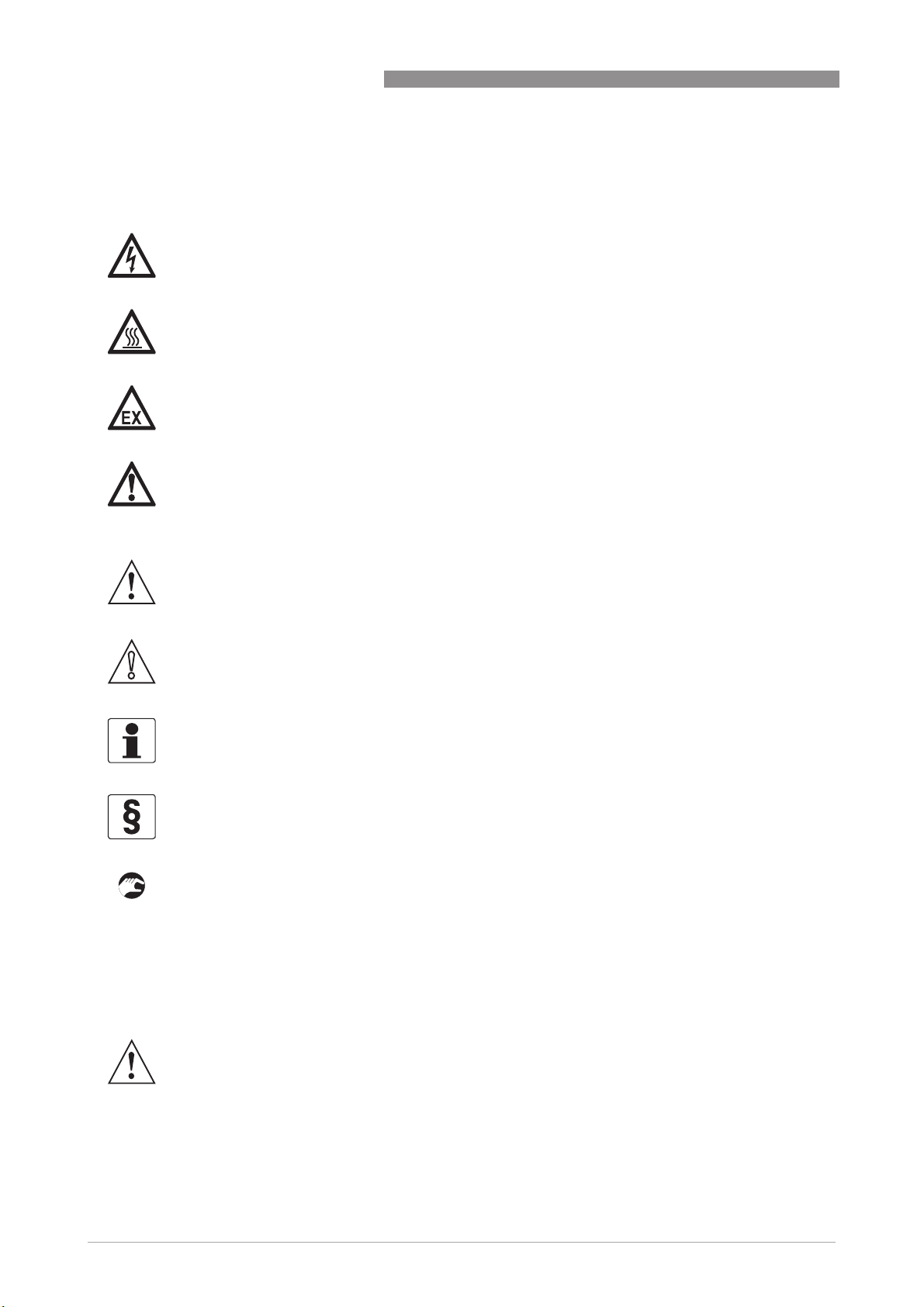
1.4.5 Warnings and symbols used
Safety warnings are indicated by the following symbols.
DANGER!
This warning refers to the immediate danger when working with electricity.
DANGER!
This warning refers to the immediate danger of burns caused by heat or hot surfaces.
DANGER!
This warning refers to the immediate danger when using this device in a hazardous atmosphere.
DANGER!
These warnings must be observed without fail. Even partial disregard of this warning can lead to
serious health problems and even death. There is also the risk of seriously damaging the device
or parts of the operator's plant.
OPTISWIRL 4200
WARNING!
Disregarding this safety warning, even if only in part, poses the risk of serious health problems.
There is also the risk of damaging the device or parts of the operator's plant.
CAUTION!
Disregarding these instructions can result in damage to the device or to parts of the operator's
plant.
INFORMATION!
These instructions contain important information for the handling of the device.
LEGAL NOTICE!
This note contains information on statutory directives and standards.
• HANDLING
HANDLING
HANDLINGHANDLING
This symbol designates all instructions for actions to be carried out by the operator in the
specified sequence.
i RESULT
RESULT
RESULTRESULT
This symbol refers to all important consequences of the previous actions.
1.5 Safety instructions for the operator
12
WARNING!
In general, devices from the manufacturer may only be installed, commissioned, operated and
maintained by properly trained and authorized personnel.
This document is provided to help you establish operating conditions, which will permit safe and
efficient use of this device.
www.krohne.com 08/2016 - 4003930803 - MA OPTISWIRL 4200 R03 en
Page 13
OPTISWIRL 4200
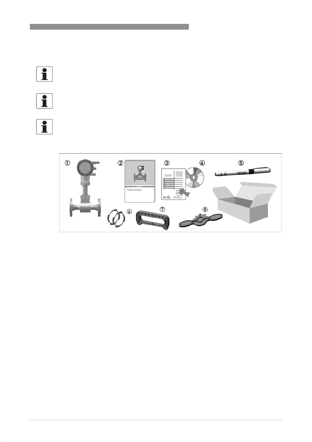
2.1 Scope of delivery
INFORMATION!
Inspect the packaging carefully for damages or signs of rough handling. Report damage to the
carrier and to the local office of the manufacturer.
INFORMATION!
Do a check of the packing list to make sure that you have all the elements given in the order.
INFORMATION!
Look at the device nameplate to ensure that the device is delivered according to your order.
Check for the correct supply voltage printed on the nameplate.
DEVICE DESCRIPTION
2
Figure 2-1: Scope of delivery
1 Measuring device in ordered version
2 Product documentation
3 Certificates, calibration report and parameter data sheet
4 CD with complete documentation
5 Bar magnet
6 Centering rings (only for sandwich devices)
7 Handle to pull off the display
8 Key for opening the front and rear cover
2.2 Device versions
The devices are delivered in the following variants:
• Signal converter with display
• Flow sensor in flanged design, flow sensor F
• Flow sensor in sandwich design, flow sensor S
• Remote version - Flow sensor with separated remote signal converter
• Dual version with two flow sensors and two signal converters
The following designs are available as options:
• With pressure sensor - with or without shut-off valve
• Flange version, flow sensor with single reduction F1R
• Flange version, flow sensor with double reduction F2R
www.krohne.com08/2016 - 4003930803 - MA OPTISWIRL 4200 R03 en
13
Page 14
2
DEVICE DESCRIPTION
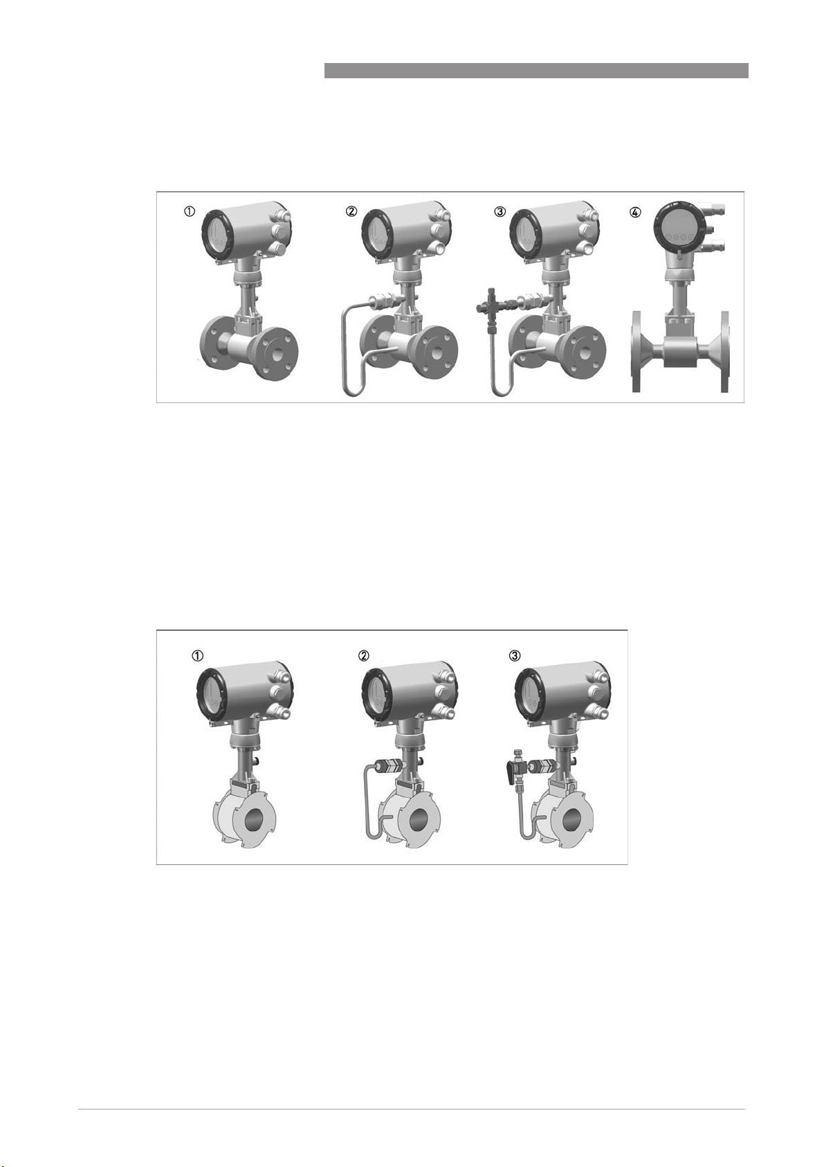
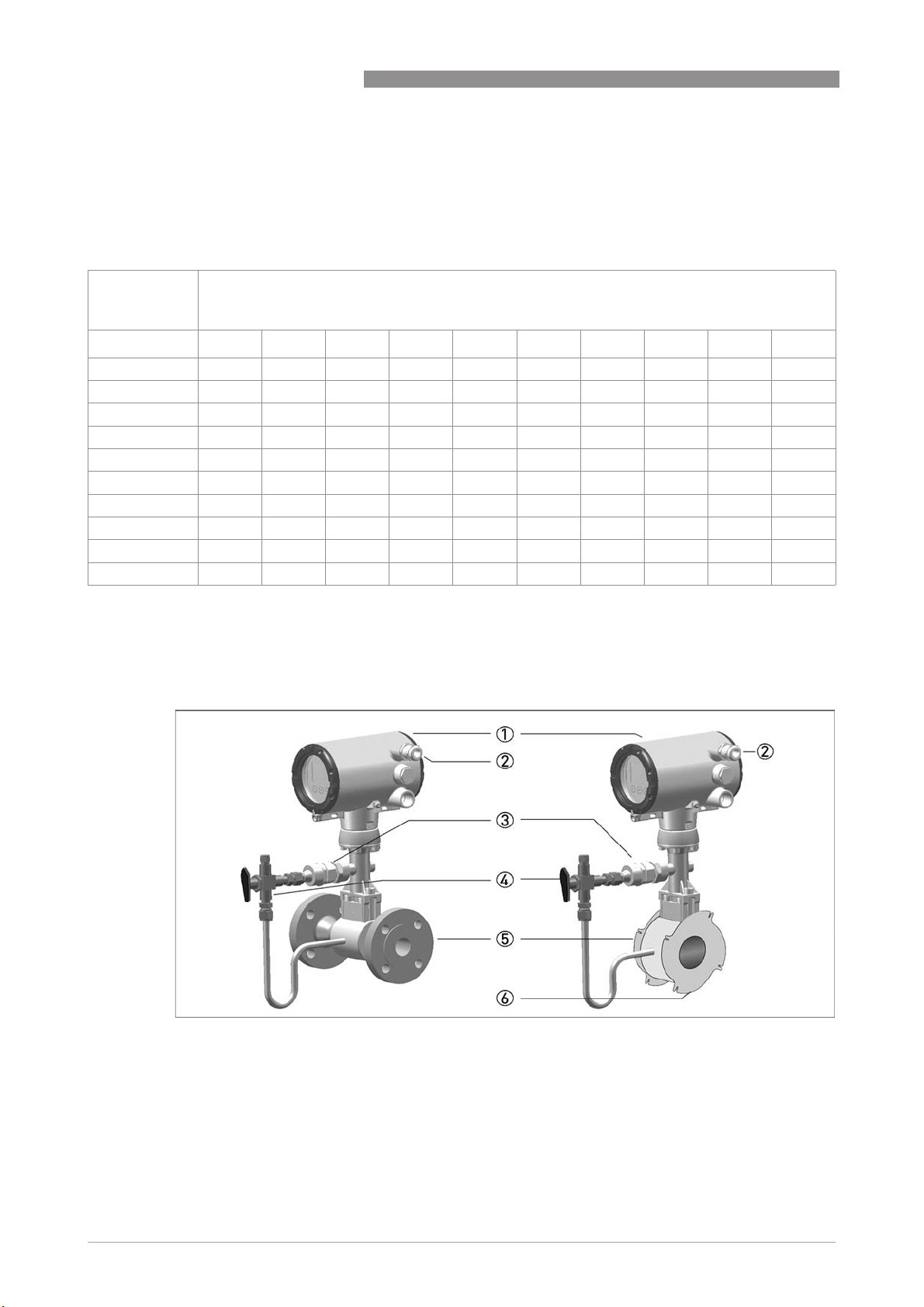
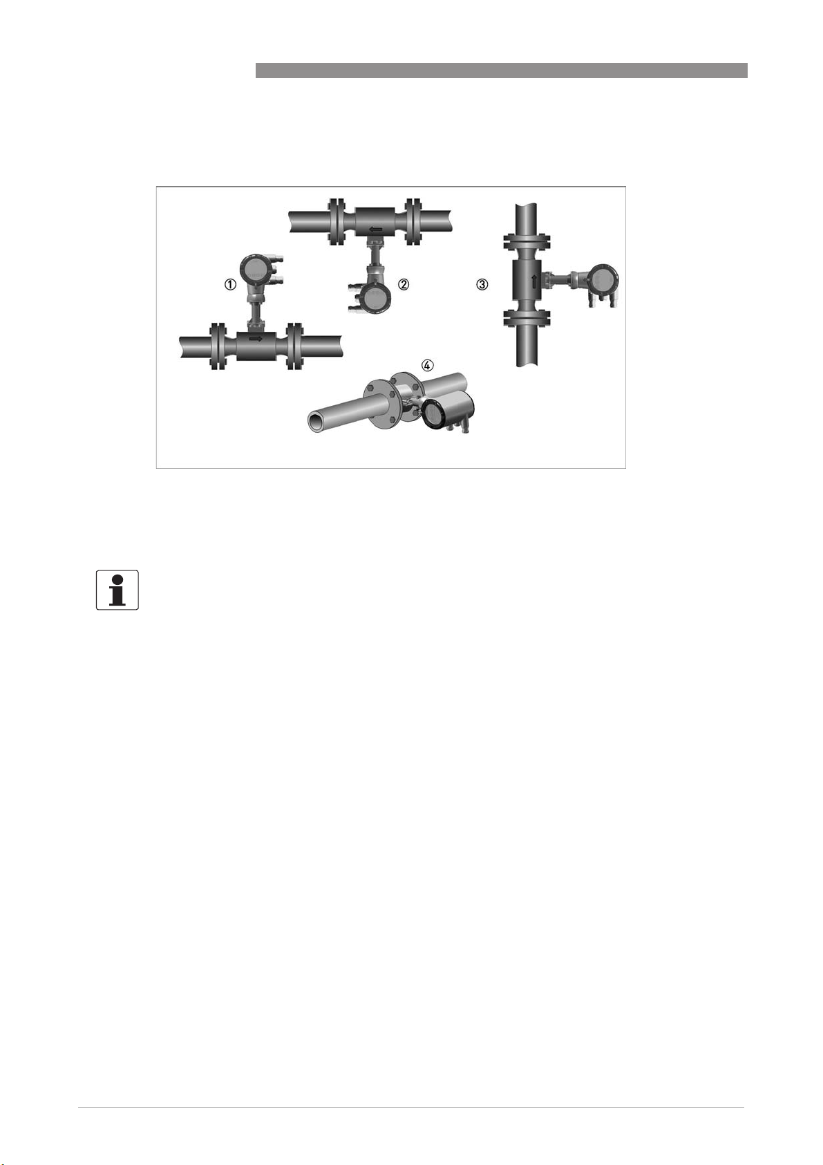
2.2.1 Devices with connection flange
Figure 2-2: Flanged devices with display
1 Version with temperature sensor
2 Version with temperature sensor and optional pressure sensor
3 Version with temperature sensor, optional pressure sensor and shut-off valve
4 Version with temperature sensor, flow sensor with integrated reducer
OPTISWIRL 4200
2.2.2 Devices in sandwich version
The sandwich version features 2 centering rings to aid with installation.
Figure 2-3: Sandwich versions with display
1 Version with temperature sensor
2 Version with temperature sensor and optional pressure sensor
3 Version with temperature sensor, optional pressure sensor and shut-off valve
14
www.krohne.com 08/2016 - 4003930803 - MA OPTISWIRL 4200 R03 en
Page 15
OPTISWIRL 4200
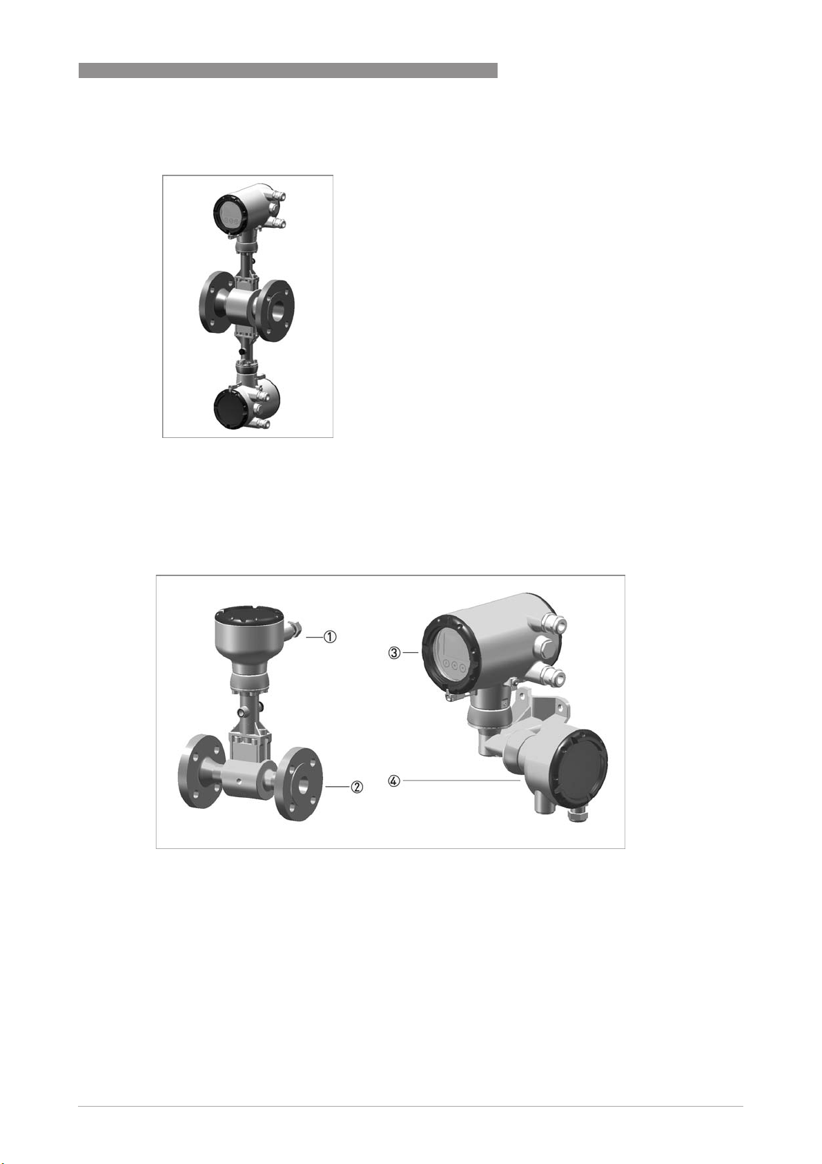
2.2.3 Dual version and twofold reliability
DEVICE DESCRIPTION
2
This is a genuine redundant system with two
independent flow sensors and two signal
converters.
This provides twofold functional reliability and
availability of the measurement. This variant
is ideally suited for measurements in multiproduct pipelines. In such pipelines, two
different products are moved through one
after the other. One signal converter can be
programmed for one product, and the other
signal converter for the other product.
2.2.4 Remote version
Figure 2-4: Remote version
1 Flow sensor connection box
2 Flow sensor
3 Signal converter
4 Wall mount bracket connection box
With the remote version, the flow sensor and signal converter are installed separately in
different places. The 6-pin, shielded connection cable is available with a length up to 50 m /
164 ft.
www.krohne.com08/2016 - 4003930803 - MA OPTISWIRL 4200 R03 en
15
Page 16
2
DEVICE DESCRIPTION
2.2.5 Devices with integrated nominal diameter reduction
The device versions F1R and F2R offer an integrated nominal diameter reduction up to two
nominal diameter sizes to assure best results in accuracy and optimum measuring ranges; even
in pipelines with large diameters, which have been designed for a low pressure loss.
OPTISWIRL 4200
Nominal
Nominal size of process connections
diameter of flow
sensor
DN15 DN25 DN40 DN50 DN80 DN100 DN150 DN200 DN250 DN300
DN15 StV
DN25 - StV
DN40 --StV
DN50 ---StV
DN80 ----StV
DN100 -----StV
DN150 ------StV
DN200 -------StV
DN250 --------StV
DN300 ---------StV
1 Standard version
1
F1RF2R-------
1
F1RF2R------
1
F1RF2R-----
1
F1RF2R----
1
F1RF2R---
1
F1R F2R - -
1
F1R F2R -
1
F1R F2R
1
F1R
1
2.2.6 Device description
16
Figure 2-5: Device description
1 Signal converter
2 Cable feed through
3 Pressure sensor, optional
4 Shut-off valve, optional
5 Flow sensor
6 Centering ring
www.krohne.com 08/2016 - 4003930803 - MA OPTISWIRL 4200 R03 en
Page 17

OPTISWIRL 4200
2.2.7 Free air delivery measurement - FAD (optional)
To create compressed air, a compressor draws in air from the ambient atmosphere,
compresses it and delivers it at the required pressure. Since the ambient atmosphere also
contains water vapour, what the compressor draws in is a mixture of air and water vapour. In
addition to the moisture in the air, the ambient temperature and pressure conditions on the inlet
side and the process conditions on the outlet side also influence compressor capacity.
That is why most manufacturers specify compressor capacity as free air delivery at standard
intake conditions. To compare the capacity of different compressors or to compare the capacity
of a compressor at different points in time, the measurement of the air conveyed by the
compressor must be purged of the influences of the process and of the environment and
converted to these standardised suction conditions.
The vortex flowmeter with optional FAD function (FAD - Free Air Delivery) can measure the free
air delivery online, regardless of its function as standard flowmeter. For this the device needs
the process and ambient conditions, as well as the compressor data. When installed on the
outlet side, it measures the air volume generated by the compressor and the process conditions.
The menu-driven, user-friendly software prompts the operator to enter the following values:
DEVICE DESCRIPTION
2
• Ambient temperature (inlet)
• Atmospheric pressure (inlet)
• Air humidity (inlet and outlet)
• Motor speed (rated speed and actual speed)
• Pressure loss of the air filter
The FAD value is calculated from the measured and entered parameters using the vapour and
compressibility tables stored in the measuring device.
INFORMATION!
FAD measurement is an optional feature which can be unlocked in menu "C6.3 Extras".
Please contact the manufacturer to obtain the four digit code required to enable this feature.
For programming example refer to Settings for free air delivery measurement - FAD on page 83
.
www.krohne.com08/2016 - 4003930803 - MA OPTISWIRL 4200 R03 en
17
Page 18

2
DEVICE DESCRIPTION
2.2.8 Gross heat quantity calculation (optional)
This feature enables the calculation of the heat flow volume in systems where hot water,
saturated or superheated steam is used for heating.
The determination of gross heat is based on the relation between the temperature-dependent
enthalpy of steam and mass flow. The enthalpy tables are permanently programmed in the
device memory.
The calculated density-compensated mass flow is multiplied by the correct enthalpy in order to
obtain gross heat flow.
OPTISWIRL 4200
Gross power [Q
The absolute hot water and steam consumption, as well as the energy, can be monitored
internally via a totalizer, which enables an integration of the measured heat flow over time.
] = mass flow [Qm] x enthalpy [H]
H
INFORMATION!
Gross heat quantity calculation is an optional feature, which can be unlocked in menu "C6.3
Extras". Please contact the manufacturer to obtain the four digit code required to enable this
feature.
For programming example refer to Gross heat measurement on page 84
.
18
www.krohne.com 08/2016 - 4003930803 - MA OPTISWIRL 4200 R03 en
Page 19
OPTISWIRL 4200
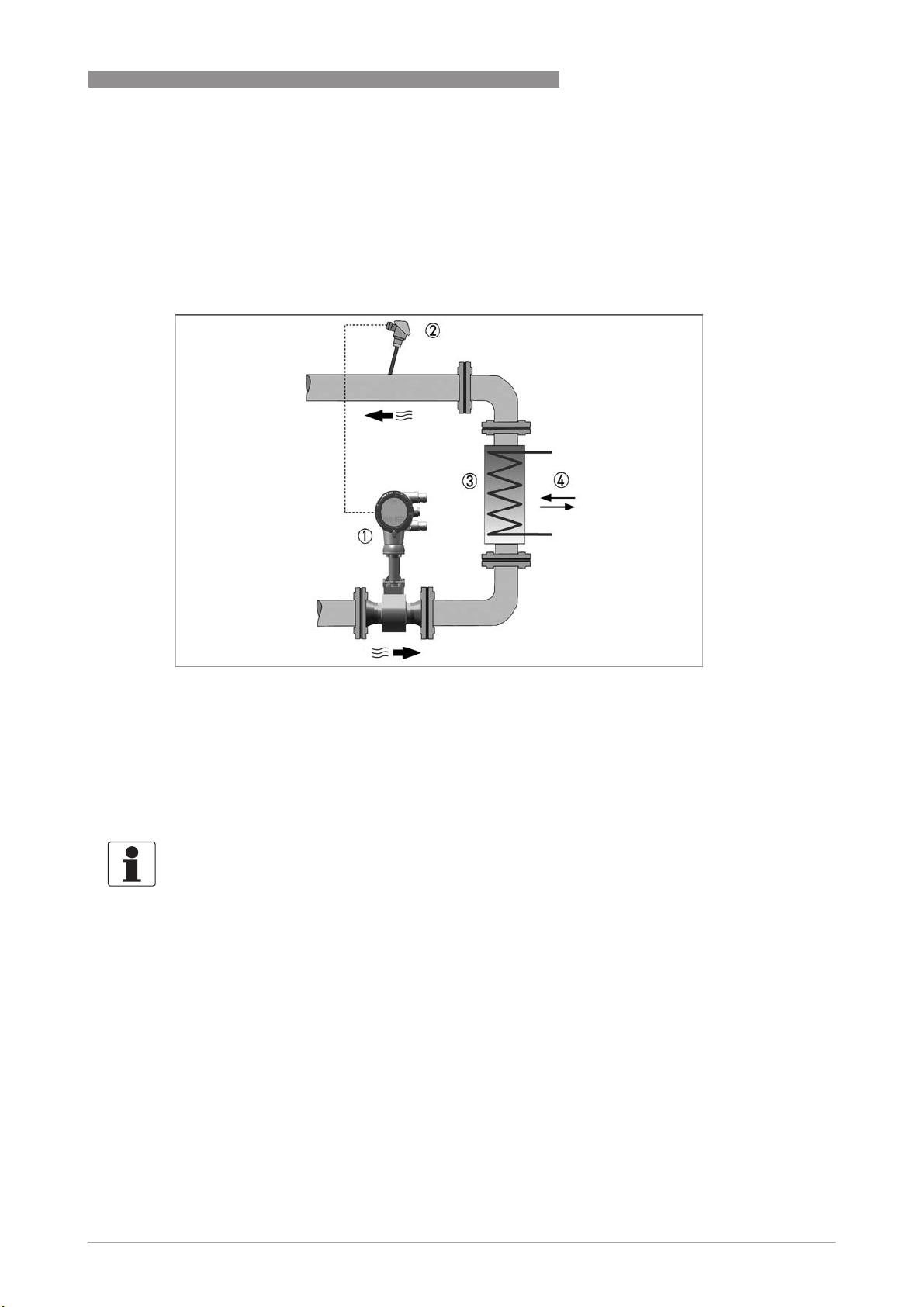
2.2.9 Net heat quantity calculation (optional)
When measuring the net heat, the energy consumption of steam and hot water can be exactly
determined. To do this, the vortex flowmeter is built into the inlet run of the plant component to
be measured. An additional temperature sensor is installed in the return flow and then
connected to the signal converter, either via an additional current input or via HART
DEVICE DESCRIPTION
®
.
2
Figure 2-6: Measuring heat difference
1 Flowmeter with built-in temperature sensor
2 Temperature sensor
3 Heat exchanger
4 Heat flow
The measuring device can now determine the gross heat and measure the net heat from the
temperature difference determined by the second temperature sensor.
INFORMATION!
Net heat quantity calculation is an optional feature which can be unlocked in menu "C6.3 Extras".
Please contact the manufacturer to obtain the four digit code required to enable this feature.
For programming examples refer to Net heat measurement on page 85
.
www.krohne.com08/2016 - 4003930803 - MA OPTISWIRL 4200 R03 en
19
Page 20
2
DEVICE DESCRIPTION
2.2.10 Dual seal
To comply with the requirements of ANSI/ISA 12.27.01 "Requirements for Process Sealing
Between Electrical Systems and Flammable or Combustible Process Fluids", a membrane vent
is integrated in the neck of the device. This vent is located between the primary seal (process)
and the secondary seal (electronics compartment) and works to prevent pressure build-up in the
device neck, thus preventing product from penetrating the electronics compartment in the
unlikely event of a leak in the primary seal.
OPTISWIRL 4200
Figure 2-7: Dual Seal
1 Membrane vent
The seal between the pick-up and the measuring tube is considered as the primary seal. The
material used for this is always the same as that used for the measuring tube itself (e.g.
®
1.4435/316L for measuring tube made of stainless steel 1.4404/316L or Hastelloy
®
measuring tube made of Hastelloy
C22). When selecting the material, corrosion resistance
C276 for
depending on process parameters (product, temperature) must be taken into account.
By using the membrane vent, all requirements for a "DUAL SEAL" version in terms of the above
mentioned standards are met.
• It protects the electronics from the process media.
• Any leak in the primary seal can be detected.
Even though there is no reason to expect the seal to fail, regular visual checks should still be
carried out to detect any possible leak as early as possible.
In the event of a leak, contact the manufacturer's service department to service or replace the
device.
20
www.krohne.com 08/2016 - 4003930803 - MA OPTISWIRL 4200 R03 en
Page 21
OPTISWIRL 4200
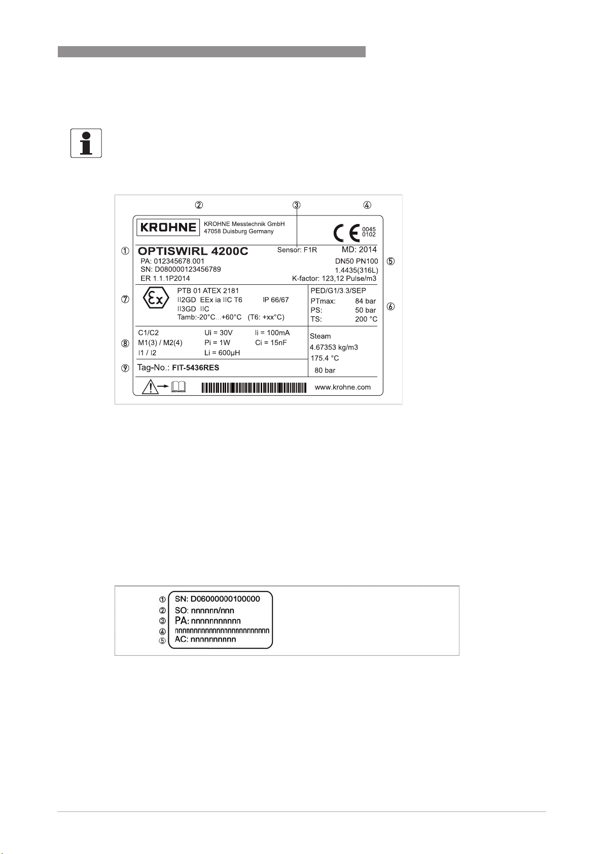
2.3 Nameplate
INFORMATION!
Check the device nameplate to ensure that the device is delivered according to your order. Check
for the correct supply voltage printed on the nameplate.
DEVICE DESCRIPTION
2
Figure 2-8: Example of nameplate
1 Meter type
2 Manufacturer
3 Flow sensor
S - Sandwich
F - Flange
F1R - Flange, single reduction
F2R - Flange, double reduction
4 Notified bodies for PED & ATEX (only available if this option was ordered)
5 Connection data: nominal diameter and pressure rating
6 PED data
7 Ex data (only available if this option was ordered)
8 Electrical connection data
9 Tag no. - Measuring point identifier
Figure 2-9: Example of nameplate
1 Serial number
2 Order number
3 Production order number
4 Type code
5 Article code
www.krohne.com08/2016 - 4003930803 - MA OPTISWIRL 4200 R03 en
21
Page 22
3
INSTALLATION
3.1 General notes on installation
INFORMATION!
Inspect the packaging carefully for damages or signs of rough handling. Report damage to the
carrier and to the local office of the manufacturer.
INFORMATION!
Do a check of the packing list to make sure that you have all the elements given in the order.
3.2 Storage
• Store the device in a dry, dust-free location.
• Avoid extended direct exposure to the sun.
• Store the device in the original packaging.
• The permissible storage temperature for standard devices is -40...+85°C / -40...+185°F.
OPTISWIRL 4200
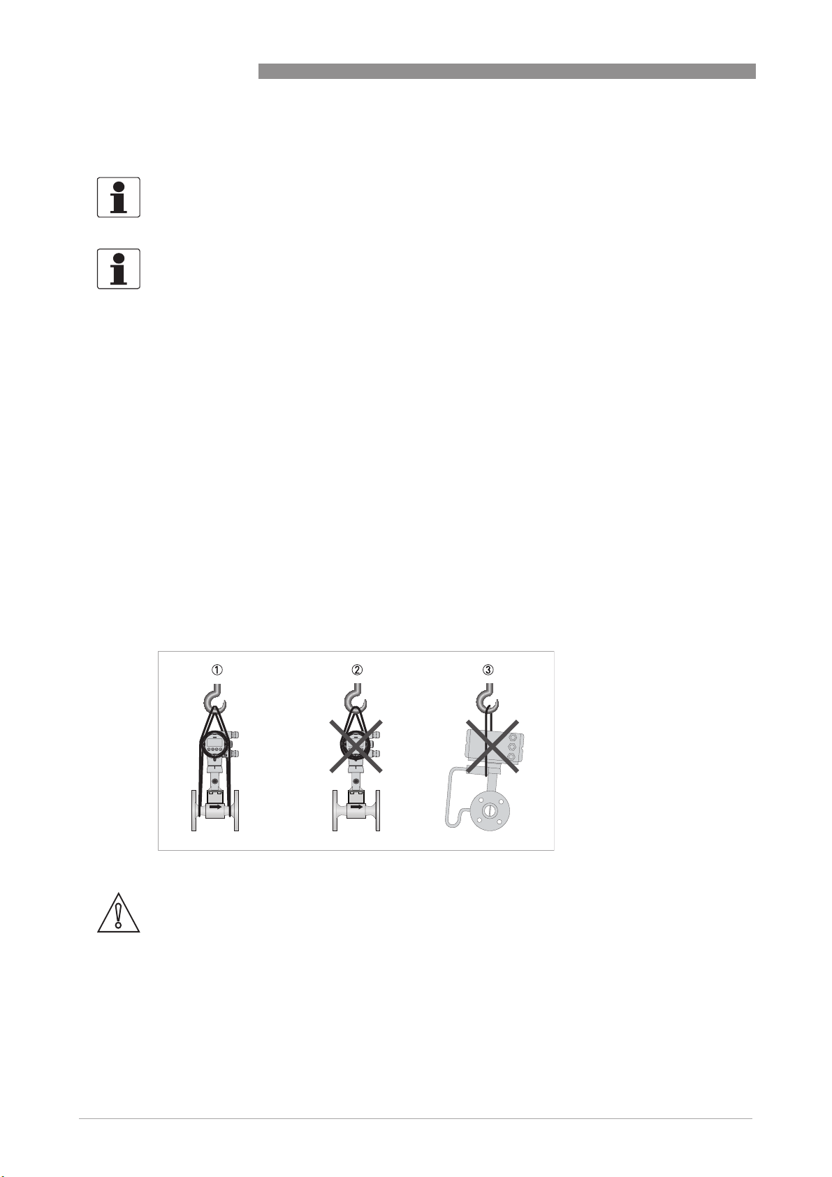
3.3 Transport
• Use lifting straps wrapped around both process connections for transport.
• Do not lift measuring devices by the signal converter housing for transport.
• Never lift the measuring device by the pressure sensor.
• Do not use lifting chains as they may damage the housing.
Figure 3-1: Transport instructions
CAUTION!
Non-secured devices can pose risk of injury. The centre of mass of the device is often higher
than the point at which the lifting straps are attached.
Prevent the measuring device from sliding or rotating accidentally.
22
www.krohne.com 08/2016 - 4003930803 - MA OPTISWIRL 4200 R03 en
Page 23
OPTISWIRL 4200
3.4 Installation conditions
INFORMATION!
For accurate volumetric flow measurement the measuring device needs a completely filled pipe
and a fully developed flow profile.
CAUTION!
Any vibration will distort the measuring result. That is why any vibrations in the pipeline must be
prevented through suitable measures.
CAUTION!
Procedures to carry out before installing the device:
•
Nominal diameter of connection pipe flange = nominal flange diameter of pipe!
•
Use flanges with smooth holes, e.g. welding neck flanges.
•
Align carefully the holes of the connecting flange and the flowmeter flange.
•
Check the compatibility of the gasket material with the process product.
•
Make sure that the gaskets are arranged concentrically. The flange gaskets must not project
into the pipe cross-section.
•
The flanges have to be concentric.
•
There must not be any pipe bends, valves, flaps or other internals in the immediate inlet run.
•
Devices in sandwich version may only be installed using centering rings.
•
Never install the device directly behind piston compressors or rotary piston meters.
•
Do not lay signal cables directly next to cables for the power supply.
•
At product temperatures or ambient temperatures >+65°C / +149°F, a connection cable and
cable glands with a minimum service temperature of +80
INSTALLATION
°
C / +176°F must be used.
3
INFORMATION!
If there is a risk of water hammers in steam networks, appropriate condensate separators must
be installed. Suitable measures must be taken to avoid water cavitation if it is a possible risk.
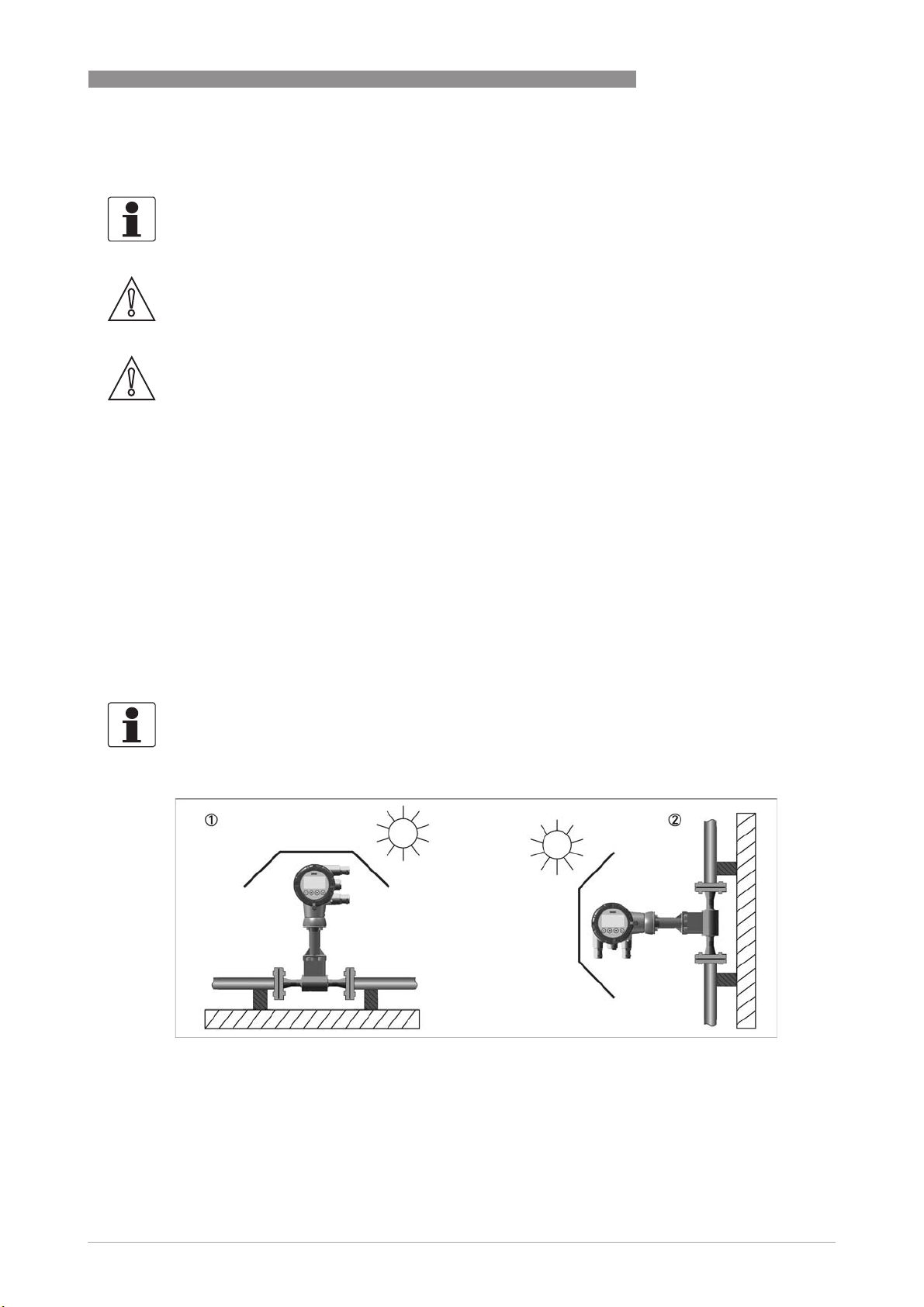
Sunshades
Figure 3-2: Installation recommendations
1 Horizontal mounting
2 Vertical mounting
The meter MUST be protected from strong sunlight.
A sunshade is available from the manufacturer as an option.
www.krohne.com08/2016 - 4003930803 - MA OPTISWIRL 4200 R03 en
23
Page 24
3
INSTALLATION
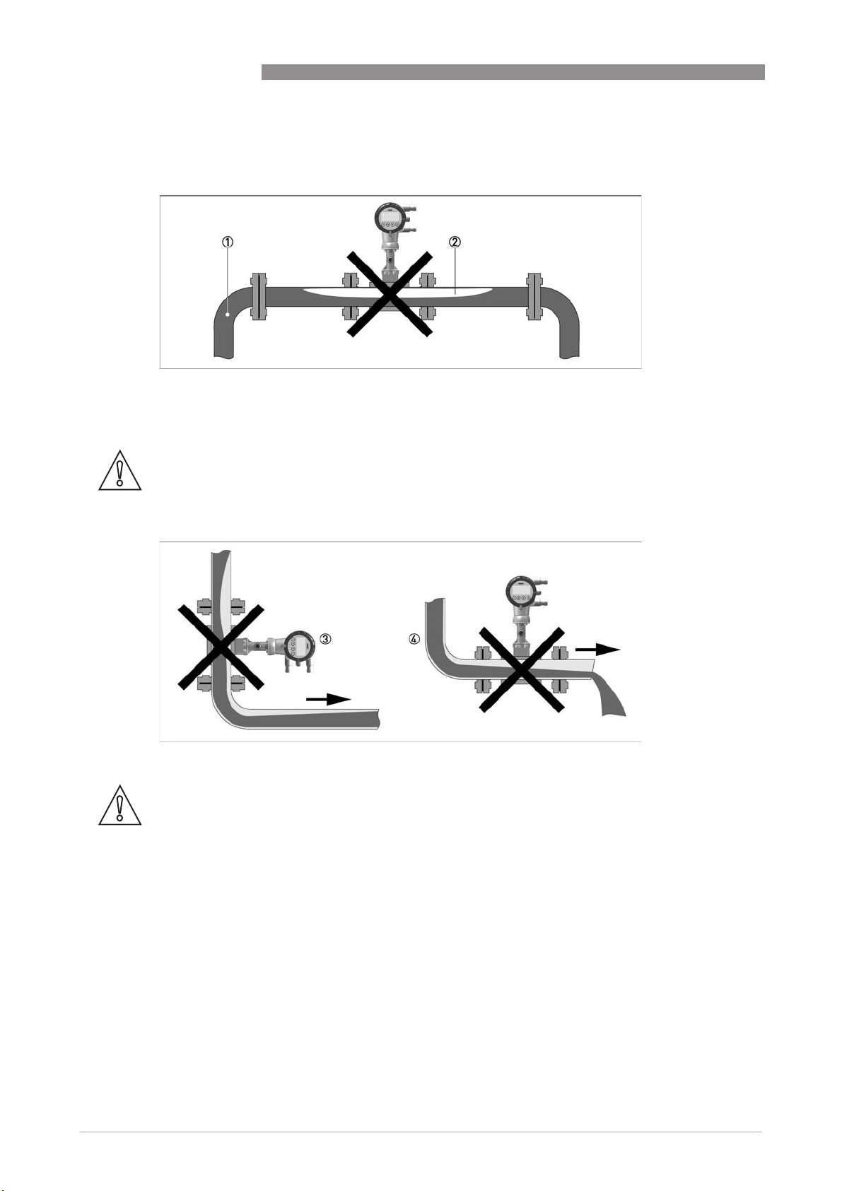
3.4.1 Prohibited installation when measuring liquids
Figure 3-3: Upper pipe bend
CAUTION!
Prohibited: Installing the device in an upper pipe bend 1, because there is a risk of gas bubbles
2 forming. Gas bubbles can lead to pressure surges and inaccurate measurement.
OPTISWIRL 4200
24
Figure 3-4: Downstream pipe and outlet
CAUTION!
Installing the device in a downstream pipe 3 or upstream pipe of an outlet 4. There is the risk of
partially filled pipes leading to inaccurate measurements.
www.krohne.com 08/2016 - 4003930803 - MA OPTISWIRL 4200 R03 en
Page 25
OPTISWIRL 4200
3.4.2 Prohibited installation when measuring steam and gases
1 Lower pipe bends
2 Condensate
DANGER!
Prohibited: Installing the device in a lower pipe bend 1, because there is a risk of condensate
forming 2.
Condensate can lead to cavitation and inaccurate measurement. Under certain circumstances
the device can be destroyed and the measured medium can leak.
INSTALLATION
3
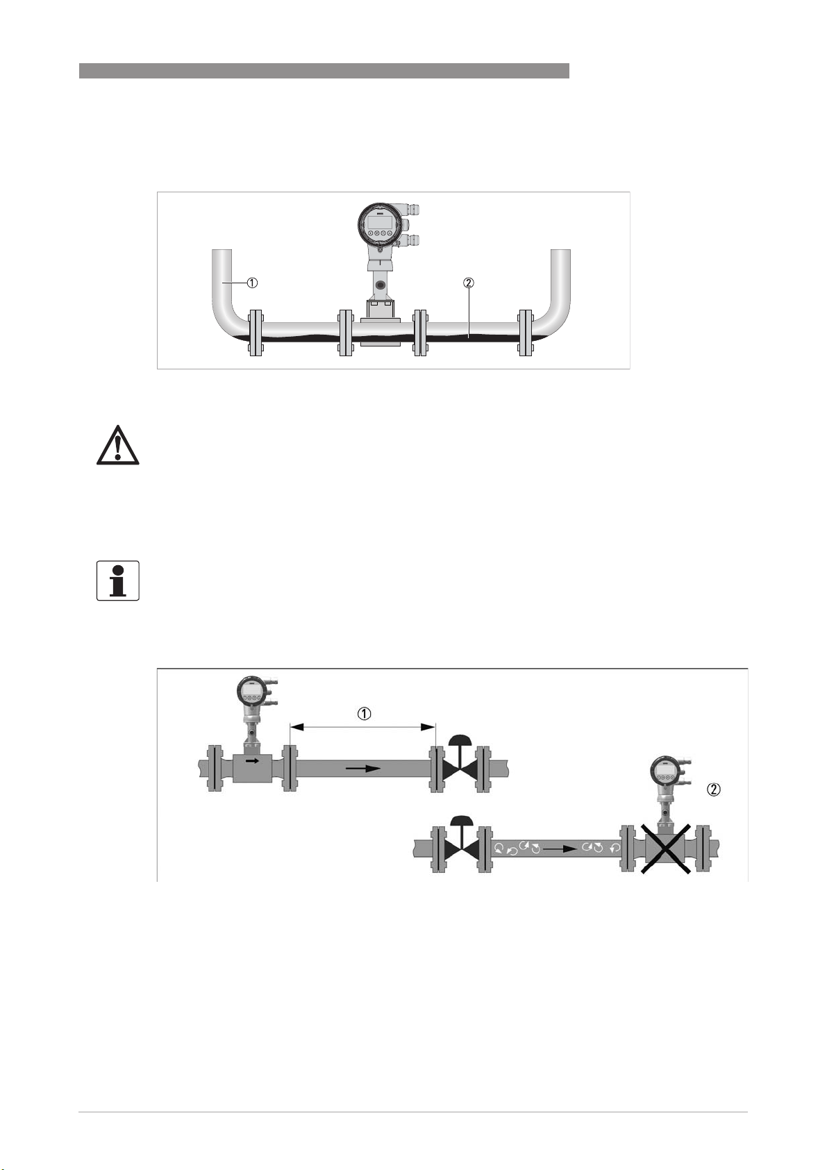
3.4.3 Pipelines with control valve
INFORMATION!
To ensure smooth and correct measurement, the manufacturer recommends not installing the
measuring device downstream from a control valve. This would run the risk of vortex formation,
which would distort the measuring result.
Figure 3-5: Pipeline with control valve
1 Recommended: installing the device before the control valve at a distance of ≥ 5 DN
2 Not recommended: Installing the flowmeter directly downstream of control valves, due to vortex formation.
www.krohne.com08/2016 - 4003930803 - MA OPTISWIRL 4200 R03 en
25
Page 26
3
INSTALLATION
3.4.4 Preferred mounting position
Preferred mounting position
OPTISWIRL 4200
Figure 3-6: Mountig position
1 Above a horizontal pipe
2 Underneath a horizontal pipe (not permitted with lines at risk of condensate forming)
3 On a vertical pipe
4 Horizontal pipeline with signal converter-orientation 90° to the side
INFORMATION!
Depending on the installation position, you may have to rotate the display and/or the connection
housing.
26
www.krohne.com 08/2016 - 4003930803 - MA OPTISWIRL 4200 R03 en
Page 27
OPTISWIRL 4200
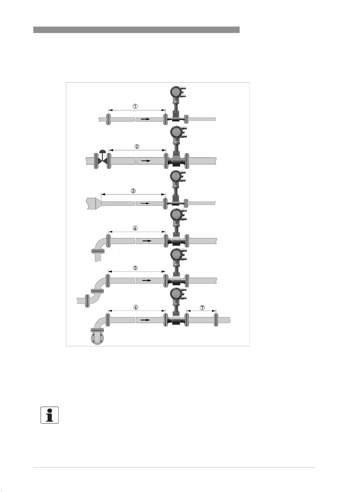
3.5 Minimum inlet sections
INSTALLATION
3
Figure 3-7: Inlet sections
1 General inlet section without disturbing flow ≥ 15 DN
2 After a control valve ≥ 50 DN
3 After a pipe diameter reduction ≥ 20 DN
4 After a single bend 90° ≥ 20 DN
5 After a double bend 2x90° ≥ 30 DN
6 After a double three-dimensional bend 2x90° ≥ 40 DN
7 Outlet section: >5 DN
INFORMATION!
The nominal diameter of the flange is significant for the determination of the minimum inlet and
outlet sections for the nominal diameter reduced versions of vortex flowmeter versions F1R and
F2R.
www.krohne.com08/2016 - 4003930803 - MA OPTISWIRL 4200 R03 en
27
Page 28
3
INSTALLATION
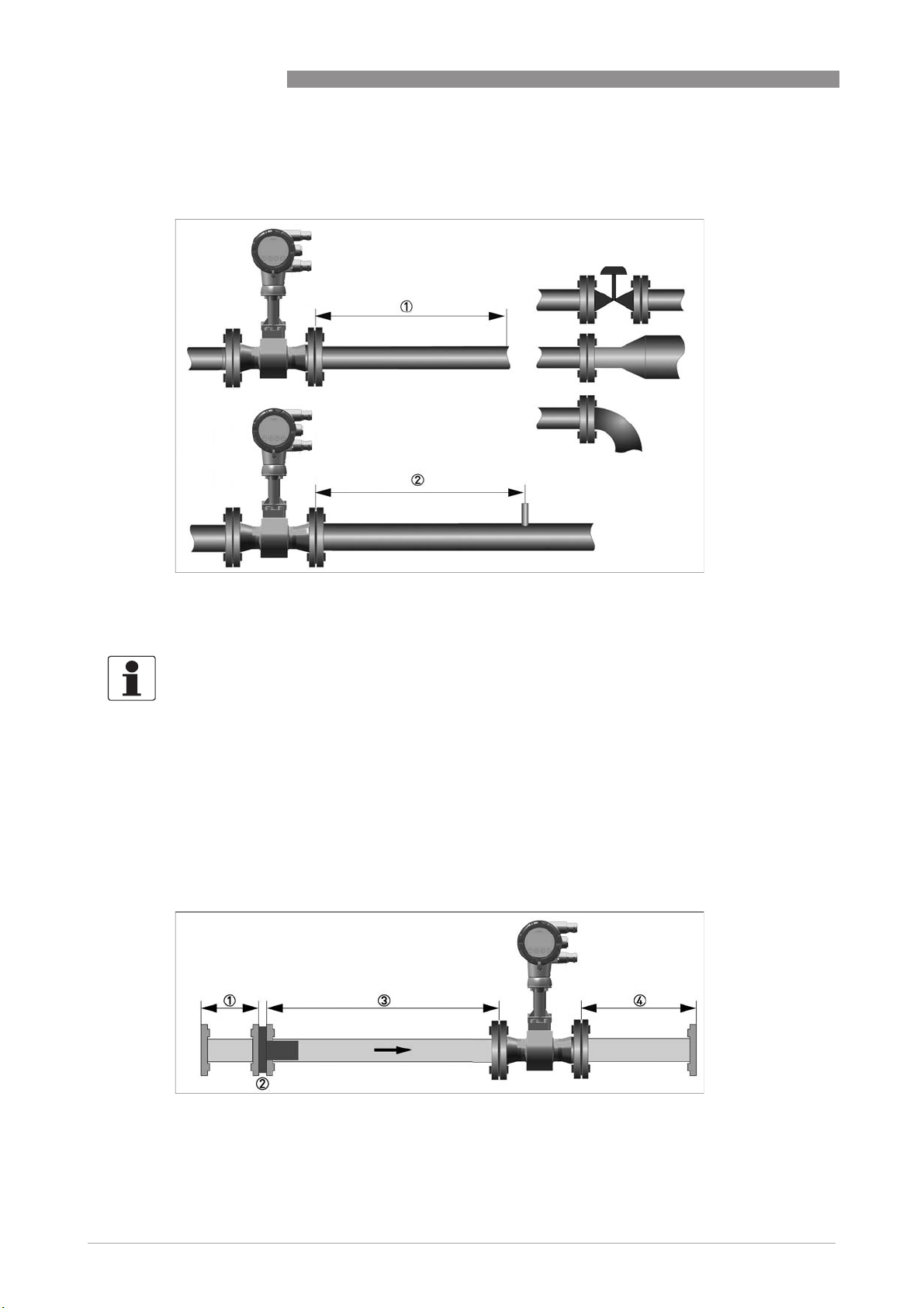
3.6 Minimum outlet sections
OPTISWIRL 4200
Figure 3-8: Minimum outlet sections
1 Upstream of pipe expanders, pipe bends, control valves, etc. ≥ 5 DN
2 Upstream of measuring points ≥ 5 DN
INFORMATION!
The interior of the pipe at the metering points must be free of burrs and other flow impediments.
The measuring device has an internal temperature sensor. The distance from external
temperature measuring points must be ≥ 5 DN. Use flow sensors that are as short as possible to
avoid disturbances of the flow profile.
3.7 Flow straightener
If, due to the type of installation, the required inlet sections are not available, the manufacturer
recommends using flow straighteners. Flow straighteners are installed between two flanges
upstream of the device and shorten the required inlet section.
28
Figure 3-9: Flow straightener
1 Straight inlet section upstream of straightener ≥ 2 DN
2 Flow straightener
3 Straight pipe run between flow straightener and device ≥ 8 DN
4 Minimum straight outlet section ≥ 5 DN
www.krohne.com 08/2016 - 4003930803 - MA OPTISWIRL 4200 R03 en
Page 29
OPTISWIRL 4200
3.8 Installation
3.8.1 General installation notes
CAUTION!
Installation, assembly, start-up and maintenance may only be performed by appropriately
trained personnel. The regional occupational health and safety directives must always be
observed.
The following procedures have to be carried out before installing the device:
• Ensure that the gaskets have the same diameter as the pipelines.
• Note the correct flow direction for the device. This is indicated by an arrow on the neck of the
flow sensor.
• On measuring points with varying thermal loads, the devices have to be mounted with stress
bolts (DIN 2510).
• Stress bolts or bolts and nuts are not included in the scope of delivery.
• Ensure that the measuring flange is concentrically fitted.
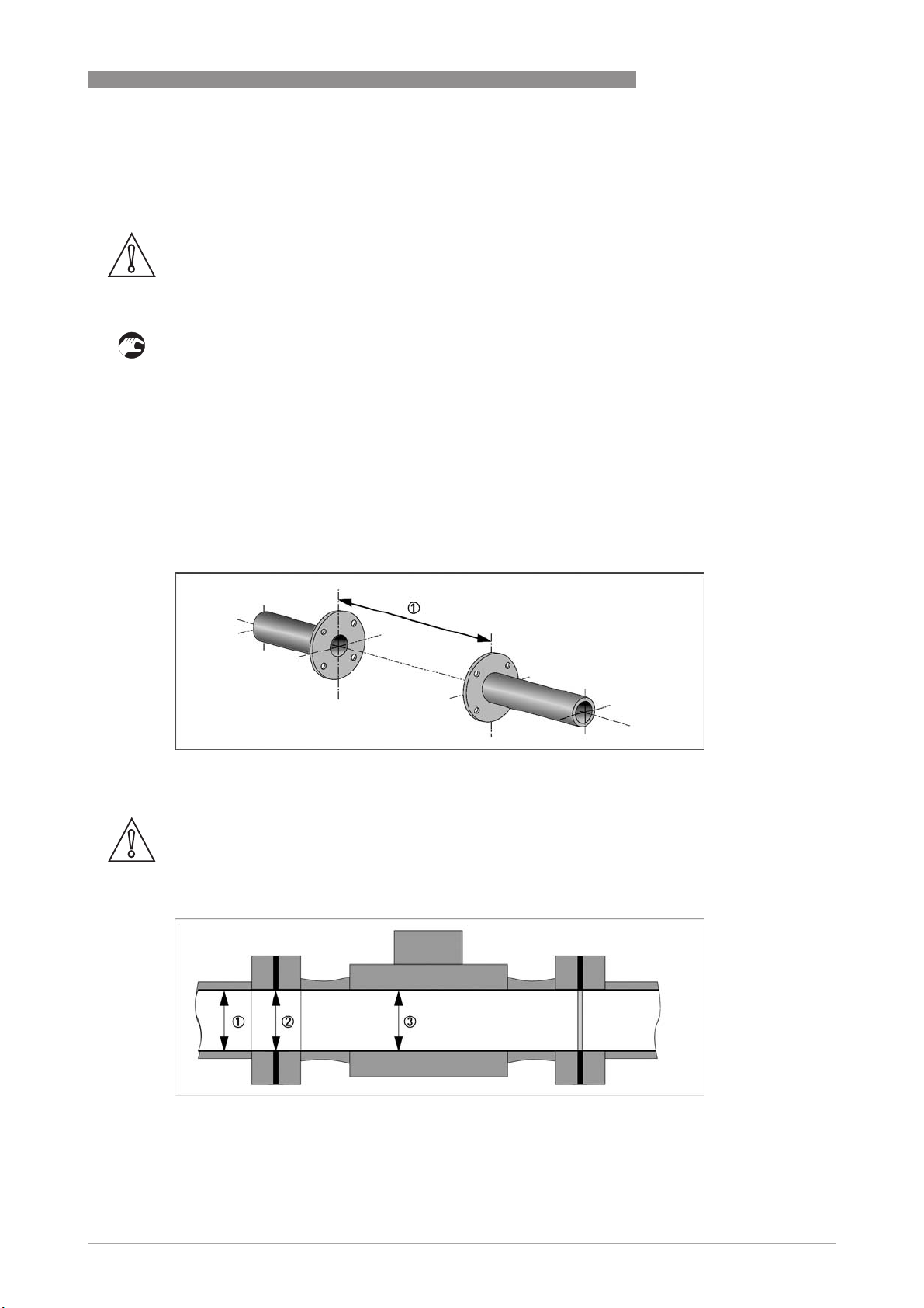
• Note the exact installation length of the measuring device when preparing the measuring
point.
INSTALLATION
3
Figure 3-10: Preparing the metering point
1 Installation length of measuring device + thickness of gaskets.
CAUTION!
The internal diameter of the pipelines, the flow sensor and the gaskets must match. The gaskets
may not protrude into the flow.
Figure 3-11: Inner diameter
1 Inner diameter of connection pipe
2 Inner diameter of flange and gasket
3 Inner diameter of flow sensor
www.krohne.com08/2016 - 4003930803 - MA OPTISWIRL 4200 R03 en
29
Page 30
3
INSTALLATION
3.8.2 Installing devices in sandwich design
OPTISWIRL 4200
Figure 3-12: Installation using centering ring
1 Flow sensor
2 Centering ring
3 Bolts with fixing nuts
4 Drill hole
5 Sealing
• Push the first bolt 3 through the hole 4 of both flanges.
• Screw on the nuts and washers to both ends of the bolt 3 but do not tighten them.
• Install the second bolt through the holes 4.
• Place the flow sensor 1 between the two flanges.
• Insert the gaskets 5 between flow sensor 1 and flanges and align them.
• Check that the flange is concentric.
• Install the remaining bolts, washers and nuts. Do not yet tighten the nuts.
• Turn the centring ring 2 in a counter-clockwise direction and align the device.
• Check that the gaskets 5 are concentric; they must not protrude into the pipe cross-section.
• Now tighten all nuts bit by bit alternately across the diagonal.
30
www.krohne.com 08/2016 - 4003930803 - MA OPTISWIRL 4200 R03 en
Page 31

OPTISWIRL 4200
3.8.3 Installing devices in flange design
INSTALLATION
3
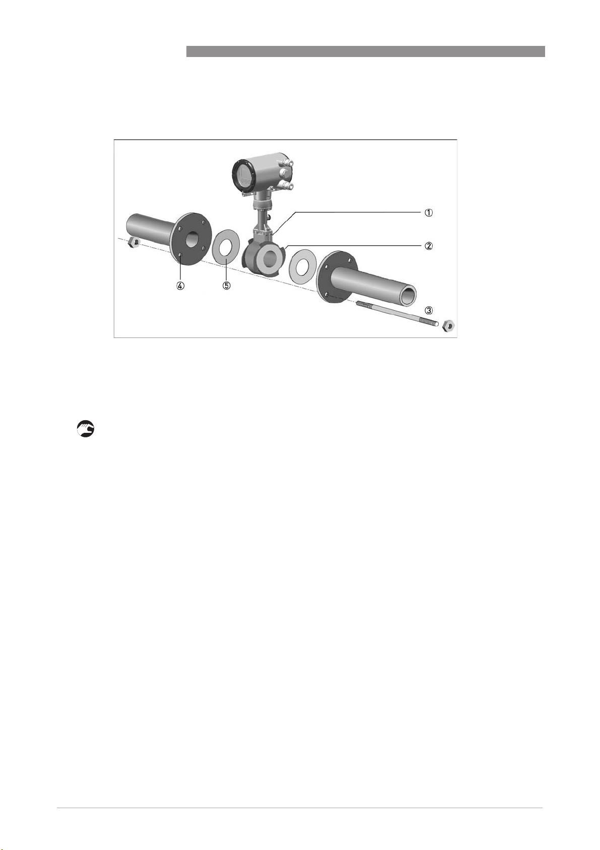
Figure 3-13: Installing devices in flange design
1 Sealing
2 Bolts with fastening nuts
• Use bolts and fastening nuts 2 to attach the measuring device to one side of the flange.
• While doing so, insert the gaskets 1 between flow sensor and flange and align them.
• Check that the gasket is concentric and that it is not protruding into the pipe cross-section.
• Install the gasket, bolts and fastening nuts on the other side of the flange.
• Align the measuring device and the gaskets so they are concentric.
• Now tighten all nuts bit by bit alternately across the diagonal.
www.krohne.com08/2016 - 4003930803 - MA OPTISWIRL 4200 R03 en
31
Page 32

3
INSTALLATION
3.8.4 Mounting the field housing, remote version
INFORMATION!
Assembly materials and tools are not part of the delivery. Use the assembly materials and tools
in compliance with the applicable occupational health and safety directives.
Pipe mounting
Figure 3-14: Pipe mounting of the field housing
OPTISWIRL 4200
1 Fix the signal converter to the pipe.
2 Fasten the signal converter using standard U-bolts and washers.
3 Tighten the nuts.
Wall mounting
Figure 3-15: Wall mounting of the field housing
1 Prepare the holes with the aid of the mounting plate.
2 Use the mounting material and tools in compliance with the applicable occupational health
and safety directives.
3 Fasten the housing securely to the wall.
32
INFORMATION!
Signal converters with a wall mounting rack have to be mounted with screws (Ø8 mm / 0.3") or
with U-brackets (Ø8 mm / 0.3") in case of pole installation. In case of mounting directly to the
wall, a mounting system with a minimum load force of 0.1 kN (for example FISCHER type UX10)
suitable for the background has to be applied.
www.krohne.com 08/2016 - 4003930803 - MA OPTISWIRL 4200 R03 en
Page 33

OPTISWIRL 4200
3.9 Heat insulation
CAUTION!
For applications with medium temperatures above +160
in accordance to the insulation guideline is suggested. Avoid higher electronic temperatures
°
than +80
The area above the signal converter support must not be heat-insulated.
The heat insulation 3 may only extend to the maximum height 1 shown below.
C / +176°F.
INSTALLATION
°
C / +320°F an insulation of the pipeline
3
Figure 3-16: Installation heat insulation
1 Max. height of the insulation up to the marking on the neck of the flow sensor
2 Max. thickness of the insulation up to the bend of the pressure pipe
3 Insulation
CAUTION!
The heat insulation 3 may only extend as far as the bend of the pressure sensing line 2.
www.krohne.com08/2016 - 4003930803 - MA OPTISWIRL 4200 R03 en
33
Page 34

3
INSTALLATION
3.10 Turning the connection housing
DANGER!
All work on the device electronics may only be carried out by appropriately trained personnel.
The regional occupational health and safety directives must always be observed.
OPTISWIRL 4200
Figure 3-17: Turning the connection housing
1 M4 Allen screw on connection housing
• Loosen the M4 Allen screw 1 on the side of the connection housing.
• Rotate the connection housing to the desired position (0...<360°).
• Tighten the M4 Allen screw 1 again.
34
www.krohne.com 08/2016 - 4003930803 - MA OPTISWIRL 4200 R03 en
Page 35

OPTISWIRL 4200
3.11 Turning the display
DANGER!
All work on the device electronics may only be carried out by appropriately trained personnel.
The regional occupational health and safety directives must always be observed.
INFORMATION!
If the measuring device is installed in a vertical pipe, you will have to turn the display by 90
installed below a pipe, turn 180
INFORMATION!
The display can be turned in increments of 90
INSTALLATION
°
.
°
to four positions.
°
3
; if
Figure 3-18: Turning the display
Turn the display as follows:
• Disconnect the power supply from the measuring device.
• Unscrew the housing cover with the key 1.
• Please use the handle to pull out the display module.
• First put the handle on side "a" and then on side "b" of the display, and then pull out the
display 2 carefully. Turn it into the favoured position 3.
• Disconnect the display from the handle first on side "a" and then on side "b".
• Press the display onto the spacer pins 4, until it clicks.
• Turn the cover with gasket 5 back onto the housing and tighten it by hand.
INFORMATION!
Before closing the housing cover refer to Maintaining the O-rings on page 93
.
www.krohne.com08/2016 - 4003930803 - MA OPTISWIRL 4200 R03 en
35
Page 36

4
ELECTRICAL CONNECTIONS
4.1 Safety instructions
DANGER!
All work on the electrical connections may only be carried out with the power disconnected. Take
note of the voltage data on the nameplate (for details refer to Nameplate on page 21
DANGER!
Observe the national regulations for electrical installations!
DANGER!
For devices used in hazardous areas, additional safety notes apply; please refer to the Ex
documentation.
WARNING!
Observe without fail the local occupational health and safety regulations. Any work done on the
electrical components of the measuring device may only be carried out by properly trained
specialists.
OPTISWIRL 4200
).
INFORMATION!
Check the device nameplate to ensure that the device is delivered according to your order. Check
for the correct supply voltage printed on the nameplate.
36
www.krohne.com 08/2016 - 4003930803 - MA OPTISWIRL 4200 R03 en
Page 37

OPTISWIRL 4200
4.2 Connecting the signal converter
DANGER!
All work on the electrical connections may only be carried out with the power disconnected. Take
note of the voltage data on the nameplate!
INFORMATION!
When using the binary output M1...M4 as pulse output and frequencies above 100 Hz, shielded
cables are to be used in order to reduce effects from electrical interferences (EMC).
ELECTRICAL CONNECTIONS
4
Figure 4-1: Connecting the signal converter
1 Open the housing cover of the electrical terminal compartment using the key
2 Signal converter supply and 4...20 mA loop
3 4...20 mA current input, - external transmitter, optional
4 Terminal M1 binary (high current)
5 Terminal M3 binary (NAMUR)
6 Terminal M2/4 binary, common minus connection
7 Ground terminal in housing
8 Ground terminal on connection piece between flow sensor and signal converter
INFORMATION!
Both grounding terminals 7 and 8 are equally effective from a technical point of view.
Steps for connecting the signal converter:
• Unscrew the housing cover 1 of the electrical terminal compartment.
• Feed the connection cable through the cable entry in the housing.
• Connect the cable according to the terminal diagrams below.
• Connect the grounding to the terminal 7. Alternatively use the ground terminal 8 on the
connection piece between the flow sensor and the signal converter.
• Tighten the cable glands.
• Turn the housing cover and gasket back onto the housing and tighten it by hand.
INFORMATION!
Ensure that the housing gasket is properly fitted, clean and undamaged.
Before closing the housing cover refer to Maintaining the O-rings on page 93
.
www.krohne.com08/2016 - 4003930803 - MA OPTISWIRL 4200 R03 en
37
Page 38

4
ELECTRICAL CONNECTIONS
4.3 Electrical connections
The signal converter is a 2-wire device with 4...20 mA as output signal. All other inputs and
outputs are passive and always require an additional power supply.
4.3.1 Power supply
All versions are intended for connection to limited-energy circuits of max. 36 VDC / 4 A.
INFORMATION!
The supply voltage has to be between 12 VDC and 36 VDC (12...30 VDC for Ex). This is based on
the total resistance of the measuring loop. To calculate this, the resistance of each component in
the measuring loop (not including the device) must be added up.
The required supply voltage can be calculated using the formula below:
U
= RL * 22 mA + 12 V
ext.
with
U
= the minimum supply voltage
ext.
= the total measuring loop resistance
R
L
OPTISWIRL 4200
INFORMATION!
The power supply has to be able to supply a minimum of 22 mA.
4.3.2 Current output
Figure 4-2: Electrical connection current output
1 Power supply for current output
2 Optional display unit (R
3 Load for HART
Connect current loop 4..20 mA to terminals C1+ and C2-.
When connection cables are long, a shielded or twisted cable may be necessary. The cable shield
may only be grounded at one place (e.g. on the power supply unit).
®
≥ 250 Ω
)
L
38
www.krohne.com 08/2016 - 4003930803 - MA OPTISWIRL 4200 R03 en
Page 39

OPTISWIRL 4200
4.3.3 Current input
An external transmitter, e.g. temperature or pressure transmitter, can be connected to
terminals I1+ and I2-. The 4...20 mA current signal is converted to the corresponding
temperature or pressure value in the signal converter.
ELECTRICAL CONNECTIONS
4
Figure 4-3: Electrical connection current input
1 Power supply for the signal converter
2 Current input of an external temperature or pressure transmitter
The current input can be configured in menu C1.5. Depending on the configuration of the current
input, the sources for temperature and/or pressure value have to be adjusted in menu C1.6 or
C1.7.
4.3.4 Binary output
Unless otherwise ordered, the binary output is inactive by default and must thus be activated and
configured as limit switch output, pulse output, frequency output or status output in menu C2.2
prior to first use. The binary output is electrically separated from the current output and must be
supplied with power separately.
www.krohne.com08/2016 - 4003930803 - MA OPTISWIRL 4200 R03 en
39
Page 40

4
ELECTRICAL CONNECTIONS
4.3.5 Limit switch output
Figure 4-4: Connection binary output
1 Power supply U
2 Isolated switching amplifier
ext.
OPTISWIRL 4200
INFORMATION!
Binary output Mx can only be operated if the loop supply 4...20 mA is applied to the terminals C1+
and C2-. The binary output is inactive by default and must thus be activated in menu C2.2 prior to
first use.
Connection binary output
Connection binary output
Connection binary outputConnection binary output
In accordance with the desired signal transmission, select one of the following connection types
for binary output M:
• M2/4 and M3 - NAMUR (DC interface in accordance with EN 60947-5-6)
• M2/4 and M1 - Transistor output (passive, open collector)
Terminal connection
Terminal M1 M3 M2/4
Connection NAMUR + (open collector,
Connection transistor output + (open collector,
I
max
< 100 mA)
Ri~1kΩ)
Common
Common
40
www.krohne.com 08/2016 - 4003930803 - MA OPTISWIRL 4200 R03 en
Page 41

OPTISWIRL 4200
Value range for NAMUR
Switching value reached < 1 mA > 3 mA
Switching value not reached > 3 mA < 1 mA
1 C2.2.6 Invert Signal On
2 C2.2.6 Invert Signal Off
Value range applies only when connected to a switching amplifier with the following reference
values:
- Open-circuit voltage U
- Internal resistance R
Value range for transistor output
=8.2VDC
0
=1kΩ
i
ELECTRICAL CONNECTIONS
NC contact 1 NO contact 2
4
via load R
U
L
L
0...2 V 0...2 mA 16...30 V 20...100 mA
I
L
U
H
I
H
To ensure the value ranges, a load RL between 250 Ω and 1 kΩ is recommended for the passive
transistor output with a nominal voltage of 24 VDC. If other loads are used, caution is advised as
the range of values of the signal voltages then no longer corresponds to the range of values for
the inputs of process control systems and controls (DIN IEC 946).
CAUTION!
The upper limit of the signal current must not be exceeded as this may damage the transistor
output.
For selection of measurement variable and adjustable data of the limit switch refer to chapter
"Menu description C - Setup", menu "C2.2.5 Limit Switch" and appropriate submenus.
www.krohne.com08/2016 - 4003930803 - MA OPTISWIRL 4200 R03 en
41
Page 42

4
ELECTRICAL CONNECTIONS
4.3.6 Pulse output / Frequency output
The maximum frequency of both pulse output and frequency output is 1000 Hz.
Figure 4-5: Electrical connection pulse output
1 Signal converter power supply
2 Pulse output power supply
3 Pulse counter or frequency meter
OPTISWIRL 4200
The connection is made between terminal M2/4 Common (-) and M1 for Hi Current (+) or M3
NAMUR (+). Only one of the two connections M1 or M3 can be selected in menu C2.2. The output
is selected as pulse or frequency output in menu C2.2. The output is a passive "open collector"
output which is electrically separated from the current interface and the flow sensor. It requires
its own power supply 2. The total resistance must be adapted so that the total current I
tot
does
not exceed 120 mA.
Figure 4-6: Pulse output signal definition
1 T
max
2 Closed
3 Open
4 Pulse width ≥ 0.5 ms
For selection of measurement variable and adjustable data of the pulse or frequency output
refer to chapter "Menu description C - Setup", menu "C2.2.2 Pulse Output" or menu "C2.2.3
Frequency Output" and appropriate submenus.
42
INFORMATION!
Make sure the pulse width is in line with the pulse rate.
www.krohne.com 08/2016 - 4003930803 - MA OPTISWIRL 4200 R03 en
Page 43

OPTISWIRL 4200
4.3.7 Status output
The + pole of the high current output is on the M1 terminal connection. The + pole of the NAMUR
output is on the M3 connection terminal. Terminal M2/4 is the common - pole of the status
output.
High current terminal M1...M2/4
High current terminal M1...M2/4
High current terminal M1...M2/4High current terminal M1...M2/4
Open Maximum voltage U
Closed Maximum current I
NAMUR terminal M3...M2/4
NAMUR terminal M3...M2/4
NAMUR terminal M3...M2/4NAMUR terminal M3...M2/4
Ri = 900 Ω U
= 36 VDC
max
For selection of status function and adjustable data of the status output refer to chapter "Menu
description C - Setup", menu "C2.2.4 Status Output" and appropriate submenus.
4.4 Connection of remote version
ELECTRICAL CONNECTIONS
= 36 VDC Closed current IR < 1 mA
max
= 100 mA Voltage U < 2 VDC
max
4
The connection terminals in the connection box of the flow sensor and the wall bracket are
identical in construction.
Connection cable strand colour
Terminals Strand colour
rd red
bu blue
bk black
gr grey
ye yellow
gn green
gnye Shielding
www.krohne.com08/2016 - 4003930803 - MA OPTISWIRL 4200 R03 en
43
Page 44

4
ELECTRICAL CONNECTIONS
OPTISWIRL 4200
Figure 4-7: Connection of remote version
1 Terminal connection of flow sensor
2 Terminal connection of signal converter
3 Terminal end pair shielding of flow sensor
4 Filler wire pair shielding (protected with heat shrink tubing)
5 Fork clamp pair shielding on signal converter side
6 Heat shrink tubing
The maximum cable length is 50 m / 164 ft.
The cable can be shortened easily. All wires must be connected afterwards.
CAUTION!
Please ensure that the shielding 4 has been properly connected to both terminals 3 and 5. The
exterior shielding of the cable must not be connected to any terminal.
44
www.krohne.com 08/2016 - 4003930803 - MA OPTISWIRL 4200 R03 en
Page 45

OPTISWIRL 4200
4.5 Grounding connections
The grounding can be done either by connecting the PE (Protective Earth) terminal in the
housing or the PE terminal on the connection piece between flow sensor and signal converter.
Both of these electrical connections are equally effective from a technical point of view.
ELECTRICAL CONNECTIONS
4
Figure 4-8: Ground connection compact version
1 Electrical grounding connection on connection piece between flow sensor and signal converter.
2 Electrical grounding terminal in the housing
CAUTION!
The measuring device has to be grounded properly to achieve accurate measurement. The
grounding wire may not transfer any interference voltage.
Do not use this grounding cable to ground any other electrical devices.
Figure 4-9: Ground connection remote version
1 Electrical grounding connection on flow sensor
2 Electrical grounding connection on signal converter housing
INFORMATION!
In the remote version, the flow sensor as well as the signal converter must be grounded.
www.krohne.com08/2016 - 4003930803 - MA OPTISWIRL 4200 R03 en
45
Page 46

4
ELECTRICAL CONNECTIONS
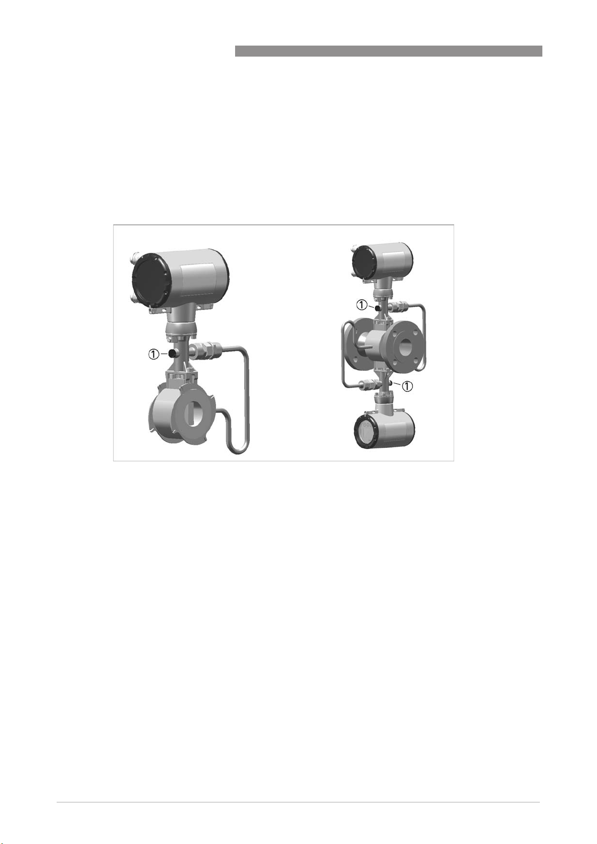
4.6 Ingress protection
The signal converter electronics housing meets the requirements for IP66/67 in accordance with
EN 60529 both for the compact and for the remote version.
CAUTION!
After all servicing and maintenance work on the measuring device, the specified ingress
protection category must be ensured again.
OPTISWIRL 4200
Figure 4-10: Cable feedthrough
Therefore it is essential to observe the following points:
• Use only original gaskets. They must be clean and free of any damage. Defective gaskets must
be replaced.
• The electrical cables used must be undamaged and must comply with regulations.
• The cables must be laid with a loop 1 upstream of the measuring device to prevent water
from getting into the housing.
• The cable feedthroughs 2 must be tightened. Note that the clamping range of the cable
feedthrough corresponds to the outer diameter of the cable.
• Align the measuring device so that the cable feedthrough is never facing up 3.
• Close any unused cable feedthroughs using blind plugs 4 suitable for the protection category.
• Do not remove the required cable bushing from the cable feedthrough.
46
www.krohne.com 08/2016 - 4003930803 - MA OPTISWIRL 4200 R03 en
Page 47

OPTISWIRL 4200
5.1 Start-up screen
INFORMATION!
After connection to power supply the device carries out a self-test. After 10 seconds the
following start-up screen appears:
START-UP
5
Figure 5-1: Start-up screen
After finishing of the self-test the device switches to the measuring mode. Here, all of the
parameters preset for the customer are analysed and checked for plausibility, and the currently
measured value is displayed.
5.2 Operation
INFORMATION!
The measuring device is largely maintenance-free.
Observe the application limits in respect of temperature and medium.
www.krohne.com08/2016 - 4003930803 - MA OPTISWIRL 4200 R03 en
47
Page 48

6
OPERATION
6.1 Display and operating elements
In case of an open front cover, the device is operated by using mechanical keys; in the case of a
closed cover, a bar magnet 1 is used.
Figure 6-1: Pen with bar magnet
CAUTION!
The switching point of the magnetic sensors is directly under the glass panel above the
appropriate symbol. Touch the symbol only vertically and from the front. Touching it from the
side may cause a malfunction.
OPTISWIRL 4200
48
Figure 6-2: Display and operating elements
1 Display
2 Mechanical keys and bar magnet
3 Bargraph indication
4 1st measured variable in large representation
5 Indicates when a key has been pressed
6 Tag number (only shown if entered previously by the operator)
7 Indicates a possible status message in the status list
www.krohne.com 08/2016 - 4003930803 - MA OPTISWIRL 4200 R03 en
Page 49

OPTISWIRL 4200
The mechanical keys and keys for the bar magnet have the same functionality. In this
documentation the keys are represented as symbols to describe the operating functions:
Table 6-1: Description of keys
OPERATION
Mechanical and bar magnet Symbol
→
^
↓
↑
6
Figure 6-3: Displays in measuring mode (examples for 2 or 3 measured values)
x, y and z denote the units of the measured values displayed
6.1.1 Display for selection of submenu and functions, 3 lines
Figure 6-4: Display for selection of submenu and functions, 3 lines
1 Indicates a possible status message in the status list
2 Menu, submenu or function name
3 Number relating to 6
4 Indicates position within menu, submenu or function list
5 Next menu(s), submenu or function
(_ _ _ signals in this line the end of the list)
6 Current menu(s), submenu or function
7 Previous menu(s), submenu or function
(_ _ _ signals in this line the beginning of the list)
www.krohne.com08/2016 - 4003930803 - MA OPTISWIRL 4200 R03 en
49
Page 50

6
OPERATION
6.1.2 Display when setting parameters, 4 lines
Figure 6-5: Display when setting parameters, 4 lines
1 Current menu(s), submenu or function
2 Number relating to 7
3 Denotes factory setting
4 Denotes permissible value range
5 Permissible value range for numeric values
6 Currently set value, unit or function (when selected, appears with white text, blue background)
This is where the data is changed.
7 Current parameter
8 Factory setting of parameter
OPTISWIRL 4200
6.1.3 Display when previewing parameters, 4 lines
Figure 6-6: Display when previewing parameters, 4 lines
1 Current menu(s), submenu or function
2 Number relating to 6
3 Denotes a changed parameter (simple check of changed data when browsing through lists)
4 Next parameter
5 Currently set data from 6
6 Current parameter (for selection press key >; then see previous chapter)
7 Factory setting of parameter
50
www.krohne.com 08/2016 - 4003930803 - MA OPTISWIRL 4200 R03 en
Page 51

OPTISWIRL 4200
6.2 Basic principles of operation
6.2.1 Functional description of the keys
INFORMATION!
•
It is recommended to activate the push buttons perpendicular to the front. Touching them
from the side can cause incorrect operation.
•
The mechanical keys and keys for the bar magnet have the same functionality.
→ Switch from measuring mode to menu mode
Switch to one menu level lower
Open menu item and activate change mode
In change mode:
In change mode: Move the input cursor one position to the right; after the last digit
In change mode:In change mode:
the input cursor jumps back to the beginning.
↑ or ↓ Change between the menu items within a menu level
In measuring mode:
In measuring mode: Switch between 1. measurement page, 2. measurement page
In measuring mode:In measuring mode:
and status message.
In change mode:
In change mode: Changing parameters and settings; running through the available
In change mode:In change mode:
characters; shifting the decimal point to the right or left.
^ Confirm settings and changes
Return to measuring mode
Table 6-2: Description of the operating keys
OPERATION
6
6.2.2 Switch from measuring mode to menu mode
Measuring mode
Measuring mode Operation
Measuring modeMeasuring mode
156.3 kg/h → > Quick Setup
Operation Menu mode
OperationOperation
Use the ^ button to exit menu mode and return to measuring mode.
6.2.3 Change the settings in the menu
Press the → button to enter the menu.
Use the ^ button to exit menu mode and return to measuring mode.
• Use the ^ and ↑ or ↓ keys to navigate in the menu.
The current values or settings are displayed.
Save the new value or setting using the ^ key.
• Some menu items contain several setting options. They are displayed in sequence by pressing
the ^ key.
• Press the ^ button to save the settings, or to reject them.
• Before returning to measuring mode, you are prompted "Save Configuration?" which you need
to accept with "Yes".
Switch between "Yes", "Back" and "No" by pressing the ↑ or ↓ keys.
Menu mode
Menu modeMenu mode
www.krohne.com08/2016 - 4003930803 - MA OPTISWIRL 4200 R03 en
51
Page 52

6
OPERATION
OPTISWIRL 4200
Save Configuration?
Yes
Save Configuration?
No
Save Configuration?
Back
^^^^ Changes are accepted.
An update is carried out and the display returns to measuring mode.
^^^^ Changes are discarded.
The display returns to measuring mode.
^^^^ Returns to menu mode
Example: Changing the default parameter from m3/h to l/h
Procedure Display Procedure Display
1.25
3
/h
m
2x → A
8x ↓ A9
2x → Volume Flow
Quick Setup
Units
3
/h
m
6.2.4 Character selection in change mode
Depending on the menu function, the following characters are available:
Numbers
8x ↑ Volume Flow
L/h
4x ^ Save Configuration?
Yes
1x ^ 1250
L/h
0 1 2 3 4 5 6 7 8 9
Lower case letters
a b c d e f g h i j
k l m n o p q r s t
u v w x y z
Upper case letters
A B C D E F G H I J
K L M N O P Q R S T
U V W X Y Z
Special characters
2 3
_ - / ....
52
www.krohne.com 08/2016 - 4003930803 - MA OPTISWIRL 4200 R03 en
Page 53

OPTISWIRL 4200
6.2.5 Units, figures and factors
Numerical values and factors are displayed in a 8 digit format. Numerical values are either
displayed in floating point format (12345678) or are expressed in exponential format (12.345e06).
Exponents are used in following steps: 03 / 06 / 09 or -03 / -06 / -09 etc. The conversion factor of
the totalizer and the pulse output, however, is expressed in whole numbers.
Basic units
Flow type Basic units Menu
OPERATION
6
Volume flow
Norm. volume flow
Mass flow kg/h A9 and/or C6.5
User defined units can be entered in menu "A9 or C6.5 Units". The unit (text) as well as the
conversion factor (number) and offset can be entered here. The conversion factor must always
be entered based on the basic unit.
Totalizer
The basic units for the totalizer are mmmm
Volume flow, norm. volume flow and mass flow can be selected in menu "C4.1 Flow Totalizer".
If counting is to be done in another flow unit, the unit must be changed in menu "C6.5 Units".
6.2.6 Security and permissions
Access levels
Access levels
Access levelsAccess levels
The vortex flowmeter features a multi-level security concept, which helps to prevent accidental
or unauthorised configuration changes.
To gain a specific access level you need to log into the device by entering a four digit hexadecimal
password associated with that access level (refer to menu "C6.2 Security"). You are able to
change the passwords of "Operator" and "Expert" access levels if that particular level has been
reached.
m3/h
Nm3/h
3333
for volume, Nm3 for standard volume and kg for mass.
A9 and/or C6.5
A9 and/or C6.5
The "User" access level does not have a specific password – if you enter any password not
assigned to a level, e.g. "0000" (which is an invalid password), you will fall back to "User" access
level.
www.krohne.com08/2016 - 4003930803 - MA OPTISWIRL 4200 R03 en
53
Page 54

6
OPERATION
The table below lists the access levels, their default passwords and associated permissions.
Access level
Access level Default password
Access levelAccess level
User 0000
Operator 0009
Expert 0058
INFORMATION!
When a particular access level has been enabled, please pay close attention to a "lock" symbol
which might be present at the right side of a menu entry. This lock symbol indicates that your
current access level allows you to read but not write this entry.
Default password Permissions
Default passwordDefault password
(any unassigned
password)
Permissions
PermissionsPermissions
•
View device information
•
Configure the display (C5), including changing the display
language and the content of the measurement pages
•
All rights of "User" access level
•
Configure binary output (C2.2)
•
Configure all HART® communication options (C3) with the
exception of "C3.1.1 Current Loop Mode"
•
Change "Operator" password (C6.2.2) – note that the new
password must have three leading zeroes ("000")
•
Activate a different meter type
•
All configuration rights, especially process setup (C1) and
current output (C2.1)
•
Change "Expert" password (C6.2.2) – note that the new
password must have two leading zeroes ("00")
OPTISWIRL 4200
INFORMATION!
–
When entering the four digit password please be sure to type in all leading zeroes
i.e. enter the
default "Operator" password as "0009" and not only "9" by skipping the remaining digits.
INFORMATION!
After a cold start of the device the user role will always be reset to "User".
Reset passwords
Reset passwords
Reset passwordsReset passwords
In case the user has changed particular passwords from their default settings and is not able to
log in anymore, there is a "Reset Passwords" command available in the C6.2.3 submenu.
However to prevent unauthorised use this command itself is protected by a non-changeable
unique password available by contacting the manufacturer.
54
www.krohne.com 08/2016 - 4003930803 - MA OPTISWIRL 4200 R03 en
Page 55

OPTISWIRL 4200
6.3 Overview of the most important functions and units
INFORMATION!
A complete list of all functions and short descriptions is provided in the next section. All default
parameters and settings are adapted for the customer.
Menu structure
• "A Quick Setup": Quick check and setup of the signal converter, including application
assistants
• "B Test": Simulation functions and display of the actual measurement values for all variables
• "C Setup": Complete setup possibilities
Frequently used functions
Menu Explanation
A1 Language or C5.1 Language Select the menu language (for details refer to following chapter)
B1.2 Current Output Check the current output
B1.3.1 Pulse Output Check the pulse output
B1.3.2 Frequency Output Check the frequency output
B1.3.3 Status/Limit Output Check the status output
C1.8 Time Constant Time constant, damping value
C2.1.2 0% Range Minimum flow rate (current output)
The set value represents the 4 mA value of the current output.
Usually 0% of flow is set as 4 mA, but it is also possible to assign
higher flow values to 4 mA.
C2.1.3 100% Range Maximum flow rate (current output)
The set value represents the 20 mA value of the current output.
Usually 100% of flow is set as 20 mA, but it is also possible to
assign lower flow values to 20 mA.
Table 6-3: Most important functions
OPERATION
6
6.4 Menu languages
Language selection
English German French
In preparation:
In preparation:
In preparation:In preparation:
Italian Portuguese Dutch Spanish Swedish
Russian Norwegian Finnish Slovenian Czech
Hungarian Slovak Albanian Bulgarian Romanian
Moldavian Danish Polish Lithuanian Chinese
Estonian Latvian Turkish
Table 6-4: Menu languages
www.krohne.com08/2016 - 4003930803 - MA OPTISWIRL 4200 R03 en
55
Page 56

6
OPERATION
6.5 Gas options for gas measurement
Gases can be selected in menu "A8, C1.2 Medium" or "C1.3.1 Gas Mixture".
For fluid selection gas, wet gas or gas mixture the following gas selection is available:
Air Ammonia Argon i-Butane n-Butane
CO CO
Hydrogen Hydrogen
Oxygen i-Pentane n-Pentane Propane Xenon Custom
2
Sulfide
Gas mixtures can be defined as percentage shares of the above mentioned gases.
Default format for the shares is 0.00000 %.
To enter shares > 9.99999 % the point can be shifted rightwards by moving the cursor to the point
and then press the upwards button ↑.
Change between the digits by pressing the rightwards button →.
After reaching the last digit the cursor will jump again to the first digit.
Ethane Ethylene n-Hexane
Methane Neon Nitrogen
OPTISWIRL 4200
56
www.krohne.com 08/2016 - 4003930803 - MA OPTISWIRL 4200 R03 en
Page 57

OPTISWIRL 4200
6.6 Units
The following units can be selected and set in menu A9 and/or C6.5. Furthermore, for each
measurement customised units can be defined.
Units for volume flow
Units for volume flow
Units for volume flowUnits for volume flow
Liquids, steam, gases
m
ml ml ml ml
L L L L
ML ML - -
hl hl hl hl
ft
gal gal gal gal
kgal kgal kgal kgal
Mgal Mgal - -
ImpGal ImpGal ImpGal ImpGal
MImpGal MImpGal - -
bbl bbl bbl bbl
acft acft acft acft
fl.oz[Imp] fl.oz[Imp] fl.oz[Imp] fl. oz[Imp]
fl.oz[US] fl.oz[US] fl.oz[US] fl.oz[US]
Customised volume flow
Table 6-5: Flow measurements and their units
OPERATION
6
/d /h /min /s
3
3
3
m
3
ft
3
m
3
ft
3
m
3
ft
Units for norm./standard* volume flow
Units for norm./standard* volume flow
Units for norm./standard* volume flowUnits for norm./standard* volume flow
Liquids, steam, gases
/d /h /min /s
3
Nm
NL NL NL NL
3
Sm
SL SL SL SL
3
Sft
Customised norm./standard volume flow
Table 6-6: Flow measurements and their units
Nm
Sm
Sft
3
3
3
Nm
Sm
Sft
3
3
3
Nm
Sm
Sft
3
3
3
* The units Nx/x and Sx/x shall be considered as equivalent. They serve as an indication for a
normalised or standardised measuring variable and do not identify the underlying reference
system.
www.krohne.com08/2016 - 4003930803 - MA OPTISWIRL 4200 R03 en
57
Page 58

6
OPERATION
Units for mass flow
Units for mass flow
Units for mass flowUnits for mass flow
kg kg kg kg
- g g g
t t t -
lb lb lb lb
Customised mass flow
Table 6-7: Flow measurements and their units
Totalizer units
Totalizer units
Totalizer unitsTotalizer units
Volume Norm./standard* volume Mass
3
m
L SL kg
hl
3
in
3
ft
gal
ImpGal
bbl
Customised volume
Table 6-8: Totalizer units
OPTISWIRL 4200
/d /h /min /s
3
Nm
3
SM
3
Sft
NL T
g
oz
lb
* The units Nx and Sx shall be considered as equivalent. They serve as an indication for a
normalised or standardised measuring variable and do not identify the underlying reference
system.
58
www.krohne.com 08/2016 - 4003930803 - MA OPTISWIRL 4200 R03 en
Page 59

OPTISWIRL 4200
Units additional measurements
Units additional measurements
Units additional measurementsUnits additional measurements
Temperature Pressure Power Energy Density
°C mbar W J
°F bar kW kJ kg/L
K atm kJ/h MJ
°Rank
Customised
temperature
Table 6-9: Units additional measurements
OPERATION
3
kg/m
3
g/cm
2
kg/m
2
kg/cm
2
g/cm
torr Btu/h Customised
psi Mbtu/s
psi (abs) Mbtu/h Customised
2
b/ft
MPa Customised power
kPa
Pa
Customised
pressure
MJ/s kW*h g/L
MJ/h Mcal g/ml
Mcal/h BTU lb/gal
energy
Mbtu/d
lb/ft
lb/in
density
3
3
6
The pressure unit psi (abs) refers to a reference point of 0 bara / 0 psia.
All other pressure units are gauge pressure units and refer to a reference pressure of
1.013 bara / 14.7 psia (acc. to DIN 1343).
www.krohne.com08/2016 - 4003930803 - MA OPTISWIRL 4200 R03 en
59
Page 60

6
OPERATION
6.7 Menu structure
6.7.1 Menu overview "A Quick Setup"
Meas. Menu A Submenus
> ^ ↓ ↑ > ^ ↓ ↑ > ^ ↓ ↑
A Quick Setup A1 Language
A2 Contrast
A3 Login
A4 Tag
A5 Long Tag
A6 Message View
A7 Fluid
A8 Medium
A9 Units A9.1 Volume Flow A9.2 Cst. Vol. Flow
A9.3 Norm. Vol. Flow A9.4 Cst. N.Vol.Flow
A9.5 Mass Flow A9.6 Cst. Mass Flow
A9.7 Power A9.8 Cst. Power
A9.9 Volume A9.10 Cst. Volume
A9.11 Norm. Volume A9.12 Cst. Norm. Volume
A9.13 Mass A9.14 Cst. Mass
A9.15 Energy A9.16 Cst. Energy
A9.17 Pressure A9.18 Cst. Pressure
A9.19 Temperature A9.20 Cst. Temp.
A9.21 Density A9.22 Cst. Density
A10 Meter Type
A11 Application
Assistant
A12 Cluster
Checks
A11.1 Liquids
A11.2 Saturated Steam
A11.3 Superheated Steam
A11.4 Heat Measurement
A11.5 Gas
A11.6 FAD
Cluster 1...12
OPTISWIRL 4200
60
www.krohne.com 08/2016 - 4003930803 - MA OPTISWIRL 4200 R03 en
Page 61

OPTISWIRL 4200
OPERATION
6.7.2 Menu overview "B Test"
Meas. Menu B Submenus
> ^ ↓ ↑ > ^ ↓ ↑ > ^ ↓ ↑ > ^ ↓ ↑ >
B Test B1 Simulation B1.1 Set Value B1.1.1 Volume Flow
B1.1.2 Norm. Volume Flow
B1.1.3 Mass Flow
B1.1.4 Gross Power
B1.1.5 Net Power
B1.1.6 FAD
B1.1.7 Volume
B1.1.8 Norm. Volume
B1.1.9 Mass
B1.1.10 Gross Energy
B1.1.11 Net Energy
B1.1.12 Density
B1.1.13 Temperature1
B1.1.14 Temperature2
B1.1.15 Pressure
B1.1.16 Vortex Frequency
B1.1.17 Velocity
B1.1.18 Specific Enthalpy
B1.1.19 Specific Heat Cap.
B1.1.20 Reynolds Number
B1.2 Current Output
B1.3 Binary Output B1.3.1 Pulse Output
B1.3.2 Frequency Output
B1.3.3 Status/Limit Output
B Test B2 Actual
Values
B2.1 Operating Time
B2.2 Volume Flow
B2.3 Norm. Volume Flow
B2.4 Mass Flow
B2.5 Gross Power
B2.6 Net Power
B2.7 FAD
B2.8 Volume
B2.9 Norm. Volume
B2.10 Mass
B2.11 Gross Energy
B2.12 Net Energy
B2.13 Density
B2.14 Temperature1
B2.15 Temperature2
6
www.krohne.com08/2016 - 4003930803 - MA OPTISWIRL 4200 R03 en
61
Page 62

6
OPERATION
Meas. Menu B Submenus
> ^ ↓ ↑ > ^ ↓ ↑ > ^ ↓ ↑ > ^ ↓ ↑ >
OPTISWIRL 4200
B Test B2 Actual
Values
B2.16 Pressure
B2.17 Vortex Frequency
B2.18 Velocity
B2.19 Specific Enthalpy
B2.20 Specific Heat Cap.
B2.21 Reynolds Number
6.7.3 Menu overview "C Setup"
Meas. Menu C Submenus
> ^ ↓ ↑ > ^ ↓ ↑ > ^ ↓ ↑ > ^ ↓ ↑ >
C Setup C1 Process C1.1 Fluid
C1.2 Medium
C1.3 Gas C1.3.1 Gas Mixture
C1.3.2 Relative Humidity
C1.3.3 Inlet Temperature
C1.3.4 Atm. Pressure
C1.3.5 Filter Pressure Drop
C1.3.6 Inlet Rel. Humidity
C1.3.7 Outlet Rel. Humidity
C1.3.8 Compressor RPM
C1.3.9 Rated Compr. RPM
C1.4 Saturated
Steam
C1.5 Current Input C1.5.1 Function
C1.6 Temp. Sensor C1.6.1 Temp. Source1
C1.7 Pressure
Sensor
C1.8 Time Constant
C1.9 Low Flow Cutoff
C1.10 Operating
Values
C1.4.1 Dry Factor
C1.5.2 Current Input Meas.
C1.5.3 0% Range / 4mA
C1.5.4 100% Range / 20mA
C1.6.2 Temp. Source2
C1.7.1 Pressure Source
C1.10.1 Oper. Temperature
C1.10.2 Oper. Pressure
C1.10.3 Oper. Density
C1.10.4 Min/Max Oper. Dens.
62
www.krohne.com 08/2016 - 4003930803 - MA OPTISWIRL 4200 R03 en
Page 63

OPTISWIRL 4200
OPERATION
Meas. Menu C Submenus
> ^ ↓ ↑ > ^ ↓ ↑ > ^ ↓ ↑ > ^ ↓ ↑ >
C Setup C2 Output C1.11 Normal Values C1.11.1 Norm. Temperature
C1.11.2 Norm. Pressure
C1.11.3 Norm. Density
C2.1 Current Output C2.1.1 Current Out. Meas.
C2.1.2 0% Range
C2.1.3 100% Range
C2.1.4 Lower Ext. Range
C2.1.5 Upper Ext. Range
C2.1.6 Error Function
C2.1.7 Low Error Current
C2.1.8 High Error Current
C2.1.9 Trimming
C2.2 Binary Output C2.2.1 Function
C2.2.2 Pulse Output
C2.2.3 Frequency Output
C2.2.4 Status Output
C2.2.5 Limit Switch
C2.2.6 Invert Signal
C3
Communication
C4 Totalizer C4.1 Flow Totalizer C4.1.1 Measurement
C3.1 HART C3.1.1 Current Loop Mode
C3.1.2 Identification
C3.1.3 Device Information
C3.1.4 HART Variables
C3.1.5 Catch DV Temp.
C3.1.6 Catch DV Pressure
C4.1.2 Preset Value
C4.1.3 Reset Totalizer?
C4.1.4 Set Start Value
C4.1.5 Start Totalizer?
C4.1.6 Stop Totalizer?
C4.1.7 Information
C4.2 Energy Totalizer C4.2.1 Measurement
C4.2.2 Preset Value
C4.2.3 Reset Totalizer?
C4.2.4 Set Start Value
C4.2.5 Start Totalizer?
C4.2.6 Stop Totalizer?
C4.2.7 Information
6
www.krohne.com08/2016 - 4003930803 - MA OPTISWIRL 4200 R03 en
63
Page 64

6
OPERATION
Meas. Menu C Submenus
> ^ ↓ ↑ > ^ ↓ ↑ > ^ ↓ ↑ > ^ ↓ ↑ >
C Setup C5 Display C5.1 Language
C5.2 Contrast
C5.3 1. Meas. Page C5.3.1 Function
C5.3.2 Measurement 1. Line
C5.3.3 0% Range
C5.3.4 100% Range
C5.3.5 Format 1. Line
C5.3.6 Measurement 2. Line
C5.3.7 Format 2. Line
C5.3.8 Measurement 3. Line
C5.3.9 Format 3. Line
C5.4 2. Meas. Page C5.4.1 Function
C5.4.2 Measurement 1. Line
C5.4.3 0% Range
C5.4.4 100% Range
C5.4.5 Format 1. Line
C5.4.6 Measurement 2. Line
C5.4.7 Format 2. Line
C5.4.8 Measurement 3. Line
C5.4.9 Format 3. Line
C6 Device C6.1 Information C6.1.1 Tag
C6.1.2 Long Tag
C6.1.3 Meter Type
C6.1.4 Serial Number
C6.1.5 Manufacturer ID
C6.1.6 Device Name
C6.1.7 V Number
C6.1.8 Electronic Revision
C6.1.9 Device Revision
C6.1.10 Software Revision
C6.1.11 Hardware Revision
C6.1.12 Electronic Serial No.
C6.1.13 CG Number
C6.1.14 Production Date
C6.1.15 Calibration Date
C6.2 Security C6.2.1 Login
C6.2.2 Change Password
C6.2.3 Reset Passwords
OPTISWIRL 4200
64
www.krohne.com 08/2016 - 4003930803 - MA OPTISWIRL 4200 R03 en
Page 65

OPTISWIRL 4200
OPERATION
6
Meas. Menu C Submenus
> ^ ↓ ↑ > ^ ↓ ↑ > ^ ↓ ↑ > ^ ↓ ↑ >
C Setup C6 Device C6.3 Extras C6.3.1 Meter Type
C6.3.2 Heat
C6.3.3 Heat & Dens. by Pres.
C6.3.4 Heat & Dens. & FAD
C6.4 Error C6.4.1 Message View
C6.5 Units C6.5.1 Volume Flow
C6.5.3 Norm. Vol. Flow
C6.5.5 Mass Flow
C6.5.7 Power
C6.5.9 Volume
C6.5.11 Norm. Volume
C6.5.13 Mass
C6.5.15 Energy
C6.5.17 Pressure
C6.5.19 Temperature
C6.5.21 Density
C6.6 Factory Default C6.6.1 Reset to Fact. Def.?
1 In all even numbered menus C6.5.2 to .22 Cst. Units (Custom Units) there is a submenu with the prompt for "Text", "Offset" and "Fac-
tor".
1
www.krohne.com08/2016 - 4003930803 - MA OPTISWIRL 4200 R03 en
65
Page 66

6
OPERATION
6.7.4 Menu description "A Quick Setup"
Function Setting / Description
OPTISWIRL 4200
A1 Language Available display languages: German, English and French
A2 Contrast Adjust contrast of local display (-10...+10; Standard = 0)
A3 Login Enter password: 0000 (to change password refer to menu C6.2.2)
A4 Tag Entry and display of measuring point identifier (8 digits).
A5 Long Tag Entry and display of long measuring point identifier (1...32 digits).
A6 Message View NAMUR messages (F, S, M, C, I)
A7 Fluid Select: Liquid / Steam / Gas / Wet Gas / Gas Mixture
A8 Medium If fluid is "Gas" or "Wet Gas" (for details refer to
A9 Units For further information refer to menu C6.5.
A10 Meter Type Standard:
A11 Application Assistant For details refer to next tables.
A12 Cluster Checks For further information refer to
22 more languages in preparation (for details refer to
Entry will be displayed in the header bar on the LC display (depending on letter size,
min. 11 digits can be displayed).
For further information refer to
86.
Depending on selected fluid, appropriate medium can be selected in A8
Status messages and diagnostic information
Menu languages
Gas options for gas measurement
page 56)
The following selection is available for fluid = "Steam":
Saturated Steam / Superheated Steam / Custom
The following selection is available for fluid = "Liquid":
Water / Custom
The following selection is available for fluid = "Wet Gas":
Here, a gas can be selected as a wet gas from all of the above mentioned gases.
For liquids, gases and steam; integrated temperature compensation for saturated
steam.
Heat:
For liquids, gases and steam; integrated temperature compensation for saturated
steam, gross/net heat measurement for saturated steam and water.
Heat & Dens. by Pres.:
Integrated density compensation for saturated steam, superheated steam and gas,
gross/net heat measurement for saturated steam, superheated steam and water.
Heat & Dens. & FAD:
Integrated density compensation for saturated steam, superheated steam and gas,
gross/net heat measurement for saturated steam, superheated steam and water, FAD
functionality.
A12 plausibility checks
on page 91.
on page 55)
on page
on
66
www.krohne.com 08/2016 - 4003930803 - MA OPTISWIRL 4200 R03 en
Page 67

OPTISWIRL 4200
A11 Application Assistant
The factory settings of the vortex flowmeter have been made in accordance with the order
specifications. Nonetheless it can be necessary to make additional settings for the use of some
functionalities. For an easy operation the device is equipped with an application assistant for
each type of application. The application assistant guides the operator through the configuration
of the flowmeter.
The application assistant starts with the definition of all basic units. Afterwards, the
functionality-specific parameters have to be set. Settings such as configurations of the outputs
or the totaliser functions, can require submenus. These can be entered by pressing the arrow
"→" key. In case they are not needed, the menu items can be skipped by pressing the enter "^"
key.
To perform the settings for the application assistant, the operator must be logged on the access
level "Expert". For further information refer to
To abort an application assistant sequence, press "→" and "↑" at the same time. Be sure to
select "Save Config.? No" when returning to measuring mode.
Security and permissions
OPERATION
on page 53.
6
Please select a suitable application assistant from the following options:
A11.1 Liquids Configuration for liquid applications, incl. the correspondent output and totalizer.
A11.2 Saturated Steam Configuration for saturated steam applications and density compensation by external
A11.3 Superheated Steam Configuration of superheated steam applications and definition of temperature and
A11.4 Heat Measurement Configuration of gross and net heat applications and definition of temperature and/or
A11.5 Gas Configuration of gas applications with optionally internal or external pressure and
A11.6 FAD Configuration of FAD (Free Air Delivery) applications for compressors.
or internal temperature transmitter.
pressure value sources.
pressure value sources.
temperature sources for the density compensation.
www.krohne.com08/2016 - 4003930803 - MA OPTISWIRL 4200 R03 en
67
Page 68

6
OPERATION
OPTISWIRL 4200
A11.1 Application Assistant - Liquid
Function Setting / Description
.1
.2 Units
.2.1 Volume Flow
.2.2 Mass Flow Select unit (default: according to order specification or kg/h).
.2.3 Volume
.2.4 Mass Select unit (default: according to order specification or kg).
.2.5 Temperature Select unit (default: according to order specification or °C).
.2.6 Pressure Select unit (default: according to order specification or bar).
.2.7 Density
.3 Process Process configuration.
.3.1 Fluid Select "Liquid".
.3.2 Medium Select "Water" or "Custom".
.3.3 Time Constant 0...100 s
.3.4 Low Flow Cutoff Enter low flow cutoff point in current volume flow unit.
.4 Operating Values Current process conditions in case they are not measured nor calculated.
.4.1 Oper. Temperature Input in selected unit.
.4.2 Oper. Pressure Input in selected unit.
.4.3 Oper. Density Input in selected unit.
.5 Current Output Current output configuration.
.5.1 Current Out. Meas. Select measurement variable for current output.
.5.2 0% Range The set value represents 4 mA at the current output. Usually 0% flow = 4 mA, but it is
.5.3 100% Range The set value represents 20 mA at the current output. Usually 100% flow = 20 mA, but it
.5.4 Error Function Low / Off / High / Hold
.5.5 Low Error Current 3.5...3.6 mA, available if "Error Function = Low"
.5.6 High Error Current 21...21.5 mA, available if "Error Function = High"
.6 Binary Output Optionally configure the binary output.
.6.1 Function Select the binary output function:
.6.2 Invert Signal On, Off
.7 Pulse Output This menu is available if "Binary Output Function = Pulse".
.8 Frequency Output This menu is available if "Binary Output Function = Frequency".
.9 Status Output This menu is available if "Binary Output Function = Status".
.10 Limit Switch This menu is available if "Binary Output Function = Limit Switch".
.11 Flow Totalizer Optionally configure the flow totalizer.
.12 Energy Totalizer This menu is available if a non-standard meter type has been configured (refer to "C6.3
.13 1. Meas. Page One Value / Two Values / Three Values / One Value & Bargraph / Two values &
.14 2. Meas. Page One Value / Two Values / Three Values / One Value & Bargraph / Two values &
Select unit (default: according to order specification or m3/h).
Select unit (default: according to order specification or m3).
Select unit (default: according to order specification or kg/m3).
also possible to define a higher flow value for 4 mA.
is also possible to define a lower flow value for 20 mA.
Limit Switch / Status / Frequency / Pulse / Off
Extras").
Bargraph
Bargraph
68
www.krohne.com 08/2016 - 4003930803 - MA OPTISWIRL 4200 R03 en
Page 69

OPTISWIRL 4200
A11.2 Application Assistant - Saturated Steam
Function Setting / Description
.1
.2 Units Same options as in A11.1.2.
.3 Process
.3.1 Fluid Select "Steam".
.3.2 Medium Select "Saturated Steam".
.3.3 Time Constant 0...100 s
.3.4 Low Flow Cutoff Enter low flow cutoff point in current volume flow unit.
.4 Current Input
.4.1 Function Select "On" if applicable.
.4.2 Current Input Meas. Select "Temperature External" if "Function = On".
.5.1 Temp. Source1 Internal / External / External HART / Not Available
.5.2 Temp. Source2 Internal / External / External HART / Not Available
Temperature source 1 and 2 must be different.
.6 Operating Values Same options as in A11.1.4.
.7 Current Output Same options as in A11.1.5.
.8 Binary Output Same options as in A11.1.6.
.9 Pulse Output Same options as in A11.1.7.
.10 Frequency Output Same options as in A11.1.8.
.11 Status Output Same options as in A11.1.9.
.12 Limit Switch Same options as in A11.1.10.
.13 Flow Totalizer Same options as in A11.1.11.
.14 Energy Totalizer Same options as in A11.1.12.
.15 1. Meas. Page Same options as in A11.1.13.
.16 2. Meas. Page Same options as in A11.1.14.
OPERATION
6
www.krohne.com08/2016 - 4003930803 - MA OPTISWIRL 4200 R03 en
69
Page 70

6
OPERATION
OPTISWIRL 4200
A11.3 Application Assistant - Superheated Steam
Function Setting / Description
This application assistant is available if meter type is set to "Heat & Dens. by Pres." or "Heat & Dens. & FAD" (refer to
"C6.3 Extras").
.1
.2 Units Same options as in A11.1.2.
.3 Process
.3.1 Fluid Select "Steam".
.3.2 Medium Select "Superheated Steam".
.3.3 Time Constant 0...100 s
.3.4 Low Flow Cutoff Enter low flow cutoff point in current volume flow unit.
.4 Current Input
.4.1 Function Select "On", if applicable.
.4.2 Current Input Meas. Select "Temperature External" or "Pressure External".
.5.1 Temp. Source1 Internal / External / External HART / Not Available
.5.2 Temp. Source2 Internal / External / External HART / Not Available
.6 Operating Values Same options as in A11.1.4.
.7 Current Output Same options as in A11.1.5.
.8 Binary Output Same options as in A11.1.6.
.9 Pulse Output Same options as in A11.1.7.
.10 Frequency Output Same options as in A11.1.8.
.11 Status Output Same options as in A11.1.9.
.12 Limit Switch Same options as in A11.1.10.
.13 Flow Totalizer Same options as in A11.1.11.
.14 Energy Totalizer Same options as in A11.1.12.
.15 1. Meas. Page Same options as in A11.1.13.
.16 2. Meas. Page Same options as in A11.1.14.
Temperature source 1 and 2 must be different.
70
www.krohne.com 08/2016 - 4003930803 - MA OPTISWIRL 4200 R03 en
Page 71

OPTISWIRL 4200
OPERATION
A11.4 Application Assistant - Heat Measurement
Function Setting / Description
This application assistant is available if meter type is not set to "Standard" (refer to "C6.3 Extras").
.1
.2 Units
.2.1 Volume Flow
.2.2 Mass Flow Select unit (default: according to order specification or kg/h).
.2.3 Power Select unit (default: according to order specification or kJ/h).
.2.4 Volume
.2.5 Mass Select unit (default: according to order specification or kg).
.2.6 Energy Select unit (default: according to order specification or kJ).
.2.7 Temperature Select unit (default: according to order specification or °C).
.2.8 Pressure Select unit (default: according to order specification or bar).
.2.9 Density
.3 Process
.3.1 Fluid Select "Steam" or "Liquid".
.3.2 Medium Select "Saturated Steam", "Superheated Steam" or "Water".
.3.3 Time Constant 0...100 s
.3.4 Low Flow Cutoff Enter low flow cutoff point in current volume flow unit.
.4 Current Input
.4.1 Function Select "On".
.4.2 Current Input Meas. Select "Temperature External".
.5 Temp. Sensor
.5.1 Temp. Source1 Internal / External / External HART / Not Available
.5.2 Temp. Source2 Internal / External / External HART / Not Available
.6 Operating Values Same options as in A11.1.4.
.7 Current Output
.7.1 Current Out. Meas. Select "Gross Power" or "Net Power".
.7.2 0% Range The set value represents 4 mA at the current output. Usually 0% flow = 4 mA, but it is
.7.3 100% Range The set value represents 20 mA at the current output. Usually 100% flow = 20 mA, but it
.7.4 Error Function Same options as in A11.1.5.4.
.7.5 Low Error Current 3.5…3.6 mA
.7.6 High Error Current 21…21.5 mA
.8 Binary Output Same options as in A11.1.6.
.9 Pulse Output Same options as in A11.1.7.
.10 Frequency Output Same options as in A11.1.8.
.11 Status Output Same options as in A11.1.9.
.12 Limit Switch Same options as in A11.1.10.
.13 Flow Totalizer Same options as in A11.1.11.
.14 Energy Totalizer Same options as in A11.1.12.
Select unit (default: according to order specification or m3/h).
Select unit (default: according to order specification or m3).
Select unit (default: according to order specification or kg/m3).
Temperature source 1 and 2 must be different.
also possible to define a higher flow value for 4 mA.
is also possible to define a lower flow value for 20 mA.
6
www.krohne.com08/2016 - 4003930803 - MA OPTISWIRL 4200 R03 en
71
Page 72

6
OPERATION
Function Setting / Description
.15 1. Meas. Page Same options as in A11.1.13.
.16 2. Meas. Page Same options as in A11.1.14.
A11.5 Application Assistant - Gas
Function Setting / Description
.1
.2 Units Same options as in A11.1.2.
.2.1 Volume Flow
.2.2 Norm. Vol. Flow
.2.3 Mass Flow Select unit (default: according to order specification or kg/h).
.2.4 Volume
.2.5 Norm. Volume
.2.6 Mass Select unit (default: according to order specification or kg).
.2.7 Temperature Select unit (default: according to order specification or °C).
.2.8 Pressure Select unit (default: according to order specification or bar).
.2.9 Density
.3 Process
.3.1 Fluid Select: "Gas", "Wet Gas" or "Gas Mixture".
.3.2 Medium If fluid is "Gas" or "Wet Gas" (for details refer to
.3.3 Time Constant 0...100 s
.3.4 Low Flow Cutoff Enter low flow cutoff point in current volume flow unit.
.4 Current Input Same options as in A11.3.4.
.5.1 Temp. Source1 Internal / External / External HART / Not Available
.5.2 Temp. Source2 Internal / External / External HART / Not Available
.6 Gas Mixture If fluid = "Gas Mixture", enter gas mixture in %.
.7 Gas
.7.1 Relative Humidity If fluid = "Wet Gas", enter 0…100%.
.8 Operating Values Same options as in A11.1.4.
.9 Normal Values Default settings according to order specification or DIN.
.9.1 Norm. Temperature Confirm default setting or define in selected temperature unit.
.9.2 Norm. Pressure Confirm default setting or define in selected pressure unit.
.9.3 Norm. Density Confirm default setting or define in selected density unit.
.10 Current Output Same options as in A11.1.5.
.11 Binary Output Same options as in A11.1.6.
.12 Pulse Output Same options as in A11.1.7.
.13 Frequency Output Same options as in A11.1.8.
.14 Status Output Same options as in A11.1.9.
.15 Limit Switch Same options as in A11.1.10.
.16 Flow Totalizer Same options as in A11.1.11.
Select unit (default: according to order specification or m3/h).
Select unit (default: according to order specification or Nm3/h).
Select unit (default: according to order specification or m3).
Select unit (default: according to order specification or Nm3).
Select unit (default: according to order specification or kg/m3).
Gas options for gas measurement
page 56).
Temperature source 1 and 2 must be different.
OPTISWIRL 4200
on
72
www.krohne.com 08/2016 - 4003930803 - MA OPTISWIRL 4200 R03 en
Page 73

OPTISWIRL 4200
OPERATION
Function Setting / Description
.17 1. Meas. Page Same options as in A11.1.13.
.18 2. Meas. Page Same options as in A11.1.14.
A11.6 Application Assistant - FAD
Function Setting / Description
This application assistant is available if meter type is set to "Heat & Dens. & FAD" (refer to "C6.3 Extras").
.1
.2 Units
.2.1 Volume Flow
.2.2 Norm. Vol. Flow
.2.3 Volume
.2.4 Norm. Volume
.2.5 Temperature Select unit (default: according to order specification or °C).
.2.6 Pressure Select unit (default: according to order specification or bar).
.2.7 Density
.3 Process
.3.1 Fluid Select "Gas".
.3.2 Medium Select "Air".
.3.3 Time Constant 0...100 s
.3.4 Low Flow Cutoff Enter low flow cutoff point in current volume flow unit.
.4 Current Input Same options as in A11.3.4.
.5.1 Temp. Source1 Internal / External / External HART / Not Available
.5.2 Temp. Source2 Internal / External / External HART / Not Available
.6 Gas
.6.1 Inlet Temperature Enter temperature on inlet side in selected unit.
.6.2 Atm. Pressure Enter current ambient pressure in selected unit.
.6.3 Filter Pressure Drop Enter filter pressure drop in selected unit.
.6.4 Inlet Rel. Humidity Enter air humidity on inlet side in 0…100%.
.6.5 Outlet Rel. Humidity Enter air humidity on outlet side in 0…100%.
.6.6 Compressor RPM Compressor revolutions per minute.
.6.7 Rated Compr. RPM Rated compressor revolutions per minute.
.7 Operating Values Same options as in A11.1.4.
.8 Current Output Select "FAD".
.9 Binary Output Same options as in A11.1.6.
.10 Pulse Output Same options as in A11.1.7.
.11 Frequency Output Same options as in A11.1.8.
.12 Status Output Same options as in A11.1.9.
.13 Limit Switch Same options as in A11.1.10.
.14 Flow Totalizer Same options as in A11.1.11.
.16 1. Meas. Page Same options as in A11.1.13.
.17 2. Meas. Page Same options as in A11.1.14.
Select unit (default: according to order specification or m3/h).
Select unit (default: according to order specification or Nm3/h).
Select unit (default: according to order specification or m3).
Select unit (default: according to order specification or Nm3).
Select unit (default: according to order specification or kg/m3).
Temperature source 1 and 2 must be different.
6
www.krohne.com08/2016 - 4003930803 - MA OPTISWIRL 4200 R03 en
73
Page 74

6
OPERATION
6.7.5 Menu description "B Test"
OPTISWIRL 4200
For simulation and actual values refer to
Menu overview "B Test"
on page 61.
6.7.6 Menu description "C Setup"
For further information refer to
There are four different meter types (software versions) available for the signal converter:
Meter type Description
Standard Uncompensated measurement for liquids, gases and steam; integrated temperature
compensation included for saturated steam
Heat Same as "Standard", plus gross/net heat measurement for saturated steam and hot
water
Heat & Dens. by Pres. Same as "Heat", plus gross/net heat measurement for superheated steam; density
compensation for the measurement of gas
Heat & Dens. & FAD Same as "Heat & Dens. by Pres.", plus FAD (Free Air Delivery) measurement
Depending on the ordered meter type those options may have been ordered and are already
activated or can be activated in menu "C6.3 Extras". For this purpose an activation password is
necessary. Please contact the manufacturer.
When using the standard device all menu entries concerning heat measurement, density
calculation and FAD are hidden.
Menu overview "C Setup"
on page 62.
Function Setting / Description
C1 Process
C1.1 Fluid Select: Liquid / Steam / Gas / Wet Gas / Gas Mixture
C1.2 Medium If fluid = "Liquid":
C1.3 Gas This menu is available if fluid = "Wet Gas" or "Gas Mixture", or if medium = "Air".
C1.3.1 Gas Mixture This menu is available for fluid = "Gas Mixture".
C1.3.2 Relative Humidity This menu is available if fluid = "Wet Gas". Enter: 0…100%
C1.3.3 Inlet Temperature The menus C1.3.3 to C1.3.9 are part of the FAD functionalities. They are available, if
C1.3.4 Atm. Pressure Enter ambient pressure of the compressor inlet side as value in selected pressure unit
C1.3.5 Filter Pressure Drop Enter pressure drop of compressor filter in selected pressure unit (C6.5.17).
C1.3.6 Inlet Rel. Humidity Enter relative air humidity of the compressor inlet side as 0…100%.
C1.3.7 Outlet Rel. Humidity Enter relative air humidity of the compressor outlet side as 0…100%.
Appropriate media can be selected in menu C1.2 dependent on selected fluid type.
Water / Custom
If fluid = "Steam":
Saturated Steam / Superheated Steam / Custom
If fluid is "Gas" or "Wet Gas" (for details refer to
page 56)
Here the gas composition or gas properties can be defined.
Enter gas mixture as percentage share of gas options (for details refer to
for gas measurement
fluid = "Gas", medium = "Air" and FAD functionality is included in the meter type option.
Enter ambient temperature of the compressor inlet side in selected temperature unit
(C6.5.19).
(C6.5.17).
on page 56)
Gas options for gas measurement
Gas options
on
74
www.krohne.com 08/2016 - 4003930803 - MA OPTISWIRL 4200 R03 en
Page 75

OPTISWIRL 4200
OPERATION
Function Setting / Description
C1 Process
C1.3.8 Compressor RPM Enter compressor revolutions per minute.
C1.3.9 Rated Compr. RPM Enter rated compressor revolutions per minute.
C1.4 Saturated Steam This menu is available, if fluid = "Steam" and medium = "Saturated Steam".
C1.4.1 Dry Factor Enter 0.85...1
C1.5 Current Input The current input is a passive 2-wire 4...20 mA input. An external power supply is
C1.5.1 Function Select "On" or "Off" to enable or disable the current input.
C1.5.2 Current Input Meas. If current input function (C1.5.1) = "On", the following selection is available:
C1.5.3 0% Range / 4mA 0% value = 4 mA for pressure value or temperature value
C1.5.4 100% Range / 20mA 100% value = 20 mA for pressure value or temperature value
C1.6 Temp. Sensor
C1.6.1 Temp. Source1 Select: Not available / Internal / External / External HART / Sat. Steam Temp.
C1.6.2 Temp. Source2
required (for details refer to
Pressure External / Temperature External
(Saturated steam temperature only available for meter types "Heat & Density /
Pressure" and "Heat & Density & FAD")
Current input
on page 39).
6
Temperature source 1 and 2 must be different.
If the current input is set to "Temperature External", either "Temp. Source1" or "Temp.
Source2" may be set to "External". If the current input is set "Pressure External", the
"External" option is not available to both temperature source 1 and 2.
C1.7 Pressure Sensor
C1.7.1 Pressure Source Select: Not Available / Internal / External / External HART
C1.8 Time Constant Enter: 0...100 s
C1.9 Low Flow Cutoff Sets low flow values to "0". Enter value for low flow cutoff.
C1.10 Operating Values Operating values are pre-set according to the application data; value can be adjusted
C1.10.1 Oper. Temperature Enter value in selected temperature unit.
C1.10.2 Oper. Pressure Enter value in selected pressure unit.
C1.10.3 Oper. Density Enter value in selected density unit.
C1.10.4 Min/Max Oper. Dens. Minimum and maximum operating densities are defined by the nominal diameter and
C1.10.4.1 Function Select: On / Off
C1.10.4.2 Min. Oper. Density Enter value for minimum operating density in selected density unit.
C1.10.4.3 Max. Oper. Density Enter value for maximum operating density in selected density unit.
C1.11 Normal Values Standard system values are pre-set according to the application data, if applicable.
C1.11.1 Norm. Temperature Enter value in selected temperature unit.
C1.11.2 Norm. Pressure Enter value in selected pressure unit.
C1.11.3 Norm. Density Enter value in selected density unit.
(Pressure sensor support only available for meter types "Heat & Dens. by Pres." and
"Heat & Dens. & FAD")
subsequently, if required.
the operating density as standard. By activating this function, deviating values for the
minimum and maximum operating densities can be defined.
If function = "On", min./max. operating density can be defined in C1.10.4.2 and C1.10.4.3
Standard system can be changed by changing values in C1.11.1 to C1.11.3.
www.krohne.com08/2016 - 4003930803 - MA OPTISWIRL 4200 R03 en
75
Page 76

6
OPERATION
Function Setting / Description
C2 Output
OPTISWIRL 4200
C2.1 Current Output 2-wire current output 4..20 mA (for details refer to
C2.1.1 Current Out. Meas. Determination of measurement variable for current output. Measurement variable for
current output is pre-set according to application data.
Select: Volume Flow / Norm. Volume Flow / Mass Flow / Density / Temperature1 /
Pressure / Vortex Frequency / Velocity / Gross Power / Net Power / FAD
The latter three measurement variables are just available if the respective meter type
option was activated.
C2.1.2 0% Range The set value represents the 4 mA value of the current output. Usually 0% of flow is set
as 4 mA, but it is also possible to assign higher flow values than 4 mA.
C2.1.3 100% Range The set value represents the 20 mA value of the current output. Usually 100% of flow is
set as 20 mA, but it is also possible to assign lower flow values than 20 mA.
C2.1.4 Lower Ext. Range Minimum limit of current value. Pre-set value is 4 mA.
Enter: 3.8…4mA
Condition for value < 4 mA: Measurement value at 4 mA must not be smaller or equal to
0%.
C2.1.5 Upper Ext. Range Maximum limit of current value. Pre-set value is 20 mA.
Enter: 20…20.5 mA
Condition for value > 20 mA: Measurement value at 20 mA must not be greater or equal
to 100%.
C2.1.6 Error Function This function defines current output signal in case of an error detection.
Select:
- Off: No error current signal is sent.
- High: Error current signal as defined in C2.1.7 is sent.
- Low: Error current signal as defined in C2.1.8 is sent.
- Hold: Last current value is held.
C2.1.7 Low Error Current Enter: 3.5...3.6 mA, available if "Error Function = Low"
C2.1.8 High Error Current Enter: 21...21.5 mA, available if "Error Function = High"
C2.1.9 Trimming This function enables to trim the current output.
Trimming is started by entering the menu.
C2.1.9.2 4mA Trimming Trimming of 4 mA point.
Technical data
on page 97)
Enter measured value for 4 mA point. Reset to 4 mA restores the factory calibration.
C2.1.9.5 20mA Trimming Trimming of 20 mA point.
Enter measured value for 20 mA point. Reset to 20 mA restores the factory calibration.
C2.2 Binary Output For possible functions of the binary output refer to
C2.2.1 Function Select: Off / Pulse / Frequency / Status / Limit Switch
Unless otherwise ordered the binary output is inactive.
C2.2.2 Pulse Output Only available if "Pulse" is selected in C2.2.1.
C2.2.2.1 Measurement Select: Volume Flow / Mass Flow / Norm. Volume Flow / Gross Power /
C2.2.2.2 Value p. Pulse Define value per pulse in unit according to measurement variable selection.
C2.2.2.3 Pulse Width Define pulse width in ms.
C2.2.2.4 100% Pulse Rate Define 100% pulse rate in Hz.
76
Net Power
Gross/net power is just available for non-standard meter types measuring steam or
water.
Availability of selection depending on meter type and medium configuration.
www.krohne.com 08/2016 - 4003930803 - MA OPTISWIRL 4200 R03 en
Binary output
on page 39
Page 77

OPTISWIRL 4200
OPERATION
Function Setting / Description
C2 Output
C2.2.3 Frequency Output Only available, if "Frequency" is selected in C2.2.1.
C2.2.3.1 Frequency Out.
Meas.
C2.2.3.2 Pulse Shape Select: Automatic (constant pulse width based on pulse/pause ratio = 1 at max. pulse
C2.2.3.3 Pulse Width Only available, if "Pulse Shape = Fixed" is selected in C2.2.3.2.
C2.2.3.4 0% Pulse Rate Enter value for 0% pulse rate in Hz.
C2.2.3.5 100% Pulse Rate Enter value for 100% pulse rate in Hz.
C2.2.3.6 0% Range Enter value for 0% range in unit according to measurement variable selection.
C2.2.3.7 100% Range Enter value for 100% range in unit according to measurement variable selection.
C2.2.4 Status Output Only available, if "Status" is selected in C2.2.1.
C2.2.4.1 Selection can be made, which event will trigger a signal on the status output.
Select: Volume Flow / Norm. Volume Flow / Mass Flow / Density / Temperature1 /
Temperature2 / Pressure / Vortex Frequency / Velocity / Specific Enthalpy / Specific
Heat Capacity / Reynolds Number / FAD / Net Power / Gross Power
Availability of selection depending on meter type and medium configuration.
rate) / Symmetric (pulse/pause ratio = 1) / Fixed (Fixed pulse length; set pulse width in
C2.2.3.3)
Enter pulse width in ms.
6
Select:
- Flow Totalizer Overfl.: Signal is sent, when pre-defined flow totalizer value is reached.
Define value in C4.1.2.
- Energy Totalizer Overf.: Signal is sent, when pre-defined energy totalizer value is
reached. Define value in C4.2.2.
- Failure: Status signal is sent in case of failure.
- Function Check: Status signal is sent, if a test function is active.
- Out of Specification: Signal is sent, if measurement is out of specification.
- Type of Fluid (for steam applications): Signal is sent to signalise transition in type of
fluid.
C2.2.4.2 Type of Fluid Only available, if "Type of Fluid" is selected in C2.2.4.1.
Select (availibility depending on fluid and medium configuration):
- Liquid: Indicates transition of medium to liquid.
- Saturated Steam: Indicates transition of medium to saturated steam.
- Superheated Steam: Indicates transition of medium to superheated steam.
C2.2.4.3 Type of Fluid Epsilon Only available, if "Type of Fluid" is selected in C2.2.4.1.
Value defines the sensitivity of transition detection.
Enter value between -1.0 (to decrease sensitivity) and +1.0 (to increase sensitivity).
C2.2.5 Limit Switch Only available, if "Limit Switch" is selected in C2.2.1.
C2.2.5.1 Measurement Limit output variable can be defined, which will trigger a signal on the status output.
Select: Volume Flow / Norm. Volume Flow / Mass Flow / Volume / Density /
Temperature1 / Temperature2 / Pressure / Vortex Frequency / Velocity / Specific
Enthalpy / Specific Heat Capacity / Reynolds Number / Mass / Norm. Volume / FAD /
Net Energy / Gross Energy / Net Power / Gross Power
The latter five measurement variables are just available if the respective meter type
option was activated and fluid/medium were properly configured.
Availability of selection depending on meter type and medium configuration.
C2.2.5.2 Lower Limit Enter value for lower limit in unit according to selected limit output variable.
C2.2.5.3 Upper Limit Enter value for upper limit in unit according to selected limit output variable.
C2.2.6 Invert Signal Select: On (normally open) / Off (normally closed)
www.krohne.com08/2016 - 4003930803 - MA OPTISWIRL 4200 R03 en
77
Page 78

6
OPERATION
OPTISWIRL 4200
Function Setting / Description
C3 Communication
C3.1 HART
C3.1.1 Current Loop Mode Select: On (enables primary variable to be transmitted as 4…20 mA current values) /
Off (disables 4…20 mA transmission, but enables HART
C3.1.2 Identification
C3.1.2.1 Polling Address
C3.1.2.2 Tag Enter measuring point identifier (1…8 digits).
C3.1.2.3 Long Tag Enter long measuring point identifier (1...32 digits).
C3.1.2.4 Manufacturer ID
C3.1.2.5 Device Type Device Type = 00205 (0xCD) (read-only)
C3.1.2.6 Device ID Individual device ID (read-only)
C3.1.2.7 Universal Revision
C3.1.2.8 Device Revision (read-only)
C3.1.2.9 Software Revision (read-only)
C3.1.2.10 Hardware Revision (read-only)
C3.1.3 Device Information
C3.1.3.1 Descriptor Commenting text to label instrument can be added; 1…16 digits.
C3.1.3.2 Message Here additional information can be added.
C3.1.3.3 Date Customer-defined date can be set here.
C3.1.3.4 Cfg. Change Counter Counter for changes in settings (read-only).
C3.1.4 HART Variables
C3.1.4.1 Current Out. Meas.
C3.1.4.2 Frequency Out.
Meas.
C3.1.4.3 Current Input Meas.
C3.1.4.4 Quaternary HART Select (Availibility depending on fluid and medium configuration): Volume Flow / Norm.
C3.1.5 Catch DV Temp. Catch device variable allows for capturing process data from another field device in a
C3.1.5.1 Capture Mode ACK - listen to responses by a specific slave device
C3.1.5.2 Exp. Device Type Define expanded device type for source slave.
HART® Identification parameters
Set address for HART® operation. Standard setting is 000 for point-to-point operation
with current output 4…20 mA. Setting of polling address ≠ 000 causes a constant 4 mA
output and enables multi-drop mode.
Enter: 000…063
Entry will be displayed in the header bar on the LC display (depending on letter size,
min. 11 digits can be displayed).
HART® Manufacturer ID = 00069 (0x45) [KROHNE] (read-only)
HART® revision (read-only)
Informative text can be added to describe the device in the HART® communication loop.
Definition of HART® variables.
Primary HART® variable; identical with current output measurement variable.
Secondary HART® variable; identical with frequency output measurement variable. If
binary output is not activated or not configured as frequency output, the secondary
®
variable is selectable. The variable selection is depending on the device
HART
configuration.
Tertiary HART® variable; identical with current input measurement variable. If the
current input is not activated, the secondary HART
selection is depending on the device configuration.
Volume Flow / Mass Flow / Gross Power / Net Power / FAD / Volume / Norm. Volume /
Gross Energy / Net Energy / Density / Temperature1 / Temperature2 / Pressure /
Vortex Frequency / Velocity / Specific Enthalpy / Specific Heat Capacity / Reynolds
Number
multidrop network.
BACK - listen to bursts by a specific slave device
OFF - disable capture mode
®
multi-drop mode)
®
variable is selectable. The variable
78
Enter: 000…65535
www.krohne.com 08/2016 - 4003930803 - MA OPTISWIRL 4200 R03 en
Page 79

OPTISWIRL 4200
OPERATION
Function Setting / Description
C3 Communication
C3.1.5.3 Slave Device ID Enter source slave address
C3.1.5.4 Capture Command Select source command number: 1 / 2 / 3 / 9 / 33
C3.1.5.5 Slot Number Describes slot to process in response message. Select 1…8 (depending on source
C3.1.5.6 Shed Time Shed time for mapping.
C3.1.6 Catch DV Pressure Same options as C3.1.5.
command number).
Define: 0…max.
Function Setting / Description
C4 Totalizer
C4.1 Flow Totalizer
C4.1.1 Measurement Select: Volume Flow / Norm. Volume Flow / Mass Flow
"Norm. Vol." is only available if fluid is "Gas", "Wet Gas" or "Gas Mixture".
C4.1.2 Preset Value Set value, which triggers signal on status output (refer to C2.2.4.1).
C4.1.3 Reset Totalizer? Select: Yes / No
C4.1.4 Set Start Value Set start value in selected unit.
6
Start value has to be confirmed with "Yes" or refused with "No".
C4.1.5 Start Totalizer? Select: Yes / No
C4.1.6 Stop Totalizer? Select: Yes / No
C4.1.7 Information Display of current totalizer values.
The menus C4.1.7.1 to C4.1.7.3 are available depending on selected measurement
variable in C4.1.1.
C4.1.7.1 Volume Display of current totalizer value for volume flow.
C4.1.7.2 Norm. Volume Display of current totalizer value for norm. volume flow.
C4.1.7.3 Mass Display of current totalizer value for mass flow.
C4.2 Energy Totalizer This menu is available for meter types ≠ "Standard" and for medium = "Steam" or
C4.2.1 Measurement Select: Gross Energy / Net Energy
C4.2.2 Preset Value Set value, which triggers signal on status output.
C4.2.3 Reset Totalizer? Select: Yes / No
C4.2.4 Set Start Value Enter current value in selected unit.
C4.2.5 Start Totalizer? Select: Yes / No
C4.2.6 Stop Totalizer? Select: Yes / No
C4.2.7 Information Display of current totalizer values.
"Water".
"Net Energy" is only available, if the fluid is not a "Liquid".
Start value has to be confirmed with "Yes" or refused with "No".
The menus C4.2.7.1 and C4.2.7.2 are available depending on selected measurement
variable in C4.2.1.
C4.2.7.1 Gross Energy Display of current totalizer value for gross energy.
C4.2.7.2 Net Energy Display of current totalizer value for net energy.
www.krohne.com08/2016 - 4003930803 - MA OPTISWIRL 4200 R03 en
79
Page 80

6
OPERATION
Function Setting / Description
C5 Display
C5.1 Language Available display languages: German, English and French
OPTISWIRL 4200
22 more languages in preparation (for details refer to
C5.2 Contrast Adjust contrast of local display (-10...+10).
C5.3 1. Meas. Page Configuration of the first measurement display page.
C5.3.1 Function Select: One Value / Two Values / Three Values / One Value & Bargraph / Two Values &
Bargraph
C5.3.2 Measurement 1. Line Select: Volume Flow / Norm. Volume Flow / Mass Flow / Volume / Norm. Volume /
Mass / Temperature1 / Temperature2 / Pressure / Density / Vortex Frequency / Velocity
/ Specific Enthalpy / Specific Heat Capacity / Reynolds Number
The following options are only available for meter types "Heat" / "Heat & Dens. by
Pres." / "Heat & Dens. & FAD":
Gross Power / Net Power / Gross Energy / Net Energy / FAD (only available with the
meter type "Heat & Density & FAD")
C5.3.3 0% Range The set value represents the 0% point of the bargraph indication.
Usually 0% flow = 4 mA, but it is also possible to define a higher flow value for 4 mA.
This menu is only avaible, if an option containing a bargraph was selected in C5.3.1.
C5.3.4 100% Range The set value represents the 100% point of the bargraph indication.
Usually 100% flow = 20 mA, but it is also possible to define a lower flow value for 20 mA.
This menu is only avaible, if an option containing a bargraph was selected in C5.3.1.
C5.3.5 Format 1. Line Automatic or 1...8 digits
C5.3.6 Measurement 2. Line Same as C5.3.2, visible if more than one value was selected in C5.3.1.
C5.3.7 Format 2. Line Same as C5.3.5, visible if more than one value was selected in C5.3.1.
C5.3.8 Measurement 3. Line Same as C5.3.2, visible if three values were selected in C5.3.1.
C5.3.9 Format 3. Line Same as C5.3.5, visible if three values were selected in C5.3.1.
C5.4. 2. Meas. Page Same options as in C5.3.
Menu languages
on page 55)
80
www.krohne.com 08/2016 - 4003930803 - MA OPTISWIRL 4200 R03 en
Page 81

OPTISWIRL 4200
OPERATION
Function Setting / Description
C6 Device
C6.1 Information
C6.1.1 Tag Entry and display of measuring point identifier (8 digits).
C6.1.2 Long Tag Entry and display of long measuring point identifier (1...32 digits).
Entry will be displayed in the header bar on the LC display (depending on letter size,
min. 11 digits can be displayed).
C6.1.3 Meter Type Display of meter type as activated in A10 or C6.3.2...C6.3.4 (read-only).
C6.1.4 Serial Number Individual device ID (read-only).
C6.1.5 Manufacturer ID
C6.1.6 Device Name Optiswirl 4200 (read-only)
C6.1.7 V Number Internal order number (read-only).
C6.1.8 Electronic Revision Electronic revision of this device as listed on device nameplate (for details refer to
C6.1.9 Device Revision (read-only)
C6.1.10 Software Revision (read-only)
C6.1.11 Hardware Revision (read-only)
C6.1.12 Electronic Serial No. Individual ID of electronics component (read-only).
C6.1.13 CG Number Article code for signal converter hardware (read-only).
C6.1.14 Production Date (read-only)
C6.1.15 Calibration Date (read-only)
HART® Manufacturer ID = 00069 (0x45) [KROHNE] (read-only)
Software history
on page 6).
6
C6.2 Security
C6.2.1 Login Enter four digit password to gain a specific access level (for details refer to
C6.2.2 Change Password Change the password associated to the access level currently active.
C6.2.3 Reset Passwords Reset all passwords to their default setting (for details refer to
and permissions
permissions
on page 53).
on page 53).
Security and
Security
C6.3 Extras
C6.3.1 Meter Type Display of meter type as activated in A10 or C6.3.2...C6.3.4 (read-only).
C6.3.2 Heat Activate a different meter type in order to enable advanced measurement options
C6.3.3 Heat & Dens. by Pres.
C6.3.4 Heat & Dens. & FAD
(Gross/net heat, density by pressure or FAD) using a unique authorisation code.
Contact manufacturer to obtain this code.
C6.4 Errors
C6.4.1 Message View NAMUR messages (F, S, M, C, I)
For further information refer to
86.
Status messages and diagnostic information
on page
C6.5 Units
6.5.1 Volume Flow C6.5.2 Cst. Volume Flow
In all even numbered menus C6.5.2 to .22 Cst. Units (Custom Units) there is a submenu
with the prompt for "Text", "Offset" and "Factor".
6.5.3 Norm. Vol. Flow 6.5.4 Cst. Norm. Vol. Flow
6.5.5 Mass Flow 6.5.6 Cst. Mass Flow
6.5.7 Power 6.5.8 Cst. Power
www.krohne.com08/2016 - 4003930803 - MA OPTISWIRL 4200 R03 en
81
Page 82

6
OPERATION
Function Setting / Description
C6 Device
6.5.9 Volume 6.5.10 Cst. Volume
6.5.11 Norm. Volume 6.5.12 Cst. Norm. Volume
6.5.13 Mass 6.5.14 Cst. Mass
6.5.15 Energy 6.5.16 Cst. Energy
6.5.17 Pressure 6.5.18 Cst. Pressure
6.5.19 Temperature 6.5.20 Cst. Temperature
6.5.21 Density 6.5.22 Cst. Density
C6.6 Factory Default
C6.6.1 Reset to Fact. Def.? Query: Reset to Fact. Def.?
Press "→" and confirm reset to factory default with "Yes" or refuse with "No".
OPTISWIRL 4200
82
www.krohne.com 08/2016 - 4003930803 - MA OPTISWIRL 4200 R03 en
Page 83

OPTISWIRL 4200
6.8 Setting examples
6.8.1 Settings for free air delivery measurement - FAD
For the use of the FAD functionality the following prarameters have to be entered into the vortex
flowmeter:
• Ambient temperature (inlet)
• Atmospheric pressure (inlet)
• Air humidity (inlet and outlet)
• Motor speed (rated speed and actual speed)
• Filter pressure drop
The following configuration example describes an easy way to program all necessary
parameters and settings.
Function Parameters
OPERATION
6
C6.3 Extras Activate meter type option "Heat & Density & FAD" by entering the proper four digit
code. This needs to be done once.
Enter process parameters:
C1.1 Fluid Gas
C1.2 Medium Air
C6.5 Units Set units for temperature, pressure and flow.
C1.3.3 Inlet Temperature Enter value in selected unit.
C1.3.4 Atm. Pressure Enter value in selected unit.
C1.3.5 Filter Pressure Drop Enter value in selected unit.
C1.3.6 Inlet Rel. Humidity Enter value in %.
C1.3.7 Outlet Rel. Humidity Enter value in %.
C1.3.8 Compr. RPM Enter value in RPM.
C1.3.9 Rated Compr. RPM Enter value in RPM.
Configure output:
C2.1 Current Output
C2.1.1 Current Out. Meas. FAD
C2.1.2 0% Range
C2.1.3 100% Range
Enter value for 0% and 100% in selected unit.
Display one value on local display:
C5.3.1 Function One Value & Bargraph
C5.3.2 Measurement 1. Line FAD
C5.3.3 0% Range
C5.3.4 100% Range
Enter bargraph range limits (0% / 100%) in selected unit.
INFORMATION!
This is an example setup for basic FAD measurement. Other setup options are feasible.
www.krohne.com08/2016 - 4003930803 - MA OPTISWIRL 4200 R03 en
83
Page 84

6
OPERATION
6.8.2 Gross heat measurement
In order to calculate gross power the mass flow (compensated by density) is multiplied by the
specific enthalpy:
OPTISWIRL 4200
Gross power [Q
] = mass flow [Qm] x enthalpy [H]
H
When measuring gross heat, internally both the flow totalizer and the energy totalizer are used.
The following configuration example describes an easy way to program all necessary settings.
For this example is assumed that the internal temperature and pressure sensor are used for the
gross heat calculation of superheated steam.
Function Parameters
C6.3 Extras Activate one of the meter type options "Heat" (for saturated steam and temperature
compensation) or "Heat & Dens. by Pres." (for superheated steam and density
compensation by temperature and pressure) by entering the proper four digit code.
This needs to be done once.
Enter process parameters:
C1.1 Fluid Steam
C1.2 Medium Superheated Steam
C1.6 Temp. Sensor
C1.6.1 Temp. Source1 Internal ("Temp. Source2" must not be selected as "Internal")
C1.7 Pressure Sensor
C.1.7.1 Pressure Source Internal
C6.5 Units Set units for temperature, pressure and flow.
C1.10 Operating Values
C1.10.3 Oper. Density Operating density is important for sensor limits but will not be used during operation.
Configure output and totalizers:
C2.1 Current Output
C2.1.1 Current Out. Meas. Gross Power
C2.1.2 0% Range
C2.1.3 100% Range
C4.2 Energy Totalizer
C4.2.1 Measurement Gross Power
C4.2.5 Start Totalizer? Yes
Enter value for 0% and 100% in selected unit.
Display two values on local display: (Gross power, Gross energy)
C5.3.1 Function Two Values
C5.3.2 Measurement 1. Line Gross Power
C5.3.6 Measurement 2. Line Gross Energy
INFORMATION!
This is an example setup for basic gross heat measurement. Other setup options are feasible.
84
www.krohne.com 08/2016 - 4003930803 - MA OPTISWIRL 4200 R03 en
Page 85

OPTISWIRL 4200
6.8.3 Net heat measurement
To determine the amount of energy, which is consumed by a plant, the gross heat quantity must
be reduced by the amount of energy, which is returned to the energy cycle. In the following
configuration example it is assumed that the gross heat quantity is determined for superheated
steam by the internal sensors and the outlet temperature value is fed into the device via the
current input.
Function Parameters
OPERATION
6
C6.3 Extras Activate one of the meter type options "Heat" (for saturated steam and temperature
compensation) or "Heat & Dens. by Pres." (for superheated steam and density
compensation by temperature and pressure) by entering the proper four digit code.
This needs to be done once.
Enter process parameters:
C1.1 Fluid Steam
C1.2 Medium Superheated Steam
C1.5 Current Input
C1.5.1 Function On
C1.5.2 Current Input Meas. Temperature External
C1.6 Temp. Sensor
C1.6.1 Temp. Source1 Internal
C1.6.2 Temp. Source2 External
C1.7 Pressure Sensor
C.1.7.1 Pressure Source Internal
C6.5 Units Select units of temperature, pressure, volume flow, power and energy.
C1.10 Operating Values
C1.10.3 Oper. Density Operating density is important for sensor limits but will not be used during operation.
Configure output and totalizers:
C2.1 Current Output
C2.1.1 Current Out. Meas. Net Power
C2.1.2 0% Range
C2.1.3 100% Range
C4.2 Energy Totalizer
C4.2.1 Measurement Net Power
C4.2.5 Start Totalizer? Yes
Enter value for 0% and 100% in selected unit.
Display two values on local display: (net power, net energy)
C5.3.1 Function Two Values
C5.3.2 Measurement 1. Line Net Power
C5.3.6 Measurement 2. Line Net Energy
INFORMATION!
This is an example setup for basic net heat measurement. Other setup options are feasible.
www.krohne.com08/2016 - 4003930803 - MA OPTISWIRL 4200 R03 en
85
Page 86

6
OPERATION
OPTISWIRL 4200
6.9 Status messages and diagnostic information
The diagnostic messages are displayed in accordance with NAMUR standard NE 107. The error
messages for the device are divided into status groups, each with one status signal. There are 16
status groups with fixed status signals and 8 groups with variable status signals. To facilitate
identification of the problem source, the status groups are then divided into: Sensor, Electronics,
Configuration and Process.
INFORMATION!
As a status message, always the event group name and the the status signal (F/S/M/C) are
displayed.
Each status message (= status signal) has a specific symbol, determined by NAMUR, which is
displayed with the message. The length of each message is limited to one line.
Symbol Letter Status signal Description and consequence
FFFF Failure No measurement possible.
S Out of specification Measurements are available but are no
M Maintenance required Measurements are still accurate but this
C Function check A test function is active. The displayed or
I Information No direct influence on the measurements.
longer sufficiently accurate and should be
checked.
could soon change.
transferred measured value does not
correspond to the actual measured value.
86
www.krohne.com 08/2016 - 4003930803 - MA OPTISWIRL 4200 R03 en
Page 87

OPTISWIRL 4200
OPERATION
6
Status
Event group Single event Description Actions to eliminate the
type
F Sensor
F Electronics
Fatal Sensor Error An internal error in the
No Temperature Sensor The internal temperature
Sensor Comm. Error Error in the internal bus
No/Invalid Pressure Sensor Pressure sensor not
Corrupt Sensor Parameter Flow sensor parameters are
Temperature Sensor Error The resistance of the
No Measurement Value No connection to flow
Fatal Converter Error An electronics or hardware
CO DM Error Internal electronic failure
CO DDM Error Internal electronic failure
CO Unknown Error Internal electronic failure
CO ADC Error Internal electronic failure
Internal Comm. Error Error in the internal bus
Inconsistent Parameters Inconsistent data in the
Sensor Comm. Error Error in the internal bus
Power Supply Error Internal voltage too low to
Sensor/Conv. FW Mismatch Incompatible firmware
Max. Number of Restarts The device could not start
sensor module has occured.
sensor (PT1000) is not
connected or its resistance
is too high. The process
temperature cannot be
measured.
communication or hardware
failure.
available or invalid
communication
inconsistent
internal temperature sensor
(PT1000) is too low.
sensor
failure has occured.
communication.
parameter memory after
editing via HART
communication or hardware
failure
switch on sensor power
supply
versions in the sensor and
the converter module
the measuring mode after a
cold starting.
®
interface
event
Perform a hard reset. If the
message recurs, contact the
manufacturer.
Check the pick-up and its
connection. Contact the
manufacturer, if necessary.
For remote version: Check
the sensor connection.
Perform a hard reset. If the
message recurs, contact the
manufacturer.
Check the connection of the
pressure sensor. Perform a
hard reset. If the message
recurs, contact the
manufacturer.
Check flow sensor
parameters.
Check the pick-up and its
connection. Perform a hard
reset. Contact the
manufacturer, if necessary.
Contact the manufacturer.
Perform a hard reset. If the
message recurs, contact the
manufacturer.
Check the parameters and
make sure that the set of
data is consistent. Additional
information on the error can
be called via HART
interface.
Perform a hard reset. If the
message recurs, contact the
manufacturer.
Check power supply
connection or replace the
electronics.
Perform a hard reset. If the
message recurs, contact the
manufacturer.
Perform a hard reset once
again. If the message
recurs, contact the
manufacturer.
®
www.krohne.com08/2016 - 4003930803 - MA OPTISWIRL 4200 R03 en
87
Page 88

6
OPERATION
OPTISWIRL 4200
Status
Event group Single event Description Actions to eliminate the
type
F Configuration
C Sensor
C Electronics
C Configuration
event
Inconsistent NVRAM Inconsistent data in the
Error Starting SIL Mode Error in starting SIL mode Perform the SIL starting
CO Float Error Error in processing of the
NVRAMs Mismatch Incompatible serial
Conv. NVRAM Layout Error Incompatible data in
Disp. NVRAM Layout Error Incompatible data after
Sensor FW Update A firmware update of the
Converter FW Update A firmware update of the
Sensor Sim. Active A simulation of the sensor is
Current Out. Sim. Active A simulation of the current
Current In. Sim. Active A simulation of the current
HART Sim. Active Simulation of a measuring
Flow Comp. Sim. Active A simulation of
Binary Output Sim. Active A simulation of the binary
Totalizer Sim. Active A simulation of the totalizer
SIL Prooftest Device is in maintenance
Parameterization Test Device is in maintenance
parameter memory
measuring value due to
inconsistent set of
parameter.
numbers of display and
electronic module
parameter memory
firmware update
sensor module has been
started.
converter module has been
started.
active
output is active
input is active
®
value via HART
measurement value
processing is active.
output is active
is active
mode 3 (proof test for SIL)
mode 3 (parameterization
test)
interface
Perform a hard reset. If the
message recurs, contact the
manufacturer.
process as described in the
safety manual. If the
message recurs, contact the
manufacturer.
Load the factory settings
and perform a hard reset. If
the message recurs, contact
the manufacturer.
Use displays and electronic
modules, which belong
together. Contact the
manufacturer, if necessary.
Perform a hard reset. If the
message recurs, contact the
manufacturer.
Perform a hard reset. If the
message recurs, contact the
manufacturer.
Wait for firmware update to
finish.
Wait for firmware update to
finish.
Stop the simulation of the
sensor variables
Stop the simulation of the
current output variables
Stop the simulation of the
current input variables
Stop the simulation via the
®
interface.
HART
Stop the simulation of the
measurement value
processing.
Stop the simulation of the
binary output variables
Stop the simulation of the
totalizer variables
Perform the test according
to the instruction in the
safety manual.
88
www.krohne.com 08/2016 - 4003930803 - MA OPTISWIRL 4200 R03 en
Page 89

OPTISWIRL 4200
OPERATION
6
Status
Event group Single event Description Actions to eliminate the
type
S Sensor
S Electronics
S Process
M Sensor
M Electronics
Flow Meas. Out of Spec. The vortex frequency or the
volume flow is out of range.
The real flow is higher or
lower than the indicated
value.
Low Flow Cutoff Undercut Volume flow is lower than
low flow cutoff (LFC)
Weak Flow Meas. Signal The vortex signal is too weak
or disturbed.
Pres.Sen.Temp. Out of Spec. Temperature of the
pressure sensor out of
specification
Elec. Temp. Out Of Spec. The electronic temperature
of the sensor module is out
of specification.
Elec. Temp. Out Of Spec. The electronic temperature
of the converter is out of
specification.
CO Undersaturation The measurement value is
lower than the lower range
value of the current output.
The current output is
saturated and does not
reflect the effective
measuring value.
CO Oversaturation The measurement value is
higher than the upper range
value of the current output.
The current output is
saturated and does not
reflect the effective
measuring value.
Faulty Sensor Oscillator The sensor oscillator is
working out of range.
Faulty Converter Oscillator The converter oscillator is
working out of range.
event
Check the process
conditions.
Check the low flow cut-off or
the process conditions.
Check the process
conditions and the
installation situation.
Eliminate external
disturbances. If the
message recurs, contact the
manufacturer.
Make sure that the device is
operated within the
permissable temperature
range.
Make sure that the device is
operated within the
permissable temperature
range.
Check the process
conditions and the lower
current output limit.
Check the process
conditions and the upper
current output limit.
Perform a hard reset. If the
message recurs, contact the
manufacturer.
Perform a hard reset. If the
message recurs, contact the
manufacturer.
www.krohne.com08/2016 - 4003930803 - MA OPTISWIRL 4200 R03 en
89
Page 90

6
OPERATION
OPTISWIRL 4200
Status
Event group Single event Description Actions to eliminate the
type
M Configuration
S Config: Totalizer
M Sensor Information
Incons. Converter Calib. Faulty calibration data in the
Incons. Sensor Calibration Faulty calibration data in the
SIL Verification Required SIL mode is requested. A
Flow Totalizer Overflow The actual value of the flow
Energy Totalizer Overflow The actual value of the
Meas. Signal Too Strong The vortex amplitude is
Flow Meas. Signal Disturb. The vortex signal is
Failed Piezo Test The continuous self test of
Failed Sensor Input Test
Failed Sensor MCU Test
converter module.
sensor module
verification (maintenance
mode 2) has to be performed
by the operator.
counter exceeds its preset
value.
energy counter exceeds its
preset value.
saturated. The
measurement can be
continued, but the signal
might be disturbed.
disturbed.
the sensor electronic failed.
event
Contact the manufacturer.
Verify the parameters for
the SIL mode according to
the instructions of the safety
manual and confirm the
correctness with the SIL
jumper.
Check the setting of the flow
counter or reset the counter.
The actual value of the
energy counter exceeds its
preset value.
Check the process
conditions and the
installation situation.
Eliminate external
disturbances. If the
message recurs, contact the
manufacturer.
Perform a hard reset. If the
message recurs, contact the
manufacturer.
90
www.krohne.com 08/2016 - 4003930803 - MA OPTISWIRL 4200 R03 en
Page 91

OPTISWIRL 4200
6.10 A12 plausibility checks
When configuring the device, a number of complex "cluster" checks are run internally on the
proposed configuration in order to make sure it is valid. Thus when saving a configuration the
device might raise an error like this: "Failed E01", which indicates an error cluster number.
In this case please consult the indicated cluster number in the following table to find out which
parameters are affected.
You may also want to enter in the quick setup menu "A12 Cluster Checks" and check each
setting in the affected "cluster" submenu.
No. Name Explanation of plausibility checks
OPERATION
6
01 Sensor
Configuration /
Fluid
02 Medium When selecting the medium the device checks whether the measurement variables
03 Meter Type When changing the meter type the device will check whether the measurement variables
04 Temperature /
Pressure
05 Current output /
primary HART
variable
06 Frequency output /
Secondary HART
variable
07 Current input /
Tertiary HART
variable
08 Quaternary HART
Variable
09 Flow Totalizer Checks if the measurement variable selected for the flow totalizer (volume flow, standard
10 Measurement
Display Pages
After changing fluid, operating density or operating temperature the device checks whether
the measurement variables configured at the device’s outputs are still valid (HART
variables, frequency output, pulse output, status output, limit switch, local display and flow
totalizer). Also their configured ranges are checked.
®
configured at the device’s outputs are still valid (HART
output, status output, limit switch, local display and flow totalizer).
Additionally the configuration of temperature sources and pressure sources is checked.
configured at the device’s outputs are still valid (HART
output, status output, limit switch, local display and flow totalizer).
It also checks if the currently selected medium is supported by the new meter type as well
as the configuration of temperature sources and pressure sources.
Checks configuration of temperature sources and pressure sources.
Checks if selected measurement variable is valid. Also checks limit settings for 0% and
100%.
Checks if the frequency output/secondary HART® variable is valid.
Also checks if the selected measurement variable is available in this context and if its range
is valid.
If the current input is selected to provide temperature or pressure measurement data, the
device checks the configuration of temperature sources and pressure sources.
It also checks if the current input range (4 mA / 20 mA) is valid.
Checks if the measurement variable configured as quaternary HART® variable is valid.
volume flow, mass flow) is valid. Also checks configuration of the HART
switch and local display.
Checks if the measurement variables selected on both measurement display pages are
valid.
variables, frequency output, pulse
®
variables, frequency output, pulse
®
variables, limit
®
If a bar graph is displayed its ranges are also checked.
11 Gas Mix Total If a gas mixture is selected as medium, the device checks if all individual gas components
12 HART Catch
Variable
(Temperature /
Pressure)
add up to 100%.
If temperature or pressure data input is provided by HART®, the device checks if the "Slot
Number" fits in with the "Capture Command".
www.krohne.com08/2016 - 4003930803 - MA OPTISWIRL 4200 R03 en
91
Page 92

7
SERVICE
7.1 Replacing signal converter / LC display
The signal converter has to be replaced by a converter of the same type. The item number 7
must match: 40021445xx
OPTISWIRL 4200
Figure 7-1: Connect transmitter module
1 Connector for LC display
2 Service connector
3 SIL connector
4 Display brackets
5 Connection to the flow sensor
6 Fixing screw
7 Item number
The following steps are to be performed:
• Switch off the power supply.
• Unscrew the front cover with the key.
• Use the handle to pull out the display by plugging into the brackets 4 and gently pulling it out.
• Detach the flow sensor connection 5.
• Loosen the two fixing screws 6.
• Pull out signal converter.
• Insert new signal converter.
• Tighten the two screws 6.
• Attach the flow sensor cable 5.
• Attach display 1 in desired position, apply even pressure to the entire surface.
• Screw on cover by hand.
92
www.krohne.com 08/2016 - 4003930803 - MA OPTISWIRL 4200 R03 en
Page 93

OPTISWIRL 4200
7.2 Maintaining the O-rings
SERVICE
7
Figure 7-2: Maintaining the O-rings
1 Display cover
2 Rear cover
Whenever either the display cover 1 or the rear cover 2 of the housing is opened and closed
again, make sure that the O-rings are well greased or being replaced if need be (O-ring 94x2,5NBR-70K, ISO 3601-1).
CAUTION!
Use proper multi-purpose grease covering the full operational temperature range to treat the Orings with the following properties:
•
Operational temperature range (-30...+130°C / -22...+266°F at permanent lubrication)
•
Free from silicone
•
Good adhesive capability
•
Lithium saponified
•
Water resistant
•
Compatible with material of O-ring
www.krohne.com08/2016 - 4003930803 - MA OPTISWIRL 4200 R03 en
93
Page 94

7
SERVICE
7.3 Spare parts availability
The manufacturer adheres to the basic principle that functionally adequate spare parts for each
device or each important accessory part will be kept available for a period of 3 years after
delivery of the last production run for the device.
This regulation only applies to spare parts which are subject to wear and tear under normal
operating conditions.
7.4 Availability of services
The manufacturer offers a range of services to support the customer after expiration of the
warranty. These include repair, maintenance, technical support and training.
INFORMATION!
For more precise information, please contact your local sales office.
7.5 Returning the device to the manufacturer
OPTISWIRL 4200
7.5.1 General information
This device has been carefully manufactured and tested. If installed and operated in accordance
with these operating instructions, it will rarely present any problems.
CAUTION!
Should you nevertheless need to return a device for inspection or repair, please pay strict
attention to the following points:
•
Due to statutory regulations on environmental protection and safeguarding the health and
safety of the personnel, the manufacturer may only handle, test and repair returned devices
that have been in contact with products without risk to personnel and environment.
•
This means that the manufacturer can only service this device if it is accompanied by the
following certificate (see next section) confirming that the device is safe to handle.
CAUTION!
If the device has been operated with toxic, caustic, radioactive, flammable or water-endangering
products, you are kindly requested:
•
to check and ensure, if necessary by rinsing or neutralising, that all cavities are free from
such dangerous substances,
•
to enclose a certificate with the device confirming that is safe to handle and stating the
product used.
94
www.krohne.com 08/2016 - 4003930803 - MA OPTISWIRL 4200 R03 en
Page 95

OPTISWIRL 4200
7.5.2 Form (for copying) to accompany a returned device
CAUTION!
To avoid any risk for our service personnel, this form has to be accessible from outside of the
packaging with the returned device.
Company: Address:
Department: Name:
Tel. no.: Fax no. and/or Email address:
Manufacturer's order no. or serial no.:
The device has been operated with the following medium:
This medium is: radioactive
water-hazardous
toxic
caustic
flammable
We checked that all cavities in the device are free from such substances.
We have flushed out and neutralized all cavities in the device.
SERVICE
7
We hereby confirm that there is no risk to persons or the environment through any residual media contained in the
device when it is returned.
Date: Signature:
Stamp:
7.6 Disposal
CAUTION!
Disposal must be carried out in accordance with legislation applicable in your country.
Separate collection of WEEE (Waste Electrical and Electronic Equipment) in the European Union:
Separate collection of WEEE (Waste Electrical and Electronic Equipment) in the European Union:
Separate collection of WEEE (Waste Electrical and Electronic Equipment) in the European Union:Separate collection of WEEE (Waste Electrical and Electronic Equipment) in the European Union:
According to the directive 2012/19/EU, the monitoring and control instruments marked with the
WEEE symbol and reaching their end-of-life must not be disposed of with other waste
The user must dispose of the WEEE to a designated collection point for the recycling of WEEE or
send them back to our local organisation or authorised representative.
must not be disposed of with other waste.
must not be disposed of with other wastemust not be disposed of with other waste
www.krohne.com08/2016 - 4003930803 - MA OPTISWIRL 4200 R03 en
95
Page 96

8
TECHNICAL DATA
8.1 Functional principle
Vortex flowmeters are used to measure the flow of gases, vapours and liquids at completely
filled pipes.
The measuring principle is based on the Karman vortex street. The measuring tube contains a
bluff body at which vortex shedding occurs and which is detected by a sensor unit located behind.
The frequency ffff of the vortex shedding is proportional to the flow velocity vvvv. The non-dimensional
Stouhal number SSSS describes the relationship between vortex frequency ffff, width bbbb of the bluff
body and the average flow velocity vvvv:
S.v
f
=
b
The vortex frequency is recorded at the flow sensor and evaluated at the signal converter.
OPTISWIRL 4200
Figure 8-1: Functional principle
96
www.krohne.com 08/2016 - 4003930803 - MA OPTISWIRL 4200 R03 en
Page 97

OPTISWIRL 4200
8.2 Technical data
INFORMATION!
•
The following data is provided for general applications. If you require data that is more
relevant to your specific application, please contact us or your local sales office.
•
Additional information (certificates, special tools, software,...) and complete product
documentation can be downloaded free of charge from the website (Downloadcenter).
Measuring system
Application range Flow measurement of liquids, gases and vapours
Function / Measuring
principle
Measurement
Primary measured value Number of separated vortices
Secondary measured value Operating and standard volume flow and mass flow
Karman vortex street
TECHNICAL DATA
8
Signal converter
Versions Compact
Remote version (in preparation)
Cable length: ≤ 50 m / 164 ft
Flow sensor
Standard Flange version (with integrated temperature measurement), flow sensor: F
Sandwich version (with integrated temperature measurement), flow sensor: S
Option Basic device with additional pressure measurement
Basic device with additional pressure measurement and shut-off valve for pressure
sensor
Dual measuring device in both flange and sandwich version (redundant measurement)
Dual measuring device with additional pressure measurement
Flange version with single reduction of nominal diameter, flow sensor: F1R
Flange version with double reduction of nominal diameter, flow sensor: F2R
Display and user interface
Local display Graphic display
Interface and display
languages
German, English, French; 22 further languages (in preparation)
www.krohne.com08/2016 - 4003930803 - MA OPTISWIRL 4200 R03 en
97
Page 98

8
TECHNICAL DATA
OPTISWIRL 4200
Measuring accuracy
Reference condition
Reference conditions Water at +20°C / +68°F
Air at +20°C / +68°F and 1.013 bara / 14.7 psia
Maximum measuring error
Volume flow
(liquid)
Volume flow
(gases and steam)
Mass flow
(gases and steam)
Mass flow
(liquid / water)
Normalised volume flow
(gas)
Repeatability
(volume flow)
1 The maximum error of measurement refers to measurement at an operating pressure >65% of the full scale value of
the applied pressure sensor.
±0.75% of measured value (Re ≥ 20000)
±2.0% of measured value (10000 < Re < 20000)
±1.0% of measured value (Re ≥ 20000) 1
±2.0% of measured value (10000 < Re < 20000) 1
±1.5% of measured value (Re ≥ 20000)
±2.5% of measured value (10000 < Re < 20000)
±1.5% of measured value (Re ≥ 20000)
±2.5% of measured value (10000 < Re < 20000)
±1.5% of measured value (Re ≥ 20000)
±2.5% of measured value (10000 < Re < 20000)
±0.1% of measured value
Operating conditions
Temperature
Medium temperature -40…+240°C / -40…+465°F
Ambient temperature Non-Ex: -40…+85°C / -40…+185°F
Ex: -40...+65°C / -40...+140°F
Storage temperature -40...+85°C / -40...+185°F
Pressure
Medium pressure Max. 100 bar / 1450 psi (higher pressures on request)
Ambient pressure Atmosphere
Media properties
Density Taken into consideration when sizing.
Viscosity < 10 cP
Reynold's number > 10000
Recommended flow velocities
Liquids 0.25…7m/s / 0.82…23 ft/s (optional up to 10 m/s / 32.8 ft/s taking cavitation into
Gases and steam 2.0…80 m/s / 6.6…262.5 ft/s
For further information refer to
account)
DN15: 3.0…45 m/s / 9.8…148 ft/s; DN25: 2.0…70 m/s / 6.6…230 ft/s
Intended use
on page 7.
98
www.krohne.com 08/2016 - 4003930803 - MA OPTISWIRL 4200 R03 en
Page 99

OPTISWIRL 4200
TECHNICAL DATA
Other conditions
Ingress protection Compact version: IP66/67
Remote version: signal converter housing: IP66/67; flow sensor housing: IP66/67
Installation conditions
Inlet section ≥ 15 x DN without disturbing flow, after pipe narrowing, after a single 90° bend
≥ 30 x DN after a double bend 2x90°
≥ 40 x DN after a double three-dimensional bend 2x90°
≥ 50 x DN after control valves
≥ 2 DN before flow straightener; ≥ 8 DN after flow straightener
Outlet section ≥ 5 x DN
Materials
Flow sensor and process
connections
Electronics housing Aluminium die-cast, two-layer coating (epoxy/polyester)
Pressure sensor gasket Standard: FPM
Measuring tube gasket (Pickup)
Standard: 1.4404/316L
Option: Hastelloy® C-22 on request
Option: die-cast aluminium with finish for advanced requirements
Option: FFKM
Standard: 1.4435/316L
Option: Hastelloy® C-276
Selection depends on flow sensor material / medium.
8
Process connections of flange version
DIN EN 1092-1 DN15...300 - PN16...100 (higher pressures on request)
ASME B16.5 ½...12" - 150…600 lb (higher pressures on request)
JIS B 2220 DN15...300 - JIS 10…20 K (higher pressures on request)
For detailed information on combination flange/pressure rating, refer to section "Dimensions and weights".
Process connections of sandwich version
DIN DN15...100 - PN100 (higher pressures on request)
ASME ½...4" - 600 lb (higher pressures on request)
JIS DN15...100 - 10…20 K (higher pressures on request)
Electrical connections
Power supply Non-Ex: 12…36 VDC
Ex: 12…30 VDC
Inputs and outputs
General All inputs and outputs are electrically isolated from one another.
Time constant The time constant corresponds to 63% of the elapsed time of a processor procedure.
0...100 seconds (rounded up to 0.1 seconds)
www.krohne.com08/2016 - 4003930803 - MA OPTISWIRL 4200 R03 en
99
Page 100

8
TECHNICAL DATA
OPTISWIRL 4200
Current output
Type
Output data Volume flow, mass flow, norm. volume flow, gross/net power, free air delivery, density,
Resolution 5 µA
Linearity / accuracy 0.1% (of read value)
Temperature coefficient 50 ppm/K (typically), 100 ppm/K (max.)
Error signal According to NE 43
Description of abbreviations U
Load Minimum 0 Ω; maximum RL = ((U
®
HART
4...20 mA HART® (passive)
temperature (internal sensor), pressure, vortex frequency, flow velocity
= external voltage;
ext
= load + resistance
R
L
- 12 VDC) / 22 mA)
ext
HART® protocol via passive current output
HART® revision HART® 7
Manufacturer ID 00069 (0x45)
Device type code 00205 (0xCD)
System requirements Load min. 250 Ω
Multidrop operation 4mA
Burst mode
Catch device
Binary output
Function Pulse, frequency, status, limit switch
Type Passive
Temperature coefficient 50 ppm/K
Residual current < 0.2 mA at 32 V (Ri = 180 kΩ)
Pulse width 0.5...2000 ms
Proximity sensor acc. to DIN EN 60947-5-6 (NAMUR sensor) or pulse output signal acc.
to VDI/VDE 2188 (category 2)
100
www.krohne.com 08/2016 - 4003930803 - MA OPTISWIRL 4200 R03 en
 Loading...