

Page 1
Handbook
Handbook
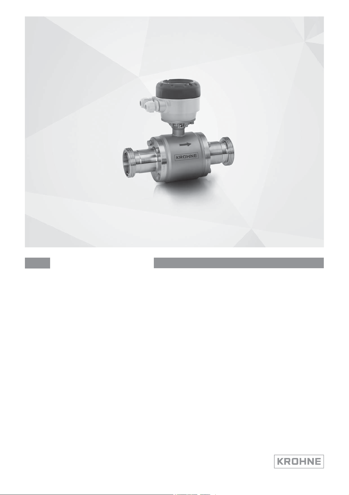
OPTIFLUX 6000
OPTIFLUX 6000
OPTIFLUX 6000OPTIFLUX 6000
HandbookHandbook
Electromagnetic flow sensor
for hygienic and sanitary applications
The documentation is only complete when used in combination with the relevant
documentation for the signal converter.
© KROHNE 02/2019 - 4001723706 - HB OPTIFLUX 6000 R07 en
Page 2

:
IMPRINT
:::::::::::::::::::::::::::::::::::::::
All rights reserved. It is prohibited to reproduce this documentation, or any part thereof, without
the prior written authorisation of KROHNE Messtechnik GmbH.
Subject to change without notice.
Copyright 2019 by
KROHNE Messtechnik GmbH - Ludwig-Krohne-Str. 5 - 47058 Duisburg (Germany)
2
www.krohne.com 02/2019 - 4001723706 - HB OPTIFLUX 6000 R07 en
Page 3

OPTIFLUX 6000
CONTENTS
1 Safety instructions 5
1.1 Intended Use..................................................................................................................... 5
1.2 Certification ...................................................................................................................... 5
1.3 Safety instructions from the manufacturer ..................................................................... 6
1.3.1 Copyright and data protection ................................................................................................ 6
1.3.2 Disclaimer ............................................................................................................................... 6
1.3.3 Product liability and warranty ................................................................................................ 7
1.3.4 Information concerning the documentation........................................................................... 7
1.3.5 Warnings and symbols used................................................................................................... 8
1.4 Safety instructions for the operator................................................................................. 8
2 Device description 9
2.1 Scope of delivery............................................................................................................... 9
2.2 Device description .......................................................................................................... 10
2.3 Nameplates (examples) ................................................................................................. 11
3 Installation 12
3.1 General notes on installation ......................................................................................... 12
3.2 Storage ........................................................................................................................... 12
3.3 Transport ........................................................................................................................ 12
3.4 Pre-installation requirements ....................................................................................... 13
3.5 General requirements.................................................................................................... 13
3.5.1 Vibration ................................................................................................................................ 13
3.5.2 Magnetic field........................................................................................................................ 13
3.6 Installation conditions ....................................................................................................14
3.6.1 Inlet and outlet...................................................................................................................... 14
3.6.2 Bends in 2 or 3 dimensions................................................................................................... 14
3.6.3 T-section ............................................................................................................................... 15
3.6.4 Bends .................................................................................................................................... 15
3.6.5 Open discharge ..................................................................................................................... 16
3.6.6 Control valve ......................................................................................................................... 16
3.6.7 Pump ..................................................................................................................................... 16
3.6.8 Air venting and vacuum forces ............................................................................................. 17
3.6.9 Mounting requirements for self-draining ............................................................................ 18
3.6.10 Flange deviation .................................................................................................................. 19
3.6.11 Mounting position................................................................................................................ 19
3.7 Mounting......................................................................................................................... 20
3.7.1 Torques and pressures......................................................................................................... 20
3.7.2 Installation of weld-on versions ........................................................................................... 21
4 Electrical connections 22
4.1 Safety instructions.......................................................................................................... 22
4.2 Grounding ....................................................................................................................... 22
4.3 Virtual reference for IFC 300 ( C, W and F version) ....................................................... 23
4.4 Connection diagrams ..................................................................................................... 23
www.krohne.com02/2019 - 4001723706 - HB OPTIFLUX 6000 R07 en
3
Page 4

CONTENTS
OPTIFLUX 6000
5 Service 24
5.1 Cleaning.......................................................................................................................... 24
5.2 Spare parts availability...................................................................................................24
5.3 Availability of services .................................................................................................... 24
5.4 Returning the device to the manufacturer..................................................................... 24
5.4.1 General information.............................................................................................................. 24
5.4.2 Form (for copying) to accompany a returned device............................................................ 25
5.5 Disposal .......................................................................................................................... 25
5.5.1 Disassembling and recycling................................................................................................ 25
6 Technical data 26
6.1 Measuring principle........................................................................................................26
6.2 Technical data................................................................................................................. 27
6.3 Measuring accuracy ....................................................................................................... 31
6.4 Dimensions and weights ................................................................................................ 33
7 Notes 47
4
www.krohne.com 02/2019 - 4001723706 - HB OPTIFLUX 6000 R07 en
Page 5
OPTIFLUX 6000
1.1 Intended Use
CAUTION!
Responsibility for the use of the measuring devices with regard to suitability, intended use and
corrosion resistance of the used materials against the measured fluid lies solely with the
operator.
INFORMATION!
The manufacturer is not liable for any damage resulting from improper use or use for other than
the intended purpose.
The OPTIFLUX 6000 is designed to measure the volumetric flowrate of electrically conductive
fluids in hygienic applications.
1.2 Certification
CE marking
SAFETY INSTRUCTIONS
1
The manufacturer certifies successful testing of the product by applying the CE marking.
This device fulfils the statutory requirements of the relevant EU directives.
For full information of the EU directives and standards and the approved certifications, please
refer to the EU Declaration of Conformity or the website of the manufacturer.
Other approvals and standards
• Measuring Instruments Directive 2014/32/EU, Annex III (MI-001), Annex VII (MI-005)
For more information, please refer to the dedicated documentation.
DANGER!
For devices used in hazardous areas, additional safety notes apply. Please refer to the Ex
documentation.
www.krohne.com02/2019 - 4001723706 - HB OPTIFLUX 6000 R07 en
5
Page 6

1
SAFETY INSTRUCTIONS
1.3 Safety instructions from the manufacturer
1.3.1 Copyright and data protection
The contents of this document have been created with great care. Nevertheless, we provide no
guarantee that the contents are correct, complete or up-to-date.
The contents and works in this document are subject to copyright. Contributions from third
parties are identified as such. Reproduction, processing, dissemination and any type of use
beyond what is permitted under copyright requires written authorisation from the respective
author and/or the manufacturer.
The manufacturer tries always to observe the copyrights of others, and to draw on works created
in-house or works in the public domain.
The collection of personal data (such as names, street addresses or e-mail addresses) in the
manufacturer's documents is always on a voluntary basis whenever possible. Whenever
feasible, it is always possible to make use of the offerings and services without providing any
personal data.
OPTIFLUX 6000
We draw your attention to the fact that data transmission over the Internet (e.g. when
communicating by e-mail) may involve gaps in security. It is not possible to protect such data
completely against access by third parties.
We hereby expressly prohibit the use of the contact data published as part of our duty to publish
an imprint for the purpose of sending us any advertising or informational materials that we have
not expressly requested.
1.3.2 Disclaimer
The manufacturer will not be liable for any damage of any kind by using its product, including,
but not limited to direct, indirect or incidental and consequential damages.
This disclaimer does not apply in case the manufacturer has acted on purpose or with gross
negligence. In the event any applicable law does not allow such limitations on implied warranties
or the exclusion of limitation of certain damages, you may, if such law applies to you, not be
subject to some or all of the above disclaimer, exclusions or limitations.
Any product purchased from the manufacturer is warranted in accordance with the relevant
product documentation and our Terms and Conditions of Sale.
The manufacturer reserves the right to alter the content of its documents, including this
disclaimer in any way, at any time, for any reason, without prior notification, and will not be liable
in any way for possible consequences of such changes.
6
www.krohne.com 02/2019 - 4001723706 - HB OPTIFLUX 6000 R07 en
Page 7

OPTIFLUX 6000
1.3.3 Product liability and warranty
The operator shall bear responsibility for the suitability of the device for the specific purpose.
The manufacturer accepts no liability for the consequences of misuse by the operator. Improper
installation or operation of the devices (systems) will cause the warranty to be void. The
respective "Standard Terms and Conditions" which form the basis for the sales contract shall
also apply.
1.3.4 Information concerning the documentation
To prevent any injury to the user or damage to the device it is essential that you read the
information in this document and observe applicable national standards, safety requirements
and accident prevention regulations.
If this document is not in your native language and if you have any problems understanding the
text, we advise you to contact your local office for assistance. The manufacturer can not accept
responsibility for any damage or injury caused by misunderstanding of the information in this
document.
This document is provided to help you establish operating conditions, which will permit safe and
efficient use of this device. Special considerations and precautions are also described in the
document, which appear in the form of icons as shown below.
SAFETY INSTRUCTIONS
1
www.krohne.com02/2019 - 4001723706 - HB OPTIFLUX 6000 R07 en
7
Page 8
1
SAFETY INSTRUCTIONS
1.3.5 Warnings and symbols used
Safety warnings are indicated by the following symbols.
DANGER!
This warning refers to the immediate danger when working with electricity.
DANGER!
This warning refers to the immediate danger of burns caused by heat or hot surfaces.
DANGER!
This warning refers to the immediate danger when using this device in a hazardous atmosphere.
DANGER!
These warnings must be observed without fail. Even partial disregard of this warning can lead to
serious health problems and even death. There is also the risk of seriously damaging the device
or parts of the operator's plant.
OPTIFLUX 6000
WARNING!
Disregarding this safety warning, even if only in part, poses the risk of serious health problems.
There is also the risk of damaging the device or parts of the operator's plant.
CAUTION!
Disregarding these instructions can result in damage to the device or to parts of the operator's
plant.
INFORMATION!
These instructions contain important information for the handling of the device.
LEGAL NOTICE!
This note contains information on statutory directives and standards.
• HANDLING
HANDLING
HANDLINGHANDLING
This symbol designates all instructions for actions to be carried out by the operator in the
specified sequence.
i
RESULT
RESULT
RESULTRESULT
This symbol refers to all important consequences of the previous actions.
1.4 Safety instructions for the operator
WARNING!
In general, devices from the manufacturer may only be installed, commissioned, operated and
maintained by properly trained and authorized personnel.
This document is provided to help you establish operating conditions, which will permit safe and
efficient use of this device.
8
www.krohne.com 02/2019 - 4001723706 - HB OPTIFLUX 6000 R07 en
Page 9
OPTIFLUX 6000
2.1 Scope of delivery
INFORMATION!
Inspect the packaging carefully for damages or signs of rough handling. Report damage to the
carrier and to the local office of the manufacturer.
INFORMATION!
Do a check of the packing list to make sure that you have all the elements given in the order.
INFORMATION!
The remote version will arrive in two cartons. One carton contains the converter and one carton
contains the sensor.
DEVICE DESCRIPTION
2
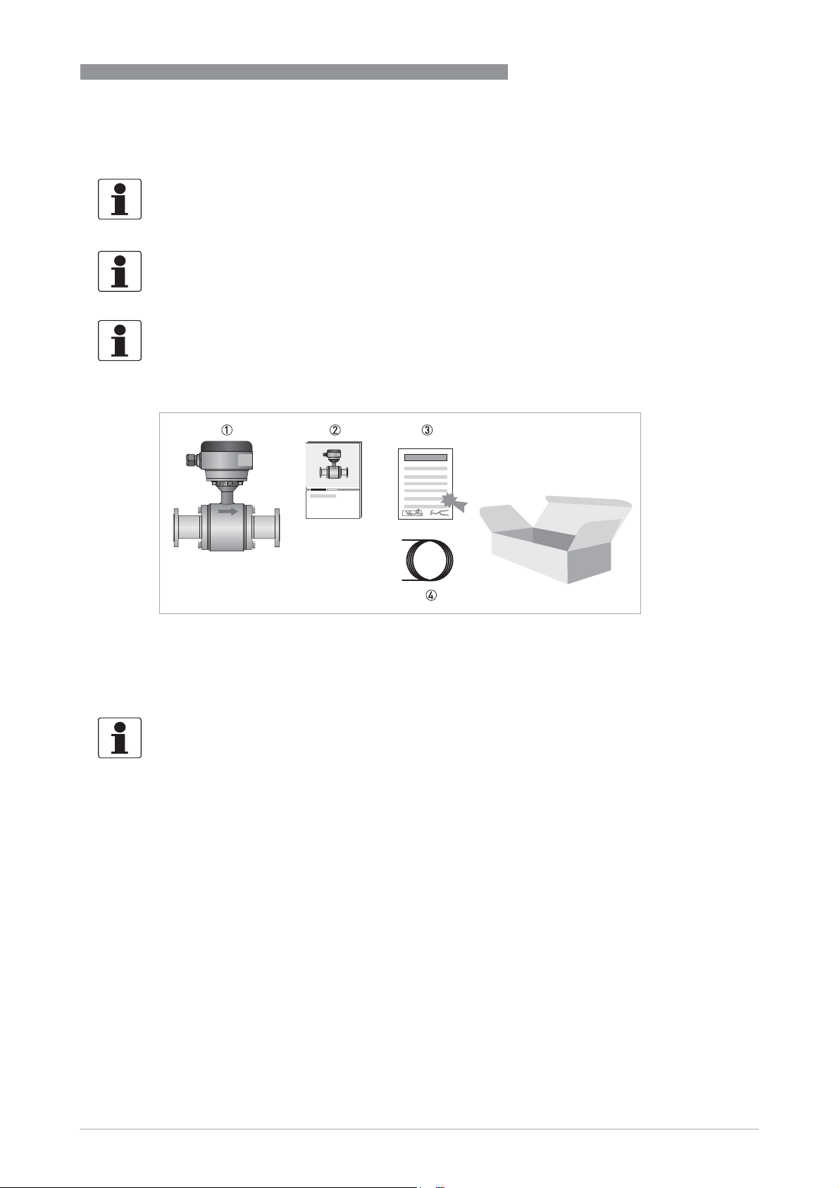
Figure 2-1: Scope of delivery
1 Ordered flowmeter
2 Product documentation
3 Factory calibration report
4 Signal cable (remote version only)
INFORMATION!
Assembly materials and tools are not part of the delivery. Use the assembly materials and tools
in compliance with the applicable occupational health and safety directives.
www.krohne.com02/2019 - 4001723706 - HB OPTIFLUX 6000 R07 en
9
Page 10
2
DEVICE DESCRIPTION
2.2 Device description
Your measuring device is supplied ready for operation. The factory settings for the operating
data have been made in accordance with your order specifications.
INFORMATION!
Product specific information and extensive product specification is available using PICK, the
Product Information Center KROHNE web-tool.
PICK can be found via the service menu button on the KROHNE.com website.
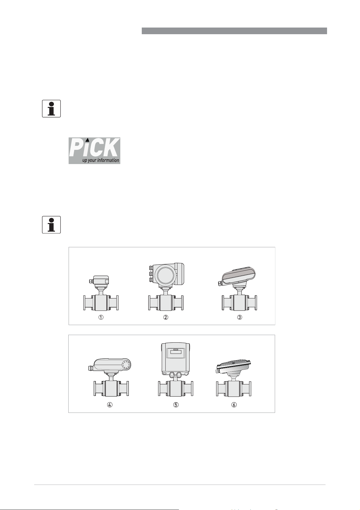
The following versions are available:
• Compact version (the signal converter is installed directly on the measuring sensor)
• Remote version (electrical connection to the signal converter via field current and signal
cable)
OPTIFLUX 6000
INFORMATION!
This flow sensor can be used as a remote version or as a compact version. All versions are
covered by this document, although you will see the remote version in most pictures.
10
Figure 2-2: Available versions
1 Remote version
2 Compact version with IFC 300 signal converter
3 Compact version with IFC 050 (10°) signal converter
4 Compact version with IFC 100 (0°) signal converter
5 Compact version with IFC 100 (45°) signal converter
6 Compact version with IFC 100 stainless steel signal converter (10°)
www.krohne.com 02/2019 - 4001723706 - HB OPTIFLUX 6000 R07 en
Page 11
OPTIFLUX 6000
2.3 Nameplates (examples)
INFORMATION!
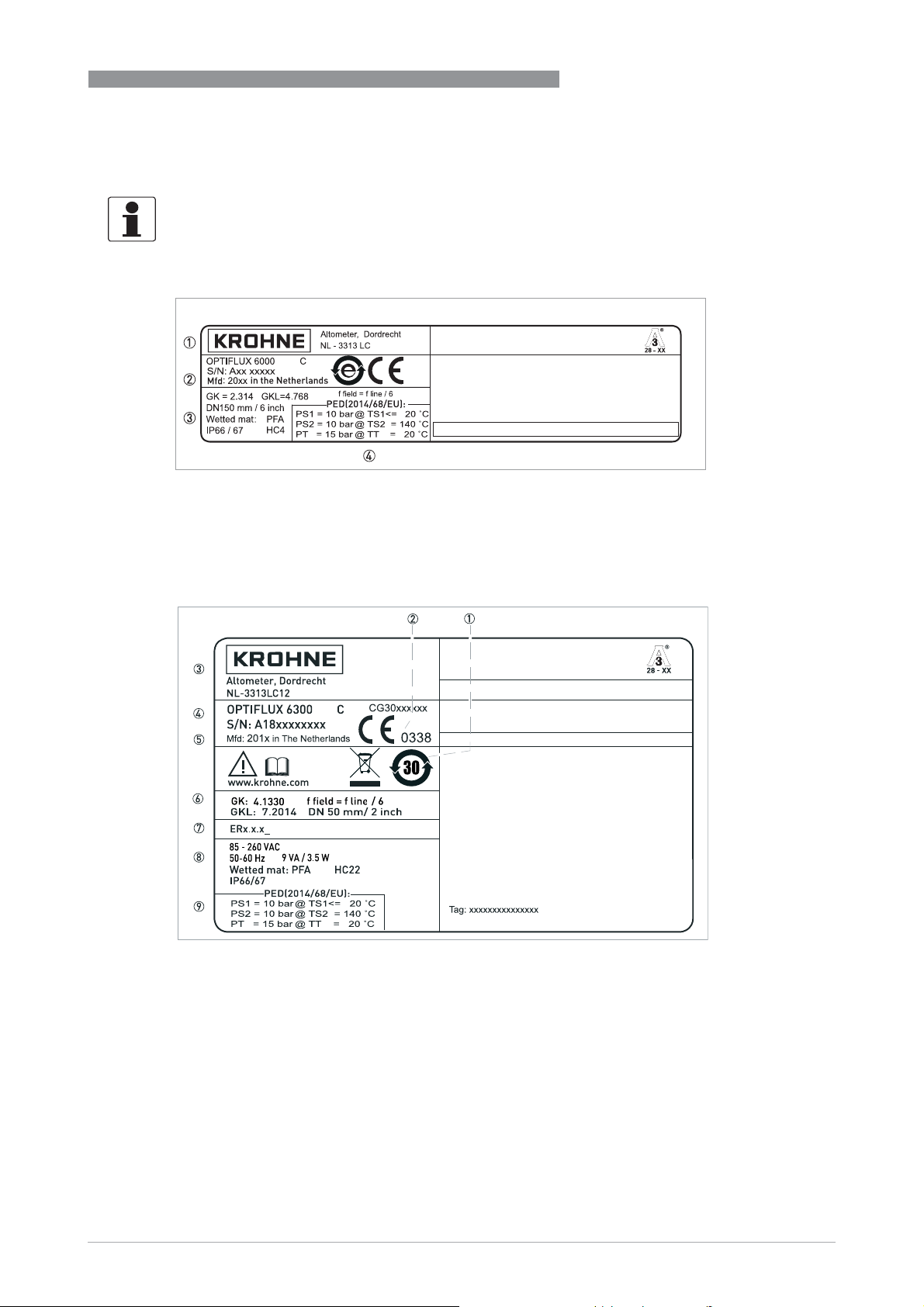
Look at the device nameplate to ensure that the device is delivered according to your order.
Check for the correct supply voltage printed on the nameplate.
Figure 2-3: Example of a nameplate on a sensor
1 Name and address of the manufacturer
2 Type designation of the flowmeter and CE sign with number(s) of notified body / bodies
3 Calibration data
4 PED dataCalibration data and protection category
DEVICE DESCRIPTION
2
Figure 2-4: Example of a nameplate for a compact version
1 Additional info, website and recycling logo
2 CE marking with number(s) of notified body (bodies)
3 Name and address of manufacturer
4 Type designation with serial / CG number
5 Manufacturing date and country of origin
6 GK/GKL values (measuring sensor constants), size (mm/inches), field frequency
7 Electronic Revision number
8 Electric values, protection category and materials of wetted parts
9 PED data type I/II/III or SEP
www.krohne.com02/2019 - 4001723706 - HB OPTIFLUX 6000 R07 en
11
Page 12
3
INSTALLATION
3.1 General notes on installation
INFORMATION!
Inspect the packaging carefully for damages or signs of rough handling. Report damage to the
carrier and to the local office of the manufacturer.
INFORMATION!
Do a check of the packing list to make sure that you have all the elements given in the order.
INFORMATION!
Look at the device nameplate to ensure that the device is delivered according to your order.
Check for the correct supply voltage printed on the nameplate.
3.2 Storage
• Store the device in a dry and dust-free location.
• Avoid lasting direct exposure to the sun.
• Store the device in its original packaging.
• Storage temperature: -50...+70°C / -58...+158°F
OPTIFLUX 6000
3.3 Transport
Signal converter
• No special requirements.
Compact version
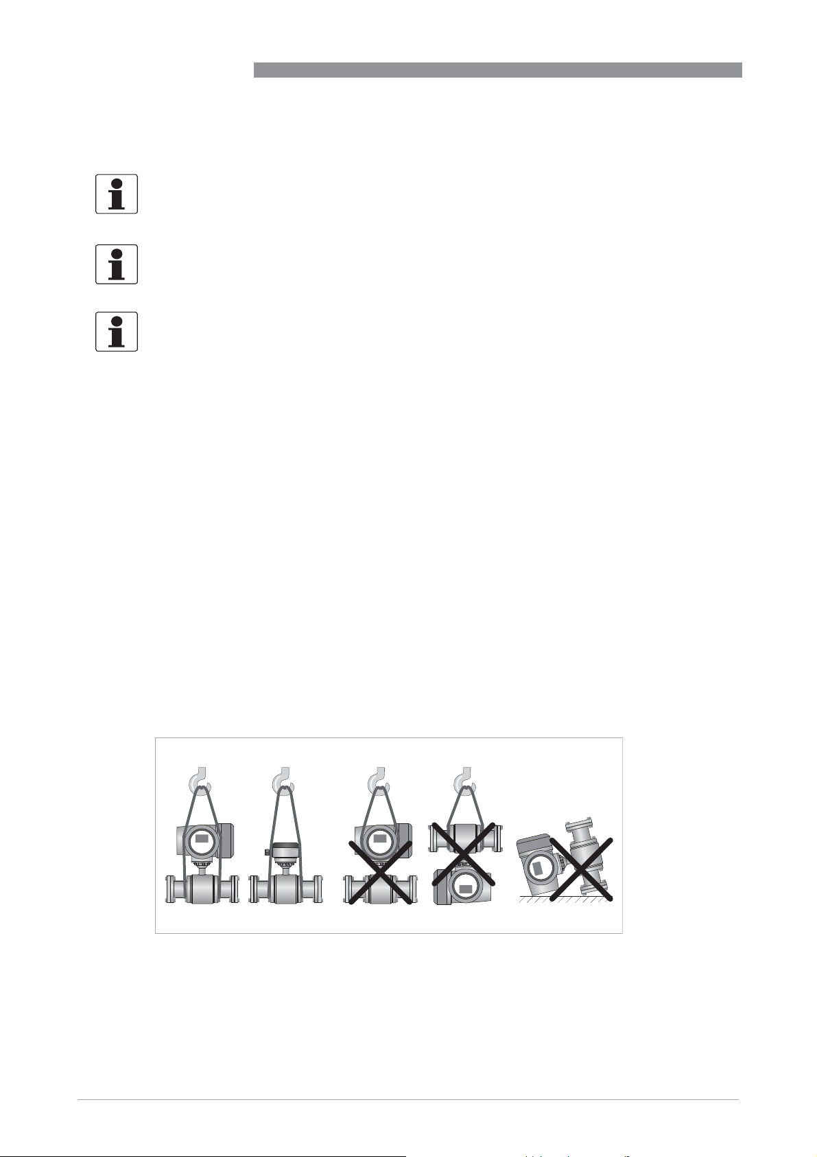
• Do not lift the device by the signal converter housing.
• Do not use lifting chains.
• To transport flange devices, use lifting straps. Wrap these around both process connections.
12
Figure 3-1: Transport
www.krohne.com 02/2019 - 4001723706 - HB OPTIFLUX 6000 R07 en
Page 13
OPTIFLUX 6000
3.4 Pre-installation requirements
Make sure that you have all necessary tools available:
• Allen key (4 mm)
• Small screwdriver
• Wrench for cable glands
• Wrench for wall mounting bracket (remote version only)
• Torque wrench for installing flowmeter in pipeline
3.5 General requirements
INFORMATION!
The following precautions must be taken to ensure reliable installation.
•
Make sure that there is adequate space to the sides.
•
Protect the signal converter from direct sunlight and install a sun shade if necessary.
•
Signal converters installed in control cabinets require adequate cooling, e.g. by fan or heat
exchanger.
•
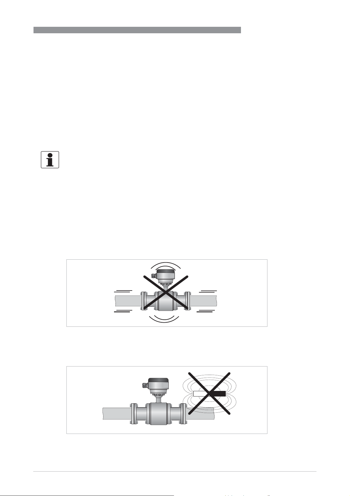
Do not expose the signal converter to intense vibration. The flowmeters are tested for a
vibration level in accordance with IEC 60068-2-64.
INSTALLATION
3
3.5.1 Vibration
Figure 3-2: Avoid vibrations
3.5.2 Magnetic field
Figure 3-3: Avoid magnetic fields
www.krohne.com02/2019 - 4001723706 - HB OPTIFLUX 6000 R07 en
13
Page 14
3
INSTALLATION
3.6 Installation conditions
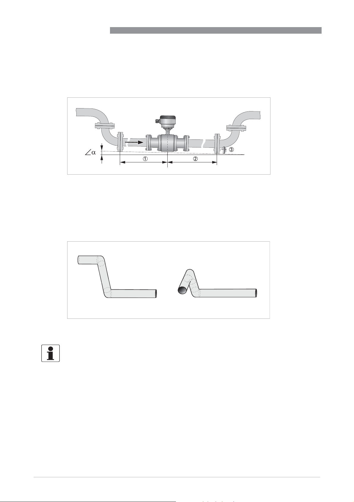
3.6.1 Inlet and outlet
Figure 3-4: Recommended inlet and outlet
1 Refer to chapter "Bends in 2 or 3 dimensions"
2 t 2 DN
3 Drain valve (to empty pipeline)
D ; >2°
OPTIFLUX 6000
3.6.2 Bends in 2 or 3 dimensions
Figure 3-5: Inlet when using 2 and/or 3 dimensional bends upstream of the flowmeter
Inlet length: using bends in 2 dimensions: t 5 DN; when having bends in 3 dimensions: t 10 DN
INFORMATION!
2 Dimensional bends occur in a vertical or
occur in both vertical and
and horizontal plane.
andand
or horizontal plane only, while 3 Dimensional bends
oror
14
www.krohne.com 02/2019 - 4001723706 - HB OPTIFLUX 6000 R07 en
Page 15
OPTIFLUX 6000
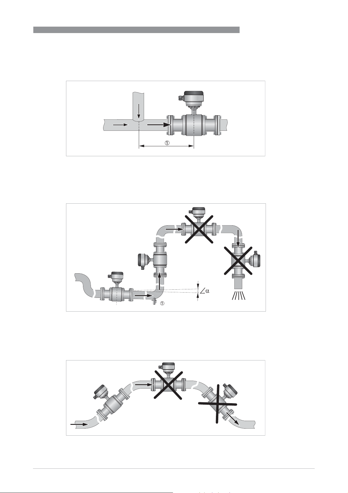
3.6.3 T-section
Figure 3-6: Distance behind a T-section
1 t 10 DN
3.6.4 Bends
INSTALLATION
3
Figure 3-7: Installation in bending pipes
D ; >2°
1 Drain valve (to empty pipeline)
Figure 3-8: Installation in bending pipes
www.krohne.com02/2019 - 4001723706 - HB OPTIFLUX 6000 R07 en
15
Page 16
3
INSTALLATION
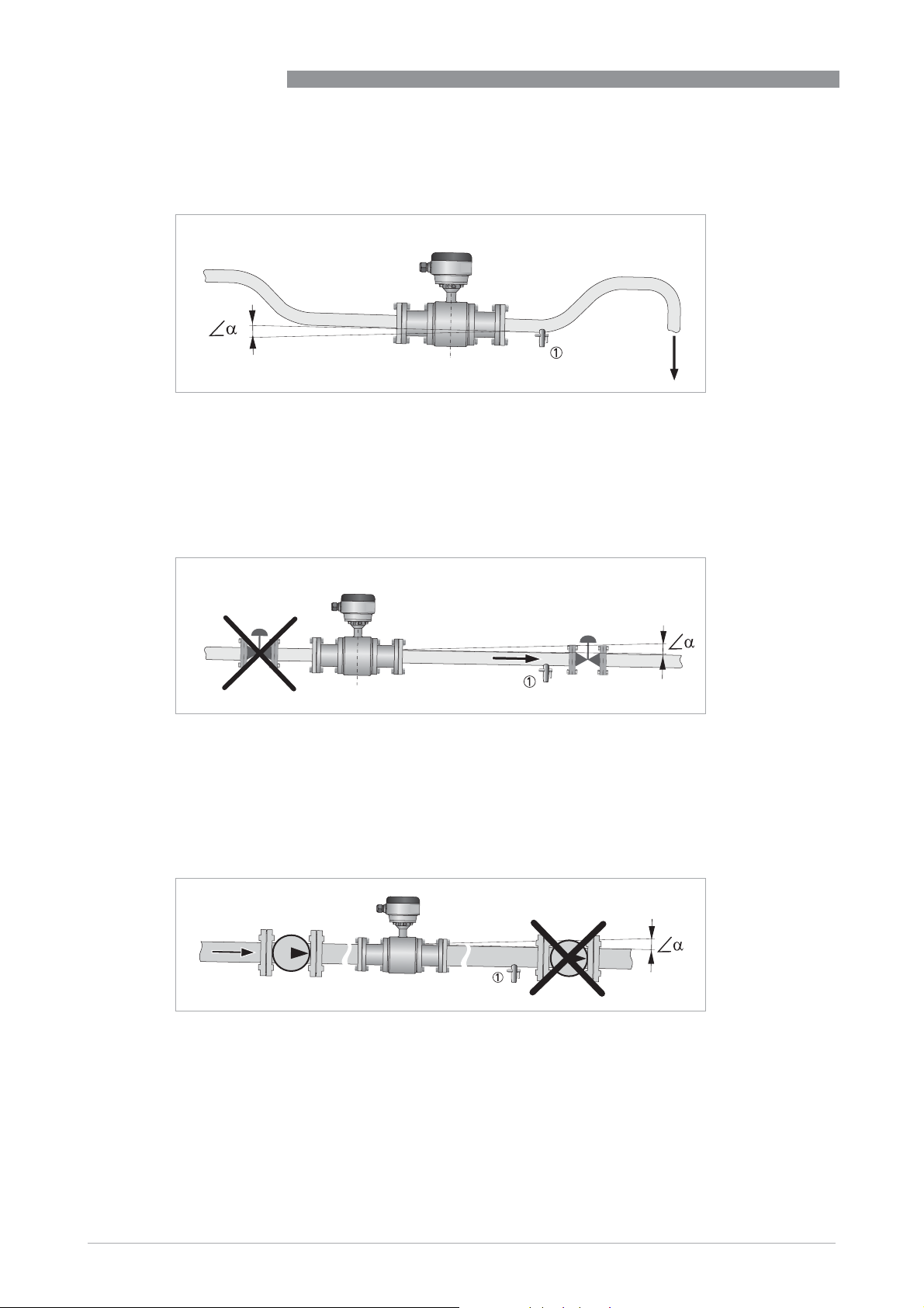
3.6.5 Open discharge
Figure 3-9: Installation in front of an open discharge
D ; >2°
1 Drain valve (to empty pipeline)
3.6.6 Control valve
OPTIFLUX 6000
3.6.7 Pump
Figure 3-10: Installation in front of a control valve
D ; >2°
1 Drain valve (to empty pipeline)
Figure 3-11: Installation behind a pump
16
www.krohne.com 02/2019 - 4001723706 - HB OPTIFLUX 6000 R07 en
Page 17
OPTIFLUX 6000
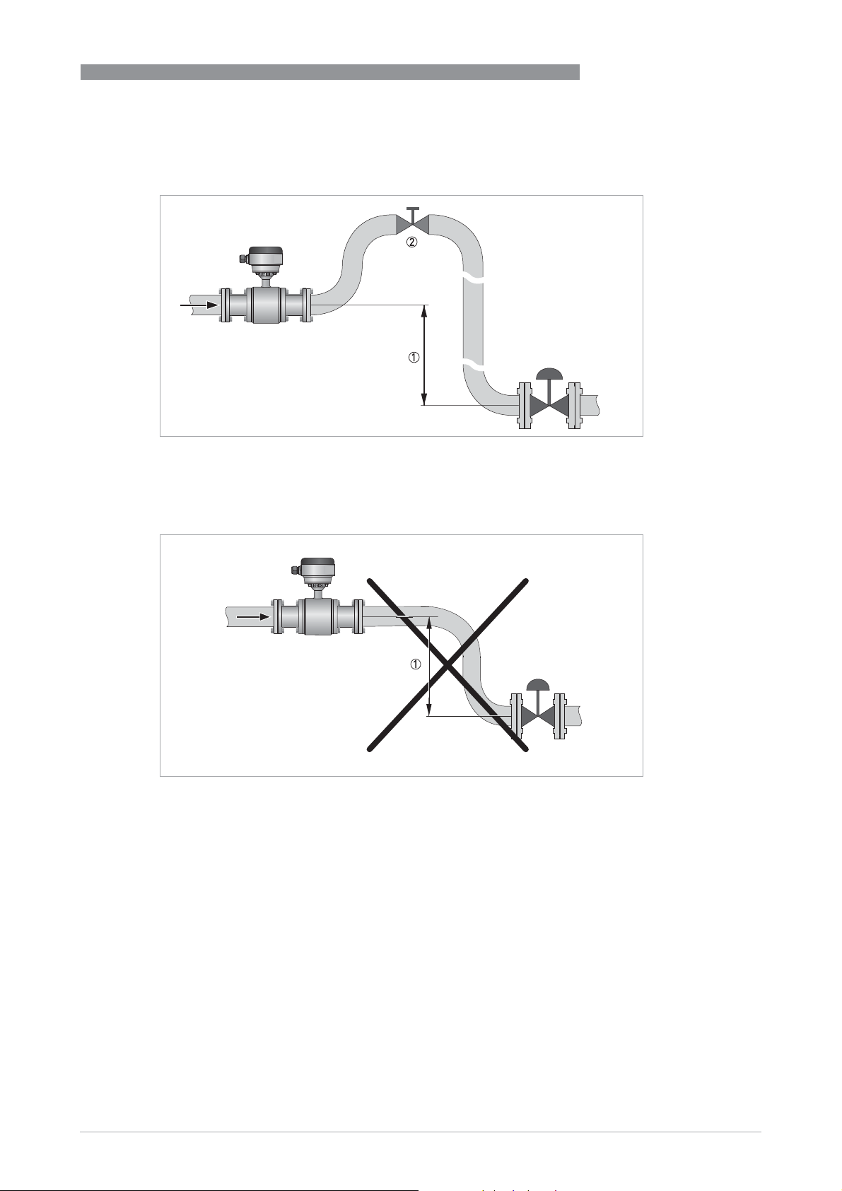
3.6.8 Air venting and vacuum forces
Figure 3-12: Air venting
1 t 5 m
2 Air ventilation point
INSTALLATION
3
Figure 3-13: Vacuum
1 t 5 m
www.krohne.com02/2019 - 4001723706 - HB OPTIFLUX 6000 R07 en
17
Page 18
3
INSTALLATION
3.6.9 Mounting requirements for self-draining
INFORMATION!
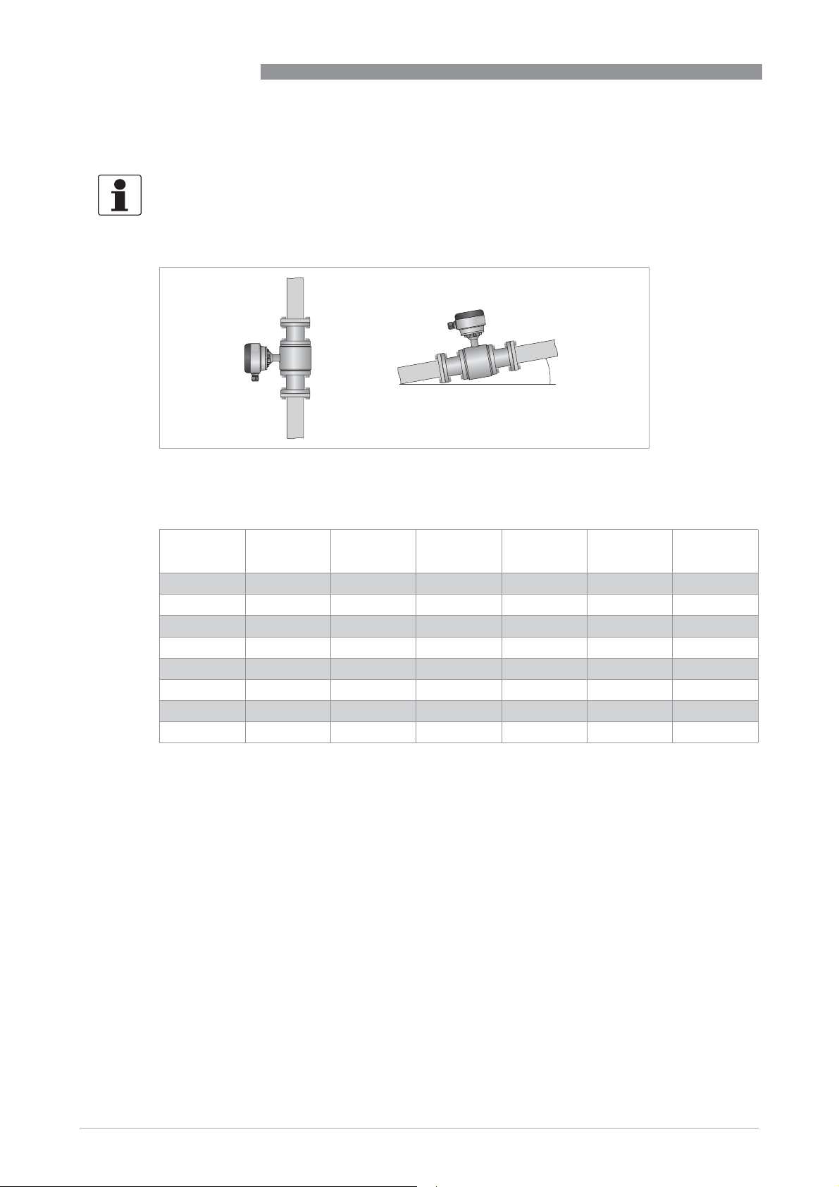
Applicable for 3A marked installations: install flow sensor in vertical pipelines or in pipelines
with a minimum slope as indicated!
Figure 3-14: Installation note for 3A marked installations
1 Minimum slope
OPTIFLUX 6000
1
Minimum slope
Nominal
diameter
2.5...6 10° 10° - - - -
10 3° 3° - - - -
15 10° 10° -
25 10° 3° 10° 3° 10° 3°
40...50 5° 3° 5° 3° 5° 3°
65...80 10° 3° 10° 3° 10° 3°
100 5° 3° 5° 3° 5° 3°
125...150 10° 3° 10° 3°
1 on request
DIN
11850
ISO
2037
DIN
11864 2A
ISO
2852
DIN
32676
1
- -
1 1
Tri
Clamp
18
www.krohne.com 02/2019 - 4001723706 - HB OPTIFLUX 6000 R07 en
Page 19
OPTIFLUX 6000
3.6.10 Flange deviation
CAUTION!
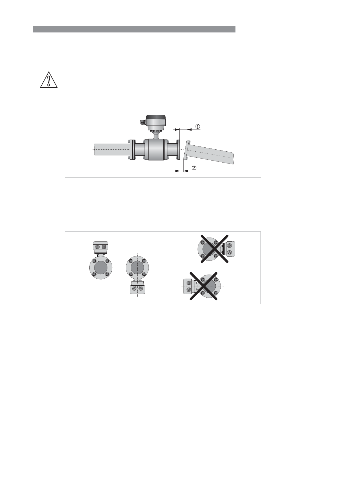
Max. permissible deviation of pipe flange faces:
L
- L
max
Figure 3-15: Flange deviation
1 L
max
2 L
min
d 0.5 mm / 0.02"
min
INSTALLATION
3
3.6.11 Mounting position
Figure 3-16: Mounting position
• Install flow sensor in line with the pipe axis.
• Pipe flange faces must be parallel to each other.
www.krohne.com02/2019 - 4001723706 - HB OPTIFLUX 6000 R07 en
19
Page 20
3
INSTALLATION
3.7 Mounting
3.7.1 Torques and pressures
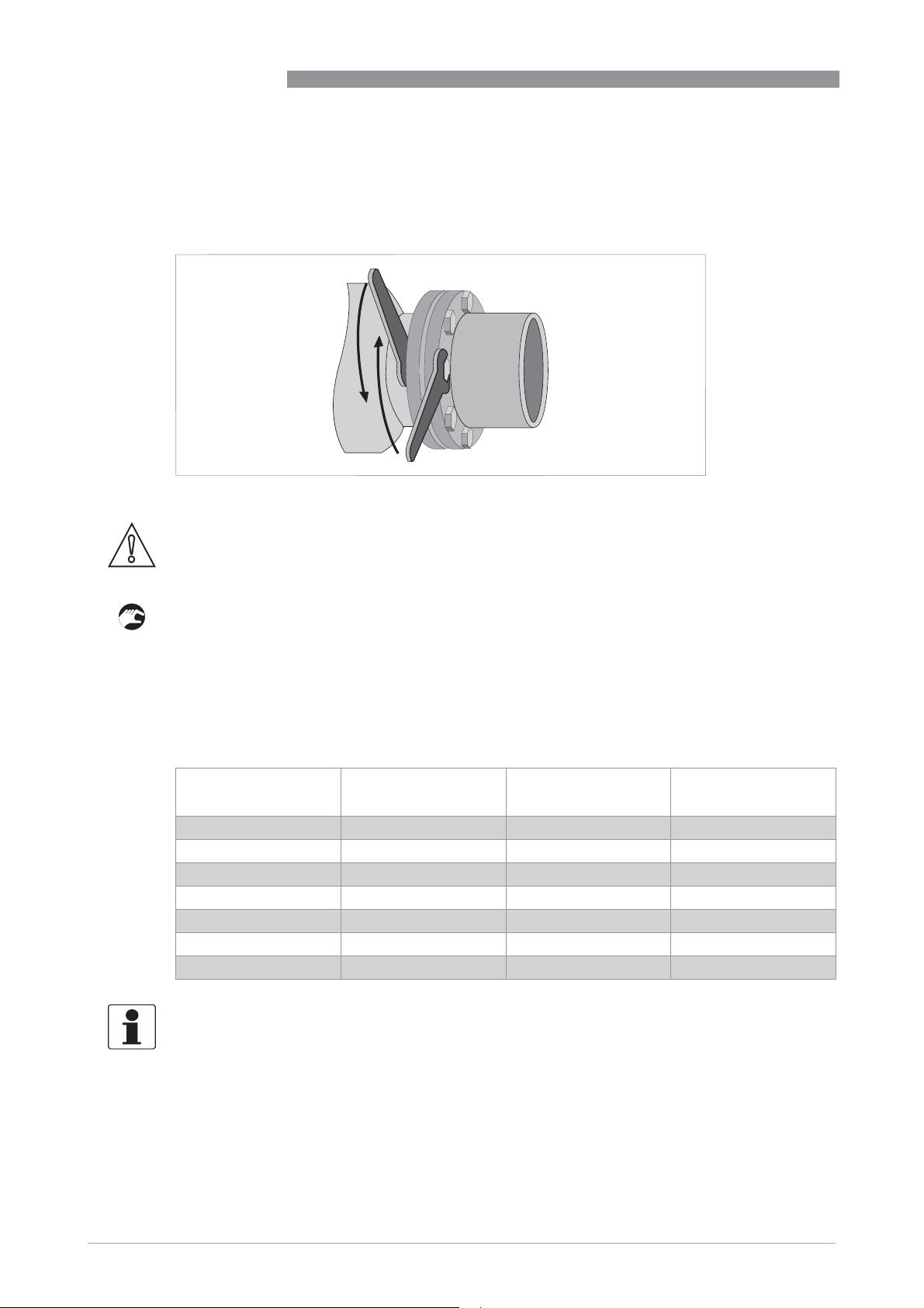
Figure 3-17: Tightening of bolts
CAUTION!
The max. allowable torque depends on the gasket material, see datasheet for detailed
information. Bolts to be used from material SS, class 70-A2.
OPTIFLUX 6000
Tightening of bolts
• Always tighten the bolts uniformly and in diagonally opposite sequence.
• Do not exceed the maximum torque value.
• Step 1: Apply approx. 50% of max. torque given in table.
• Step 2: Apply approx. 80% of max. torque given in table.
• Step 3: Apply 100% of max. torque given in table.
Maximum torque for 11864-2A flange version
Nominal diameter
[mm]
25 PN 40 4x M6 7
40 PN 40 4x M8 16
50 PN 25 4x M8 16
80 PN 25 6x M8 16
100 PN 25 6x M8 16
125 PN 10 6x M10 32
150 PN 10 6x M10 32
Pressure rating Bolts Max. torque
INFORMATION!
Maximum torque for sizes smaller than DN25: 6 Nm
[Nm]
20
www.krohne.com 02/2019 - 4001723706 - HB OPTIFLUX 6000 R07 en
Page 21

OPTIFLUX 6000
3.7.2 Installation of weld-on versions
For mounting sensors with weld-on connections, please follow the procedure as follows:
• Mount the sensor completely in the pipeline and spot the weld-on connections to the pipe. This
is necessary to align the mounting bores of the flange.
• Remove the sensor body and the gaskets from the adapters by loosen the screws.
• Weld the adapters completely to the pipe.
• When the pipe is cold again, reinstall the gasket and mount the sensor.
INSTALLATION
3
www.krohne.com02/2019 - 4001723706 - HB OPTIFLUX 6000 R07 en
21
Page 22
4
ELECTRICAL CONNECTIONS
4.1 Safety instructions
DANGER!
All work on the electrical connections may only be carried out with the power disconnected. Take
note of the voltage data on the nameplate!
DANGER!
Observe the national regulations for electrical installations!
DANGER!
For devices used in hazardous areas, additional safety notes apply; please refer to the Ex
documentation.
WARNING!
Observe without fail the local occupational health and safety regulations. Any work done on the
electrical components of the measuring device may only be carried out by properly trained
specialists.
OPTIFLUX 6000
INFORMATION!
Look at the device nameplate to ensure that the device is delivered according to your order.
Check for the correct supply voltage printed on the nameplate.
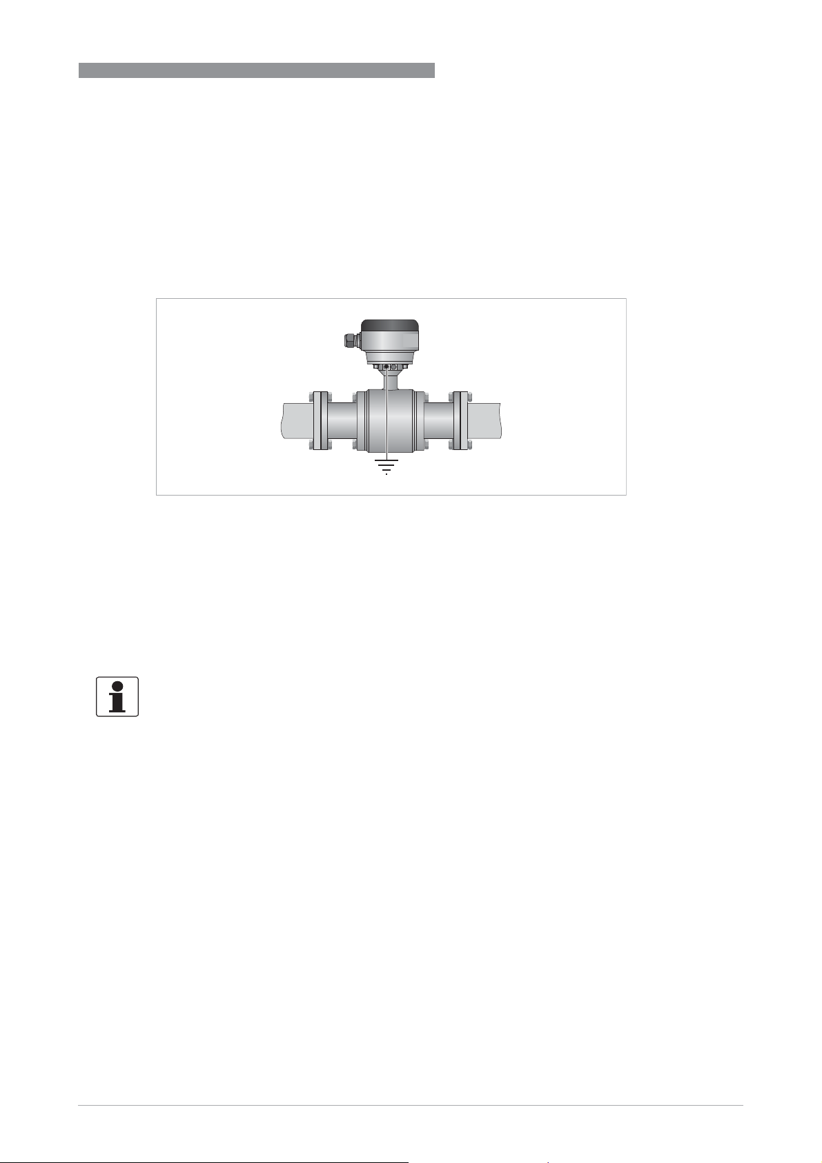
4.2 Grounding
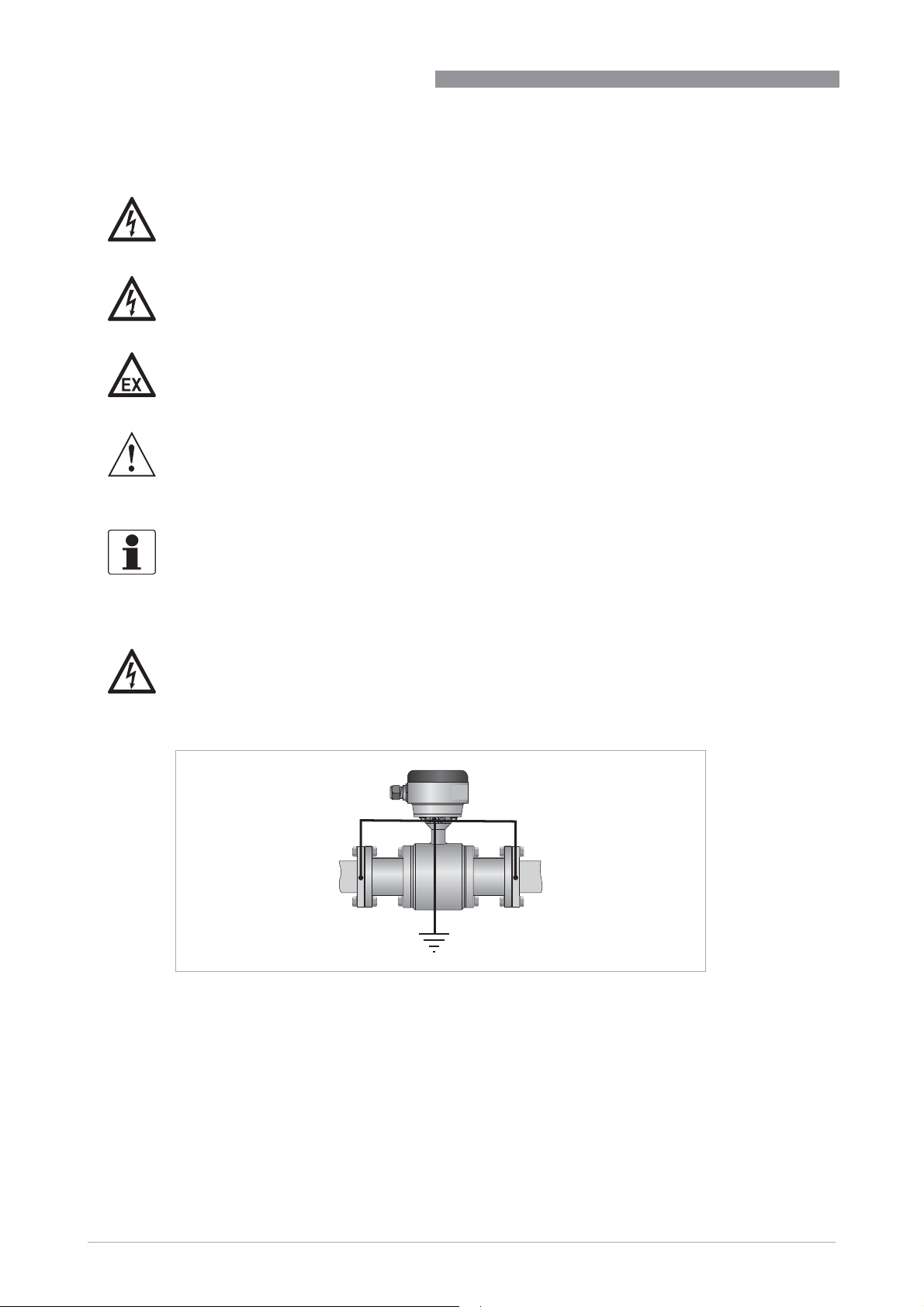
DANGER!
The device must be grounded in accordance with regulations in order to protect personnel
against electric shocks.
Figure 4-1: Grounding
22
www.krohne.com 02/2019 - 4001723706 - HB OPTIFLUX 6000 R07 en
Page 23
OPTIFLUX 6000
ELECTRICAL CONNECTIONS
4.3 Virtual reference for IFC 300 ( C, W and F version)
Benefits of virtual reference:
• Grounding rings or grounding electrodes can be omitted.
• Safety increases by reducing the number of potential leakage points.
• The installation of the flowmeters is much easier.
4
Figure 4-2: Virtual reference
Minimum requirements:
• Size: t DN10 / 3/8"
• Electrical conductivity: t 200 μS/cm
• Electrode cable: max. 50 m / 164 ft, type DS
4.4 Connection diagrams
INFORMATION!
For the connection diagrams the documentation of the applicable signal converter.
www.krohne.com02/2019 - 4001723706 - HB OPTIFLUX 6000 R07 en
23
Page 24
5
SERVICE
5.1 Cleaning
CAUTION!
In principle, no special maintenance is needed. However, make sure that the used cleaning
product doesn't affect the outer surface and the gaskets.
5.2 Spare parts availability
The manufacturer adheres to the basic principle that functionally adequate spare parts for each
device or each important accessory part will be kept available for a period of 3 years after
delivery of the last production run for the device.
This regulation only applies to spare parts which are subject to wear and tear under normal
operating conditions.
5.3 Availability of services
The manufacturer offers a range of services to support the customer after expiration of the
warranty. These include repair, maintenance, technical support and training.
OPTIFLUX 6000
INFORMATION!
For more precise information, please contact your local sales office.
5.4 Returning the device to the manufacturer
5.4.1 General information
This device has been carefully manufactured and tested. If installed and operated in accordance
with these operating instructions, it will rarely present any problems.
WARNING!
Should you nevertheless need to return a device for inspection or repair, please pay strict
attention to the following points:
•
Due to statutory regulations on environmental protection and safeguarding the health and
safety of the personnel, the manufacturer may only handle, test and repair returned devices
that have been in contact with products without risk to personnel and environment.
•
This means that the manufacturer can only service this device if it is accompanied by the
following certificate (see next section) confirming that the device is safe to handle.
WARNING!
If the device has been operated with toxic, caustic, radioactive, flammable or water-endangering
products, you are kindly requested:
•
to check and ensure, if necessary by rinsing or neutralising, that all cavities are free from
such dangerous substances,
•
to enclose a certificate with the device confirming that it is safe to handle and stating the
product used.
24
www.krohne.com 02/2019 - 4001723706 - HB OPTIFLUX 6000 R07 en
Page 25
OPTIFLUX 6000
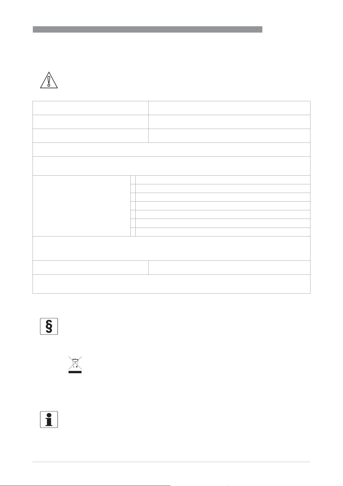
5.4.2 Form (for copying) to accompany a returned device
CAUTION!
To avoid any risk for our service personnel, this form has to be accessible from outside of the
packaging with the returned device.
Company: Address:
Department: Name:
Tel. no.: Fax no. and/or Email address:
Manufacturer's order no. or serial no.:
The device has been operated with the following medium:
This medium is: radioactive
water-hazardous
toxic
caustic
flammable
We checked that all cavities in the device are free from such substances.
We have flushed out and neutralized all cavities in the device.
SERVICE
5
We hereby confirm that there is no risk to persons or the environment through any residual media contained in the
device when it is returned.
Date: Signature:
Stamp:
5.5 Disposal
LEGAL NOTICE!
Disposal must be carried out in accordance with legislation applicable in your country.
Separate collection of WEEE (Waste Electrical and Electronic Equipment) in the European Union:
Separate collection of WEEE (Waste Electrical and Electronic Equipment) in the European Union:
Separate collection of WEEE (Waste Electrical and Electronic Equipment) in the European Union:Separate collection of WEEE (Waste Electrical and Electronic Equipment) in the European Union:
According to the directive 2012/19/EU, the monitoring and control instruments marked with the
WEEE symbol and reaching their end-of-life must not be disposed of with other waste
The user must dispose of the WEEE to a designated collection point for the recycling of WEEE or
send them back to our local organisation or authorised representative.
5.5.1 Disassembling and recycling
must not be disposed of with other waste.
must not be disposed of with other wastemust not be disposed of with other waste
INFORMATION!
For information about disassembling and recycling, refer to the applicable documentation of the
measuring converter or consult product support for the product recycling passport.
www.krohne.com02/2019 - 4001723706 - HB OPTIFLUX 6000 R07 en
25
Page 26
6
TECHNICAL DATA
6.1 Measuring principle
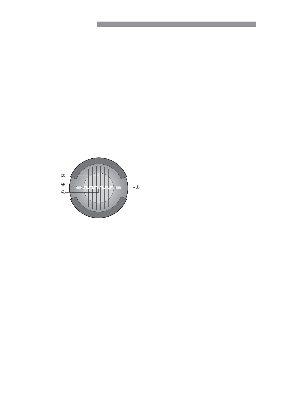
An electrically conductive fluid flows inside an electrically insulated pipe through a magnetic
field. This magnetic field is generated by a current, flowing through a pair of field coils.
Inside of the fluid, a voltage U is generated:
U = v * k * B * D
U = v * k * B * D
U = v * k * B * DU = v * k * B * D
in which:
v = mean flow velocity
k = factor correcting for geometry
B = magnetic field strength
D = inner diameter of flowmeter
The signal voltage U is picked off by electrodes and is proportional to the mean flow velocity v
and thus the flow rate Q. A signal converter is used to amplify the signal voltage, filter it and
convert it into signals for totalizing, recording and output processing.
OPTIFLUX 6000
Figure 6-1: Measuring principle
1 Field coils
2 Magnetic field
3 Electrodes
4 Induced voltage (proportional to flow velocity)
26
www.krohne.com 02/2019 - 4001723706 - HB OPTIFLUX 6000 R07 en
Page 27
OPTIFLUX 6000
6.2 Technical data
INFORMATION!
•
The following data is provided for general applications. If you require data that is more
relevant to your specific application, please contact us or your local sales office.
•
Additional information (certificates, special tools, software,...) and complete product
documentation can be downloaded free of charge from the website (Downloadcenter).
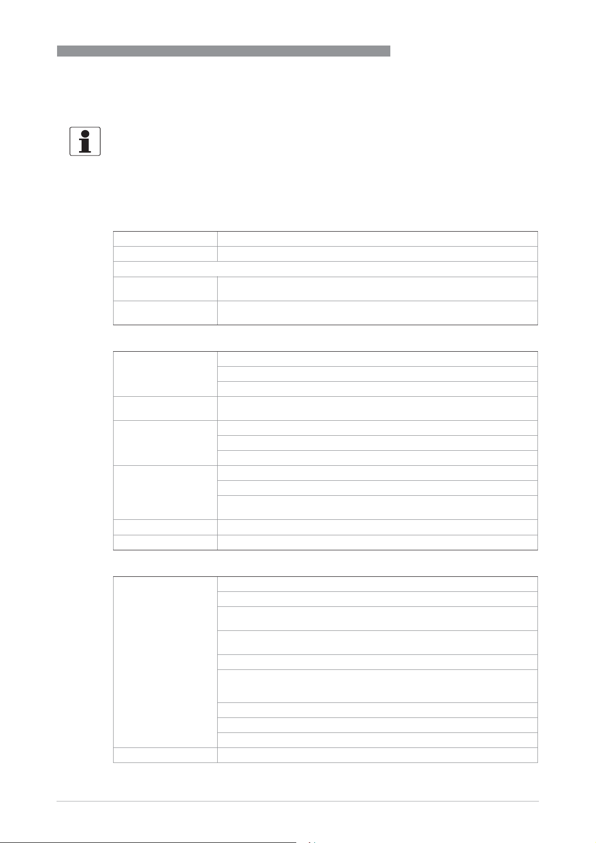
Measuring system
Measuring principle Faraday's law of induction
Application range Electrically conductive fluids
Measured value
Measured value
Measured valueMeasured value
Primary measured
value
Secondary measured
value
Flow velocity
Volume flow
TECHNICAL DATA
6
Design
Features Hygienic design
Stainless steel housing
Food & beverage and pharmaceutical process connections
Modular construction The measurement system consists of a flow sensor and a signal converter.
Compact version With IFC 050 signal converter: OPTIFLUX 6050 C
Remote version In wall (W) mount version with IFC 050 signal converter: OPTIFLUX 6050 W
Nominal diameter DN2.5...150 / ¹/10"...6"
Measuring range -12...+12 m/s / -40...+40 ft/s
It is available as compact and as separate version.
With IFC 100 signal converter: OPTIFLUX 6100 C
With IFC 300 signal converter: OPTIFLUX 6300 C
In wall (W) mount version with IFC 100signal converter: OPTIFLUX 6100 W
In field (F), wall (W) or rack (R) mount version with IFC 300 signal converter:
OPTIFLUX 6300 F, W or R
Measuring accuracy
Maximum measuring
error
Repeatability ±0.1% of MV, minimum 1 mm/s
Depending on signal converter and DN size.
IFC 050: down to 0.5% of the measured value ± 1 mm/s.
IFC 100: down to 0.3% of the measured value ± 1 mm/s for DN10...150 (³/8...6").
down to 0.4% of the measured value ± 1 mm/s for DN2.5...6 (¹/10...¼").
IFC 300: down to 0.2% of the measured value ± 1 mm/s for DN10...150 (³/8...6").
down to 0.3% of the measured value ± 2 mm/s for DN2.5...6 (¹/10...¼").
Optional:
Optional:
Optional:Optional:
Optimised accuracy for IFC 050 and IFC 100.
For more details on optimised accuracy, see the concerning signal converter
documentation.
The additional typical measuring deviation for the current output is ±10 μA.
The maximum measuring error depends on the installation conditions.
For detailed information refer to
Measuring accuracy
on page 31.
www.krohne.com02/2019 - 4001723706 - HB OPTIFLUX 6000 R07 en
27
Page 28

6
TECHNICAL DATA
Long term stability ±0.1% of MV
Special calibration On request
Operating conditions
Temperature
Temperature
TemperatureTemperature
Process temperature Separate flow sensor: -40...+140°C / -40...+284°F
Ambient temperature -40...+65°C / -40...+149°F
Storage temperature -50...+70°C / -58...+158°F
Pressure
Pressure
PressurePressure
Ambient pressure Atmospheric
Nominal flange
pressure
Vacuum load 0 mbar / 0 psi
Chemical properties
Chemical properties
Chemical propertiesChemical properties
Physical condition Electrical conductive liquids
Electrical conductivity Standard: t 1 PS/cm
Permissible gas
content
(volume)
Permissible solid
content
(volume)
OPTIFLUX 6000
Compact with IFC 300 converter: -40...+140°C / -40...+284°F
Compact with IFC 050 and IFC 100 converter: -40...+120°C / -40...+248°F
at an ambient temperature d 40 °C / 104 °F
For ISO 2852 and Tri-clamp versions: -40...+120°C / -40...+248°F
For Ex versions different temperatures are valid.
Please check the relevant Ex documentation for details.
IFC 100 stainless steel version: -40...+60°C / -40...+140°F
For detailed information refer to
Water: t 20 PS/cm
IFC 050: d 3%
IFC 100: d 3%
IFC 300: d 5%
IFC 050: d 10%
IFC 100: d 10%
IFC 300: d 70%
Dimensions and weights
on page 33.
28
Installation conditions
Installation Assure that the flow sensor is always fully filled.
For detailed information refer to
Flow direction Forward and reverse
Arrow on flow sensor indicates positive flow direction.
Inlet run t 5 DN
Outlet run t 2 DN
Dimensions and
weights
For detailed information refer to
www.krohne.com 02/2019 - 4001723706 - HB OPTIFLUX 6000 R07 en
Installation
Dimensions and weights
on page 12.
on page 33.
Page 29

OPTIFLUX 6000
Materials
Sensor housing DN2.5...15: stainless steel Duplex (1.4462)
Measuring tube Stainless steel AISI 304 (1.4301)
Adapters Stainless steel AISI 316 L (1.4404)
Liner PFA
Connection box
(F-version only)
Electrodes Standard:
Gaskets Standard:
TECHNICAL DATA
DN25...150: stainless steel AISI 304 (1.4301)
Other materials on request.
Standard:
Standard:
Standard:Standard:
Aluminum with a standard coating
Option:
Option:
Option:Option:
Stainless steel AISI (1.4408)
Standard:
Standard:Standard:
Hastelloy® C
Option:
Option:
Option:Option:
Hastelloy® B2, platinum, stainless steel, tantalum, titanium
Standard:
Standard:Standard:
EPDM
FDA recommends EPDM gaskets only if medium d 8% fat.
Option:
Option:
Option:Option:
Silicone (non-Ex only)
6
Process connections
DIN 11850 row 2
/ 11866 row A
DIN 11851 DN2.5...150
DIN 11864-2A
flange with notch
DIN 32676 DN25...150
ISO 2037 DN2.5...150
ISO 2852 DN2.5...150
SMS 1146 DN2.5...100
Tri Clamp ¹/10"...6"
Note: sensor diameters < DN10 have DN10 connections, which means the sensor diameter is smaller.
DN2.5...150
DN25...150
Electrical connections
Signal cable
Signal cable
Signal cableSignal cable
Type A (DS) Standard cable, double shielded.
Type B (BTS) Optional cable, triple shielded.
Max. length: 600 m / 1950 ft (dep. on electrical conductivity and measuring
sensor). See documentation of the converter for more information.
Max. length: 600 m / 1950 ft (dep. on electrical conductivity and measuring
sensor). See documentation of the converter for more information.
www.krohne.com02/2019 - 4001723706 - HB OPTIFLUX 6000 R07 en
29
Page 30

6
TECHNICAL DATA
Approvals and certificates
CE
CE
CECE
This device fulfills the statutory requirements of the EU directives.
The manufacturer certifies successful testing of the product by applying the CE mark.
Hazardous areas
Hazardous areas
Hazardous areasHazardous areas
ATEX Please check the relevant Ex documentation for details.
FM In combination with IFC 300 C or F converter:
CSA In combination with IFC 300 C or F converter:
Other approvals and standards
Other approvals and standards
Other approvals and standardsOther approvals and standards
Protection category acc. to
IEC/EN 60529
Hygienic 3A approved
Shock test IEC 60068-2-27
Vibration test IEC 60068-2-64
OPTIFLUX 6000
For full information of the EU directives and standards and the approved
certifications, please refer to the EU Declaration of Conformity or the
website of the manufacturer.
Compact version with IFC 300 C converter:
Compact version with IFC 300 C converter:
Compact version with IFC 300 C converter:Compact version with IFC 300 C converter:
II 2 G, II D, II 2 (1) G
Remote (F) version:
Remote (F) version:
Remote (F) version:Remote (F) version:
II 2 G, II 2 D
In combination with IFC 300 C or F converter:
In combination with IFC 300 C or F converter:In combination with IFC 300 C or F converter:
Class I, Div. 2, Groups A, B, C and D
Class II, Div. 2, Groups F and G
Class III, Div. 2, Groups F and G
Only available for DN2.5...15
In combination with IFC 300 C or F converter:
In combination with IFC 300 C or F converter:In combination with IFC 300 C or F converter:
Class I, Div. 2, Groups A, B, C and D
Class II, Div. 2, Groups F and G
Class III, Div. 2, Groups F and G
Only available for DN2.5...15
Standard
Standard
StandardStandard
IP 66/67 (NEMA 4/4X/6)
Option (F version only)
Option (F version only)
Option (F version only)Option (F version only)
IP 68 field (NEMA 6P)
IP 68 factory (NEMA 6P)
IP 68 is only available for separate design and with a stainless steel
connection box.
Option IP69
Option IP69
Option IP69Option IP69
IP 67/69 is available for connection box and IFC 100 in stainless steel.
EHEDG
30 g for 18 ms
f = 20...2000 Hz, rms = 4.5 g, t = 30 min.
30
www.krohne.com 02/2019 - 4001723706 - HB OPTIFLUX 6000 R07 en
Page 31
OPTIFLUX 6000
6.3 Measuring accuracy
Every electromagnetic flowmeter is calibrated by direct volume comparison. The wet calibration
validates the performance of the flowmeter under reference conditions against accuracy limits.
The accuracy limits of electromagnetic flowmeters are typically the result of the combined effect
of linearity, zero point stability and calibration uncertainty.
Reference conditions
• Medium: water
• Temperature: +5...35°C / +41...95°F
• Operating pressure: 0.1...5 barg / 1.5...72.5 psig
• Inlet section: t 5 DN
• Outlet section: t 2 DN
TECHNICAL DATA
6
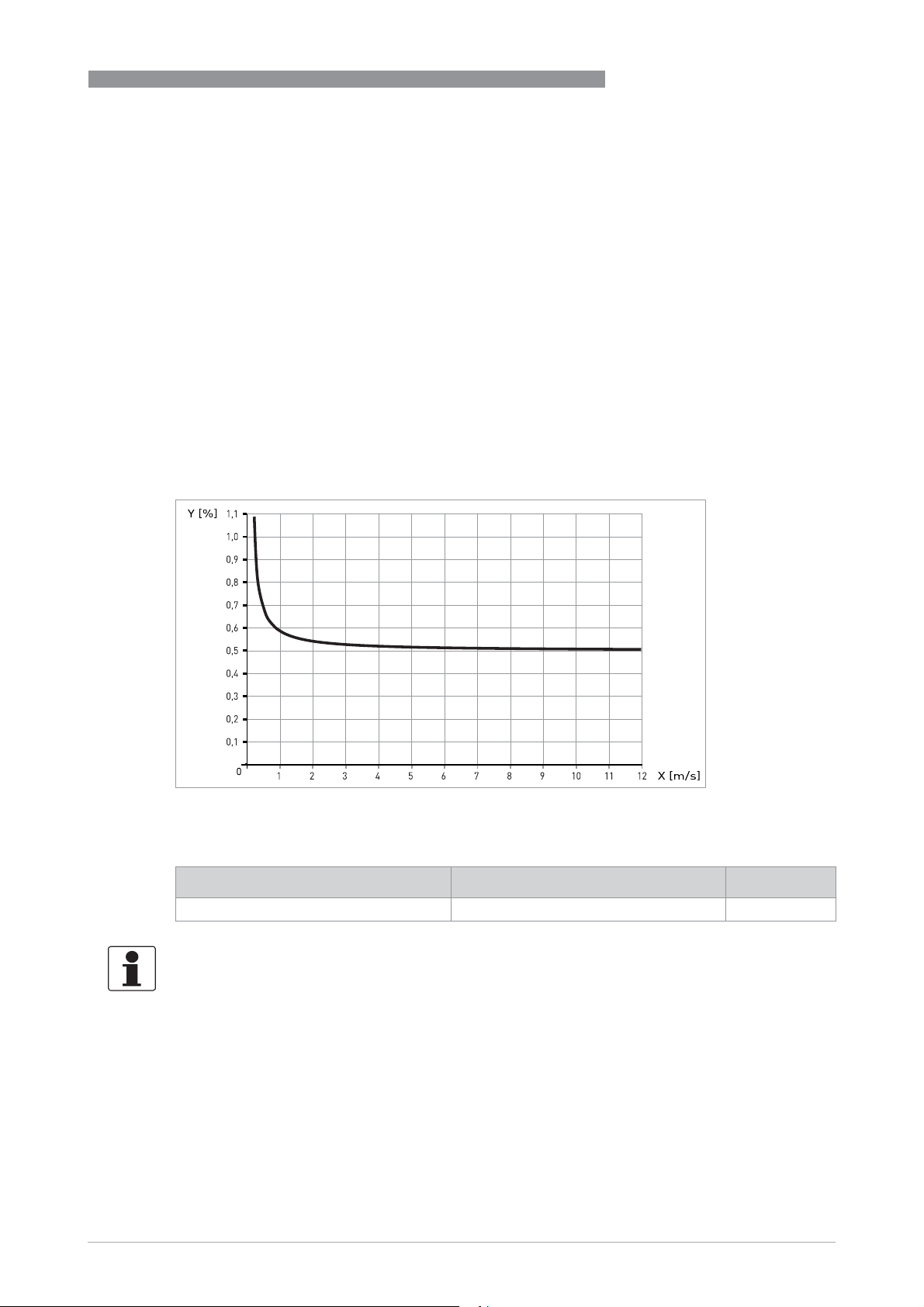
Figure 6-2: Flow velocity vs. accuracy
X [m/s] : flow velocity
Y [%]: deviation from the actual measured value (mv)
Compact with IFC 050 Accuracy Curve
DN10...150 / 3/8...6" 0.5% of MV + 1 mm/s
INFORMATION!
Optionally for IFC 050; extended calibration at 2 points for optimised accuracy.
For more details on optimised accuracy, see the concerning signal converter documentation.
www.krohne.com02/2019 - 4001723706 - HB OPTIFLUX 6000 R07 en
31
Page 32
6
TECHNICAL DATA
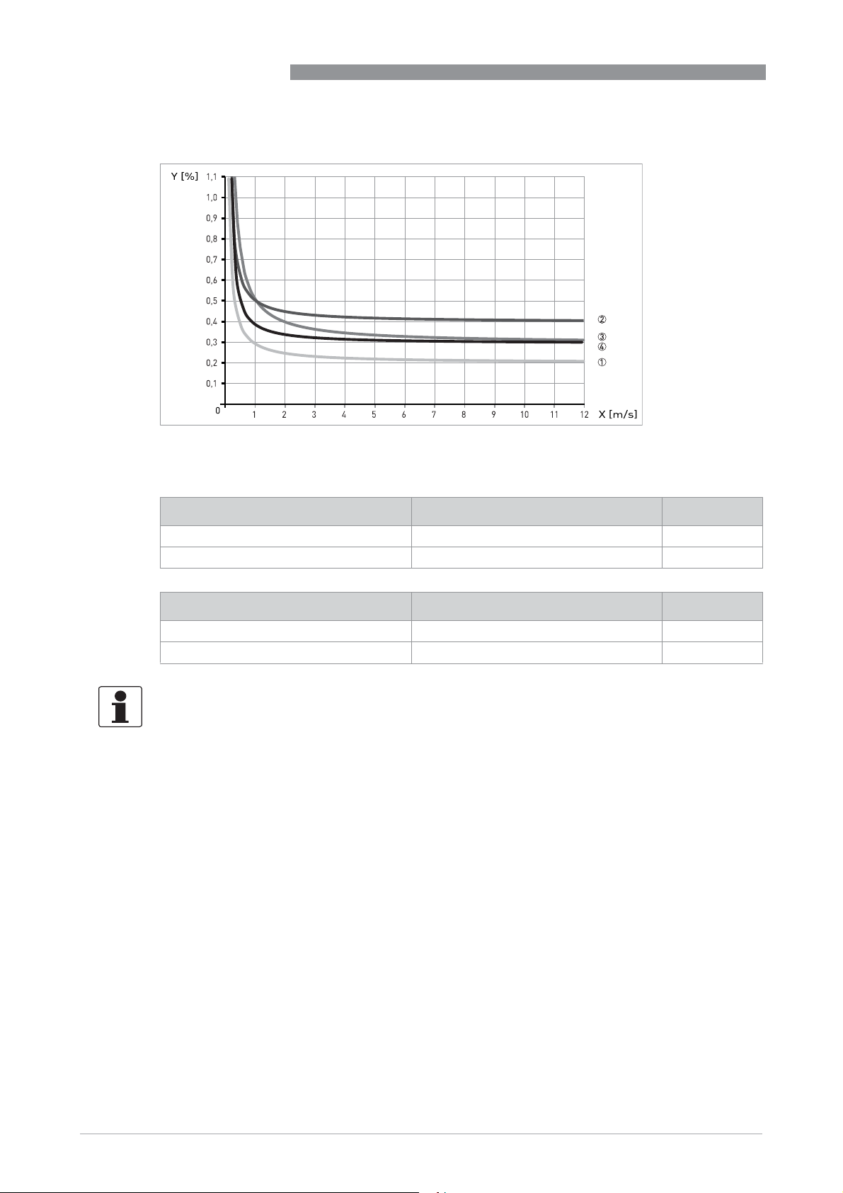
Figure 6-3: Flow velocity vs. accuracy
X [m/s] : flow velocity
Y [%]: deviation from the actual measured value (mv)
OPTIFLUX 6000
Compact with IFC 300 Accuracy Curve
DN2.5...6 / 1/10...1/4" 0.3% of MV + 2 mm/s 3
DN10...150 / 3/8...6" 0.2% of MV + 1 mm/s 1
Compact with IFC 100 Accuracy Curve
DN2.5...6 / 1/10...1/4" 0.4% of MV + 1 mm/s 2
DN10...150 / 3/8...6" 0.3% of MV + 1 mm/s 4
INFORMATION!
Optionally for IFC 100; extended calibration at 2 points for optimised accuracy.
For more details on optimised accuracy, see the concerning signal converter documentation.
32
www.krohne.com 02/2019 - 4001723706 - HB OPTIFLUX 6000 R07 en
Page 33
OPTIFLUX 6000
6.4 Dimensions and weights
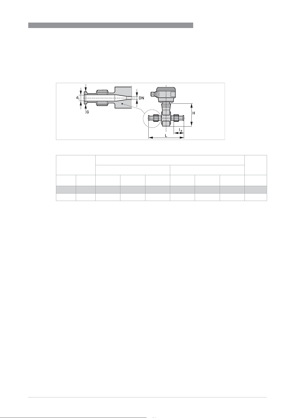
DIN 11850 (row 2 or DIN 11866 row A)
DIN 11850 (row 2 or DIN 11866 row A)
DIN 11850 (row 2 or DIN 11866 row A)DIN 11850 (row 2 or DIN 11866 row A)
DN2.5...10 screwed adapter with DN10 process connections / DN15 screwed adapter
Nominal size Dimensions [mm] Approx.
TECHNICAL DATA
Adapter Flowmeter
6
weight
DN PN d
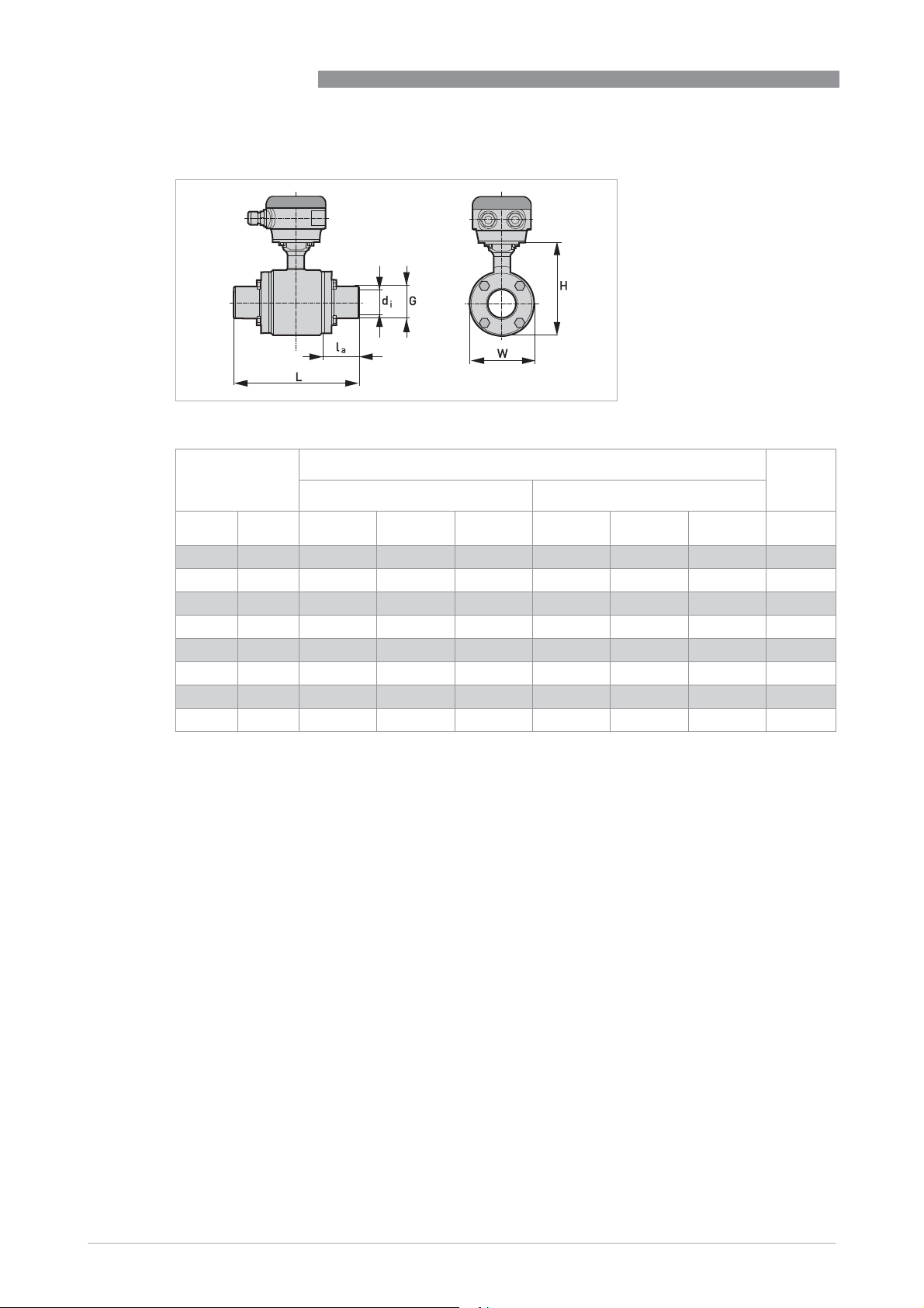
2.5...10 40 10 13 32 180 120 44 1.5
15 40 16 19 32 180 120 44 1.5
i
G l
a
L H W [kg]
www.krohne.com02/2019 - 4001723706 - HB OPTIFLUX 6000 R07 en
33
Page 34
6
TECHNICAL DATA
DN25...150 bolted adapter
Nominal size Dimensions [mm] Approx.
OPTIFLUX 6000
weight
Adapter Flowmeter
DN PN d
25 40 26 29 20.6 132.6 128 89 3
40 40 38 41 61.3 220 153 114 5.3
50 25 50 53 61.3 220 153 114 6.8
65 25 66 70 41.8 220 180 141 10.9
80 25 81 85 66.8 280 191 152 11.2
100 16 100 104 59.3 280 242 203 18.4
125 10 125 129 66.3 319 258 219 29.5
150 10 150 154 64.3 325 293 254 44.3
i
G l
a
L H W [kg]
34
www.krohne.com 02/2019 - 4001723706 - HB OPTIFLUX 6000 R07 en
Page 35
OPTIFLUX 6000
DIN 11851
DIN 11851
DIN 11851 DIN 11851
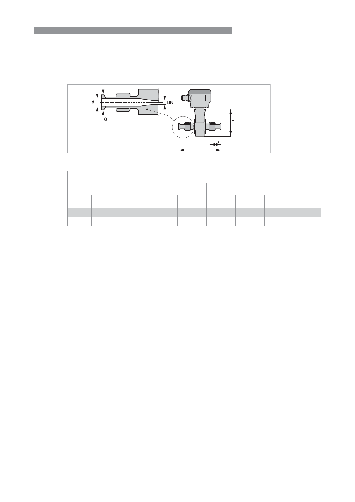
DN2.5...10 screwed adapter with DN10 process connections / DN15 screwed adapter
TECHNICAL DATA
6
Nominal size Dimensions [mm] Approx.
weight
Adapter Flowmeter
DN PN d
2.5...10 40 10 Rd 28 x 1/8" 53.1 214 142 44 1.5
15 40 16 Rd 34 x 1/8" 53.1 214 142 44 1.5
i
G l
a
L H W [kg]
www.krohne.com02/2019 - 4001723706 - HB OPTIFLUX 6000 R07 en
35
Page 36
6
TECHNICAL DATA
DIN 11851
DIN 11851
DIN 11851DIN 11851
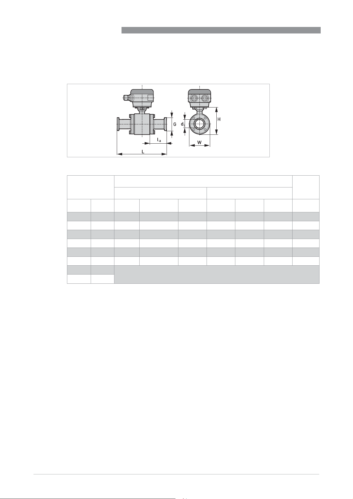
DN25...150 bolted adapter
Nominal size Dimensions [mm] Approx.
OPTIFLUX 6000
weight
Adapter Flowmeter
DN PN d
25 40 26 Rd 52 x 1/6" 49.3 190 128 89 3.2
40 40 38 Rd 65 x 1/6" 91.3 280 153 114 5.5
50 25 50 Rd 78 x 1/6" 93.3 284 153 114 5.3
65 25 66 Rd 95 x 1/6" 77.8 292 180 141 10
80 25 81 Rd 110 x 1/4" 107.8 362 191 152 12.5
100 16 100 Rd 130 x 1/4" 109.3 380 242 203 21.8
125 10 On request
150 10
i
G l
a
L H W [kg]
36
www.krohne.com 02/2019 - 4001723706 - HB OPTIFLUX 6000 R07 en
Page 37
OPTIFLUX 6000
DIN 11864-2A
DIN 11864-2A
DIN 11864-2ADIN 11864-2A
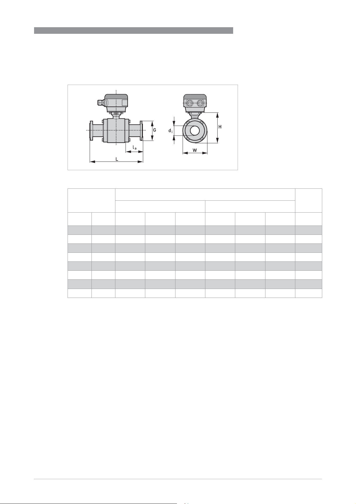
DN25...150 bolted adapter
TECHNICAL DATA
6
Nominal size Dimensions [mm] Approx.
weight
Adapter Flowmeter
DN PN d
25 40 26 70 45.8 183 128 89 4.4
40 25 38 82 83.3 264 153 114 7.5
50 25 50 94 83.3 264 153 114 9
65 25 66 113 63.8 264 180 141 14.5
80 25 81 133 122.8 392 191 152 18.6
100 16 100 159 115.3 392 242 203 28.2
125 10 125 183 121 429 259 219 35
150 10 150 213 127 450 294 254 52
i
G l
a
L H W [kg]
www.krohne.com02/2019 - 4001723706 - HB OPTIFLUX 6000 R07 en
37
Page 38
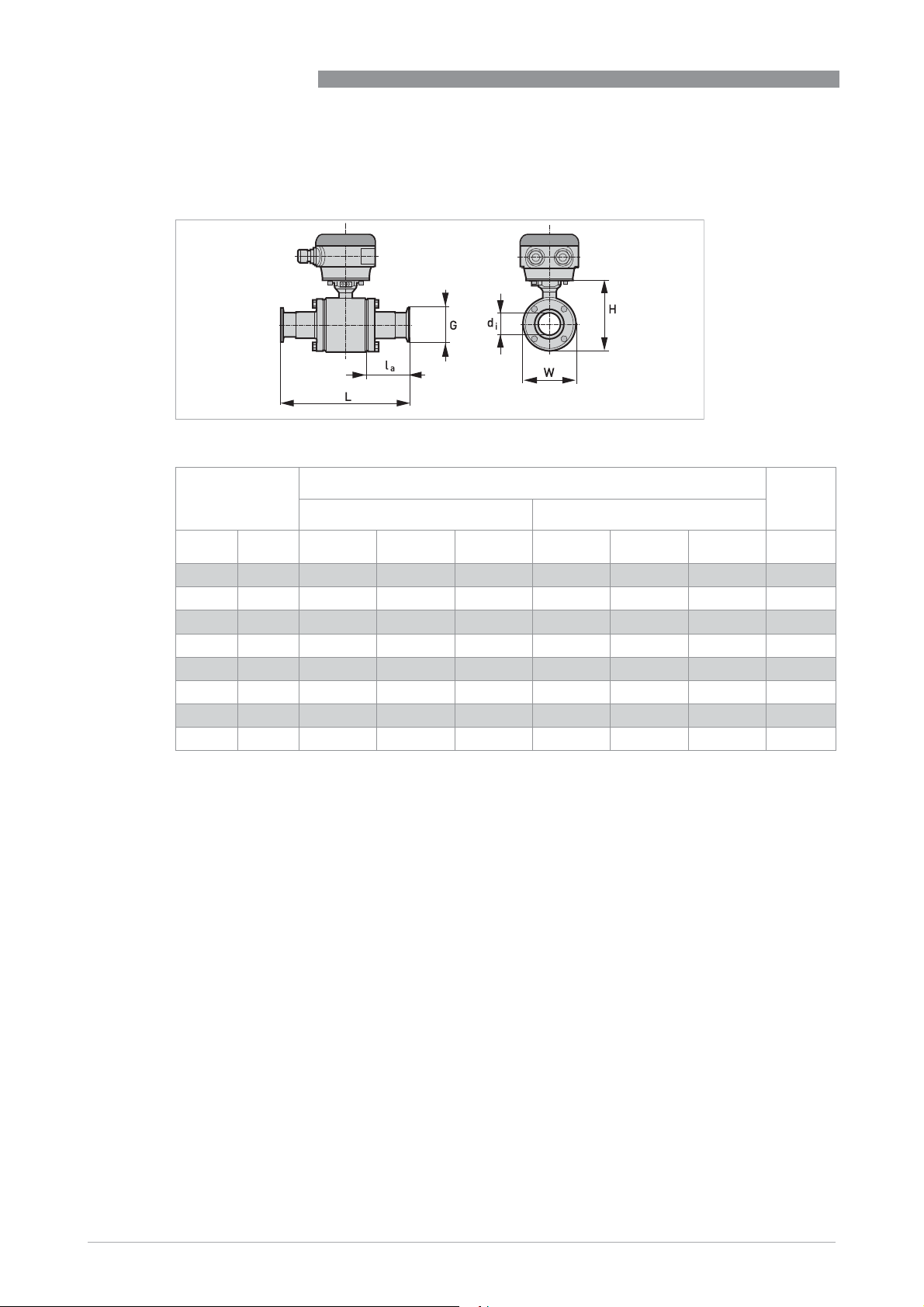
6
TECHNICAL DATA
DIN 32676
DIN 32676
DIN 32676DIN 32676
DN25...150 bolted adapter
Nominal size Dimensions [mm] Approx.
OPTIFLUX 6000
weight
Adapter Flowmeter
DN PN d
25 16 26 50.5 41.8 175 128 89 3.2
40 16 38 50.5 80.8 259 153 114 5.5
50 16 50 64 80.8 259 153 114 5.3
65 16 66 91 67.8 272 180 141 10
80 16 81 106 92.8 332 191 152 12.5
100 16 100 119 85.3 332 242 203 21.8
125 16 125 155 90 366 259 219 30
150 16 150 213 127 450 294 254 45
i
G l
a
L H W [kg]
38
www.krohne.com 02/2019 - 4001723706 - HB OPTIFLUX 6000 R07 en
Page 39
OPTIFLUX 6000
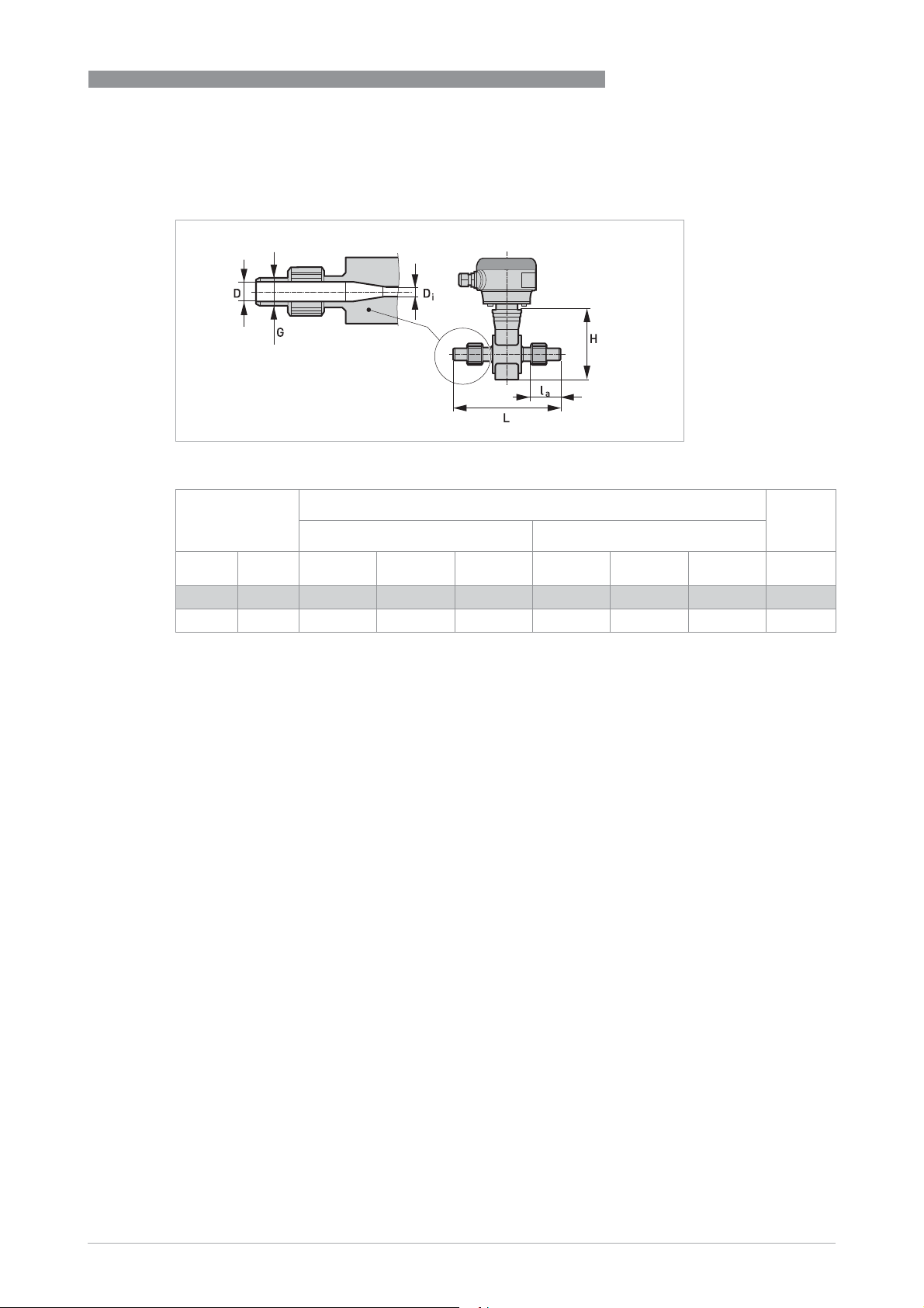
ISO 2037
ISO 2037
ISO 2037 ISO 2037
DN2.5...10 screwed adapter with DN10 process connections / DN17.2 screwed adapter
TECHNICAL DATA
6
Nominal size Dimensions [mm] Approx.
weights
Adapter Flowmeter
DN PN d
2.5...12 40 10 15 32 180 142 44 1.5
17.2 40 16 21 32 180 142 44 1.5
i
G l
a
L H W [kg]
www.krohne.com02/2019 - 4001723706 - HB OPTIFLUX 6000 R07 en
39
Page 40
6
TECHNICAL DATA
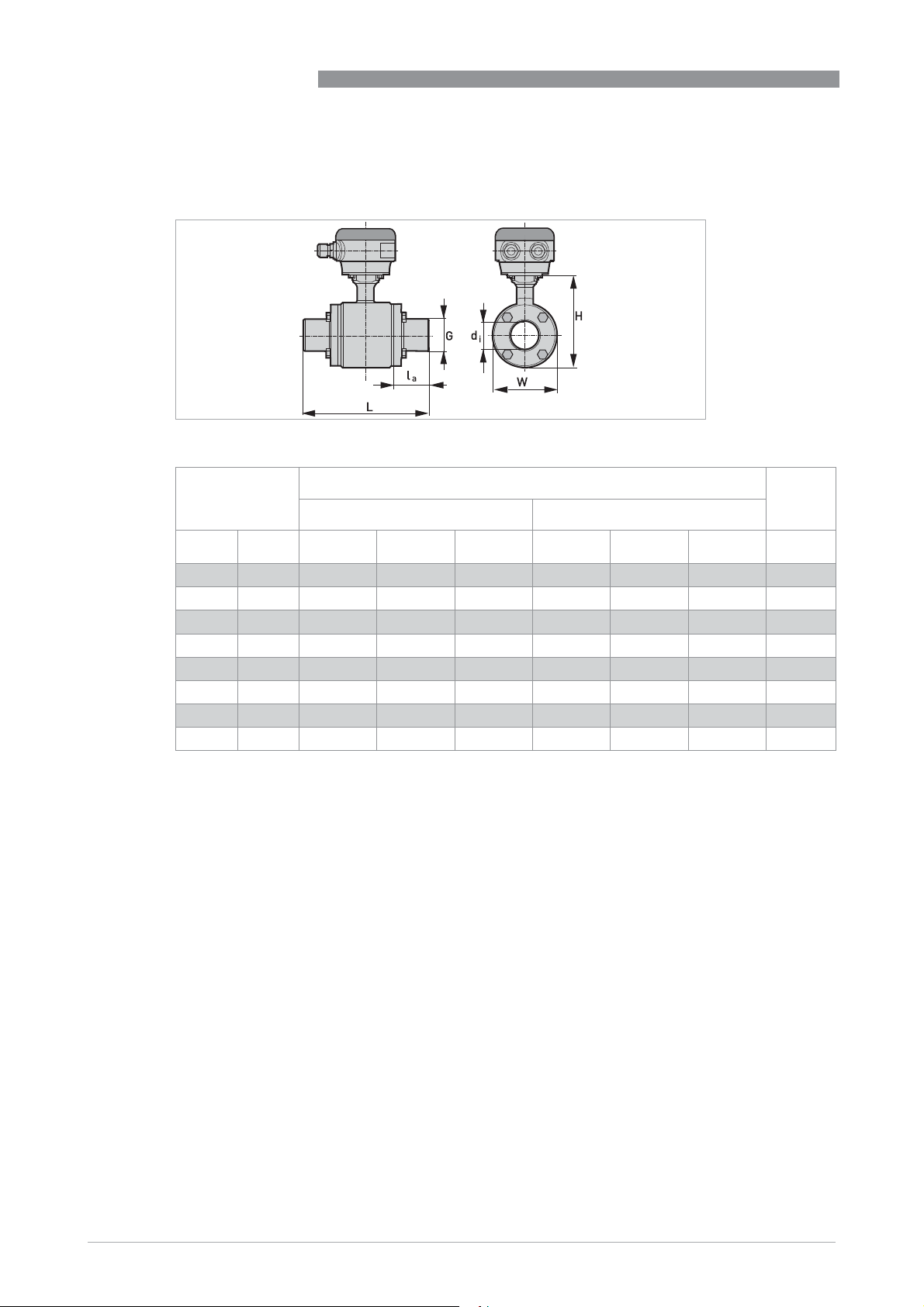
ISO 2037
ISO 2037
ISO 2037 ISO 2037
DN25...150 bolted adapter
Nominal size Dimensions [mm] Approx.
OPTIFLUX 6000
weights
Adapter Flowmeter
DN PN d
25 40 22.6 31 20.6 132.6 128 89 3
38 40 38 43 61.3 220 153 114 5.3
51 25 49 55 61.3 220 153 114 5
63.5 25 60.3 71 41.8 220 180 141 9
76.1 25 72.9 86 66.8 280 191 152 10.8
101.6 16 97.6 105 59.3 280 242 203 18.4
114.3 10 110.3 130 66.3 319 258 219 29.5
139.7 10 135.7 156 64.3 325 293 254 44.3
i
G l
a
L H W [kg]
40
www.krohne.com 02/2019 - 4001723706 - HB OPTIFLUX 6000 R07 en
Page 41
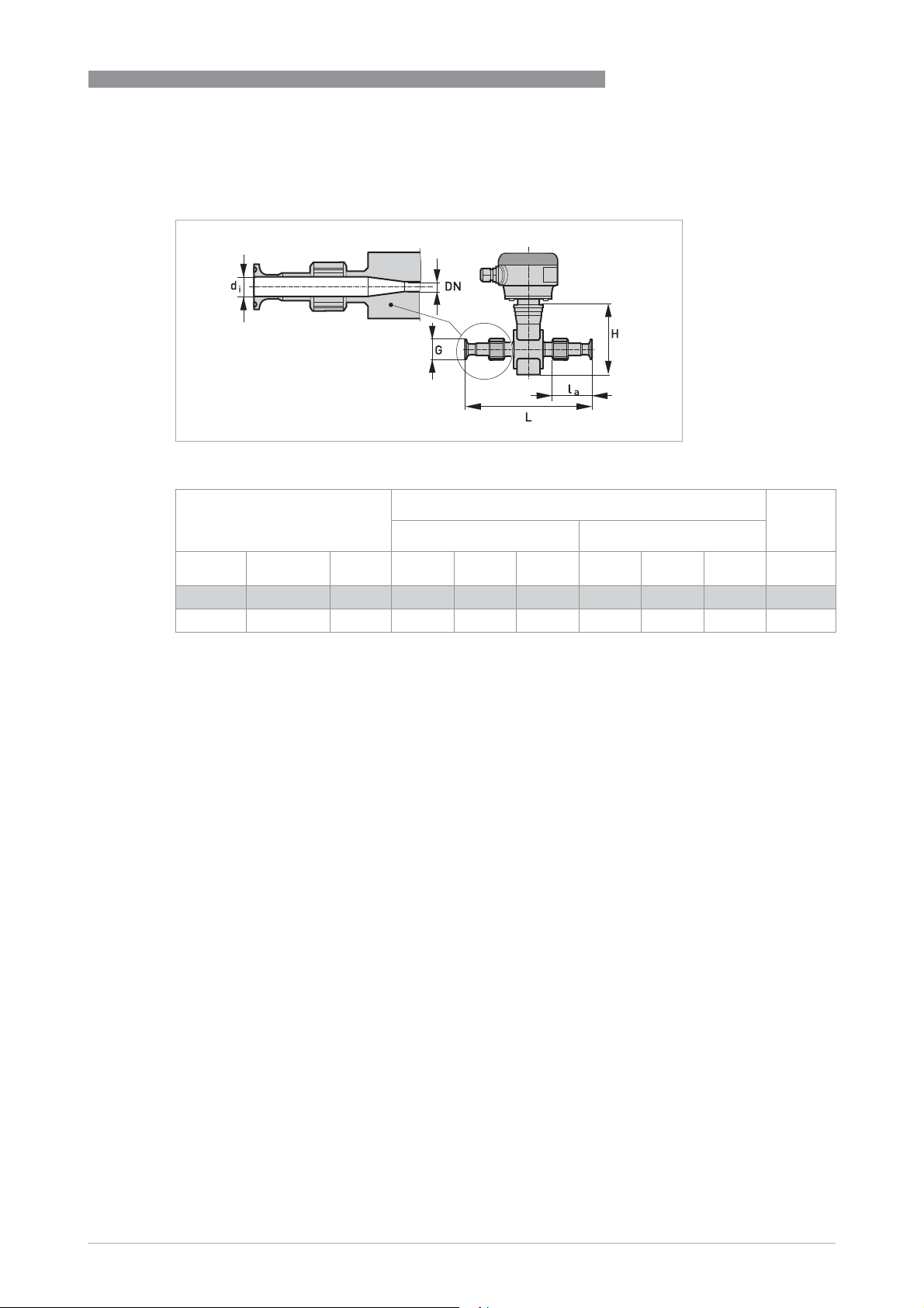
OPTIFLUX 6000
ISO 2852
ISO 2852
ISO 2852ISO 2852
DN2.5...10 screwed adapter with DN10 process connections / DN17.2 screwed adapter
TECHNICAL DATA
6
Nominal size Dimensions [mm] Approx.
weight
Adapter Flowmeter
DN [Inch] PN d
2.5...10 1/10"...3/8" 16 10 34 51.6 219 142 44 1.8
17.2 1/2" 16 16 34 51.6 219 142 44 1.8
i
G l
a
L H W [kg]
www.krohne.com02/2019 - 4001723706 - HB OPTIFLUX 6000 R07 en
41
Page 42
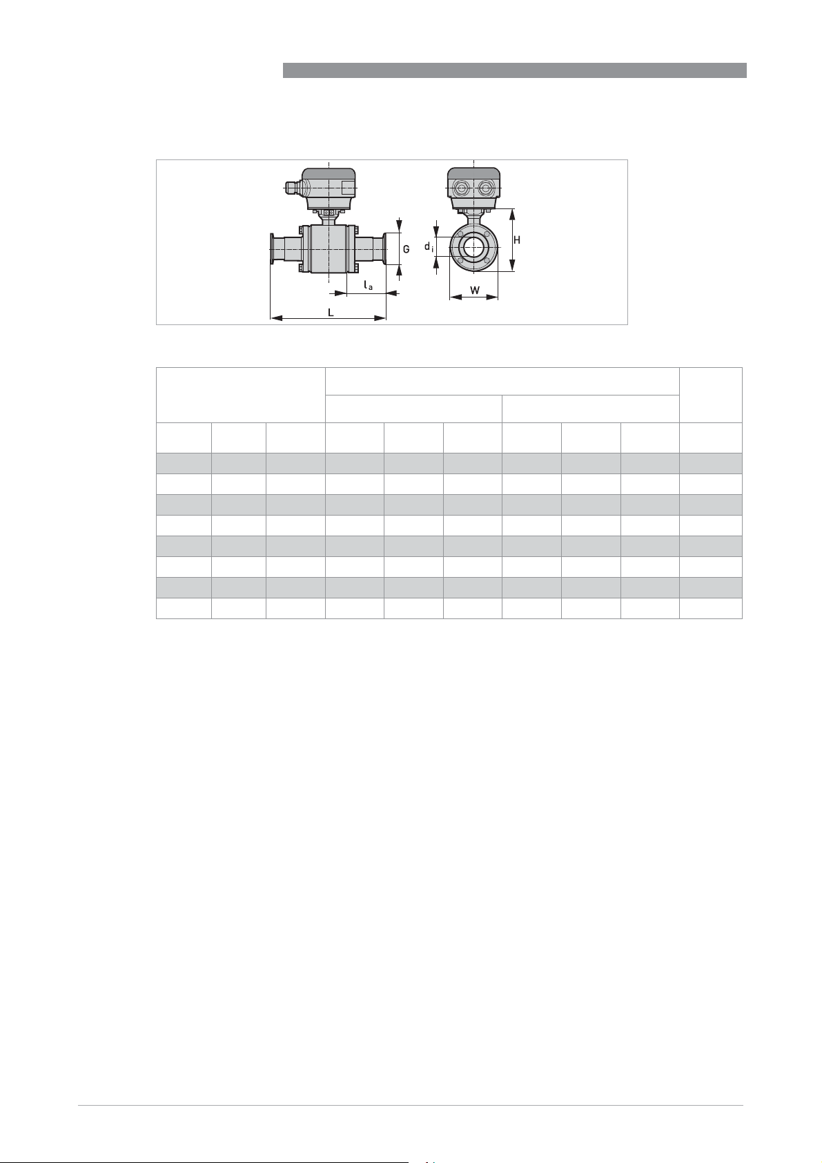
6
TECHNICAL DATA
DN25...150 bolted adapter
Nominal size Dimensions [mm] Approx.
OPTIFLUX 6000
weight
Adapter Flowmeter
DN [Inch] PN d
25 1" 16 22.6 50,5 41.8 175 128 89 3.3
38 1.5" 16 35.6 50,5 87.8 273 153 114 5.4
50 2" 16 48.6 64 87.8 273 153 114 5.2
63.5 2.5" 10 60.3 77.5 68.3 273 180 141 9.5
76.1 3" 10 72.9 91 93.3 333 191 152 11.2
101.6 4" 8 97.6 119 85.8 333 242 203 19.1
114.3 5" 5 110.3 211 90 366 259 219 30
139.7 6" 5 135.7 246 90 376 294 254 45
i
G l
a
L H W [kg]
42
www.krohne.com 02/2019 - 4001723706 - HB OPTIFLUX 6000 R07 en
Page 43
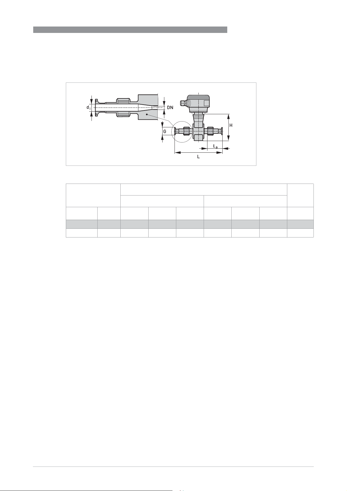
OPTIFLUX 6000
Tri Clamp
Tri Clamp
Tri ClampTri Clamp
DN1/10...1/2" screwed adapter
TECHNICAL DATA
6
Nominal size Dimensions [inch] Approx.
weight
Adapter Flowmeter
DN PN d
1/10"...3/8" 20 0.37 0.98 1.97 8.5 5.59 1.73 1.5
1/2" 20 0.62 0.98 1.97 8.5 5.59 1.73 1.5
i
G l
a
L H W [kg]
www.krohne.com02/2019 - 4001723706 - HB OPTIFLUX 6000 R07 en
43
Page 44
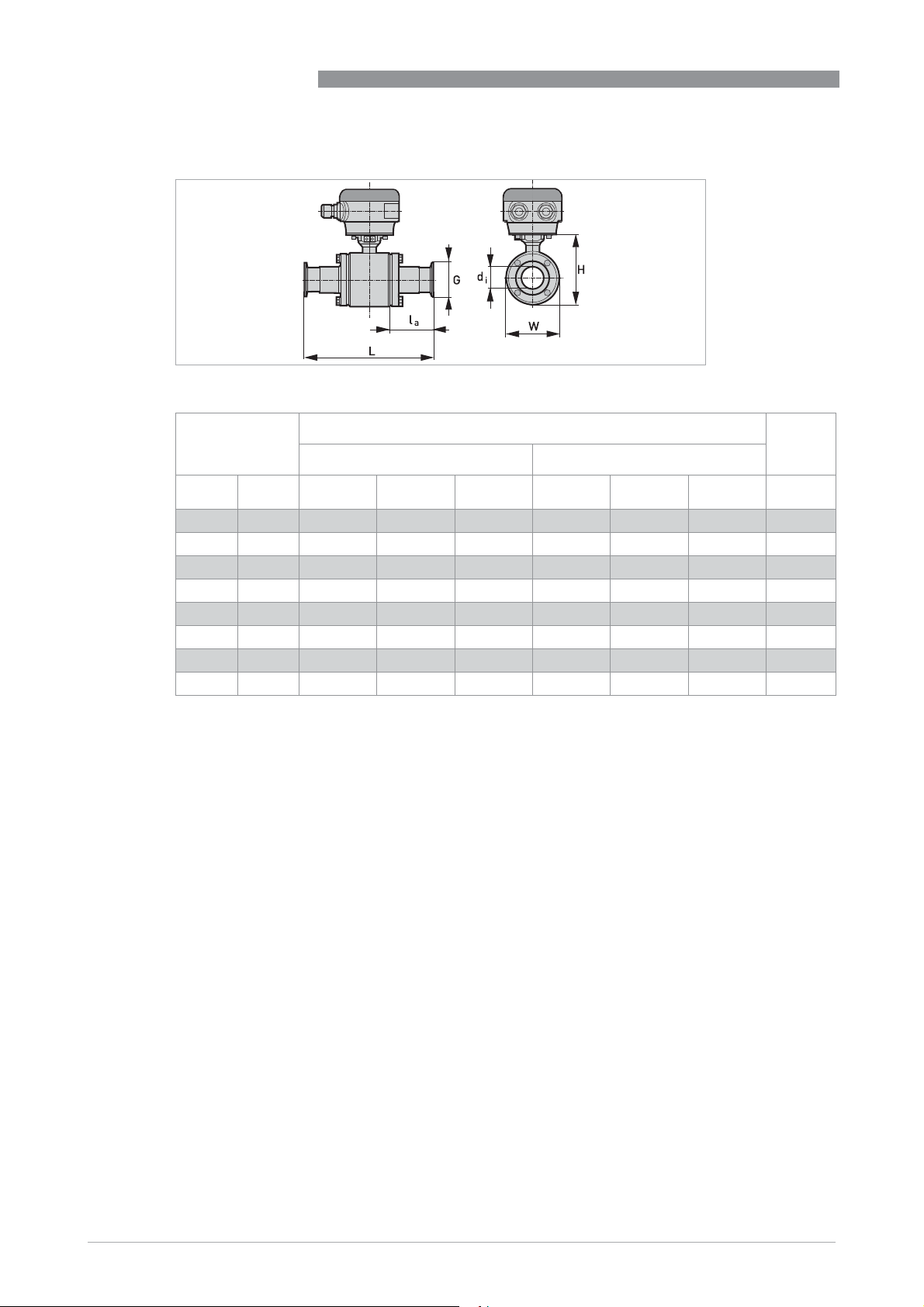
6
TECHNICAL DATA
DN1...6" bolted adapter
Nominal size Dimensions [inch] Approx.
OPTIFLUX 6000
weight
Adapter Flowmeter
DN PN d
1" 20 0.85 1.98 1.02 5.64 5.04 3.5 3.2
1½" 20 1.35 1.98 3.46 10.75 6.02 4.49 5.5
2" 20 1.85 2.52 3.46 10.75 6.02 4.49 5.3
2½" 20 2.35 3.05 2.69 10.75 7.09 5.55 10
3" 20 2.85 3.54 3.68 13.11 7.52 5.98 12.5
4" 12 3.83 4.68 3.38 13.11 9.53 7.99 21.8
5" '- 4.78 5.69 3.54 14.43 10.20 8.62 30
6" '- 5.78 6.57 3.62 14.80 11.57 10.00 45
i
G l
a
L H W [kg]
44
www.krohne.com 02/2019 - 4001723706 - HB OPTIFLUX 6000 R07 en
Page 45
OPTIFLUX 6000
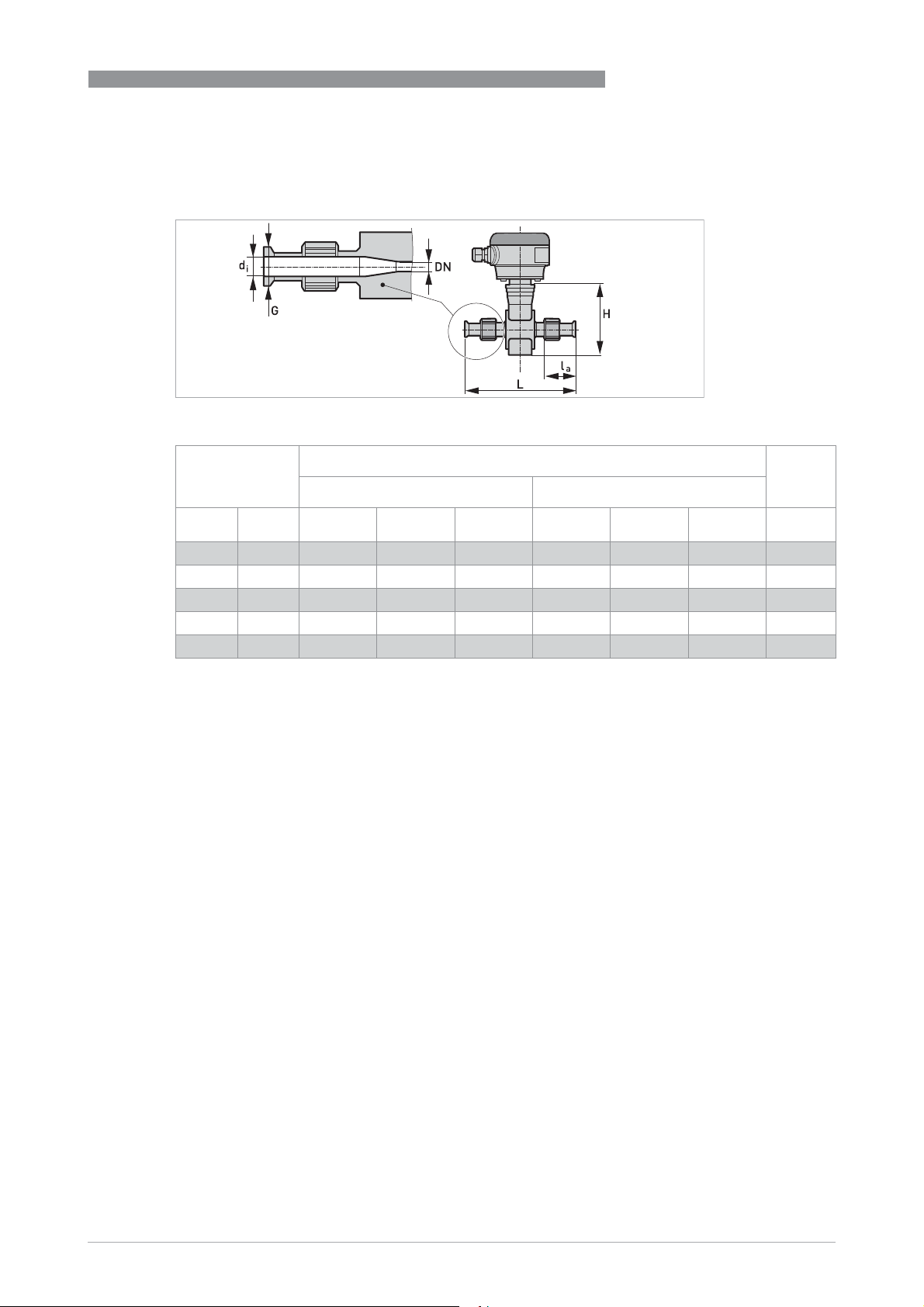
SMS 1146 Adapter
SMS 1146 Adapter
SMS 1146 AdapterSMS 1146 Adapter
DN2.5...10 screwed adapter with DN10 process connections / DN15 screwed adapter
TECHNICAL DATA
6
Nominal size Dimensions [mm] Approx.
weight
Adapter Flowmeter
DN PN d
2.5 39 10 Rd 40-6 53 226 128 44 2
4 39 10 Rd 40-6 53 226 128 44 2
6 39 10 Rd 40-6 53 226 128 44 2
10 6 10 Rd 40-6 53 226 128 44 2
15 6 10 Rd 40-6 53 226 128 44 2
i
G l
a
L H W [kg]
www.krohne.com02/2019 - 4001723706 - HB OPTIFLUX 6000 R07 en
45
Page 46
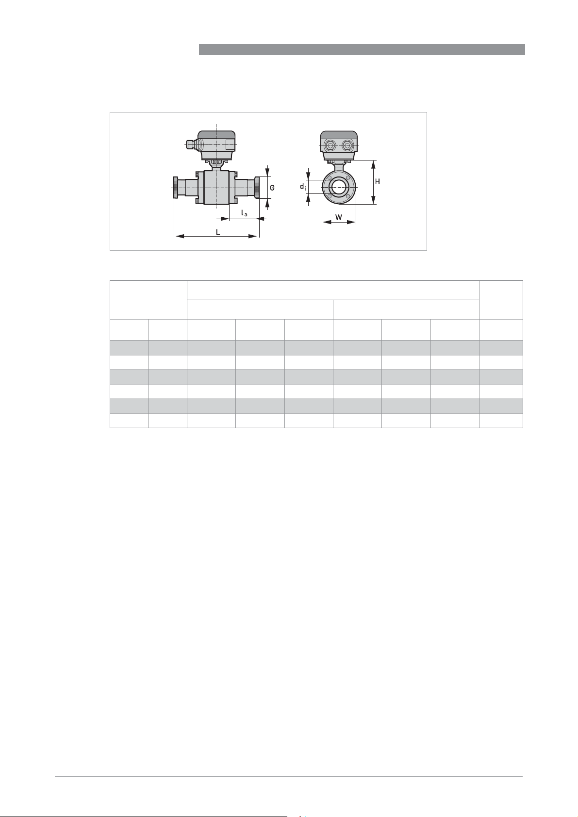
6
TECHNICAL DATA
DN25...100 bolted adapter
Nominal size Dimensions [mm] Approx.
OPTIFLUX 6000
weight
Adapter Flowmeter
DN PN d
25 6 22.6 Rd 40-6 28.1 147.6 128 89 3.2
38 6 35.5 Rd 60-6 54 262 153 114 5.7
51 6 48.6 Rd 70-6 84.3 266 153 114 5.4
63.5 6 60.3 Rd 85-6 69.8 276 180 141 9.9
76 6 72.9 Rd 98-6 99.8 346 191 152 12.1
100 6 97.6 Rd 132-6 44 336 242 203 21.9
i
G l
a
L H W [kg]
46
www.krohne.com 02/2019 - 4001723706 - HB OPTIFLUX 6000 R07 en
Page 47

OPTIFLUX 6000
NOTES
7
www.krohne.com02/2019 - 4001723706 - HB OPTIFLUX 6000 R07 en
47
Page 48

KROHNE – Process instrumentation and measurement solutions
•
Flow
•
Level
•
Temperature
•
Pressure
•
Process Analysis
•
Services
Head Office KROHNE Messtechnik GmbH
Ludwig-Krohne-Str. 5
47058 Duisburg (Germany)
Tel.: +49 203 301 0
Fax: +49 203 301 10389
[email protected]
© KROHNE 02/2019 - 4001723706 - HB OPTIFLUX 6000 R07 en - Subject to change without notice.
The current list of all KROHNE contacts and addresses can be found at:
www.krohne.com
 Loading...