

KROHNE OPTISWIRL 4200 Specifications
Technical Datasheet
Technical Datasheet
OPTISWIRL 4200
OPTISWIRL 4200
OPTISWIRL 4200OPTISWIRL 4200
Technical DatasheetTechnical Datasheet
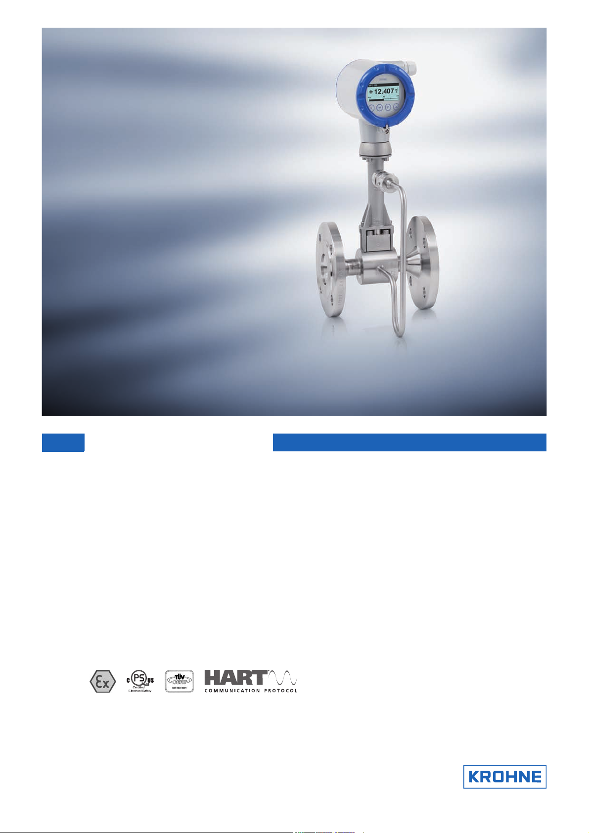
Vortex flowmeter
•
Integrated pressure and temperature compensation
•
Gross and net heat measurement for hot water and steam
•
Stable measurements even under demanding process conditions with advanced
technology for signal filtering (AVFD)
© KROHNE 08/2016 - 4003952204 - TD OPTISWIRL 4200 R04 en

CONTENTS
OPTISWIRL 4200
1 Product features 3
1.1 The all-in-one solution..................................................................................................... 3
1.2 Options and variants......................................................................................................... 5
1.3 Devices with integrated nominal diameter reduction ..................................................... 8
1.4 Functional principle.......................................................................................................... 9
2 Technical data 10
2.1 Technical data................................................................................................................. 10
2.2 Dimensions and weights ................................................................................................ 15
2.2.1 Flange versions..................................................................................................................... 15
2.2.2 Sandwich version .................................................................................................................. 22
2.2.3 Dimensions of remote version.............................................................................................. 24
2.3 Flow tables ..................................................................................................................... 25
3 Installation 28
3.1 Intended use ................................................................................................................... 28
3.2 Installation conditions ....................................................................................................30
3.2.1 Prohibited installation when measuring liquids .................................................................. 31
3.2.2 Prohibited installation when measuring steam and gases.................................................. 32
3.2.3 Pipelines with control valve .................................................................................................. 32
3.2.4 Preferred mounting position ................................................................................................ 33
3.3 Minimum inlet sections.................................................................................................. 34
3.4 Minimum outlet sections................................................................................................ 35
3.5 Flow straightener ........................................................................................................... 35
3.6 Heat insulation................................................................................................................ 36
4 Electrical connections 37
4.1 Connecting the signal converter .................................................................................... 37
4.2 Electrical connections .................................................................................................... 38
4.3 Connection of remote version ........................................................................................ 38
5 Order form 40
6 Notes 41
2
www.krohne.com 08/2016 - 4003952204 - TD OPTISWIRL 4200 R04 en
OPTISWIRL 4200
1.1 The all-in-one solution
Vortex flowmeters are suitable for a wide range of media. This is particularly true of the
OPTISWIRL 4200
OPTISWIRL 4200. Its capability to master even fluctuating pressures and temperatures turns it
OPTISWIRL 4200OPTISWIRL 4200
into an ideal all-rounder for the measurement of energy carriers in auxiliary and supply
processes.
PRODUCT FEATURES
1
Already the basic version of the OPTISWIRL 4200
for saturated steam applications. With the optional pressure sensor the flowmeter has an
integrated density compensation available, which even allows an exact measurement of gases
and superheated steam with varying process conditions. The additional integrated gross and net
heat measurement makes this flowmeter to be a reliable partner for advanced energy
management systems.
With the innovative AVFD (Advanced Vortex Frequency Detection) the OPTISWIRL 4200
with an up-to-date signal filter. It analyses the measured signal and eliminates interferences
and perturbations. Thereby, stable measurements can even be realised under demanding
process conditions.
This vortex flowmeter was designed for the safety-related applications from the very beginning.
It was developed according to the standard IEC 61508 edition 2. The certification is effected
within the scope of a full assessment by TUEV Sued. Thereby the flowmeter can be used for
continuous volume flow measurement in safety-related applications with classification SIL 2.
OPTISWIRL 4200 is equipped with a temperature compensation
OPTISWIRL 4200OPTISWIRL 4200
OPTISWIRL 4200 is fitted
OPTISWIRL 4200OPTISWIRL 4200
www.krohne.com08/2016 - 4003952204 - TD OPTISWIRL 4200 R04 en
3

1
PRODUCT FEATURES
Highlights
• Development according to IEC 61508, edition 2
• Advanced technology for signal filtering - AVFD (Advanced Vortex Frequency Detection)
• Integrated pressure and temperature compensation
• Temperature compensation for saturated steam included as standard
• Integrated gross and net heat calculation for steam and hot water
• Comprehensive communication options
• Remote version with field housing converter with cable length up to 50 m / 164 ft
• Integrated reduction of nominal size
• Measurement of conductive and non-conductive liquids, gases and steam
Industries
• Chemicals
• Oil & Gas
• Power plants
• Food & Beverage
• Pharmaceuticals
• Iron, Steel and Metals
• Pulp & Paper
• Water
• Automotive industry
OPTISWIRL 4200
Applications
• Measurement of saturated steam and superheated steam
• Steam boiler monitoring
• Heat metering of steam and hot water
• Measurement of consumption of industrial gases
• Measurement of consumption in compressed air systems
• Monitoring of compressor output
• Evaluation of free air delivery (FAD)
• SIP and CIP processes in the food, beverage and pharmaceutical industries
• Safety-related measurement in SIL applications (SIL 2)
4
www.krohne.com 08/2016 - 4003952204 - TD OPTISWIRL 4200 R04 en
OPTISWIRL 4200
PRODUCT FEATURES
1.2 Options and variants
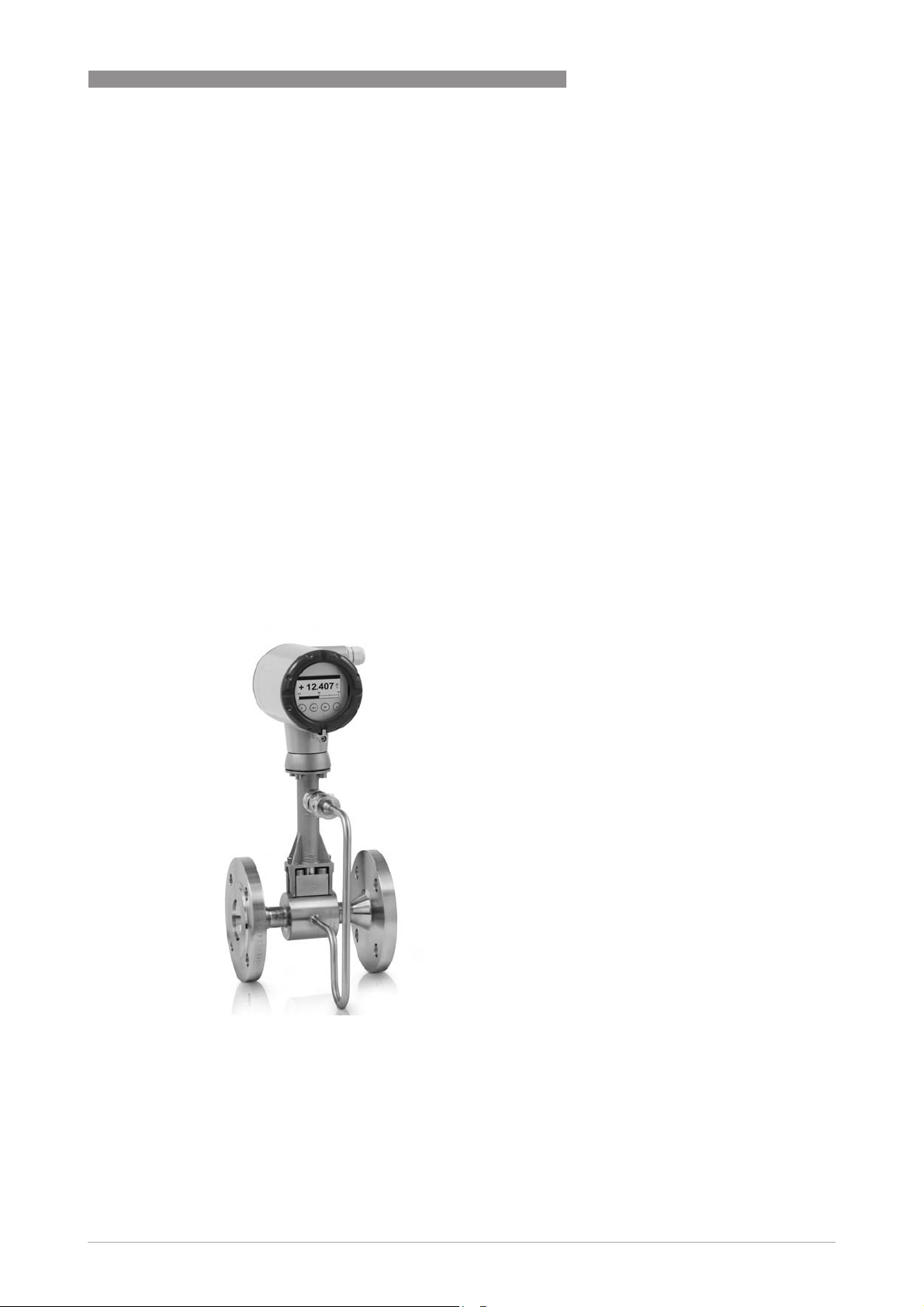
1. The universal device with temperature compensation for saturated steam integrated as
standard
The OPTISWIRL 4200 C
OPTISWIRL 4200 C as compact flowmeter in a
OPTISWIRL 4200 COPTISWIRL 4200 C
flange version is suitable for universal use in
measuring liquids, gases and vapours.
The temperature compensation for saturated steam
is integrated as standard, thus enabling direct
compensation of the density; the mass and energy
can also be measured.
The advanced signal filter technology AVFD
(Advanced Vortex Frequency Detection)
complements the high accurate measurement.
1
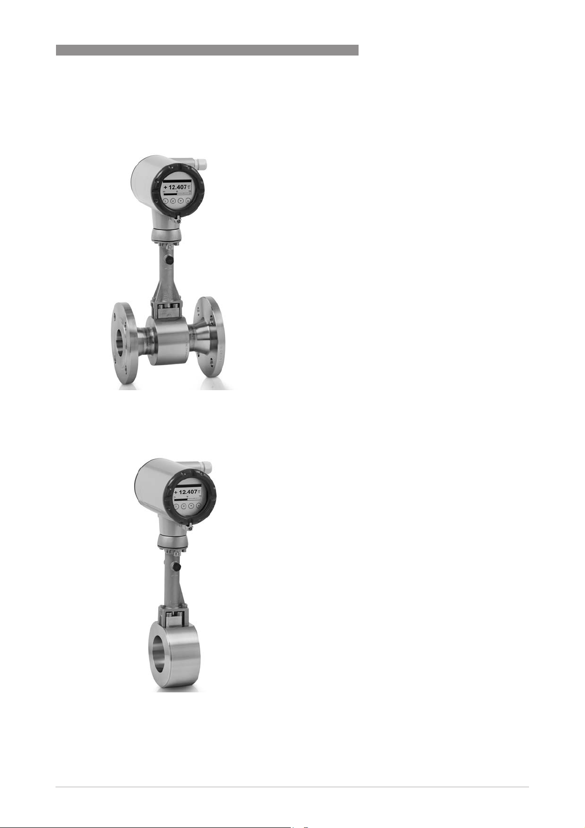
2. The easy to install sandwich version with optimised centering rings
The OPTISWIRL 4200 C
OPTISWIRL 4200 C as a compact flowmeter in a
OPTISWIRL 4200 COPTISWIRL 4200 C
sandwich version is suitable for universal use in the
measurement of liquids, gases and vapours.
The temperature compensation for saturated steam
is integrated as standard.
The flowmeter is provided with additional optimised
centering rings. The vortex flowmeter can be aligned
centrically by turning the centering rings,
eliminating any offset between the flowmeter and
the pipeline.
www.krohne.com08/2016 - 4003952204 - TD OPTISWIRL 4200 R04 en
5
1
PRODUCT FEATURES
OPTISWIRL 4200
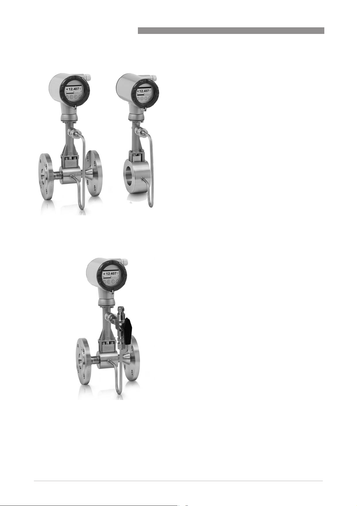
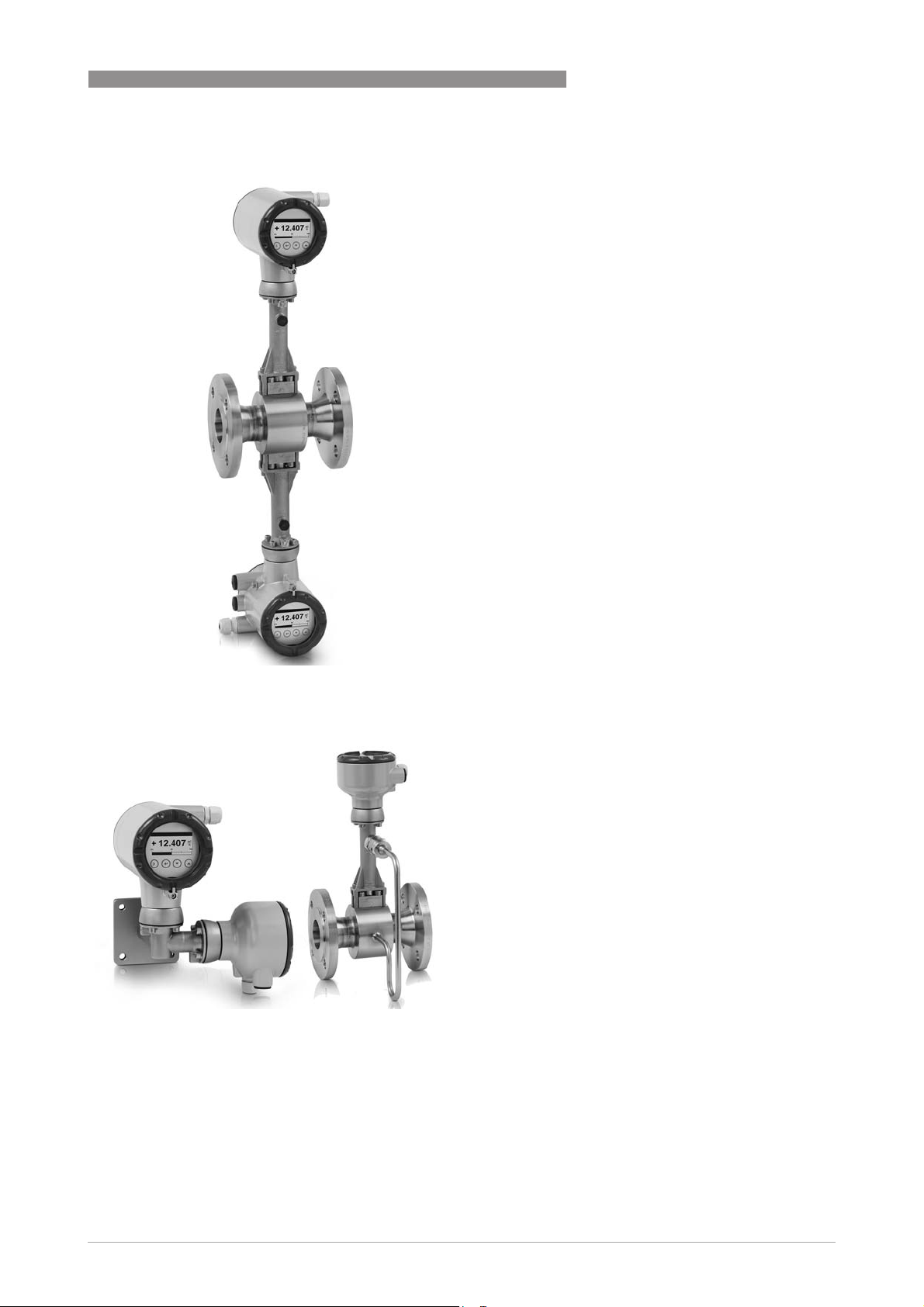
3. The one-of-a-kind 2-wire device with integrated pressure and temperature compensation
The OPTISWIRL 4200
OPTISWIRL 4200 as a flange or sandwich
OPTISWIRL 4200OPTISWIRL 4200
flowmeter is optinally available with integrated
pressure and temperature compensation for gases,
wet gases, gas mixtures or steam.
The advantage of this unique design couldn’t be
clearer:
• No additional cost-intensive installation of
pressure and temperature sensors
• No additional cabling work
• No faulty measurement results, because pressure,
temperature and volume flow can be read at a
single point
• Direct measurement of mass and/or energy
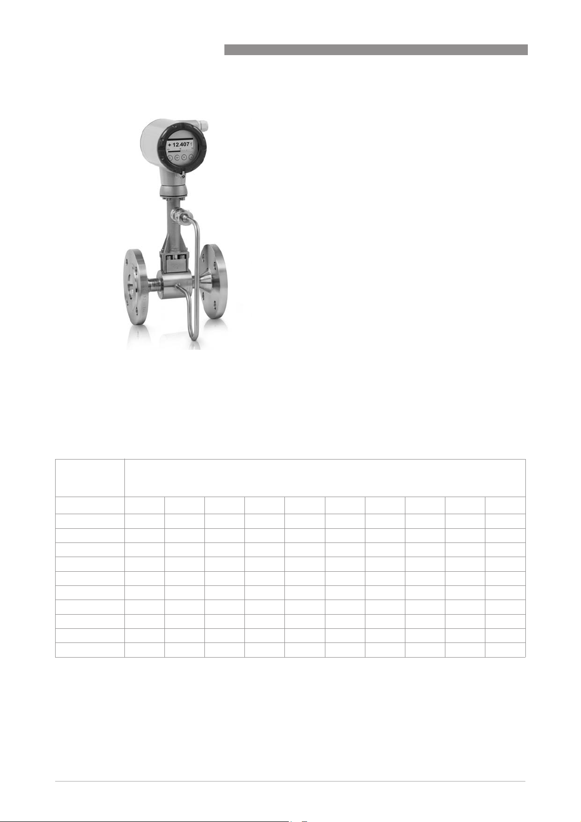
4. Vortex flowmeter with shut-off valve for the pressure measurement
As an option, the OPTISWIRL 4200
with a shut-off valve to allow the pressure sensor to
be exchanged without interrupting the process.
What is more, the pressure sensor can be shut off
for the purpose of pressure or leak testing of the
pipeline.
Using the built-in two-way valve, the pressure
sensor can also be calibrated and tested at a later
time.
OPTISWIRL 4200 can be supplied
OPTISWIRL 4200OPTISWIRL 4200
6
www.krohne.com 08/2016 - 4003952204 - TD OPTISWIRL 4200 R04 en
OPTISWIRL 4200
5. Dual measurement for twofold reliability
PRODUCT FEATURES
The OPTISWIRL 4200
OPTISWIRL 4200 is optionally available as a dual
OPTISWIRL 4200OPTISWIRL 4200
version.
This is a genuine redundant system with two
independent flow sensors and two signal converters.
This provides twofold functional reliability and
availability of the measurement.
This variant is ideally suited for measurements in
multi-product pipelines. In such pipelines, two
different products are moved through one after the
other.
One signal converter can be programmed for one
product, and the other signal converter for the other
product.
1
6. The OPTISWIRL 4200 F as remote version
The OPTISWIRL 4200
OPTISWIRL 4200 is also available as a remote
OPTISWIRL 4200OPTISWIRL 4200
version with field housing converter.
This feature allows separating the signal converter
from the flow sensor up to a distance of 50 m /
164 ft, in case the flow sensor is mounted in
inaccessible areas.
The remote mounted signal converter allows easy
operation and reading of values at eye level.
Additionally to the flow rates, measurements of the
integrated pressure and temperature sensors can
be displayed.
www.krohne.com08/2016 - 4003952204 - TD OPTISWIRL 4200 R04 en
7
1
PRODUCT FEATURES
7. OPTISWIRL 4200 F1R / F2R with integrated nominal diameter reduction
The OPTISWIRL 4200 F1R / F2R
OPTISWIRL 4200 F1R / F2R with integrated
OPTISWIRL 4200 F1R / F2ROPTISWIRL 4200 F1R / F2R
nominal diameter reduction up to two nominal
diameter sizes assures best results in accuracy and
optimal measuring ranges even in pipelines with
large diameters, which have been designed for a low
pressure loss.
By forgoing complex pipeline reduction installations,
space and cost saving installations can be realized.
At the same time the number of potential leakages is
reduced to a minimum.
OPTISWIRL 4200
1.3 Devices with integrated nominal diameter reduction
The device versions F1R and F2R offer an integrated nominal diameter reduction up to two
nominal diameter sizes to assure best results in accuracy and optimum measuring ranges; even
in pipelines with large diameters, which have been designed for a low pressure loss.
Nominal
diameter of flow
sensor
DN15 StV
DN25 - StV
DN40 --StV
DN50 ---StV
DN80 ----StV
DN100 -----StV
DN150 ------StV
DN200 -------StV
DN250 --------StV
DN300 ---------StV
1 Standard version
Nominal size of process connections
DN15 DN25 DN40 DN50 DN80 DN100 DN150 DN200 DN250 DN300
1
F1RF2R-------
1
F1RF2R------
1
F1RF2R-----
1
F1RF2R----
1
F1RF2R---
1
F1R F2R - -
1
F1R F2R -
1
F1R F2R
1
F1R
1
8
www.krohne.com 08/2016 - 4003952204 - TD OPTISWIRL 4200 R04 en
OPTISWIRL 4200
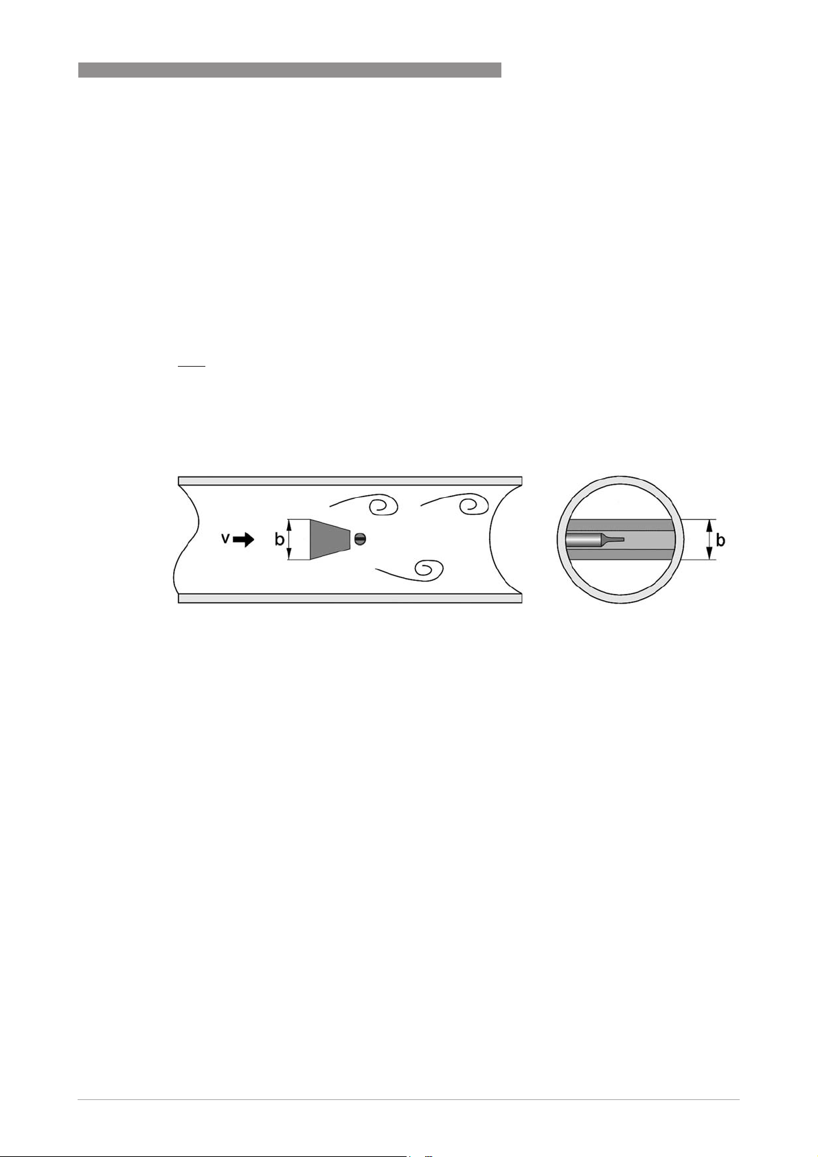
1.4 Functional principle
Vortex flowmeters are used to measure the flow of gases, vapours and liquids at completely
filled pipes.
The measuring principle is based on the Karman vortex street. The measuring tube contains a
bluff body at which vortex shedding occurs and which is detected by a sensor unit located behind.
The frequency ffff of the vortex shedding is proportional to the flow velocity vvvv. The non-dimensional
Stouhal number SSSS describes the relationship between vortex frequency ffff, width bbbb of the bluff
body and the average flow velocity vvvv:
S.v
f
=
b
The vortex frequency is recorded at the flow sensor and evaluated at the signal converter.
PRODUCT FEATURES
1
Figure 1-1: Functional principle
www.krohne.com08/2016 - 4003952204 - TD OPTISWIRL 4200 R04 en
9

2
TECHNICAL DATA
2.1 Technical data
•
The following data is provided for general applications. If you require data that is more
relevant to your specific application, please contact us or your local sales office.
•
Additional information (certificates, special tools, software,...) and complete product
documentation can be downloaded free of charge from the website (Downloadcenter).
Measuring system
Application range Flow measurement of liquids, gases and vapours
Function / Measuring
principle
Measurement
Primary measured value Number of separated vortices
Secondary measured value Operating and standard volume flow and mass flow
Signal converter
Versions Compact
Karman vortex street
Remote version (in preparation)
Cable length: ≤ 50 m / 164 ft
OPTISWIRL 4200
Flow sensor
Standard Flange version (with integrated temperature measurement), flow sensor: F
Sandwich version (with integrated temperature measurement), flow sensor: S
Option Basic device with additional pressure measurement
Basic device with additional pressure measurement and shut-off valve for pressure
sensor
Dual measuring device in both flange and sandwich version (redundant measurement)
Dual measuring device with additional pressure measurement
Flange version with single reduction of nominal diameter, flow sensor: F1R
Flange version with double reduction of nominal diameter, flow sensor: F2R
Display and user interface
Local display Graphic display
Interface and display
languages
German, English, French; 22 further languages (in preparation)
10
www.krohne.com 08/2016 - 4003952204 - TD OPTISWIRL 4200 R04 en

OPTISWIRL 4200
TECHNICAL DATA
Measuring accuracy
Reference condition
Reference conditions Water at +20°C / +68°F
Air at +20°C / +68°F and 1.013 bara / 14.7 psia
Maximum measuring error
Volume flow
(liquid)
Volume flow
(gases and steam)
Mass flow
(gases and steam)
Mass flow
(liquid / water)
Normalised volume flow
(gas)
Repeatability
(volume flow)
1 The maximum error of measurement refers to measurement at an operating pressure >65% of the full scale value of
the applied pressure sensor.
±0.75% of measured value (Re ≥ 20000)
±2.0% of measured value (10000 < Re < 20000)
±1.0% of measured value (Re ≥ 20000) 1
±2.0% of measured value (10000 < Re < 20000) 1
±1.5% of measured value (Re ≥ 20000)
±2.5% of measured value (10000 < Re < 20000)
±1.5% of measured value (Re ≥ 20000)
±2.5% of measured value (10000 < Re < 20000)
±1.5% of measured value (Re ≥ 20000)
±2.5% of measured value (10000 < Re < 20000)
±0.1% of measured value
2
Operating conditions
Temperature
Medium temperature -40…+240°C / -40…+465°F
Ambient temperature Non-Ex: -40…+85°C / -40…+185°F
Ex: -40...+65°C / -40...+140°F
Storage temperature -40...+85°C / -40...+185°F
Pressure
Medium pressure Max. 100 bar / 1450 psi (higher pressures on request)
Ambient pressure Atmosphere
Media properties
Density Taken into consideration when sizing.
Viscosity < 10 cP
Reynold's number > 10000
Recommended flow velocities
Liquids 0.25…7m/s / 0.82…23 ft/s (optional up to 10 m/s / 32.8 ft/s taking cavitation into
Gases and steam 2.0…80 m/s / 6.6…262.5 ft/s
For further information refer to
account)
DN15: 3.0…45 m/s / 9.8…148 ft/s; DN25: 2.0…70 m/s / 6.6…230 ft/s
Intended use
on page 28.
www.krohne.com08/2016 - 4003952204 - TD OPTISWIRL 4200 R04 en
11

2
TECHNICAL DATA
OPTISWIRL 4200
Other conditions
Ingress protection Compact version: IP66/67
Remote version: signal converter housing: IP66/67; flow sensor housing: IP66/67
Installation conditions
Inlet section ≥ 15 x DN without disturbing flow, after pipe narrowing, after a single 90° bend
≥ 30 x DN after a double bend 2x90°
≥ 40 x DN after a double three-dimensional bend 2x90°
≥ 50 x DN after control valves
≥ 2 DN before flow straightener; ≥ 8 DN after flow straightener
Outlet section ≥ 5 x DN
Materials
Flow sensor and process
connections
Electronics housing Aluminium die-cast, two-layer coating (epoxy/polyester)
Pressure sensor gasket Standard: FPM
Measuring tube gasket (Pickup)
Standard: 1.4404/316L
Option: Hastelloy® C-22 on request
Option: die-cast aluminium with finish for advanced requirements
Option: FFKM
Standard: 1.4435/316L
Option: Hastelloy® C-276
Selection depends on flow sensor material / medium.
Process connections of flange version
DIN EN 1092-1 DN15...300 - PN16...100 (higher pressures on request)
ASME B16.5 ½...12" - 150…600 lb (higher pressures on request)
JIS B 2220 DN15...300 - JIS 10…20 K (higher pressures on request)
For detailed information on combination flange/pressure rating, refer to section "Dimensions and weights".
Process connections of sandwich version
DIN DN15...100 - PN100 (higher pressures on request)
ASME ½...4" - 600 lb (higher pressures on request)
JIS DN15...100 - 10…20 K (higher pressures on request)
Electrical connections
Power supply Non-Ex: 12…36 VDC
Ex: 12…30 VDC
Inputs and outputs
General All inputs and outputs are electrically isolated from one another.
Time constant The time constant corresponds to 63% of the elapsed time of a processor procedure.
0...100 seconds (rounded up to 0.1 seconds)
12
www.krohne.com 08/2016 - 4003952204 - TD OPTISWIRL 4200 R04 en

OPTISWIRL 4200
TECHNICAL DATA
Current output
Type
Output data Volume flow, mass flow, norm. volume flow, gross/net power, free air delivery, density,
Resolution 5 µA
Linearity / accuracy 0.1% (of read value)
Temperature coefficient 50 ppm/K (typically), 100 ppm/K (max.)
Error signal According to NE 43
Description of abbreviations U
Load Minimum 0 Ω; maximum RL = ((U
®
HART
4...20 mA HART® (passive)
temperature (internal sensor), pressure, vortex frequency, flow velocity
= external voltage;
ext
= load + resistance
R
L
- 12 VDC) / 22 mA)
ext
HART® protocol via passive current output
2
HART® revision HART® 7
Manufacturer ID 00069 (0x45)
Device type code 00205 (0xCD)
System requirements Load min. 250 Ω
Multidrop operation 4mA
Burst mode
Catch device
Binary output
Function Pulse, frequency, status, limit switch
Type Passive
Temperature coefficient 50 ppm/K
Residual current < 0.2 mA at 32 V (Ri = 180 kΩ)
Pulse width 0.5...2000 ms
Proximity sensor acc. to DIN EN 60947-5-6 (NAMUR sensor) or pulse output signal acc.
to VDI/VDE 2188 (category 2)
www.krohne.com08/2016 - 4003952204 - TD OPTISWIRL 4200 R04 en
13

2
TECHNICAL DATA
OPTISWIRL 4200
Pulse output
Output data Volume, mass, norm. volume, gross/net energy
Pulse rate Max. 1000 pulses/s
Power supply Non-Ex: 24 VDC as NAMUR or open < 1 mA, maximum 36 V, closed 120 mA, U < 2 V
Ex: 24 VDC as NAMUR or open < 1 mA, maximum 30 V, closed 120 mA, U < 2 V
Frequency output
Output data Volume flow, mass flow, norm. volume flow, gross/net power, free air delivery, density,
Max. frequency 1000 Hz
temperature (internal sensor or via external input), pressure, vortex frequency, flow
velocity, spec. enthalpy, spec. heat capacity, Reynolds number
Status output
Output data Status acc. to NE 107 (F, S, C), flow totalizer overflow, energy totalizer overflow, fluid
type (in steam applications)
Limit switch
Output data Volume flow, mass flow, norm. volume flow, volume, mass, norm. volume, gross/net
power, gross/net energy, free air delivery, density, temperature (internal sensor or via
external input), pressure, vortex frequency, flow velocity, spec. enthalpy, spec. heat
capacity, Reynolds number
Current input
Type 4...20 mA (passive)
Resolution 6 µA
Linearity / accuracy 0.1% (of read value)
Temperature coefficient 100 ppm/K (typically), 200 ppm/K (max.)
Voltage drop 10 V
Approvals and certificates
ATEX ATEX II2 G - Ex ia IIC T6...T2 Gb
IECEx IECEx - Ex ia IIC T6...T2 Gb
QPS (USA & Canada) QPS Ordinary Locations
ATEX II2 G - Ex d ia IIC T6...T2 Gb
ATEX II3 G - Ex nA IIC T6...T2 Gc
ATEX II2 D - Ex tb IIIC T70°C Db
IECEx - Ex d ia IIC T6...T2 Gb
IECEx - Ex nA IIC T6...T2 Gc
IECEx - Ex tb IIIC T70°C Db
QPS IS Class I Div 1
QPS XP Class I Div 1 (in preparation)
QPS NI Class I Div 2 (in preparation)
QPS DIP Class II, III Div 1 (in preparation)
14
www.krohne.com 08/2016 - 4003952204 - TD OPTISWIRL 4200 R04 en
 Loading...