

Page 1
OPTISWIRL 4070
OPTISWIRL 4070
OPTISWIRL 4070OPTISWIRL 4070
Vortex flowmeter
Handbook
Handbook
HandbookHandbook
© KROHNE 04/2016 - 4000150609 - MA OPTISWIRL 4070C R10 en
Page 2

:
IMPRINT
:::::::::::::::::::::::::::::::::::::::
All rights reserved. It is prohibited to reproduce this documentation, or any part thereof, without
the prior written authorisation of KROHNE Messtechnik GmbH.
Subject to change without notice.
Copyright 2016 by
KROHNE Messtechnik GmbH - Ludwig-Krohne-Str. 5 - 47058 Duisburg (Germany)
2
www.krohne.com 04/2016 - 4000150609 - MA OPTISWIRL 4070C R10 en
Page 3

OPTISWIRL 4070
CONTENTS
1 Safety instructions 6
1.1 Intended use ..................................................................................................................... 6
1.2 Certifications .................................................................................................................... 7
1.3 Safety instructions from the manufacturer ..................................................................... 8
1.3.1 Copyright and data protection ................................................................................................ 8
1.3.2 Disclaimer ............................................................................................................................... 8
1.3.3 Product liability and warranty ................................................................................................ 9
1.3.4 Information concerning the documentation........................................................................... 9
1.3.5 Warnings and symbols used................................................................................................. 10
1.4 Safety instructions for the operator............................................................................... 10
2 Device description 11
2.1 Scope of delivery............................................................................................................. 11
2.2 Device versions............................................................................................................... 11
2.2.1 Devices with connection flange ............................................................................................ 12
2.2.2 Sandwich version .................................................................................................................. 12
2.2.3 Devices for dual measurement and twofold reliability ........................................................ 13
2.2.4 Device version remote .......................................................................................................... 13
2.2.5 Device description................................................................................................................. 14
2.2.6 Free air delivery measurement - FAD (optional) ................................................................. 14
2.2.7 Gross heat meter .................................................................................................................. 15
2.2.8 Dual seal ............................................................................................................................... 16
2.3 Nameplate ...................................................................................................................... 17
2.4 Description code............................................................................................................. 18
3 Installation 19
3.1 General notes on installation ......................................................................................... 19
3.2 Storage ........................................................................................................................... 19
3.3 Transport ........................................................................................................................ 19
3.4 Installation conditions ....................................................................................................20
3.4.1 Prohibited installation when measuring liquids .................................................................. 21
3.4.2 Recommended installations for measurement of liquids ................................................... 22
3.4.3 Prohibited installation when measuring vapours and gases............................................... 23
3.4.4 Recommended installations for measurement of steam and gases................................... 23
3.4.5 Pipelines with control valve .................................................................................................. 24
3.4.6 Preferred mounting position ................................................................................................ 24
3.4.7 Turning the connection housing ...........................................................................................25
3.4.8 Turning the display ............................................................................................................... 26
3.4.9 Heat insulation ...................................................................................................................... 27
3.5 Inlet and outlet runs....................................................................................................... 28
3.5.1 Minimum inlet runs............................................................................................................... 28
3.5.2 Minimum outlet sections ...................................................................................................... 29
3.5.3 Flow straightener.................................................................................................................. 29
3.6 Installation...................................................................................................................... 30
3.6.1 General installation notes..................................................................................................... 30
3.6.2 Installing devices in flange design ....................................................................................... 31
3.6.3 Installing devices in sandwich design .................................................................................. 32
www.krohne.com04/2016 - 4000150609 - MA OPTISWIRL 4070C R10 en
3
Page 4

CONTENTS
OPTISWIRL 4070
4 Electrical connections 33
4.1 Safety instructions.......................................................................................................... 33
4.2 Connecting the signal converter .................................................................................... 34
4.3 Electrical connection of current and pulse output ........................................................ 35
4.3.1 Power supply......................................................................................................................... 36
4.3.2 Totalizer / pulse output......................................................................................................... 36
4.4 Remote version connection............................................................................................ 38
4.5 Grounding connections................................................................................................... 39
4.6 Ingress protection .......................................................................................................... 41
5 Start-up 42
5.1 Start ................................................................................................................................ 42
5.2 Start-up and control .......................................................................................................42
6 Operation 43
6.1 Display and operating elements .................................................................................... 43
6.2 Operating principles .......................................................................................................44
6.2.1 Functional description of the keys........................................................................................ 44
6.2.2 Switch from measuring mode to menu mode...................................................................... 44
6.2.3 Navigation within the menu structure.................................................................................. 45
6.2.4 Changing the settings in the menu....................................................................................... 45
6.2.5 Changing units ...................................................................................................................... 46
6.2.6 Measures in the event of faulty indications.......................................................................... 47
6.3 Overview of the most important functions and units..................................................... 48
6.4 Error messages.............................................................................................................. 50
6.5 Menu structure............................................................................................................... 51
6.5.1 Overview of firmware versions ............................................................................................. 51
6.5.2 Entering values in change mode .......................................................................................... 52
6.5.3 Character selection in change mode.................................................................................... 52
6.5.4 Menu item Quick Setup......................................................................................................... 53
6.5.5 Menu item Tests.................................................................................................................... 54
6.5.6 Menu item Setup (firmware version - basic) ........................................................................55
6.5.7 Menu item Setup (firmware version - steam) ...................................................................... 58
6.5.8 Menu item Setup (firmware version - gas)........................................................................... 62
7 Service 67
7.1 Exchanging signal converter / LC display...................................................................... 67
7.2 Spare parts availability...................................................................................................68
7.3 Availability of services .................................................................................................... 68
7.4 Returning the device to the manufacturer..................................................................... 68
7.4.1 General information.............................................................................................................. 68
7.4.2 Form (for copying) to accompany a returned device............................................................ 69
7.5 Disposal .......................................................................................................................... 69
4
www.krohne.com 04/2016 - 4000150609 - MA OPTISWIRL 4070C R10 en
Page 5

OPTISWIRL 4070
CONTENTS
8 Technical data 70
8.1 Functional principle........................................................................................................ 70
8.2 Technical data................................................................................................................. 71
8.3 Dimensions and weights ................................................................................................ 75
8.3.1 Flange versions..................................................................................................................... 75
8.3.2 Sandwich version .................................................................................................................. 82
8.3.3 Dimensions remote version.................................................................................................. 84
8.4 Flow tables ..................................................................................................................... 85
www.krohne.com04/2016 - 4000150609 - MA OPTISWIRL 4070C R10 en
5
Page 6
1
SAFETY INSTRUCTIONS
1.1 Intended use
CAUTION!
Responsibility for the use of the measuring devices with regard to suitability, intended use and
corrosion resistance of the used materials against the measured fluid lies solely with the
operator.
INFORMATION!
This device is a Group 1, Class A device as specified within CISPR11:2009. It is intended for use in
industrial environment. There may be potential difficulties in ensuring electromagnetic
compatibility in other environments, due to conducted as well as radiated disturbances.
INFORMATION!
The manufacturer is not liable for any damage resulting from improper use or use for other than
the intended purpose.
The vortex flowmeters are made to measure the flow of gases, vapours and liquids.
The devices are particularly suitable for the measurement of:
• Clean liquids with low viscosity (< 10 cP)
• Hydrocarbons with low viscosity (< 10 cP)
• Water
• Chemicals with low corrosiveness
• Saturated steam
• Superheated steam, including CIP and SIP applications in the food industry
• Industrial gases
OPTISWIRL 4070
The devices are rated for the following flow velocities:
• Liquids: 0.3...7 m/s / 1.0...23 ft/s
• Gases and steam: 2.0...80 m/s / 6.6...262 ft/s
DN15: 3.0...45 m/s / 9.8...148 ft/s; DN25: 2.0...70 m/s / 6.6...230 ft/s
CAUTION!
If the danger of waterhammers can occur in steam networks appropriate condensate separators
have to be installed.
Suitable measures must be taken to avoid water cavitation if it is a possible risk.
®
• The sensors are made from stainless steel 316 L (1.4404) or Hastelloy
• In your project planning, please observe the data given in the corrosion tables.
• The pressure-bearing parts have been designed and rated for stationary operation taking into
account the maximum pressure and temperature.
• Observe the data indicated on the nameplate for PS, TS and PT (PED 97/23/EC).
• External forces and moments, caused e.g. by pipe stresses, have not been taken into account.
Primarily, volumetric flow and temperature are measured, with pressure measurement as an
option. From these parameters the measuring device calculates the mass flow or standard
volumetric flow using pre-programmed density data and then exports the measured values via
various communication interfaces.
C22.
6
www.krohne.com 04/2016 - 4000150609 - MA OPTISWIRL 4070C R10 en
Page 7

OPTISWIRL 4070
1.2 Certifications
The device fulfils the statutory requirements of the following EC directives:
• Pressure equipment directive
• EMC directive
• Devices for use in hazardous areas: ATEX directive
as well as
• EN 61010
• NAMUR recommendations NE 21 and NE 43
SAFETY INSTRUCTIONS
1
The manufacturer certifies successful testing of the product by applying the CE marking.
A CE declaration of conformity regarding the directives in question and the associated
harmonised standards can be downloaded from our internet site.
DANGER!
For devices used in hazardous areas, additional safety notes apply; please refer to the Ex
documentation.
www.krohne.com04/2016 - 4000150609 - MA OPTISWIRL 4070C R10 en
7
Page 8

1
SAFETY INSTRUCTIONS
1.3 Safety instructions from the manufacturer
1.3.1 Copyright and data protection
The contents of this document have been created with great care. Nevertheless, we provide no
guarantee that the contents are correct, complete or up-to-date.
The contents and works in this document are subject to copyright. Contributions from third
parties are identified as such. Reproduction, processing, dissemination and any type of use
beyond what is permitted under copyright requires written authorisation from the respective
author and/or the manufacturer.
The manufacturer tries always to observe the copyrights of others, and to draw on works created
in-house or works in the public domain.
The collection of personal data (such as names, street addresses or e-mail addresses) in the
manufacturer's documents is always on a voluntary basis whenever possible. Whenever
feasible, it is always possible to make use of the offerings and services without providing any
personal data.
OPTISWIRL 4070
We draw your attention to the fact that data transmission over the Internet (e.g. when
communicating by e-mail) may involve gaps in security. It is not possible to protect such data
completely against access by third parties.
We hereby expressly prohibit the use of the contact data published as part of our duty to publish
an imprint for the purpose of sending us any advertising or informational materials that we have
not expressly requested.
1.3.2 Disclaimer
The manufacturer will not be liable for any damage of any kind by using its product, including,
but not limited to direct, indirect or incidental and consequential damages.
This disclaimer does not apply in case the manufacturer has acted on purpose or with gross
negligence. In the event any applicable law does not allow such limitations on implied warranties
or the exclusion of limitation of certain damages, you may, if such law applies to you, not be
subject to some or all of the above disclaimer, exclusions or limitations.
Any product purchased from the manufacturer is warranted in accordance with the relevant
product documentation and our Terms and Conditions of Sale.
The manufacturer reserves the right to alter the content of its documents, including this
disclaimer in any way, at any time, for any reason, without prior notification, and will not be liable
in any way for possible consequences of such changes.
8
www.krohne.com 04/2016 - 4000150609 - MA OPTISWIRL 4070C R10 en
Page 9

OPTISWIRL 4070
1.3.3 Product liability and warranty
The operator shall bear responsibility for the suitability of the device for the specific purpose.
The manufacturer accepts no liability for the consequences of misuse by the operator. Improper
installation or operation of the devices (systems) will cause the warranty to be void. The
respective "Standard Terms and Conditions" which form the basis for the sales contract shall
also apply.
1.3.4 Information concerning the documentation
To prevent any injury to the user or damage to the device it is essential that you read the
information in this document and observe applicable national standards, safety requirements
and accident prevention regulations.
If this document is not in your native language and if you have any problems understanding the
text, we advise you to contact your local office for assistance. The manufacturer can not accept
responsibility for any damage or injury caused by misunderstanding of the information in this
document.
This document is provided to help you establish operating conditions, which will permit safe and
efficient use of this device. Special considerations and precautions are also described in the
document, which appear in the form of icons as shown below.
SAFETY INSTRUCTIONS
1
www.krohne.com04/2016 - 4000150609 - MA OPTISWIRL 4070C R10 en
9
Page 10
1
SAFETY INSTRUCTIONS
1.3.5 Warnings and symbols used
Safety warnings are indicated by the following symbols.
DANGER!
This warning refers to the immediate danger when working with electricity.
DANGER!
This warning refers to the immediate danger of burns caused by heat or hot surfaces.
DANGER!
This warning refers to the immediate danger when using this device in a hazardous atmosphere.
DANGER!
These warnings must be observed without fail. Even partial disregard of this warning can lead to
serious health problems and even death. There is also the risk of seriously damaging the device
or parts of the operator's plant.
OPTISWIRL 4070
WARNING!
Disregarding this safety warning, even if only in part, poses the risk of serious health problems.
There is also the risk of damaging the device or parts of the operator's plant.
CAUTION!
Disregarding these instructions can result in damage to the device or to parts of the operator's
plant.
INFORMATION!
These instructions contain important information for the handling of the device.
LEGAL NOTICE!
This note contains information on statutory directives and standards.
• HANDLING
HANDLING
HANDLINGHANDLING
This symbol designates all instructions for actions to be carried out by the operator in the
specified sequence.
i RESULT
RESULT
RESULTRESULT
This symbol refers to all important consequences of the previous actions.
1.4 Safety instructions for the operator
10
WARNING!
In general, devices from the manufacturer may only be installed, commissioned, operated and
maintained by properly trained and authorized personnel.
This document is provided to help you establish operating conditions, which will permit safe and
efficient use of this device.
www.krohne.com 04/2016 - 4000150609 - MA OPTISWIRL 4070C R10 en
Page 11
OPTISWIRL 4070
2.1 Scope of delivery
INFORMATION!
Inspect the packaging carefully for damages or signs of rough handling. Report damage to the
carrier and to the local office of the manufacturer.
INFORMATION!
Do a check of the packing list to make sure that you have all the elements given in the order.
INFORMATION!
Look at the device nameplate to ensure that the device is delivered according to your order.
Check for the correct supply voltage printed on the nameplate.
DEVICE DESCRIPTION
2
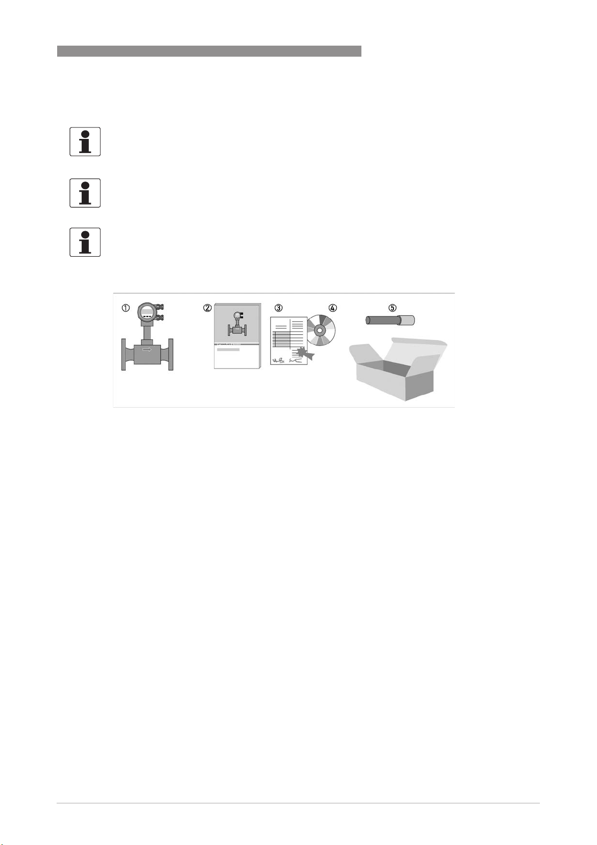
Figure 2-1: Scope of delivery
1 Measuring device in ordered version
2 Quick Start
3 Certificates, calibration report and parameter datasheet
4 CD with complete documentation
5 Bar magnet
2.2 Device versions
The devices are delivered in the following variants:
• Signal converter with display
• Measuring sensor in flanged design, Sensor F
• Measuring sensor in sandwich design, Sensor S
• Remote version - Measuring sensor with separated remote signal converter
The following designs are available as options:
• with pressure sensor
• with shut-off valve for the pressure sensor
• Flange version, measuring sensor with single reduction F1R
• Flange version, measuring sensor with double reduction F2R
www.krohne.com04/2016 - 4000150609 - MA OPTISWIRL 4070C R10 en
11
Page 12
2
DEVICE DESCRIPTION
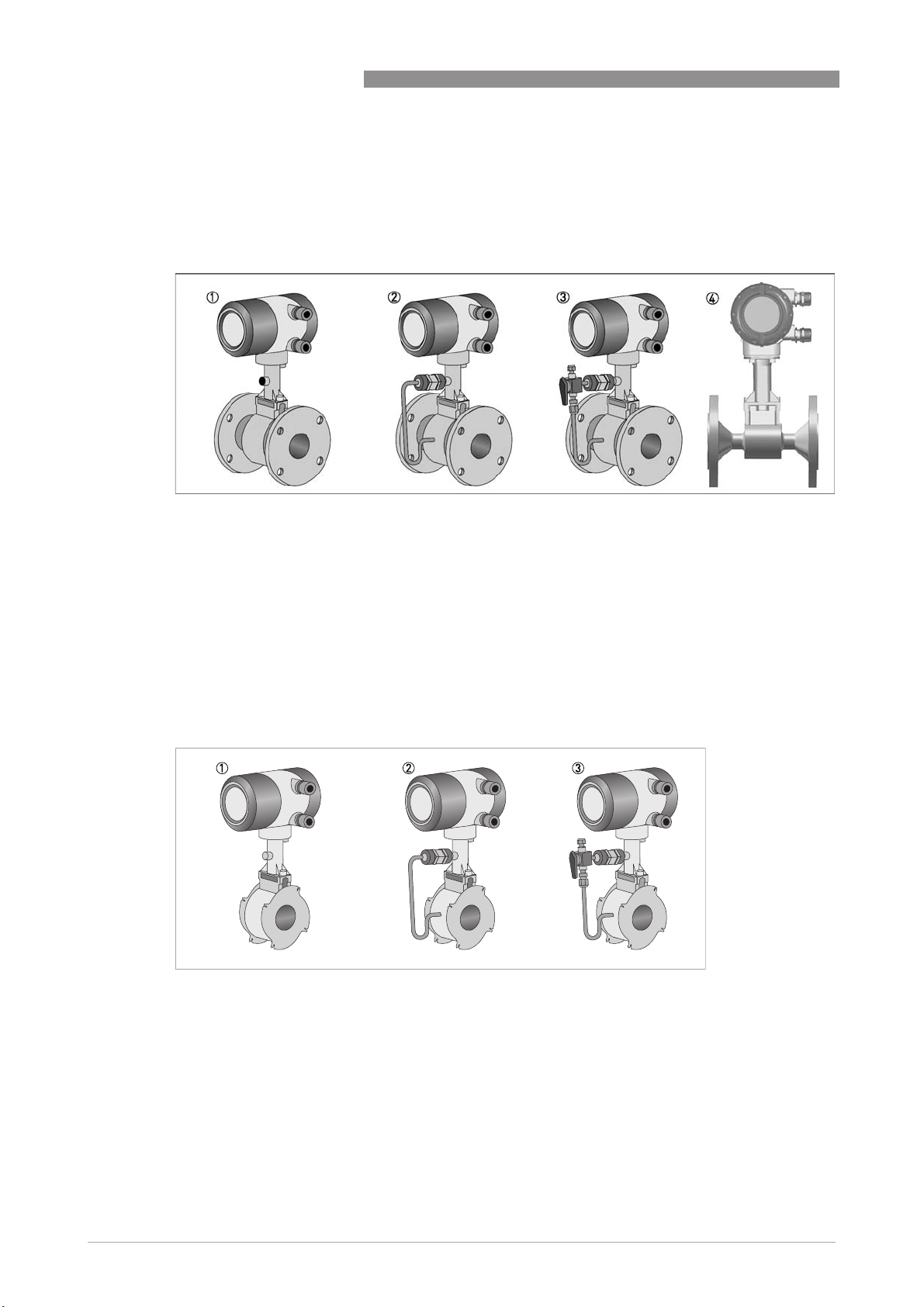
2.2.1 Devices with connection flange
The measuring system consists of a measuring sensor and a signal converter. These elements
form a permanent mechanical unit.
Figure 2-2: Flanged devices with display
1 Version with temperature sensor
2 Version with temperature sensor and optional pressure sensor
3 Version with temperature sensor, optional pressure sensor and shut-off valve
4 Flange sensor version with inlet reduction
OPTISWIRL 4070
2.2.2 Sandwich version
The sandwich version features 2 centring rings to aid with installation.
Figure 2-3: Sandwich versions with display
1 Version with temperature sensor
2 Version with temperature sensor and optional pressure sensor
3 Version with temperature sensor, optional pressure sensor and shut-off valve
12
www.krohne.com 04/2016 - 4000150609 - MA OPTISWIRL 4070C R10 en
Page 13
OPTISWIRL 4070
DEVICE DESCRIPTION
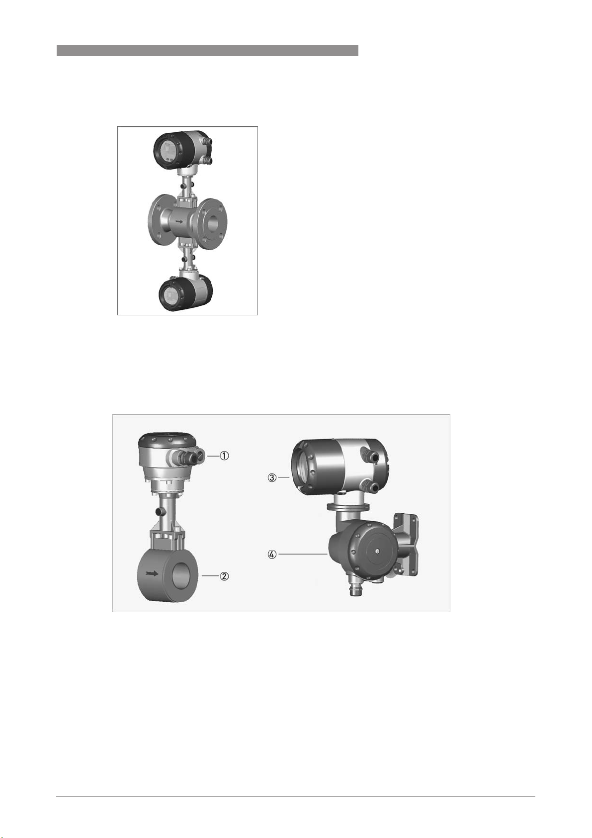
2.2.3 Devices for dual measurement and twofold reliability
This is a genuine redundant system with two
independent measuring sensors and two
signal converters.
This provides twofold functional reliability and
availability of the measurement.
This variant is ideally suited for
measurements in multi-product pipelines. In
such pipelines, two different products are
moved through one after the other.
One signal converter can be programmed for
one product, and the other signal converter
for the other product.
2
2.2.4 Device version remote
1 Sensor terminal box
2 Sensor
3 Signal converter
4 Wall mount bracket connection box
With the remote variant, the measuring sensor and signal converters are located separately. The
10-pin, shielded connection cable may not exceed 15m in length.
The marking of the devices is shown on the nameplates below (see also description code). On
both the compact devices and the remote versions, the main plate is located on the converter
housing. On the remote versions there is an additional marking on the measuring sensor.
www.krohne.com04/2016 - 4000150609 - MA OPTISWIRL 4070C R10 en
13
Page 14
2
DEVICE DESCRIPTION
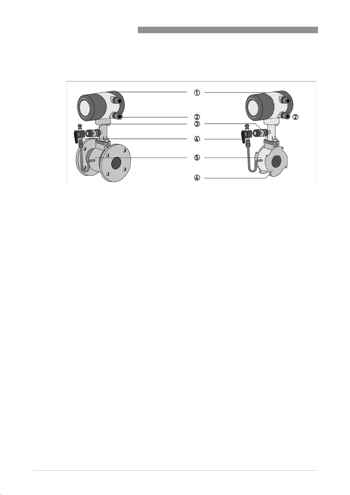
2.2.5 Device description
Figure 2-4: Device description
1 Signal converter
2 Cable feedthrough grey, standard version
3 Pressure sensor, optional
4 Shut-off valve, optional
5 Measuring sensor
6 Centering ring
OPTISWIRL 4070
2.2.6 Free air delivery measurement - FAD (optional)
A (air) compressor draws air from the ambient atmosphere, compresses it and delivers it at the
required pressure. Since the ambient atmosphere also contains water vapour, what the
compressor draws in is a mixture of air and water vapour. Free air delivery measurement is to
be understood under this condition. Most manufacturers specify free air delivery only at
standard intake conditions. What the user ultimately requires as process air must first be
determined before measuring can take place with an accuracy of ±1%.
The vortex flowmeter with the optional FAD function can measure the free air delivery online,
humidity and speed compensated, regardless of its function as standard flowmeter. The
integrated software evaluates the free air delivery automatically online.
The menu-driven, user-friendly software prompts the operator to enter the pressure, relative
humidity, the required as well as current discharge pressure.
The steam tables and compressibility tables are saved as standard. The measuring device is
optionally available with a pressure sensor which measures the discharge pressure online,
making manual input of the values unnecessary.
14
www.krohne.com 04/2016 - 4000150609 - MA OPTISWIRL 4070C R10 en
Page 15

OPTISWIRL 4070
2.2.7 Gross heat meter
In almost all applications with saturated steam, the steam is used for heating. It is much more
interesting to know how great the heat flow volume is that is available to the process, than to
know how great the flow is in kg/h.
As the enthalpy of steam changes with the temperature, it cannot be assumed as a constant. The
vortex flowmeter has a special feature that can calculate the flow of vapour as power output. The
enthalpy tables are permanently programmed in the memory of the device.
The online density-compensated mass flow is multiplied by the correct enthalpy to obtain the
flow as power output.
DEVICE DESCRIPTION
2
Power [Q
If the gross heat meter is activated, both the totalizer for the absolute steam consumption as
well as that for the energy run internally.
] = mass flow [Qm] x enthalpy [H]
H
www.krohne.com04/2016 - 4000150609 - MA OPTISWIRL 4070C R10 en
15
Page 16
2
DEVICE DESCRIPTION
2.2.8 Dual seal
To comply with the requirements of ANSI/ISA 12.27.01-2003 "Requirements for Process Sealing
Between Electrical Systems and Flammable or Combustible Process Fluid", a membrane vent is
integrated in the neck of the device. This vent is located between the primary seal (process) and
the secondary seal (electronics compartment) and works to prevent pressure build-up in the
device neck, thus preventing product from penetrating the electronics compartment in the
unlikely event of a leak in the primary seal.
OPTISWIRL 4070
1 Membrane vent
The seal between the pick-up and the measuring tube is considered as the primary seal. The
material used for it is always the same as that used for the measuring tube itself (e.g. stainless
®
steel 1.4404 / 316L or Hastelloy
relation to process parameters (media, temperature) must be taken into account.
By using the membrane vent, all requirements for a "DUAL SEAL" version in terms of the above
mentioned standards are met.
• It protects the electronics from the process media.
• Any leak in the primary seal can be detected.
Even though there is no reason to expect the seal to fail, regular visual checks should still be
carried out to detect any possible leak as early as possible.
In the event of a leak, contact the manufacturer's service department to service or replace the
device.
C22). When selecting a material, corrosion resistance in
16
www.krohne.com 04/2016 - 4000150609 - MA OPTISWIRL 4070C R10 en
Page 17
OPTISWIRL 4070
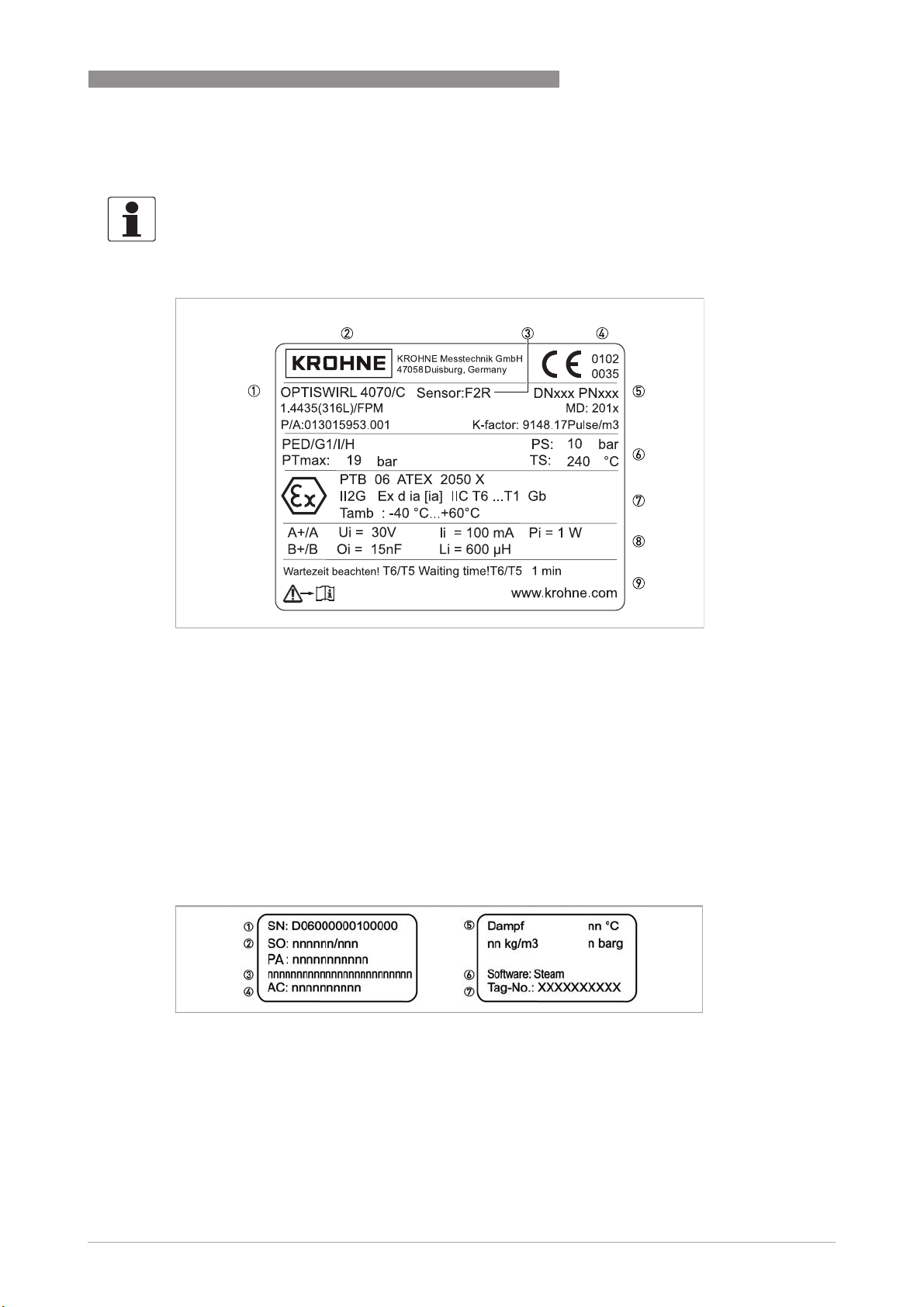
2.3 Nameplate
INFORMATION!
Check the device nameplate to ensure that the device is delivered according to your order. Check
for the correct supply voltage printed on the nameplate.
DEVICE DESCRIPTION
2
Figure 2-5: Example of nameplate
1 Device type
2 Manufacturer
3 Sensor:
S - Sandwich
F - Flange
F1R - Flange single reduction
F2R - Flange double reduction
4 Notified bodies for ATEX & PED (only available if this option was ordered)
5 Connection data: nominal diameter and pressure rating
6 PED data
7 Ex data (only available if this option was ordered)
8 Electrical connection data
9 Manufacturer's website
Figure 2-6: Example of nameplate
1 Serial number
2 Order number
3 Type code
4 Item number
5 Fluid data
6 Software variant
7 Tag number
www.krohne.com04/2016 - 4000150609 - MA OPTISWIRL 4070C R10 en
17
Page 18
2
DEVICE DESCRIPTION
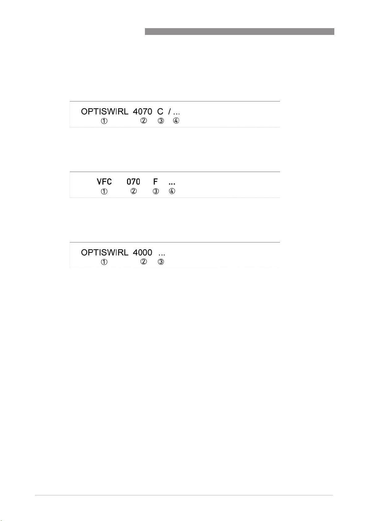
2.4 Description code
The description code* consists of the following elements:
Compact device
1 Product designation
2 Type series
3 Compact measuring device
4 Marking without influence on the explosion safety protection
Signal converter remote version
1 Product designation
2 Type series
3 Remote version
4 Marking without influence on the explosion safety protection
OPTISWIRL 4070
Sensor remote version
1 Product designation
2 Type series sensor
3 Marking without influence on the explosion safety protection
* positions which are not needed are omitted (no blank positions)
The remote version consisting of the OPTISWIRL 4000 flow sensor and the VFC 070 F signal
converter is called the OPTISWIRL 4070 F.
18
www.krohne.com 04/2016 - 4000150609 - MA OPTISWIRL 4070C R10 en
Page 19
OPTISWIRL 4070
3.1 General notes on installation
INFORMATION!
Inspect the packaging carefully for damages or signs of rough handling. Report damage to the
carrier and to the local office of the manufacturer.
INFORMATION!
Do a check of the packing list to make sure that you have all the elements given in the order.
INFORMATION!
Look at the device nameplate to ensure that the device is delivered according to your order.
Check for the correct supply voltage printed on the nameplate.
3.2 Storage
• Store the device in a dry, dust-free location.
• Avoid extended direct exposure to the sun.
• Store the device in the original packaging.
• The permissible storage temperature for standard devices is -40...+85°C / -40...+185°F.
INSTALLATION
3
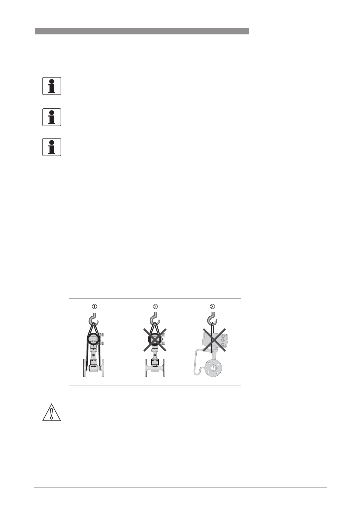
3.3 Transport
• Use lifting straps wrapped around both process connections for transport.
• Do not lift measuring devices by the signal converter housing for transport.
• Never lift the measuring device by the pressure sensor.
• Do not use lifting chains as they may damage the housing.
Figure 3-1: Transport instructions
CAUTION!
Non-secured devices can pose risk of injury. The centre of mass of the device is often higher
than the point at which the lifting straps are attached.
Prevent the measuring device from sliding or rotating accidentally.
www.krohne.com04/2016 - 4000150609 - MA OPTISWIRL 4070C R10 en
19
Page 20
3
INSTALLATION
3.4 Installation conditions
INFORMATION!
For accurate volumetric flow measurement the measuring device needs a completely filled pipe
and a fully developed flow profile.
Please observe the instructions regarding inlet and outlet pipe runs as well as the installation
position.
CAUTION!
Eliminate vibrations in the pipeline by properly installing the measuring device. Any vibration will
distort the measuring result.
CAUTION!
When installing the device in the piping, the following points must be observed:
•
Nominal diameter of connection pipe flange = nominal flange diameter of pipe!
•
Use flanges with smooth holes, e.g. welding neck flanges.
•
Align carefully the holes of the connecting flange and the flowmeter flange.
•
Check the compatibility of the gasket material with the process product.
•
Make sure that the gaskets are arranged concentrically. The flange gaskets must not project
into the pipe cross-section.
•
The flanges have to be concentric.
•
There must not be any pipe bends, valves, flaps or other internals in the immediate inlet run.
•
Devices in sandwich version may only be installed using a centering ring.
•
Never install the device directly behind piston compressors or rotary piston meters.
•
Do not lay signal cables directly next to cables for the power supply.
OPTISWIRL 4070
INFORMATION!
If there is a risk of water hammers in steam networks, appropriate condensate separators must
be installed.
Suitable measures must be taken to avoid water cavitation if it is a possible risk.
20
www.krohne.com 04/2016 - 4000150609 - MA OPTISWIRL 4070C R10 en
Page 21
OPTISWIRL 4070
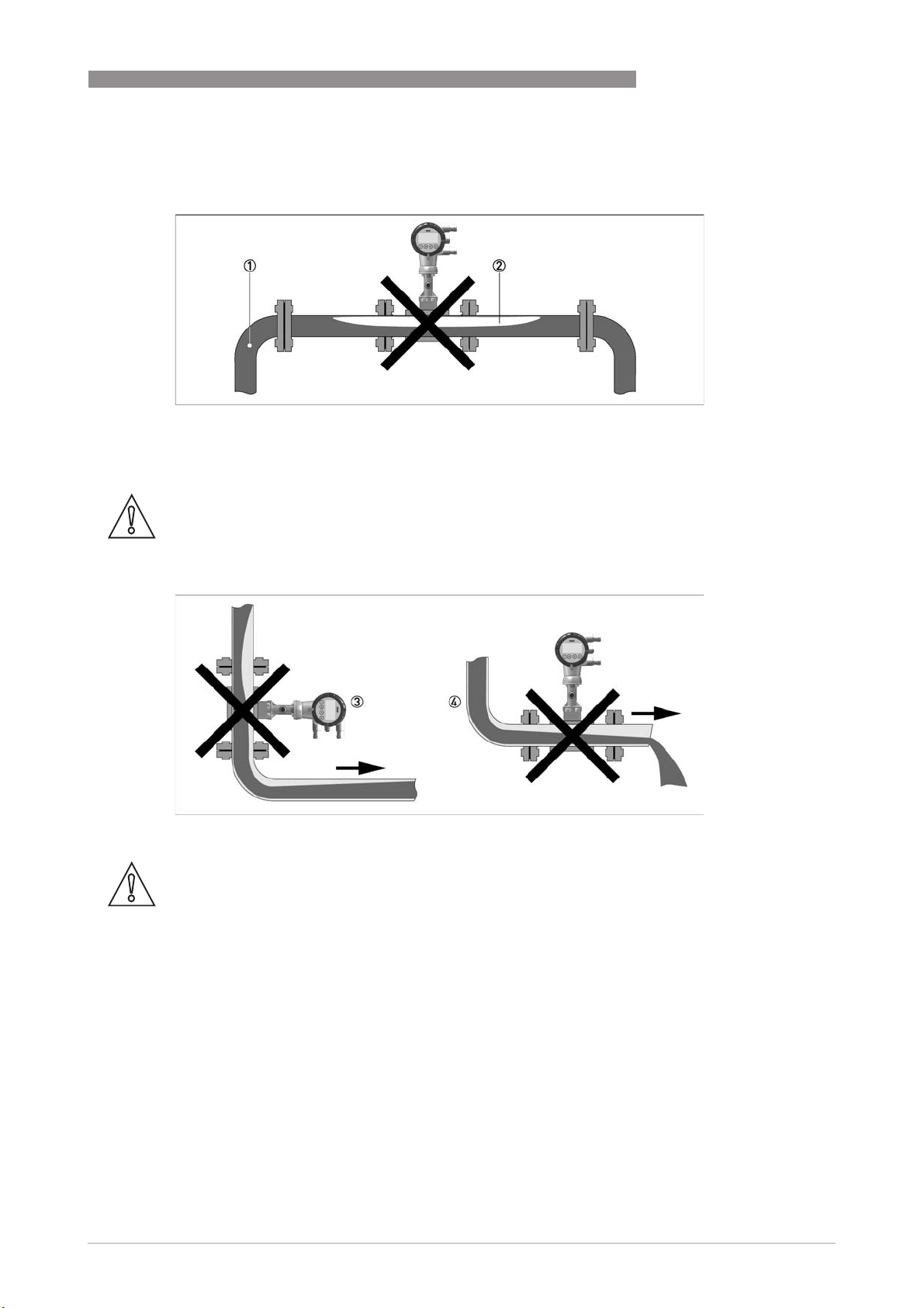
3.4.1 Prohibited installation when measuring liquids
Figure 3-2: Upper pipe bend
CAUTION!
Prohibited: Installing the device in an upper pipe bend 1, because there is a risk of gas bubbles
2 forming. Gas bubbles can lead to pressure surges and inaccurate measurement.
INSTALLATION
3
Figure 3-3: Downstream pipe and outlet
CAUTION!
Installing the device in a downstream pipe 3 or upstream pipe of an outlet 4. There is the risk of
partially filled pipes leading to inaccurate measurements.
www.krohne.com04/2016 - 4000150609 - MA OPTISWIRL 4070C R10 en
21
Page 22
3
INSTALLATION
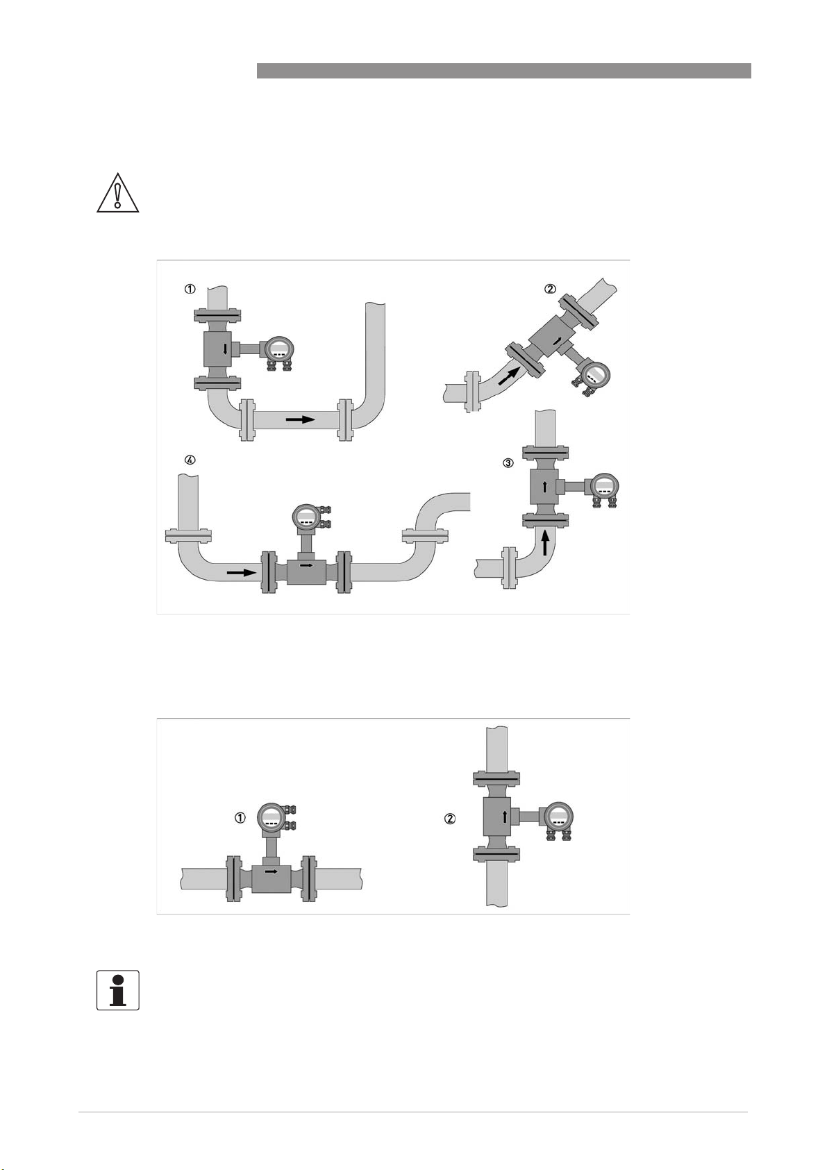
3.4.2 Recommended installations for measurement of liquids
CAUTION!
The required inlet and outlet sections must be observed.
OPTISWIRL 4070
1 If the device is installed in a downpipe, a standpipe must be installed immediately after it.
2 Installing the device in an inclined standpipe.
3 Installing the device in a vertical standpipe.
4 Installing the device in the lower pipe bend.
1 Above a horizontal pipe
2 On a vertical pipe
INFORMATION!
Depending on the installation position, you may have to rotate the display and/or the connection
housing.
22
www.krohne.com 04/2016 - 4000150609 - MA OPTISWIRL 4070C R10 en
Page 23
OPTISWIRL 4070
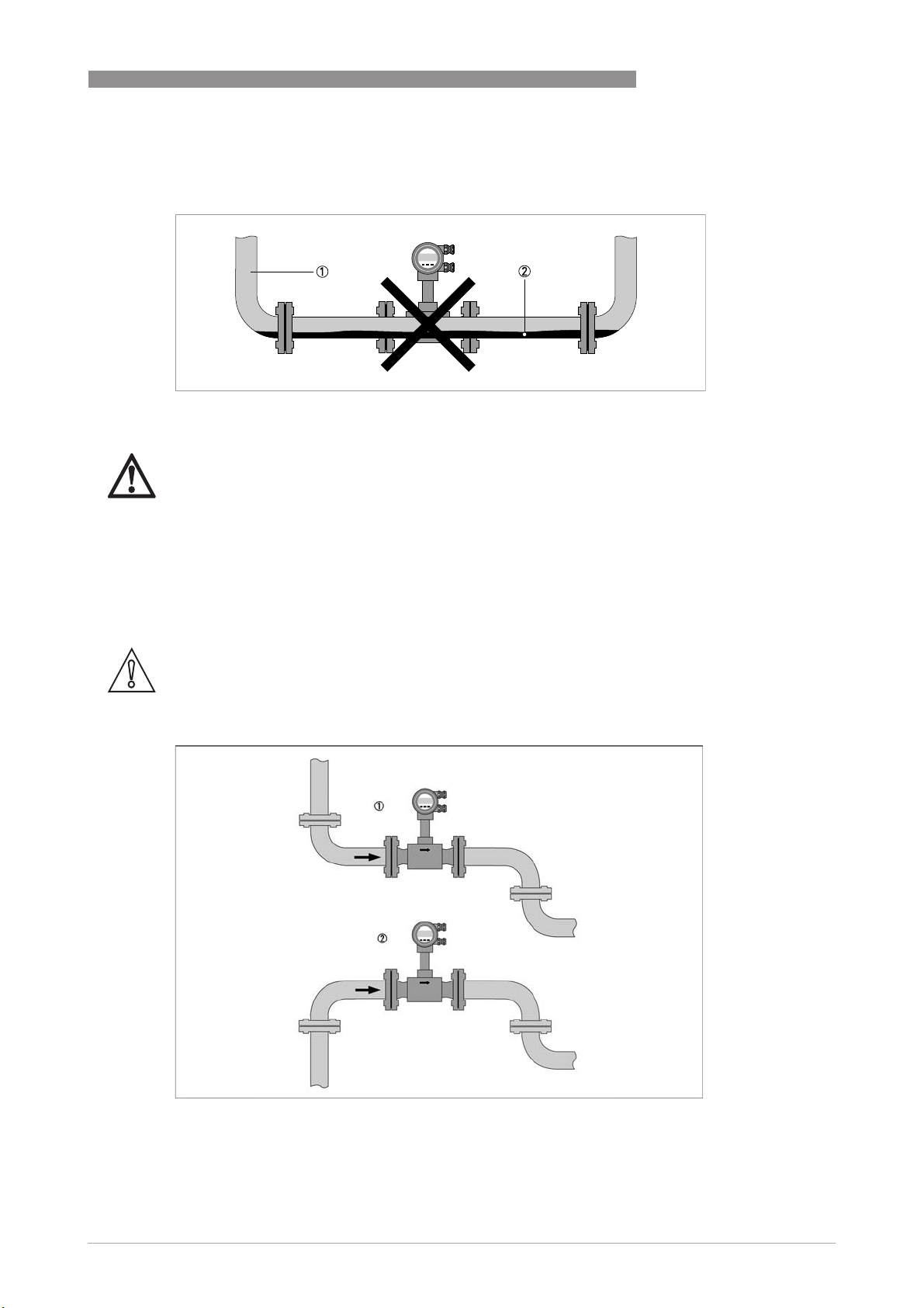
3.4.3 Prohibited installation when measuring vapours and gases
1 Lower pipe bends
2 Condensate
DANGER!
Prohibited: Installing the device in a lower pipe bend 1, because there is a risk of condensate
forming 2.
Condensate can lead to cavitation and inaccurate measurement. Under certain circumstances
the device can be destroyed and the measured product can leak.
INSTALLATION
3
3.4.4 Recommended installations for measurement of steam and gases
CAUTION!
The required inlet and outlet sections must be observed.
1 Inlet and outlet falling
2 Rising inlet - falling outlet
www.krohne.com04/2016 - 4000150609 - MA OPTISWIRL 4070C R10 en
23
Page 24
3
INSTALLATION
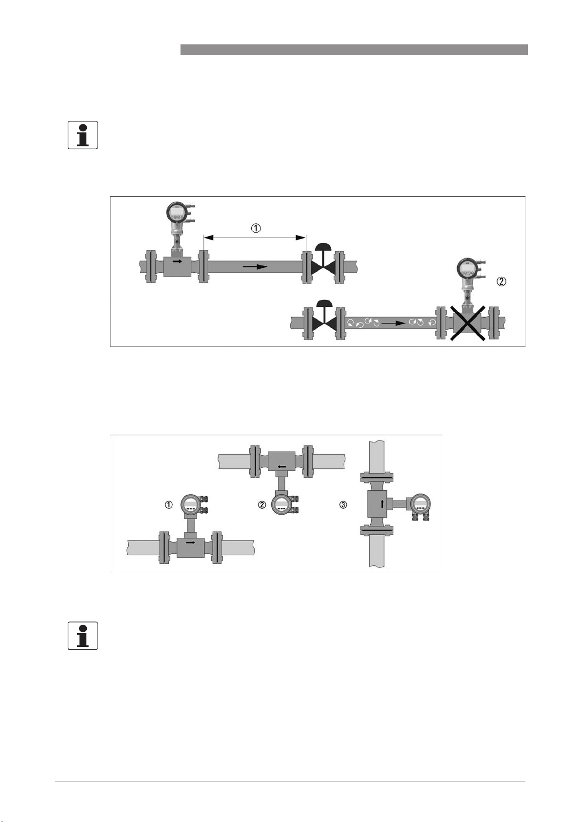
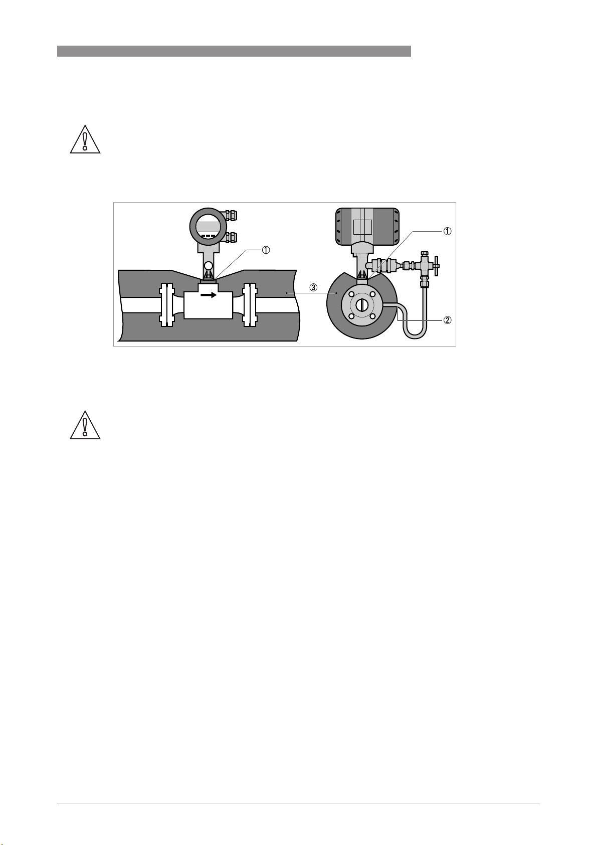
3.4.5 Pipelines with control valve
INFORMATION!
To ensure smooth and correct measurement, the manufacturer recommends not installing the
measuring device downstream from a control valve. This would run the risk of vortex formation,
which would distort the measuring result.
OPTISWIRL 4070
Figure 3-4: Pipeline with control valve
1 Recommended: installing the device before the control valve at a distance of ≥ 5 DN
2 Not recommended: Installing the flowmeter directly downstream of control valves, due to vortex formation.
3.4.6 Preferred mounting position
1 above a horizontal pipe
2 underneath a horizontal pipe (not permitted with lines at risk for condensate)
3 on a vertical pipe
INFORMATION!
Depending on the installation position, you may have to rotate the display and/or the connection
housing.
24
www.krohne.com 04/2016 - 4000150609 - MA OPTISWIRL 4070C R10 en
Page 25
OPTISWIRL 4070
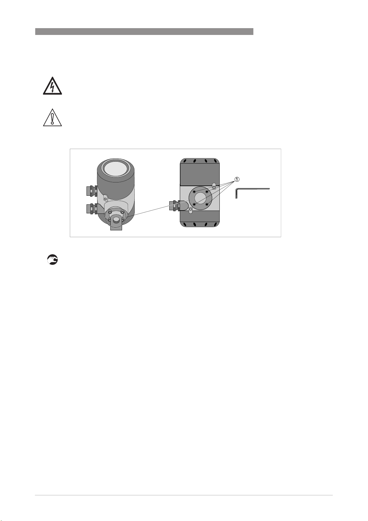
3.4.7 Turning the connection housing
DANGER!
All work on the device electrics may only be carried out by appropriately trained personnel. The
regional occupational health and safety directives must always be observed.
CAUTION!
Do not damage the electrical cable by overtwisting it.
Do not remove the electrical connector.
INSTALLATION
3
Figure 3-5: Allen screws on connection housing
• Disconnect the power supply from the measuring device.
• Loosen the four screws 1 on the rear side of the connection housing.
• Lift the connection housing and turn it to the required position in 90° steps.
• Screw the connection housing back on.
www.krohne.com04/2016 - 4000150609 - MA OPTISWIRL 4070C R10 en
25
Page 26
3
INSTALLATION
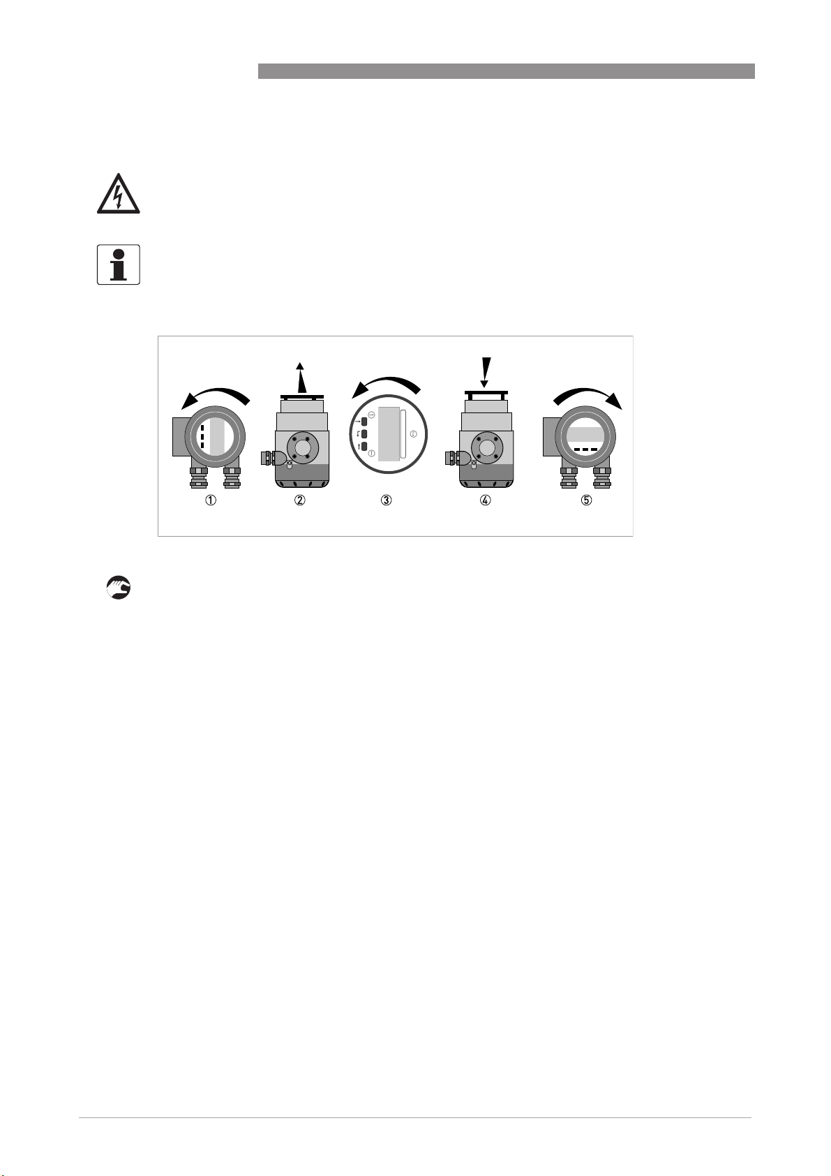
3.4.8 Turning the display
DANGER!
All work on the device electrics may only be carried out by appropriately trained personnel. The
regional occupational health and safety directives must always be observed.
INFORMATION!
If the measuring device is installed in a vertical pipe, you will have to turn the display by 90
installed below a pipe, turn 180
OPTISWIRL 4070
°
; if
°
.
Figure 3-6: Turning the display
Turn the display as follows:
• Disconnect the power supply from the measuring device.
• Unscrew the cover in front of the display 1 from the connection housing.
• Pull the display 2 carefully a few centimetres out of the anchor fitting and turn it to the
required position 3.
• Press the display onto the spacer pins 4, until it clicks.
• Turn the cover with gasket 5 back onto the housing and tighten it by hand.
26
www.krohne.com 04/2016 - 4000150609 - MA OPTISWIRL 4070C R10 en
Page 27
OPTISWIRL 4070
3.4.9 Heat insulation
CAUTION!
The area above the converter support must not be heat-insulated.
The heat insulation 3 may only extend to the maximum height 1 shown below up to the
connecting screws of the measuring sensor.
INSTALLATION
3
Figure 3-7: Heat insulation on connection piece and signal cable
1 Max. height of insulation up to intermediate piece between measuring sensor and signal converter
2 Max. thickness of the insulation up to the bend of the pressure pipe
3 Insulation
CAUTION!
The heat insulation 3 may only extend as far as the bend of the pressure sensing line 2.
www.krohne.com04/2016 - 4000150609 - MA OPTISWIRL 4070C R10 en
27
Page 28

3
INSTALLATION
3.5 Inlet and outlet runs
3.5.1 Minimum inlet runs
OPTISWIRL 4070
1 General inlet run without disturbing flow ≥ 20 DN
2 Behind a control valve ≥ 50 DN
3 After a pipe diameter reduction ≥ 20 DN
28
1 After a single bend 90° ≥ 20 DN
2 After a double bend 2x90° ≥ 30 DN
3 After a double three-dimensional bend 2x90° ≥ 40 DN
www.krohne.com 04/2016 - 4000150609 - MA OPTISWIRL 4070C R10 en
Page 29

OPTISWIRL 4070
3.5.2 Minimum outlet sections
INSTALLATION
3
Figure 3-8: Minimum outlet sections
1 Upstream of pipe expanders, pipe bends, control valves, etc. ≥ 5 DN
2 Upstream of metering points ≥ 5 … 6 DN
INFORMATION!
The interior of the pipe at the metering points must be free of burrs and other flow impediments.
The measuring device has an internal temperature sensor. The distance from external
temperature measuring points must be ≥ 5 DN. Use measuring sensors that are as short as
possible to avoid disturbances of the flow profile.
3.5.3 Flow straightener
If, due to the type of installation, the required inlet runs are not available, the manufacturer
recommends using flow straighteners. Flow straighteners are installed between two flanges
upstream of the device and shorten the required inlet run.
Figure 3-9: Flow straightener
1 Straight inlet run upstream of straightener ≥ 2 DN
2 Flow straightener
3 Straight pipe run between flow straightener and device ≥ 8 DN
4 Minimum straight outlet run ≥ 5 DN
www.krohne.com04/2016 - 4000150609 - MA OPTISWIRL 4070C R10 en
29
Page 30

3
INSTALLATION
3.6 Installation
3.6.1 General installation notes
CAUTION!
Installation, assembly, start-up and maintenance may only be performed by appropriately
trained personnel. The regional occupational health and safety directives must always be
observed.
The following procedures have to be carried out before installing the device:
• Ensure that the gaskets have the same diameter as the pipelines.
• Note the correct flow direction for the device. This is indicated by an arrow on the neck of the
flow sensor.
• On measuring points with varying thermal loads, the devices have to be mounted with stress
bolts (DIN 2510).
• Stress bolts or bolts and nuts are not included in the scope of delivery.
• Ensure that the measuring flange is concentrically fitted.
• Note the exact installation length of the measuring device when preparing the measuring
point.
OPTISWIRL 4070
Figure 3-10: Preparing the metering point
1 Installation length of measuring device + thickness of gaskets.
CAUTION!
The internal diameter of the pipelines, the flow sensor and the gaskets must match. The gaskets
may not protrude into the flow.
Figure 3-11: Inner diameter
1 Inner diameter of connection pipe
2 Inner diameter of flange and gasket
3 Inner diameter of flow sensor
30
www.krohne.com 04/2016 - 4000150609 - MA OPTISWIRL 4070C R10 en
Page 31

OPTISWIRL 4070
3.6.2 Installing devices in flange design
INSTALLATION
3
Figure 3-12: Installing devices in flange design
1 Gasket
2 Bolts with fixing nuts
• Use bolts and fastening nuts 2 to attach the measuring device to one side of the flange.
• While doing so, insert the gaskets 1 between measuring sensor and flange and align them.
• Check that the gasket is concentric and that it is not protruding into the pipe cross-section.
• Install the gasket, bolts and fastening nuts on the other side of the flange.
• Align the measuring device and the gaskets so they are concentric.
• Now tighten all nuts bit by bit alternately across the diagonal.
www.krohne.com04/2016 - 4000150609 - MA OPTISWIRL 4070C R10 en
31
Page 32

3
INSTALLATION
3.6.3 Installing devices in sandwich design
OPTISWIRL 4070
Figure 3-13: Installation using centering ring
1 Flow sensor
2 Centering ring
3 Bolts with fixing nuts
4 Drill hole
5 Sealing
• Push the first bolt 3 through the hole 5 of both flanges.
• Screw on the nuts and washers to both ends of the bolt 3 but do not tighten them.
• Install the second bolt through the holes 4.
• Place the measuring sensor 1 between the two flanges.
• Insert the gaskets 6 between measuring sensor 1 and flanges and align them.
• Check that the flange is concentric.
• Install the remaining bolts, washers and nuts. Do not yet tighten the nuts.
• Turn the centring ring 2 in a counter-clockwise direction and align the device.
• Check that the gaskets 6 are concentric; they must not protrude into the pipe cross-section.
• Now tighten all nuts bit by bit alternately across the diagonal.
32
www.krohne.com 04/2016 - 4000150609 - MA OPTISWIRL 4070C R10 en
Page 33

OPTISWIRL 4070
4.1 Safety instructions
DANGER!
All work on the electrical connections may only be carried out with the power disconnected. Take
note of the voltage data on the nameplate!
DANGER!
Observe the national regulations for electrical installations!
DANGER!
For devices used in hazardous areas, additional safety notes apply; please refer to the Ex
documentation.
WARNING!
Observe without fail the local occupational health and safety regulations. Any work done on the
electrical components of the measuring device may only be carried out by properly trained
specialists.
ELECTRICAL CONNECTIONS
4
INFORMATION!
Look at the device nameplate to ensure that the device is delivered according to your order.
Check for the correct supply voltage printed on the nameplate.
www.krohne.com04/2016 - 4000150609 - MA OPTISWIRL 4070C R10 en
33
Page 34

4
ELECTRICAL CONNECTIONS
4.2 Connecting the signal converter
1 Housing cover of the electrical terminal compartment
2 Electrical connection terminals with the housing cover open
3 Terminal A current output -
4 Terminal A+ current output +
5 Terminal B pulse output -
6 Terminal B+ Pulse output +
7 Ground terminal in housing
8 Ground terminal on connection piece between measuring sensor and signal converter.
OPTISWIRL 4070
Both grounding terminals 7 and 8 are equally effective from a technical point of view.
The following procedures are to be performed:
• Unscrew the housing cover 1 of the electrical terminal compartment.
• Feed the connection cable through the cable entry in the housing.
• Connect the cable for the current output and the cable for the optional pulse output as shown
in the cable terminal diagrams below. To facilitate installation the connection plug can be
removed from the device. The plug is configured in such a way as to prevent reverse polarity.
• Connect the grounding to the terminal 7, alternatively use the PE terminal on the connection
piece between the measuring sensor and the signal converter 8.
• Tighten the cable glands.
• Hand-tight the housing cover with gasket.
34
www.krohne.com 04/2016 - 4000150609 - MA OPTISWIRL 4070C R10 en
Page 35

OPTISWIRL 4070
ELECTRICAL CONNECTIONS
4.3 Electrical connection of current and pulse output
• Current output:
Current output:
Current output:Current output:
In some cases, a shielded or twisted cable may be necessary. The cable shield may only be
earthed (grounded) at one place (on the power supply unit).
• Pulse output:
Pulse output:
Pulse output:Pulse output:
When using the pulse output, two separate signal circuits are necessary if the pulse output is
utilized together with analogue signals. Each signal circuit requires its own power supply.
The total resistance must be adapted so that the total current I
• Connection current output on terminals A, A+
Connection pulse output on terminals B, B+
does not exceed 100 mA.
tot
4
Figure 4-1: Electrical connection of current and pulse output
1 Power supply per signal circuit
2 Optional display unit
3 Load for HART
4 e.g. counter
®
≥ 250 Ω
The maximum load resistance is calculated as follows:
www.krohne.com04/2016 - 4000150609 - MA OPTISWIRL 4070C R10 en
35
Page 36

4
ELECTRICAL CONNECTIONS
4.3.1 Power supply
INFORMATION!
The supply voltage has to be between 14 VDC and 36 VDC. This is based on the total resistance of
the measuring loop. To determine this, add up the resistances of each component in the
measuring loop (not including the measuring device).
The required supply voltage can be calculated using the formula below:
= RL * 22mA + 14V
U
ext.
where
U
= the minimum supply voltage and
ext.
R
= the total measuring loop resistance is.
L
INFORMATION!
The power supply has to be able to supply a minimum of 22 mA.
OPTISWIRL 4070
4.3.2 Totalizer / pulse output
The base units for the totalizer and the pulse output are mmmm
3333
norm.
norm. for standard volume and kg
mmmm
norm.norm.
The unit and the conversion factor can be changed in menu item 3.2.8 "Conf.Tot". User specific
units (User Def.) can also be entered but the conversion factor must always be entered based on
the base unit. For a sample calculation see chapter 6.2.5 "Change units".
The maximum frequency of the pulse output is 0.5 Hz.
Figure 4-2: pulse output
1 f
≤ 0.5 Hz
max
2 closed
3 open
4 Pulse ≥ 250 ms
kg for mass.
kgkg
3333
for volume,
36
www.krohne.com 04/2016 - 4000150609 - MA OPTISWIRL 4070C R10 en
Page 37

OPTISWIRL 4070
The pulse output is a passive "open collector" output which is electrically separated from the
current interface and the measuring sensor. It can be configured as a high current output or
NAMUR output using a jumper on the amplifier board.
Jumper in NAMUR setting
Jumper in NAMUR setting
Jumper in NAMUR settingJumper in NAMUR setting
Ri = 900 Ω U
= 36 VDC
max
ELECTRICAL CONNECTIONS
4
The maximum frequency of the pulse output is f
Jumper in high current setting
Jumper in high current setting
Jumper in high current settingJumper in high current setting
Open: Maximum voltage U
Closed: Maximum current I
= 36 VDC Closed current IR < 1 mA
max
= 100 mA Voltage U < 2 VDC
max
The maximum frequency of the pulse output is f
max
max
= 0.5 Hz
= 0.5 Hz
Figure 4-3: Jumper settings pulse output
1 Electronic insert
2 Jumper on board
3 Jumper in high current setting
4 Jumper in NAMUR setting
www.krohne.com04/2016 - 4000150609 - MA OPTISWIRL 4070C R10 en
37
Page 38

4
ELECTRICAL CONNECTIONS
4.4 Remote version connection
The connections in the sensor and wall mount bracket connection boxes are identical in
construction.
OPTISWIRL 4070
Connection cable strand colour
Connection Terminal no.: Strand colour
a Pressure sensor 5 brown
4 rose / pink
3 green
2 grey
1 white
b Temperature sensor 2 black
1 purple
c Vortex Sensor 3 red
2 yellow
1 blue
Remote connection cable
38
1 Sensor connection side - strand length approx. 100mm
2 Length of shrink hose approx. 30mm
3 Wall housing connection side - prefabricated shielding - length approx. 15mm
www.krohne.com 04/2016 - 4000150609 - MA OPTISWIRL 4070C R10 en
Page 39

OPTISWIRL 4070
Connection of shielding connection cable remote version
CAUTION!
The cable shielding is connected only on one side under the U-clamp terminal 1 in the wall
mount bracket connection box.
ELECTRICAL CONNECTIONS
4
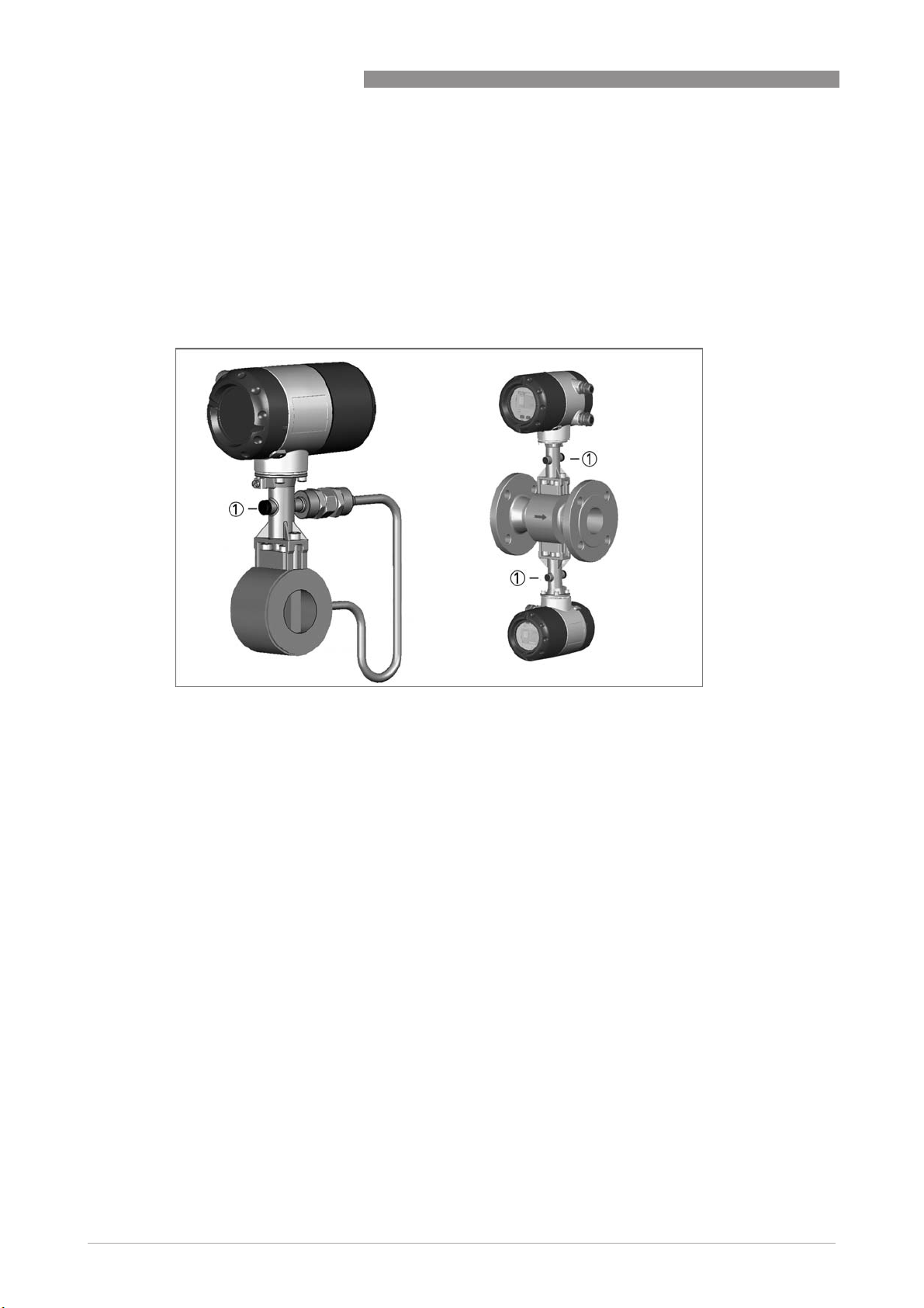
4.5 Grounding connections
The grounding can be done either by connecting the PE terminal in the housing or the PE
terminal on the connection piece between measuring sensor and signal converter. Both of these
electrical connections are equally effective from a technical point of view.
Ground connection compact version
1 Electrical grounding connection on connection piece between measuring sensor and signal converter.
2 Electrical grounding connection on housing
CAUTION!
The measuring device has to be grounded properly to achieve accurate measurement. The
grounding wire may not transfer any interference voltage.
Do not use this grounding cable to ground any other electrical devices.
www.krohne.com04/2016 - 4000150609 - MA OPTISWIRL 4070C R10 en
39
Page 40

4
ELECTRICAL CONNECTIONS
Grounding connection remote version
1 Grounding connection on sensor side
2 Grounding connection on signal converter side
OPTISWIRL 4070
CAUTION!
Both device parts have to be grounded properly to achieve accurate measurement. The
grounding wire may not transfer any interference voltage.
40
www.krohne.com 04/2016 - 4000150609 - MA OPTISWIRL 4070C R10 en
Page 41

OPTISWIRL 4070
4.6 Ingress protection
The converter electronics housing meets the requirements for IP66/67 in accordance with
EN60529 both for the compact and for the remote version. For the remote version, the sensor
electronics housing meets the requirements for IP66/68.
CAUTION!
After all servicing and maintenance work on the measuring device, the specified protection
category must be ensured again.
ELECTRICAL CONNECTIONS
4
Figure 4-4: Cable feedthrough
Therefore it is essential to observe the following points:
• Use only original gaskets. They must be clean and free of any damage. Defective gaskets must
be replaced.
• The electrical cables used must be undamaged and must comply with regulations.
• The cables must be laid with a loop 1 upstream of the measuring device to prevent water
from getting into the housing.
• The cable feedthroughs 2 must be tightened. Note that the clamping range of the cable
feedthrough corresponds to the outer diameter of the cable.
• Align the measuring device so that the cable feedthrough is never facing up 3.
• Close any unused cable feedthroughs using blind plugs 4 suitable for the protection category.
• Do not remove the required cable bushing from the cable feedthrough.
www.krohne.com04/2016 - 4000150609 - MA OPTISWIRL 4070C R10 en
41
Page 42

5
START-UP
5.1 Start
After the device is switched on, the display shows the following in sequence
1. Testing...
2. Device type
Sofware Version - Revision
The device performs a self-test and switches to measurement mode. Here, all of the parameters
preset for the customer are analysed and checked for plausibility, and the current measured
value is displayed.
5.2 Start-up and control
INFORMATION!
The flowmeter is largely maintenance-free.
Observe the application limits in respect of temperature and medium. Additional information
refer to Technical data on page 71
OPTISWIRL 4070
.
42
www.krohne.com 04/2016 - 4000150609 - MA OPTISWIRL 4070C R10 en
Page 43

OPTISWIRL 4070
6.1 Display and operating elements
With the cover open the device is operated by using the mechanical keys on the front; with the
cover closed a bar magnet is used.
CAUTION!
The switching point of the magnetic sensors is directly under the glass panel above the
appropriate symbol. Only touch the symbol vertically and from the front using the bar magnet.
Touching it from the side may cause a malfunction
OPERATION
6
Figure 6-1: Display and operating elements
1 Enter button (bar magnet)
2 Right button (bar magnet)
3 Up button (bar magnet)
4 Up button (mechanical)
5 Enter button (mechanical)
6 Right button (mechanical)
7 Display
www.krohne.com04/2016 - 4000150609 - MA OPTISWIRL 4070C R10 en
43
Page 44

6
OPERATION
The mechanical keys and keys for the bar magnet have the same functionality. In this
documentation the keys are represented as symbols to describe the operating functions:
Mechanical Bar magnet Symbol
Table 6-1: Description of keys
6.2 Operating principles
OPTISWIRL 4070
→
↑
^
6.2.1 Functional description of the keys
→ Switch from measuring mode to menu mode
Switch to one menu level lower
Open menu item and activate change mode
In change mode:
In change mode: Move the input cursor one position to the right; after the last digit the
In change mode:In change mode:
input cursor jumps back to the beginning.
↑ In measuring mode:
^^^^ Switch to one menu level higher
Table 6-2: Description of the operating keys
In measuring mode: Switch between measured values and error messages
In measuring mode:In measuring mode:
Change between the menu items within a menu level
In change mode:
In change mode: Changing parameters and settings; running through the available
In change mode:In change mode:
characters; shifting the decimal point to the right.
Return to measuring mode with a query whether the data should be accepted
6.2.2 Switch from measuring mode to menu mode
Measuring mode Operation Menu mode
156.3
156.3
156.3156.3
kg/h
kg/h
kg/hkg/h
→ 1.1.1
1.1.1
1.1.11.1.1
Language
Language
LanguageLanguage
44
www.krohne.com 04/2016 - 4000150609 - MA OPTISWIRL 4070C R10 en
Page 45

OPTISWIRL 4070
6.2.3 Navigation within the menu structure
Navigation within the menu is by means of the → and ^ buttons. Pressing → button takes you
one menu level lower, ^ takes you one menu level higher.
If you are already located at the lowest level (function level), you can use the → button to go in
the change mode, which can be used to set data and values.
If you are located at the first level (main menu), you can use the ^ key to exit the menu mode and
return to the measuring mode.
OPERATION
6
Measuring
mode
Table 6-3: Navigation menu structure
→ Main menu↑→ Sub-menu↑→ Function
^^^^ ^^^^ ^^^^ ^^^^
6.2.4 Changing the settings in the menu
• Use the → and ↑ keys to navigate in the menu in which you want to change a setting or value.
Use the → key to activate the change mode in the selected menu.
i The current values or settings are displayed.
• Use the → and ↑ keys to change the value or setting.
Save the new value or setting using the ^ key.
Some menu items contain several setting options. They are displayed in sequence by pressing
the ^ key.
i Takes you back to the main menu.
• Press the ^ key to save the settings.
i The query "Save Yes" appears. Switch between "Yes" and "No" by pressing the ↑ key.
Switch between "YES" and "NO" by pressing the ↑ key.
↑
→ Edit
→
↑
^^^^
Save Yes ^^^^ Changes saved.
Save No ^^^^ Changes not saved.
An update is carried out and the display returns to measuring mode.
The display returns to measuring mode.
CAUTION!
Each time parameters or settings are changed, the measuring device carries out an internal
plausibility check.
If implausible inputs have been made, the display remains in the current menu, and the changes
are not saved.
www.krohne.com04/2016 - 4000150609 - MA OPTISWIRL 4070C R10 en
45
Page 46

6
OPERATION
Example: changing the default parameter from m3/h to l/min
OPTISWIRL 4070
Procedure Display Procedure Display
1 3 x
2 3 x
3 →
4 3 x
3 x → 1.1.1111
3 x 3 x
3 x ↑ 1.1.4444
3 x 3 x
3 x ↑ L/min
3 x 3 x
6.2.5 Changing units
When entering numbers and values in floating point format, the maximum possible accuracy is
0.003%. The accuracy depends on both the position of the decimal point and the length of the
number entered.
Numerical values and factors are displayed in the first line of the 10-digit display. Numerical
values are either displayed in floating point format (123.4567890) or are expressed in exponential
format (123456E002). The conversion factor of the totalizer and the pulse output is, however,
expressed in whole numbers.
Input values exponential format
107.2
3
/h
m
Language
Max. Flow
m3/h
Unit
Unit
5 ^^^^ 0000600.00
L/min
6 ^^^^ Display
Unit
7 ^^^^ 1111.1.4
Max. Flow
8 ^^^^ Save Yes
9 ^^^^ 1787.0000
L/min
Display position 1 2 3 4 5 6 7 8 9 10
Decimal point - • • • • - - - - -
Input values 0 ...90 ...90 ...90 ...
9
0 ...90 ...9E -
or
0
0 ...30 ...
8
To select the exponential function, the decimal point must be located between the 2nd and 5th
decimal position.
Flow units
The base units are mmmm
measurement and kg/h
3333
/h for volume flow measurement, mmmm
kg/h for mass flow measurement.
kg/hkg/h
The flow units can be changed in menu item 1.1.4 "Max.Flow".
User defined units can be entered using "User Def."
The unit (text) as well as the conversion factor (number) can be entered here.
The conversion factor must always be entered based on the base unit.
3333
/h stand.
/h stand. for standard volumetric flow
/h stand./h stand.
Conversion
Formula New unit (User Def.)
Example: 1 litre / h = 0.001 *
(User Def.) ==== A1 Coeff.
(User Def.)(User Def.)
A1 Coeff. **** Base unit
A1 Coeff.A1 Coeff.
Base unit
Base unitBase unit
m3/h
Menu items
1.1.3 Maes.Inst Volume / Standard volume / Mass
1.1.4 Max. Flow Unit (User Def.) / Text / A1 Coeff.
Unit (User Def.) / Text / A1 Coeff. / Max. Flow / Flow Displ
Unit (User Def.) / Text / A1 Coeff.Unit (User Def.) / Text / A1 Coeff.
46
www.krohne.com 04/2016 - 4000150609 - MA OPTISWIRL 4070C R10 en
Page 47

OPTISWIRL 4070
Totalizer / pulse output
The base units for the totalizer and the pulse output are mmmm
3333
norm. for standard volume and kg
mmmm
The unit and the conversion factor can be changed in menu item 3.2.8 "Tot.Conf.". User defined
units (User Def.) can be selected and entered. The conversion factor of the unit must always be
entered based on the base unit.
The maximum pulse output frequency is 0.5 Hz. To ensure that the pulse output does not exceed
0.5 Hz, the conversion factor of the totalizer must be selected and set accordingly. The pulse
output represents an exact copy of the whole number value of the internal totalizer.
Max. pulses per hour
kg for mass.
kgkg
3333
for volume,
OPERATION
6
fmax. ≤ 0.5 Hz 1 pulse-break ≥ 2 seconds Max. pulses / hour = 1800
1800 pulses
18001800
Example
Flow Qmax. Factor A1 Coef. Pulses / litre Pulses / h Comment
5.6 m3/h
0.001 1 pulse / 1 litre 5600 not possible
0.01 1 pulse / 10 litres 560 560 < 1800 = ok.
Menu items
1.1.3 Maes.Inst Volume / Standard volume / Mass
1.1.4 Max. Flow Unit (User Def.) / Text / A1 Coeff. / Max. Flow
3.2.5 Function P Yes
3.2.7 Totalizer Tot. on
3.2.8 Tot. Conf. User def. / Unit Text / A1 Coeff.
Yes / No
YesYes
Tot. on / Tot. off
Tot. onTot. on
User def. / Unit Text / A1 Coeff. / Preset Value / Reset / Display
User def. / Unit Text / A1 Coeff.User def. / Unit Text / A1 Coeff.
Max. Flow / Flow Displ
Max. FlowMax. Flow
6.2.6 Measures in the event of faulty indications
If the indications on the display or the responses to keypad commands are faulty, you have to do
a hardware reset. Switch the power supply OFF and ON again.
www.krohne.com04/2016 - 4000150609 - MA OPTISWIRL 4070C R10 en
47
Page 48

6
OPERATION
6.3 Overview of the most important functions and units
INFORMATION!
A complete list of all functions and short descriptions is provided in the appendix. All default
parameters and settings are adapted for the specific customer.
Level Designation Explanation
1.1.1 Language Select the menu language
1.1.4 Max. Flow Maximum flow rate
1.1.5 Min. Flow Minimum flow rate
1.1.6 Timeconst. Time constant, damping value [s]
2.1.1 Test I Check current output
2.1.2 Test P Test pulse output
3.1.1 Error Msg. Error indicator
Table 6-4: The most important functions
The value set is represented by a 20 mA analogue current output. If the current
value exceeds the preset value, an alarm is indicated.
The set value does not
not represent the 4 mA value of the current output.
notnot
Yes: error messages are displayed
No: error messages are suppressed. A flashing cursor at the top left indicates
that error messages are present.
OPTISWIRL 4070
Volume mass units
Volume mass units
Volume mass unitsVolume mass units
Volume Standard volume Mass
Liquids, steams, gases Air Gas Liquids, steams, gases
m3/h
3
/min
m
3
/s
m
L/h
L/min
L/s
3
/h
ft
3
/min
ft
3
/s
ft
gal/h
gal/min
gal/s
ImpGal/h
ImpGal/min
ImpGal/s
3
/h
cm
3
/min
cm
3
/s
cm
3
/h
dm
3
/s
dm
bbl/h
bbl/d
User Def.
Table 6-5: Flow measurements and units
FAD m3/h
3
FAD m
FAD m
/min
3
/s
FAD L/h
FAD L/min
FAD L/s
3
/h
FAD ft
3
/min
FAD ft
3
/s
FAD ft
User Def.
m3/h (norm)
3
/min (norm)
m
3
/s (norm)
m
L/h (norm)
L/min (norm)
L/s (norm)
3
/d (std.)
ft
3
/h (std.)
ft
3
/min (std.)
ft
3
/s (std.)
ft
User Def.
kg/h
kg/min
kg/s
t/h
t/min
t/s
lb/h
lb/min
lb/s
g/min
g/s
User Def.
48
www.krohne.com 04/2016 - 4000150609 - MA OPTISWIRL 4070C R10 en
Page 49

OPTISWIRL 4070
Unit totalizer
Unit totalizer
Unit totalizerUnit totalizer
Volume Standard volume Mass
Liquids, steams, gases Gas Liquids, steams, gases
3
m
L
3
/h
ft
3
ft
gal
ImpGal
cm
dm
bbl
User Def.
Table 6-6: Totalizer units
Temperature - Pressure - Power - Energy - Density units
Temperature - Pressure - Power - Energy - Density units
Temperature - Pressure - Power - Energy - Density unitsTemperature - Pressure - Power - Energy - Density units
OPERATION
m3 norm
L norm
3
std.
ft
User Def.
3
3
kg
t
lb
g
User Def.
6
Temp. Absolute
pressure
(over)
°C
°F
K
User Def.
Table 6-7: Additional units
Pa(g)
kPa(g)
MPa(g)
2
kg/ms
2
kp/cm
atm(g)
torr(g)
bar(g)
mbar(g)
psi(g)
2
(g)
lbf/ft
kgf/cm
inHg(g)
mmHg(g)
mmH2O(g)
User Def.
(g)
(g)
2
(g)
Power Energy Density
kJ/h
MJ/h
GJ/h
Btu/h th
kcal/h
User Def.
kW
MW
TR
kJ
MJ
GJ
Btu th
kcal
kWh
MWh
User Def.
3
kg/m
kg/L
g/L
h/mL
3
g/cm
3
g/ft
g/ImpGal
g/gal
kg/gal
Lb/gal
Lb/ImpGal
User Def.
www.krohne.com04/2016 - 4000150609 - MA OPTISWIRL 4070C R10 en
49
Page 50

6
OPERATION
6.4 Error messages
Error message Cause Measure
OPTISWIRL 4070
No Signal No signal from vortex amplifier Check connector
Low freq Sample frequency too low Contact service.
High Freq Sample frequency too high Contact service.
Low Flow Flow rate less than the set minimum
Q too high Flow rate higher than the set maximum
Inv. Config. Invalid configuration data in FRAM
Amp. Fail Error in the pre-amplifier stage Contact service.
Chk. Instal. Quality of the vortex signal too poor 1. Check q
Low Signal Amplitude of vortex signal is too low 1. q
Hi. Signal Amplitude of vortex signal is too high Occurs with media of high density
L.Temp.Phy Operating temperature lower than
H.Temp.Phy Operating temperature higher than
Hi.P.Phys Pressure higher than specified
Tsens Shrt. Temperature sensor short circuit Shows error at temperature sensor!
Tsens Open Open temperature sensor
P. Sen. Fail Faulty pressure sensor Displays error at pressure sensor!
Table 6-8: Error messages
flow rate q
flow rate q
(permanent memory)
specified
specified
min
max
In the event of measuring sensor
problems contact service.
Signal converter continues to display the
current flow rate but the accuracy of the
measurement may be affected.
Corrective measures depend on the
application!
If the flow rate exceeds the maximum
value, the measuring sensor may be
physically damaged.
Check entire configuration!
Contact service if error message
persists.
2. Excessive pipe vibration and faulty
flow profile
2. If q
1. Check q
2.If q
Take corrective measures within
process.
Take corrective measures within
process as quickly as possible,
otherwise both the measuring sensor
and the signal converter may be
damaged.
Contact service.
Contact service.
min
ok?
min
OK, contact service
min
max
OK, contact service
max
50
www.krohne.com 04/2016 - 4000150609 - MA OPTISWIRL 4070C R10 en
Page 51

OPTISWIRL 4070
6.5 Menu structure
6.5.1 Overview of firmware versions
There are three firmware versions, each of which is tailored to a different use of the
measuring device:
• Basic:
Basic: liquids and gases without compensation, saturated steam with density compensation
Basic:Basic:
using the temperature
• Steam:
Steam: saturated and superheated steam with density compensation using pressure and
Steam:Steam:
temperature, gross heat meter
• Gas:
Gas: gas, gas mixture and wet gas with density compensation using pressure and
Gas:Gas:
temperature, FAD (free air delivery measurement)
The menu structures differ from one another depending on the firmware version.
The following table contains an overview of all menu items in the first menu level. For a
complete description of the menu, note the firmware version of your measuring device and
follow the relevant instructions in the table.
OPERATION
6
Menu items Firmware version
Basic
1. Quick setup refer to
2. Tests refer to
3. Setup refer to
Setup (firmware version
- basic)
5. Service The service menu is only accessible to service personnel and is not described.
Table 6-9: Overview of menu structure
Menu item Quick Setup
Menu item Tests
Menu item
on page 55
Firmware version
Steam
on page 53
on page 54
refer to
Setup (firmware version
- steam)
Menu item
on page 58
Firmware version
Gas
refer to
Setup (firmware version
- gas)
Menu item
on page 62
INFORMATION!
The measuring device has been preset at the factory in accordance with the customer order.
Therefore, subsequent configuration via the menu is only necessary if the intended use of the
measuring device changes.
www.krohne.com04/2016 - 4000150609 - MA OPTISWIRL 4070C R10 en
51
Page 52

6
OPERATION
6.5.2 Entering values in change mode
→
Moves the insertion point one position to the right; after the last position, the insertion point
returns to the beginning.
↑
Cycles through available values and characters; moves the decimal point to the right.
^^^^
Accepting the entry.
6.5.3 Character selection in change mode
Depending on the menu function, you can choose from the following characters:
OPTISWIRL 4070
Numbers
0 1 2 3 4 5 6 7 8 9
Lowercase letters
a b c d e f g h i j
k l m n o p q r s t
u v w x y z
Uppercase letters
A B C D E F G H I J
K L M N O P Q R S T
U V W X Y Z
Special characters
°
- . /
1 "blank"
2 3
" % & : < = >
1
52
www.krohne.com 04/2016 - 4000150609 - MA OPTISWIRL 4070C R10 en
Page 53

OPTISWIRL 4070
6.5.4 Menu item Quick Setup
Level Designation Selection / entry field Explanation
1.1.1 Language
→
German ↑... German language
French ↑… French language
English ↑...^ English language
1.1.2 Location
→
0000000000
Location↑…↑...↑...^
1.1.3 Maes.Inst
→
Volume ↑… Volume measurement
Norm. Vol. ↑…
Mass ↑...^ Mass flow measurement
1.1.4 Max. Flow
→
2
m3/h
Unit ↑...^
888888888
Upp.Limit
00600.0000 or other value
3
/h ↑…↑...↑...^
m
Display Unit /
Display %Max Flow ↑...^
3
m3/h norm
Unit ↑...^
00600.0000 or other value
3
/h norm ↑…↑...↑...^
m
Display Unit /
Display %Max Flow ↑...^
4
kg/h
Unit
00600.0000 or other value
kg/h ↑…↑...↑...^
Display Unit /
Display %Max Flow ↑...^
1.1.5 Min. Flow
→
1.1.6 Timeconst.
→
1 only with gas
2 available if Maes.Inst = Volume (see menu item 1.1.3)
3 available if Maes.Inst = Norm. Vol. (see menu item 1.1.3)
4 available if Maes.Inst = Mass (see menu item 1.1.3)
001111111
00300.0000
3
/h ^
m
00002.0000
s ↑…↑...↑...^
1
Select menu language
Enter the name of the location (max.
10 characters)
Select type of flow measurement
Standard volume flow measurement
Set maximum flow rate
Select unit for volume flow
measurement
Enter value for the maximum volume
flow
Display flow rate in units /
in % of maximum flow rate
Select unit for standard volume flow
measurement
Enter value for the maximum
standard volume flow rate
Display flow rate in units /
in % of maximum flow rate
Select unit for mass flow
measurement
Enter value for the maximum mass
flow rate
Display flow rate in units /
in % of maximum flow rate
The minimum flow rate value is
factory-set.
Enter the time constant for the
measured value output in seconds
(0–20s)
0: disabled
OPERATION
6
www.krohne.com04/2016 - 4000150609 - MA OPTISWIRL 4070C R10 en
53
Page 54

6
OPERATION
6.5.5 Menu item Tests
Level Designation Selection / entry Explanation
OPTISWIRL 4070
2.1.1 Test I
→
2.1.2 Test P
→
Table 6-10: Menu item Test
4 mA ^ Test current output
8 mA ^
12 mA ^
16 mA ^
20 mA ^
0.5003 Hz ^ Test pulse output
Every current value has to be confirmed with ^. Only after this is the current output
set to the respective value. The following is then displayed:
• "Contin. Yes":
"Contin. Yes": continue with the test of current output function
"Contin. Yes":"Contin. Yes":
• "Contin. No":
"Contin. No": back to menu
"Contin. No":"Contin. No":
The test current is maintained until the menu has been exited.
54
www.krohne.com 04/2016 - 4000150609 - MA OPTISWIRL 4070C R10 en
Page 55

OPTISWIRL 4070
6.5.6 Menu item Setup (firmware version - basic)
Basic version:
Level Designation Selection / entry Explanation
3.1 Set display
3.1.1 Error message
→
3.1.2 Cycle.Disp.
→
3.1.3 Code 1
→
Yes ↑... Shows error messages in measuring mode in plain text
No ↑...^ Flashing cursor in the top left corner of the display
Yes ↑... Cyclically display measured values in measuring mode
No ↑...^ Do not display measured values cyclically
Yes ↑... Activate access code:
No ↑...^ Deactivate access code
Display error
alternating with the measured values
indicates errors.
Display measured values
(6 s intervals)
Set security query 1 (menu)
→→→↑↑↑^^^
OPERATION
6
3.2 I/O Settings
3.2.1 4-20mA off
→
3.2.5 Function P
→
3.2.7 Totalizer
→
3.2.8 Tot. Conf.
→
(available if Maes.Inst =
Volume, see menu item
1.1.3)
(available if Maes.Inst =
Norm. Vol., see menu
item 1.1.3)
4-20mA ↑... Current output 4-20 mA
4-20/22E ↑... Current output 4-20 mA or error current 22 mA
4-20/3.55E ↑...^ Current output 4-20 mA or error current 3.55 mA
Yes ↑... Activate pulse output
No ↑...^ Deactivate pulse output
Tot. on ↑... Start Totalizer
Tot. off ↑...^ Stop totalizer (value is held)
3
m
Unit ↑...^
0000000000
3
↑…↑...↑...^
m
Reset Yes /
Reset No ↑...^
Disp. off /
Disp. on ↑...^
m3 norm
Unit ↑...^
0000000000
3
norm ↑…↑...↑...^
m
Reset Yes /
Reset No ↑...^
Disp. off /
Disp. on ↑...^
Current output 4-20 mA and error current
Pulse Output
Totalizer
Configure totalizer
Select totalizer unit for volume flow measurement
Enter preset totalizer value
Reset counter /
Do not reset totalizer/
Display totalizer /
Do not display totalizer
Select totalizer unit for standard volume flow
measurement
Enter preset totalizer value
Reset counter /
Do not reset totalizer/
Display totalizer /
Do not display totalizer
www.krohne.com04/2016 - 4000150609 - MA OPTISWIRL 4070C R10 en
55
Page 56

6
OPERATION
Basic version:
Level Designation Selection / entry Explanation
OPTISWIRL 4070
(available if Maes.Inst =
Mass, see menu item
1.1.3)
3.3 HART Settings
3.3.1 Poll. Adr.
→
3.3.2 HART SV
→
3.3.3 HART TV
→
3.3.4 HART 4V
→
3.4 Set fluid and medium
3.4.1 Fluid 1
→
3.4.2 Medium
→
(available if Fluid = Gas or
Liquid, see menu item
3.4.1)
(available if Fluid = Steam,
see menu item 3.4.1)
1 Density check
3.5 Set pressure, temperature and density
3.5.1 T-sensor
→
3.5.3 Sat. P/T
→
(available if Fluid = Steam,
see menu item 3.4.1)
3.5.4 Oper. temp.
→
kg
Unit ↑...^
0000000000
kg ↑…↑...↑...^
Reset Yes /
Reset No ↑...^
Disp. off /
Disp. on ↑...^
000
0 – 15
↑…→↑...→↑...^
Total Flow ^ HART secondary variable
Temp. ^ HART tertiary variable
Density ^
Density ^ HART quaternary variable
Temp. ^
Gas ↑... Gas
Liquid. ↑... Liquid
Steam ↑...^ Steam
Custom ↑... Customer medium
Sat.Steam ↑...^ Saturated steam
Custom
No ↑... No temperature sensor available
Yes ↑...^ Temperature sensor available
Sat. T ^ Density calculation for saturated steam with the
°C
Unit ↑...^
0000000.0
°C ^
Disp. on /
Disp. off ↑...^
Select totalizer unit for mass flow measurement
Enter preset totalizer value
Reset counter /
Do not reset totalizer/
Display totalizer /
Do not display totalizer
Enter HART polling address for "Multidrop operation"
Set fluid type
Set medium
Internal temperature sensor
Density calculation for saturated steam
saturated temperature
Operating temperature
Set temperature unit
Operating temperature
Display temperature /
Do not display temperature
56
www.krohne.com 04/2016 - 4000150609 - MA OPTISWIRL 4070C R10 en
Page 57

OPTISWIRL 4070
Basic version:
Level Designation Selection / entry Explanation
OPERATION
6
3.5.6 Dens. Opr.
3.5.9 Dens. Norm. 2
3.6
3.6.1 Remote 0.000
3.6.2 Cable Coef 14,074
1 Disp. off
Disp. on
2 available if Maes.Inst = Norm.Vol.
→
→
kg/m
Unit ↑...^
00000.0000
kg/m
00000.0000
kg/m
length/m
Cable Coef
3
3
^ 1
3
↑…↑... ↑...^
Density at operating pressure and operating
temperature
Set density unit
Operating density
Enter density for reference conditions (pressure and
temperature)
(max. = 15m)
www.krohne.com04/2016 - 4000150609 - MA OPTISWIRL 4070C R10 en
57
Page 58

6
OPERATION
6.5.7 Menu item Setup (firmware version - steam)
Version Steam
Level Designation Selection / entry Explanation
3.1 Set display
3.1.1 Error message
→
3.1.2 Cycle.Disp.
→
3.1.3 Code 1
→
Yes ↑... Shows error messages in measuring mode in plain text
No ↑...^ Flashing cursor in the top left corner of the display
Yes ↑... Cyclically display measured values in measuring mode
No ↑...^ Do not display measured values cyclically
Yes ↑... Activate access code:
No ↑...^ Deactivate access code
Display error
alternating with the measured values
indicates errors.
Display measured values
(6 s intervals)
Set security query 1 (menu)
→→→↑↑↑^^^
OPTISWIRL 4070
3.2 I/O Settings
3.2.1 4-20mA off
→
3.2.2 Variable I
→
(available if Meter Type =
Gross Heat, see menu
item 5.4.1, service menu)
3.2.3 Power Unit
→
(available if Meter Type =
Gross Heat, see menu
item 5.4.1, service menu)
3.2.4 FS Power
→
(available if Variable I =
Power, see menu item
3.2.2)
3.2.5 Function P
→
3.2.6 Variable P
→
(available if Meter Type =
Gross Heat, see menu
item 5.4.1, service menu)
3.2.7 Totalizer
→
4-20mA ↑... Current output 4-20 mA
4-20/22E ↑... Current output 4-20 mA or error current 22 mA
4-20/3.55E ↑...^ Current output 4-20 mA or error current 3.55 mA
Maes.Inst ↑... Flow rate
Power ↑...^ Power
kJ/h
Unit ↑...^
Disp. on /
Disp. off ↑...^
7000000.00
kJ/h ^
Yes ↑... Activate pulse output
No ↑...^ Deactivate pulse output
Total Flow ↑... Total flow
Energy ↑...^ Energy
Tot. on ↑... Start Totalizer
Tot. off ↑...^ Stop totalizer (value is held)
Current output 4-20 mA and error current
Set display variable for current output
Set unit for heat output
Select unit for measuring heat output
Display measured value/
Do not display measured value
End value for power measuring range
Power value at 20 mA current output
Pulse Output
Set output variable for the pulse output
Totalizer
58
www.krohne.com 04/2016 - 4000150609 - MA OPTISWIRL 4070C R10 en
Page 59

OPTISWIRL 4070
Version Steam
Level Designation Selection / entry Explanation
OPERATION
6
3.2.8 Tot.conf.
→
(available if Maes.Inst =
Volume, see menu item
1.1.3)
(available if Maes.Inst =
Norm. Vol., see menu
item 1.1.3)
(available if Maes.Inst =
Mass, see menu item
1.1.3)
3.2.9 E.tot. on
→
(available if Meter Type =
Gross Heat, see menu
item 5.4.1, service menu)
3.2.10 Energ.Unit
→
(available if Meter Type =
Gross Heat, see menu
item 5.4.1, service menu)
Configure totalizer
3
m
Unit ↑...^
0000000000
3
↑…↑...↑...^
m
Reset Yes /
Reset No ↑...^
Disp. off /
Disp. on ↑...^
m3 norm
Unit ↑...^
0000000000
3
norm ↑…↑...↑...^
m
Reset Yes /
Reset No ↑...^
Disp. off /
Disp. on ↑...^
kg
Unit ↑...^
0000000000
kg ↑…↑...↑...^
Reset Yes /
Reset No ↑...^
Disp. off /
Disp. on ↑...^
Tot. on ↑... Start Totalizer
Tot. off ↑...^ Stop totalizer (value is held)
kJ
Unit ↑...^
0000000000
kJ ↑…↑...↑...^
Reset No /
Reset Yes ↑...^
Disp. on /
Disp. off ↑...^
Select totalizer unit for volume flow measurement
Enter preset totalizer value
Do not reset totalizer/
Reset totalizer
Do not display totalizer
Display totalizer /
Select totalizer unit for standard volume flow
measurement
Enter preset totalizer value
Do not reset totalizer/
Reset totalizer
Do not display totalizer
Display totalizer /
Select totalizer unit for mass flow measurement
Enter preset totalizer value
Do not reset totalizer/
Reset totalizer
Do not display totalizer
Display totalizer /
Energy totalizer
Set unit for heat energy
Set unit for heat energy
Enter preset totalizer value
Do not reset heat energy/
Reset heat energy
Display heat energy /
Do not display heat energy
3.3 HART Settings
3.3.1 Poll. Adr.
→
000
0 – 15
↑…→↑...→↑...^
www.krohne.com04/2016 - 4000150609 - MA OPTISWIRL 4070C R10 en
Enter HART polling address for "Multidrop operation"
59
Page 60

6
OPERATION
Version Steam
Level Designation Selection / entry Explanation
OPTISWIRL 4070
3.3.2 HART SV
3.3.3 HART TV
3.3.4 HART 4V
3.4 Set fluid and medium
3.4.1 Fluid 1
3.4.2 Medium
3.4.5 Dry.Fact.
1 Density check
3.5 Pressure, temperature and density
3.5.1 T-sensor
3.5.2 P-sensor
3.5.3 Sat. P/T
→
→
→
→
→
→
(available if Medium =
Sat.Steam, see menu item
3.4.2)
→
→
→
(available if Medium =
Sat.Steam, see menu item
3.4.2)
Total Flow ↑...
Energy ↑...^
#available if Meter
Type = Gross Heat
(menu item 5.3.1,
service menu)
Temperature ↑..
Pressure ↑...
Density ↑...^
Temperature ↑..
Pressure ↑...
Density ↑...^
Steam ^ Steam
Sat.Steam ↑... Saturated steam
Sup.Steam ↑...^ superheated steam
0000001.00
0.85 TO 1 ↑…↑...
↑...^
No ↑... No temperature sensor available
Yes ↑...^ Temperature sensor available
Intern ↑... Internal pressure sensor
--- ↑...^ No pressure sensor available
Sat. T ↑... Density calculation for saturated steam from saturated
Sat. P ↑...^ Density calculation for saturated steam from saturated
HART secondary variable
HART tertiary variable
HART quaternary variable
Fluid type
Process Medium
Enter portion of dryness in saturated steam
Factor = 1 - %water mass
Internal temperature sensor
Pressure sensor
Density calculation for saturated steam
temperature
pressure
60
www.krohne.com 04/2016 - 4000150609 - MA OPTISWIRL 4070C R10 en
Page 61

OPTISWIRL 4070
Version Steam
Level Designation Selection / entry Explanation
OPERATION
6
3.5.4 Oper. temp.
3.5.5 Oper. press.
3.5.6 Dens. Opr.
3.5.10 P-Excit. V
3.5.11 P-Sen.P1V1
3.5.12 P-Sen.P2V2
3.6
3.6.1 Remote 0.000
3.6.2 Cable Coef 14,074
→
(for saturated steam with
Sat. Temp. or Sup.Steam,
see menu items 3.4.2 and
3.5.3)
(available for SAT.STEAM
with SAT. P or
SUP.STEAM, see menu
items 3.4.2 and 3.5.3)
→
→
(available if P-Sensor =
Internal, see menu item
3.5.2)
→
(available if P-Sensor =
Internal, see menu item
3.5.2)
→
(available if P-Sensor =
Internal, see menu item
3.5.2)
°C
Unit ↑...^
0000000.0
°C ^
Disp. on /
Disp. off ↑...^
Pa
Unit ↑...^
0000000.0
Pa ^
Disp. on /
Disp. off ↑...^
kg/m
Unit ↑...^
00000.0000
kg/m
0005.00000
V ^
0001.00000
P1 kg/cm
↑...^
0002.00000
V1 mV ↑…↑...↑...^
0005.00000
P2 kg/cm
↑…→↑...→↑...^
0048.00048
V2 mV
↑…→↑...→↑...^
length/m
Cable Coef
3
3
^ 1
2
g ↑…↑...
2
g
Operating temperature
Set temperature unit
Operating temperature
Display temperature /
Do not display temperature
Operating pressure
Set pressure unit
Operating pressure
Display pressure /
Do not display pressure
Density at operating pressure and operating
temperature
Set density unit
Operating density
Exciting voltage of pressure sensor
Pressure sensor:
Enter 1st calibration point
Pressure sensor:
Enter 2nd calibration point
(max. = 15m)
www.krohne.com04/2016 - 4000150609 - MA OPTISWIRL 4070C R10 en
61
Page 62

6
OPERATION
6.5.8 Menu item Setup (firmware version - gas)
Version gas
Level Designation Selection / entry Explanation
3.1 Set display
3.1.1 Error message
→
3.1.2 Cycle.Disp.
→
3.1.3 Code 1
→
Yes ↑... Shows error messages in measuring mode in plain text
No ↑...^ Flashing cursor in the top left corner of the display
Yes ↑... Cyclically display measured values in measuring mode
No ↑...^ Do not display measured values cyclically
Yes ↑... Activate access code:
No ↑...^ Deactivate access code
Display error
alternating with the measured values
indicates errors.
Display measured values
(6 s intervals)
Set security query 1 (menu)
→→→↑↑↑^^^
OPTISWIRL 4070
3.2 I/O Settings
3.2.1 4-20mA off
→
3.2.5 Function P
→
3.2.7 Totalizer
→
3.2.8 Tot.conf.
→
(available if Maes.Inst =
Volume, see menu item
1.1.3)
(available if Maes.Inst =
Norm. Vol., see menu
item 1.1.3)
4-20mA ↑... Current output 4-20 mA
4-20/22E ↑... Current output 4-20 mA or error current 22 mA
4-20/3.55E ↑...^ Current output 4-20 mA or error current 3.55 mA
Yes ↑... Activate pulse output
No ↑...^ Deactivate pulse output
Tot. on ↑... Start Totalizer
Tot. off ↑...^ Stop totalizer (value is held)
3
m
Unit ↑...^
0000000000
3
↑…↑...↑...^
m
Reset Yes /
Reset No ↑...^
Disp. off /
Disp. on ↑...^
m3 norm
Unit ↑...^
0000000000
3
norm ↑…↑...↑...^
m
Reset Yes /
Reset No ↑...^
Disp. off /
Disp. on ↑...^
Current output 4-20 mA and error current
Pulse Output
Totalizer
Configure totalizer
Select totalizer unit for volume flow measurement
Enter preset totalizer value
Reset totalizer
Do not reset totalizer/
Do not display totalizer
Display totalizer /
Select totalizer unit for standard volume flow
measurement
Enter preset totalizer value
Reset totalizer
Do not reset totalizer/
Do not display totalizer
Display totalizer /
62
www.krohne.com 04/2016 - 4000150609 - MA OPTISWIRL 4070C R10 en
Page 63

OPTISWIRL 4070
Version gas
Level Designation Selection / entry Explanation
OPERATION
6
(available if Maes.Inst =
Mass, see menu item
1.1.3)
3.3 HART Settings
3.3.1 Poll. Addr..
→
3.3.2 HART SV
→
3.3.3 HART TV
→
3.3.4 HART 4V
→
kg
Unit ↑...^
0000000000
kg ↑…↑...↑...^
Reset Yes /
Reset No ↑...^
Disp. off /
Disp. on ↑...^
000
0 – 15
↑…→↑...→↑...^
Total Flow ↑...
FAD ↑...^
#available if Meter
Type = FAD meter (see
menu item 5.3.1,
service personnel
only)
Temperature ↑..
Pressure ↑...
Density ↑...
FAD ↑...^
#available if Meter
Type = FAD meter (see
menu item 5.3.1,
service personnel
only)
Temperature ↑..
Pressure ↑...
Density ↑...
FAD ↑...^
#available if Meter
Type = FAD meter (see
menu item 5.3.1,
service personnel
only)
Select totalizer unit for mass flow measurement
Enter preset totalizer value
Reset totalizer
Do not reset totalizer/
Do not display totalizer
Display totalizer /
Enter HART polling address for "Multidrop operation"
HART secondary variable
HART tertiary variable
HART quaternary variable
3.4 Set fluid and medium
3.4.1 Fluid 1
→
1 When changing fluid: check density
Gas ↑... Gas
Gas Mix. ↑... Gas mixture
Wet Gas ↑...^ Wet gas
www.krohne.com04/2016 - 4000150609 - MA OPTISWIRL 4070C R10 en
Set fluid type
63
Page 64

6
OPERATION
Version gas
Level Designation Selection / entry Explanation
OPTISWIRL 4070
3.4.2 Medium
(available if Fluid = Gas /
Wet Gas, see menu item
3.4.1)
3.4.3 % Gas
(available if Fluid = Gas
Mix., see menu item 3.4.1)
3.4.4 %Rel.Hum. →
(available if Fluid = Wet
Gas, see menu item 3.4.1)
3.4.6 FAD unit →
(available if Meter Type =
FAD meter, see menu
item 5.4.1, service
personnel only)
3.4.7 Suct.Temp. →
(available if Meter Type =
FAD meter, see menu
item 5.4.1, service
personnel only)
3.4.8 Atm. Pressure
(available if Meter Type =
FAD meter, see menu
item 5.4.1, service
personnel only)
3.4.9 Fil.P.Drop
(available if Meter Type =
FAD meter, see menu
item 5.4.1, service
personnel only)
3.4.10 Inlet RH
(available if Meter Type =
FAD meter, see menu
item 5.4.1, service
personnel only)
3.4.11 Actual Rpm
(available if Meter Type =
FAD meter, see menu
item 5.3.1, service
personnel only)
3.4.12 Rated Rpm
(available if Meter Type =
FAD meter, see menu
item 5.4.1, service
personnel only)
Set process medium
Air ↑... Air
Ammonia ↑... Ammonia
Argon ↑... Argon
etc. ↑...^ other gases not listed here
Determine composition of gas mixture
050.000000
Air ↑…↑...↑...^
100.00
Total % ^
0000000.00
% Rel.Hum
↑…→↑...→↑...^
FAD m3/h
Unit ↑...^
Disp. on /
Disp. off ↑...^
°C
Unit ↑...^
0000200.00
°C ↑…↑...↑...^
Pa
Unit ↑...^
00001.0000
Pa ↑…↑...↑...^
Pa
Unit ↑...^
00000.0000
Pa ↑…↑...↑...^
0000060.00
% Rel.Hum
↑…→↑...→↑...^
0001500.00
RPM ^
0001500.00
RPM ^
Select gas and enter percentage
Total percentage
Determine relative humidity
Determine unit for FAD
Set unit for FAD
Display measured value /
Do not display measured value
Enter temperature in suction area of compressor
Select temperature unit
Enter temperature value
Atmospheric pressure
Select pressure unit
Enter pressure value
Pressure drop via filter at compressor inlet
Select pressure unit
Enter pressure value
Enter relative humidity in suction area of compressor
Current speed of compressor motor in revolutions per
minute
Rated speed of compressor motor in revolutions per
minute
64
www.krohne.com 04/2016 - 4000150609 - MA OPTISWIRL 4070C R10 en
Page 65

OPTISWIRL 4070
Version gas
Level Designation Selection / entry Explanation
OPERATION
6
3.4.13 Outlet Rh
(available if Meter Type =
FAD meter, see menu
item 5.4.1, service
personnel only)
3.5 Pressure, temperature and density
3.5.1 T-sensor
→
3.5.2 P-sensor
→
3.5.4 Oper. temp.
→
3.5.5 Oper. press.
→
3.5.6 Dens. Opr. Density at operating pressure and operating
3.5.7 Temp.Norm. →
(available if Maes.Inst =
Norm. Vol., see menu
item 1.1.3)
3.5.8 Press.Norm
(available if Maes.Inst =
Norm. Vol., see menu
item 1.1.3)
3.5.9 Dens.Norm.
(for unknown gases using
standard volume flow
measurement, see menu
items 1.1.3, 3.4.1 and
3.4.2)
3.5.10 P-Excit. V
(available if P-Sensor =
Internal, see menu item
3.5.2)
0000100.00
% Rel.Hum
↑…→↑...→↑...^
No ↑... No temperature sensor available
Yes ↑...^ Temperature sensor available
Intern ↑... Internal pressure sensor
--- ↑...^
°C
Unit ↑...^
0000000.0
°C ^
Disp. on /
Disp. off ↑...^
Pa
Unit ↑...^
0000000.0
Pa ^
Disp. on /
Disp. off ↑...^
3
kg/m
Unit ↑...^
00011.0000
3
^
kg/m
00000020.0
°C ↑…↑...↑...^
00000000.0
Pa ↑…↑...↑...^
00001.2900
3
^
kg/m
0005.00000
V ^
Enter relative humidity at measuring device
(compressor outlet)
Internal temperature sensor
Pressure sensor
No pressure sensor available
Operating temperature
Set temperature unit
Operating temperature
Display temperature /
Do not display temperature
Operating pressure
Set pressure unit
Operating pressure
Display pressure /
Do not display pressure
temperature
Set density unit
Operating density
Enter normal temperature
Unit as 3.5.4
Enter normal pressure
Unit as 3.5.5
Enter density for reference conditions (pressure and
temperature)
Exciting voltage of pressure sensor
www.krohne.com04/2016 - 4000150609 - MA OPTISWIRL 4070C R10 en
65
Page 66

6
OPERATION
Version gas
Level Designation Selection / entry Explanation
OPTISWIRL 4070
3.5.11 P-Sen.P1V1
3.5.12 P-Sen.P2V2 →
3.6
3.6.1 Remote 0.000
3.6.2 Cable Coef 14,074
(available if P-Sensor =
Internal, see menu item
3.5.2)
(available if P-Sensor =
Internal, see menu item
3.5.2)
0001.00000
P1 kg/cm
↑...^
0002.00000
V1 mV ↑…↑...↑...^
0005.00000
P2 kg/cm
↑…→↑...→↑...^
0048.00048
V2 mV
↑…→↑...→↑...^
length/m
Cable Coef
2
g ↑…↑...
2
g
Pressure sensor:
1st calibration point
Pressure sensor:
2nd Calibration Point
(max. = 15m)
66
www.krohne.com 04/2016 - 4000150609 - MA OPTISWIRL 4070C R10 en
Page 67

OPTISWIRL 4070
7.1 Exchanging signal converter / LC display
The signal converter has to be replaced by a converter of the same type. The following
parameters must be observed:
• The item number must match: 2.143670.xxx
• The software version 2 must match.
• The basic version has no software identification
• The gas version is marked: "gas"
• The steam version is marked: "steam"
SERVICE
7
Figure 7-1: Board, example
1 Connector for display
2 Version number, software identification
3 Connector for measuring sensor
4 Spacer pins
5 Fixing screw (Phillips)
The following steps are to be performed:
• Switch off the power supply.
• Unscrew the front cover.
• Detach the display from the spacer pins.
• Detach the display cable 1.
• Detach the measuring sensor cable 3.
• Loosen the three fixing screws 5 (Phillips).
• Pull out signal converter.
• Insert new signal converter.
• Tighten the three screws.
• Attach measuring sensor cable 3 (Caution: ensure that the measuring sensor cables are not
on top of the spacer pins 4 May be damaged).
• Attach display cable 1.
• Attach display in desired position, apply even pressure to the entire surface.
• Screw on cover by hand.
www.krohne.com04/2016 - 4000150609 - MA OPTISWIRL 4070C R10 en
67
Page 68

7
SERVICE
7.2 Spare parts availability
The manufacturer adheres to the basic principle that functionally adequate spare parts for each
device or each important accessory part will be kept available for a period of 3 years after
delivery of the last production run for the device.
This regulation only applies to spare parts which are subject to wear and tear under normal
operating conditions.
7.3 Availability of services
The manufacturer offers a range of services to support the customer after expiration of the
warranty. These include repair, maintenance, technical support and training.
INFORMATION!
For more precise information, please contact your local sales office.
7.4 Returning the device to the manufacturer
OPTISWIRL 4070
7.4.1 General information
This device has been carefully manufactured and tested. If installed and operated in accordance
with these operating instructions, it will rarely present any problems.
CAUTION!
Should you nevertheless need to return a device for inspection or repair, please pay strict
attention to the following points:
•
Due to statutory regulations on environmental protection and safeguarding the health and
safety of the personnel, the manufacturer may only handle, test and repair returned devices
that have been in contact with products without risk to personnel and environment.
•
This means that the manufacturer can only service this device if it is accompanied by the
following certificate (see next section) confirming that the device is safe to handle.
CAUTION!
If the device has been operated with toxic, caustic, flammable or water-endangering products,
you are kindly requested:
•
to check and ensure, if necessary by rinsing or neutralising, that all cavities are free from
such dangerous substances,
•
to enclose a certificate with the device confirming that is safe to handle and stating the
product used.
68
www.krohne.com 04/2016 - 4000150609 - MA OPTISWIRL 4070C R10 en
Page 69

OPTISWIRL 4070
7.4.2 Form (for copying) to accompany a returned device
CAUTION!
To avoid any risk for our service personnel, this form has to be accessible from outside of the
packaging with the returned device.
Company: Address:
Department: Name:
Tel. no.: Fax no. and/or Email address:
Manufacturer's order no. or serial no.:
The device has been operated with the following medium:
This medium is: radioactive
water-hazardous
toxic
caustic
flammable
We checked that all cavities in the device are free from such substances.
We have flushed out and neutralized all cavities in the device.
SERVICE
7
We hereby confirm that there is no risk to persons or the environment through any residual media contained in the
device when it is returned.
Date: Signature:
Stamp:
7.5 Disposal
CAUTION!
Disposal must be carried out in accordance with legislation applicable in your country.
Separate collection of WEEE (Waste Electrical and Electronic Equipment) in the European Union:
Separate collection of WEEE (Waste Electrical and Electronic Equipment) in the European Union:
Separate collection of WEEE (Waste Electrical and Electronic Equipment) in the European Union:Separate collection of WEEE (Waste Electrical and Electronic Equipment) in the European Union:
According to the directive 2012/19/EU, the monitoring and control instruments marked with the
WEEE symbol and reaching their end-of-life must not be disposed of with other waste
The user must dispose of the WEEE to a designated collection point for the recycling of WEEE or
send them back to our local organisation or authorised representative.
must not be disposed of with other waste.
must not be disposed of with other wastemust not be disposed of with other waste
www.krohne.com04/2016 - 4000150609 - MA OPTISWIRL 4070C R10 en
69
Page 70

8
TECHNICAL DATA
8.1 Functional principle
Vortex flowmeters are used to measure the volumetric flow of gases, vapours and liquids at
completely filled pipes. The measuring principle is based on the Karman vortex street. The
measuring tube contains a bluff body, behind which vortex shedding occurs. The frequency ffff of
the vortex shedding is proportional to the flow velocity vvvv. The non-dimensional Stouhal number SSSS
describes
the relationship between vortex frequency ffff, width bbbb of the bluff body and the mean flow velocity
vvvv:
S.v
f
=
b
The vortex frequency is recorded at the sensor and evaluated at the converter.
OPTISWIRL 4070
Figure 8-1: Functional principle
70
www.krohne.com 04/2016 - 4000150609 - MA OPTISWIRL 4070C R10 en
Page 71

OPTISWIRL 4070
8.2 Technical data
INFORMATION!
•
The following data is provided for general applications. If you require data that is more
relevant to your specific application, please contact us or your local sales office.
•
Additional information (certificates, special tools, software,...) and complete product
documentation can be downloaded free of charge from the website (Downloadcenter).
Measuring system
Application range Flow measurement of liquids, gases and vapours
Function / Measuring principle Karman vortex street
Measured value
Primary measured value Number of separated vortices
Secondary measured value Operating and standard volume flow, mass flow
Transmitter
Versions Compact
Remote version - cable length ≤ 15 m / 49 ft
TECHNICAL DATA
8
Flow sensor
Standard Flange version (with integrated temperature measurement), flow sensor: F
Sandwich version (with integrated temperature measurement), flow sensor: S
Option Basic device with additional pressure measurement
Basic device with additional pressure measurement and shut-off valve for pressure
sensor
Dual measuring device in both flange and sandwich version (redundant
measurement)
Dual measuring device in flange version with additional pressure measurement
Flange version with single reduction, flow sensor: F1R
Flange version with double reduction, flow sensor: F2R
Display and user interface
Local display 2 rows, 10 characters
Interface and display languages German, English, French
www.krohne.com04/2016 - 4000150609 - MA OPTISWIRL 4070C R10 en
71
Page 72

8
TECHNICAL DATA
Measuring accuracy
Reference condition Water at +20°C / +68°F
Air at +20°C/ +68°F and 1.013 bara/ 14.7 psia
Accuracy Based on volume flow
Liquids ±0.75% of measured value (Re ≥ 20000)
±2.0% of measured value (10000 < Re < 20000)
Gases and vapours ±1.0% of measured value (Re ≥ 20000)
±2.0% of measured value (10000 < Re < 20000)
Pressure and temperature compensation: ±1.5% of measured value (Re ≥ 20000);
±2.5% of measured value (10000 < Re < 20000) 1
1 The maximum error of measurement refers to measurement at an operating
pressure >65% of the full scale value of the applied pressure sensor.
Repeatability ±0.1% of measured value
Long term stability ±0.01% of measured value
Operating conditions
OPTISWIRL 4070
Temperature
Product -40…+240°C / -40…+465°F
Ambient Non-Ex: -40…+85°C / -40…+185°F
Ex: -40...+60°C / -40...+140°F
Storage -50…+85°C / -58…+185°F
Pressure
Product Max. 100 bar / 1450 psi; Information on higher pressures on request.
Ambient Atmosphere
Media properties
Density Taken into consideration when sizing.
Viscosity < 10 cP
Reynold's number 10000...2300000
Recommended flow velocities
Liquids 0.3…7 m/s / 0.98…23 ft/s (optional up to 10 m/s / 32.8 ft/s taking cavitation into
Gases and vapours 2.0…80 m/s / 6.6…262.5 ft/s
account)
DN15: 3.0…45 m/s / 9.8…148 ft/s; DN25: 2.0…70 m/s / 6.6…230 ft/s
For detailed information, refer to chapter "Flow tables".
Other conditions
Ingress protection IP 66/67
72
www.krohne.com 04/2016 - 4000150609 - MA OPTISWIRL 4070C R10 en
Page 73

OPTISWIRL 4070
TECHNICAL DATA
Installation conditions
Inlet section ≥ 20 x DN (without disturbing flow, after pipe narrowing, after a single 90° bend)
≥ 30 x DN (after a double bend 2x90°)
≥ 40 x DN (after a double three-dimensional bend 2x90°)
≥ 50 x DN (after control valves)
≥ 2 DN before flow straightener; ≥ 8 DN after flow straightener (specified values
apply only to original ≥ 20 DN inlet run)
Outlet section ≥ 5 x DN
Dimensions and weights See chapter "Dimensions and weights"
Materials
Flow sensor and process
connections
Electronics housing Die-cast aluminium
Pressure sensor gasket Standard: FPM
Measuring tube gasket Standard: 1.4435/316L
Standard: 1.4404/316L
Option: Hastelloy® C-22 on request
Option: FFKM
8
Option: Hastelloy® C-276
Selection depends on flow sensor material/medium.
Process connections of flange version
DIN EN 1092-1 DN15...300 in PN16…100
ASME B16.5 ½...12" in 150…600 lb
JIS B 2220 DN15...300 in JIS 10…20 K
For detailed information on combination flange/pressure rating, refer to section
"Dimensions and weights".
Process connections of sandwich version
DIN DN15...100 in PN100 (higher pressures on request)
ASME ½...4" in 600 lb (higher pressures on request)
JIS DN15...100 in 10…20 K (higher pressures on request)
Electrical connections
Power supply Non-Ex: 14…36 VDC
Ex: 14…30 VDC
Current output
Description of abbreviations U
Measuring range
Load Minimum 0 Ω; maximum RL = ((U
Error signal Acc. to NAMUR NE43
= external voltage; RL = load + resistance
ext
4...20 mA (max. 20.8 mA) + HART® protocol
- 14 VDC) / 22 mA)
ext
Upper value: ≥ 21.0 mA
Lower value: ≤ 3.6 mA (not with HART® protocol)
www.krohne.com04/2016 - 4000150609 - MA OPTISWIRL 4070C R10 en
73
Page 74

8
TECHNICAL DATA
OPTISWIRL 4070
Pulse output
Pulse rate Max. 0.5 pulse/s (corresponds to 1800 pulses/hour)
Power supply Non-Ex: 24 VDC as NAMUR or open < 1 mA, maximum 36 V, closed 100 mA, U < 2 V
Ex: 24 VDC as NAMUR or open < 1 mA, maximum 30 V, closed 100 mA, U < 2 V
®
HART
HART® protocol via current output
Device revision 1
Physical layer FSK
Device category Transmitter, galvanically isolated
System requirements Load min. 250 Ω
Multidrop operation 4mA
Approvals and certificates
ATEX ATEX II 2G Ex d ia [ia] IIC T6
FM Class I, II, III
Div 1/2, groups A-G
74
www.krohne.com 04/2016 - 4000150609 - MA OPTISWIRL 4070C R10 en
Page 75

OPTISWIRL 4070
8.3 Dimensions and weights
8.3.1 Flange versions
TECHNICAL DATA
Option: version with 2 transmitters
8
a = 135 mm / 5.32" b = 108 mm / 4.26"
c = 184 mm / 7.25"
Specified weight + 2.8 kg / 6.2 lb
Flange version EN 1092-1
Nominal
size
DN PN
Pressure
Dimensions [mm]
rating
d D L H H
F1R 1
15 40 17.3 95 200 315 - - 174.3
15 100 17.3 105 200 315 - - 174.3
25 40 28.5 115 200 315 315 - 174.3
25 100 28.5 140 200 315 315 - 174.3
40 40 43.1 150 200 320 315 315 174.5
40 100 42.5 170 200 320 315 315 174.5
50 16 54.5 165 200 325 320 315 174.5
50 40 54.5 165 200 325 320 315 174.5
50 63 54.5 180 200 325 325 320 174.5
50 100 53.9 195 200 325 325 320 174.5
80 16 82.5 200 200 340 325 325 174.25
80 40 82.5 200 200 340 325 325 174.25
80 63 81.7 215 200 340 340 325 174.25
80 100 80.9 230 200 340 340 325 174.25
100 16 107.1 220 250 360 340 340 174.5
H
F2R 2
l
www.krohne.com04/2016 - 4000150609 - MA OPTISWIRL 4070C R10 en
75
Page 76

8
TECHNICAL DATA
OPTISWIRL 4070
Nominal
size
DN PN
Pressure
Dimensions [mm]
rating
d D L H H
F1R 1
100 40 107.1 235 250 360 340 340 174.5
100 63 106.3 250 250 360 360 340 174.5
100 100 104.3 265 250 360 360 340 174.5
150 16 159.3 285 300 375 360 360 196.5
150 40 159.3 300 300 375 360 360 196.5
150 63 157.1 345 300 375 375 360 196.5
150 100 154.1 355 300 375 375 360 196.5
200 10 206.5 340 300 400 375 375 208.5
200 16 206.5 340 300 400 375 375 208.5
200 25 206.5 360 300 400 400 375 208.5
200 40 206.5 375 300 400 400 375 208.5
250 10 260.4 395 380 420 400 400 236.5
250 16 260.4 405 380 420 400 400 236.5
250 25 258.8 425 380 420 420 400 236.5
250 40 258.8 450 380 420 420 400 236.5
300 10 309.7 445 450 445 420 420 261
300 16 309.7 460 450 445 420 420 261
300 25 307.9 485 450 445 445 420 261
300 40 307.9 515 450 445 445 420 261
H
F2R 2
l
1 F1R - single reduction
2 F2R - double reduction
Weight for flange version EN 1092-1 [kg]
Nominal
size
DN
Pressure
with without F1R 1 with F1R 1
rating
PN
Pressure sensor Pressure sensor Pressure sensor
15 40 6.1 5.5 - - - -
15 100 7.1 6.5 - - - -
25 40 7.9 7.3 6.8 6.2 - -
25 100 9.9 9.3 9.3 8.7 - -
40 40 10.8 10.2 9.3 8.7 8.5 7.9
40 100 14.8 14.2 12.9 12.3 12.1 11.5
50 16 12.7 12.1 11.0 10.4 10.2 9.6
50 40 12.9 12.3 11.5 10.9 10.8 10.2
50 63 16.9 16.3 14.6 14.0 13.9 13.3
50 100 18.4 17.8 16.8 16.2 16.2 15.6
80 16 17.4 16.8 15.2 14.6 13.8 13.2
80 40 19.4 18.8 16.7 16.1 15.4 14.8
80 63 23.4 22.8 19.9 19.3 18.6 18.0
80 100 27.4 26.8 23.6 23.0 22.4 21.8
without
F2R 2 with F2R 2
without
76
www.krohne.com 04/2016 - 4000150609 - MA OPTISWIRL 4070C R10 en
Page 77

OPTISWIRL 4070
TECHNICAL DATA
8
Nominal
size
DN
Pressure
rating
PN
with without F1R 1 with F1R 1
Pressure sensor Pressure sensor Pressure sensor
100 16 22.0 21.4 21.1 20.5 18.3 17.7
100 40 25.0 24.4 24.5 23.9 21.7 21.1
100 63 30.0 29.4 29.7 29.1 27.0 26.4
100 100 36.0 35.4 36.3 35.7 33.6 33.0
150 16 35.8 35.2 33.5 32.9 31.9 31.3
150 40 41.8 41.2 41.0 40.4 39.8 39.2
150 63 59.8 59.2 57.9 57.3 58.6 58.0
150 100 67.8 67.2 68.8 68.2 70.4 69.8
200 10 38.4 37.8 40.3 39.7 42.7 42.1
200 16 38.4 37.8 39.9 39.3 43.9 43.3
200 25 47.4 46.8 49.1 48.5 50.4 49.8
200 40 55.4 54.8 57.6 57.0 58.1 57.5
250 10 58.0 57.4 62.7 62.1 59.4 58.8
250 16 59.0 58.4 64.3 63.7 61.1 60.5
250 25 75.0 74.4 78.1 77.5 76.4 75.8
250 40 93.0 92.4 95.9 95.3 95.7 95.1
300 10 76.3 75.7 80.7 80.1 85.4 84.8
300 16 82.8 82.2 87.2 86.6 92.5 91.9
300 25 99.3 98.7 104.7 104.1 112.6 112.0
300 40 128.1 127.5 131.6 131.0 142.8 142.2
Weight specifications for version with two signal converters + 3.2 kg / 7.05 lb
without
F2R 2 with F2R 2
without
www.krohne.com04/2016 - 4000150609 - MA OPTISWIRL 4070C R10 en
77
Page 78

8
TECHNICAL DATA
OPTISWIRL 4070
a = 135 mm / 5.32" b = 108 mm / 4.26"
Flange version ASME B16.5
Nominal
size
NPS Class
Pressure
rating
d D L H H
Dimensions [mm]
F1R 1
c = 184 mm / 7.25"
H
F2R 2
l
½ 150 15.8 90.0 200 315 - - 174.3
½ 300 15.8 95.0 200 315 - - 174.3
½ 600 13.9 95.0 200 315 - - 174.3
1 150 26.6 110 200 315 315 - 174.3
1 300 26.6 125 200 315 315 - 174.3
1 600 24.3 125 200 315 315 - 174.3
1½ 150 40.9 125 200 320 315 315 174.3
1½ 300 40.9 155 200 320 315 315 174.3
1½ 600 38.1 155 200 320 315 315 174.3
2 150 52.6 150 200 325 320 315 174.3
2 300 52.6 165 200 325 320 315 174.3
2 600 49.3 165 200 325 320 315 174.3
3 150 78.0 190 200 340 325 320 174.5
3 300 78.0 210 200 340 325 320 174.5
3 600 73.7 210 200 340 325 320 174.5
4 150 102.4 230 250 360 340 325 176.5
4 300 102.4 255 250 360 340 325 176.5
4 600 97.2 275 250 360 340 325 176.5
6 150 154.2 280 300 375 360 340 196.5
6 300 154.2 320 300 375 360 340 196.5
6 600 146.3 355 300 375 360 340 196.5
8 150 202.7 345 300 400 375 360 208.5
8 300 202.7 380 300 400 375 360 208.5
78
www.krohne.com 04/2016 - 4000150609 - MA OPTISWIRL 4070C R10 en
Page 79

OPTISWIRL 4070
TECHNICAL DATA
8
Nominal
size
NPS Class
Pressure
Dimensions [mm]
rating
d D L H H
F1R 1
10 150 254.5 405 380 420 400 375 236.5
10 300 254.5 455 380 420 400 375 236.5
12 150 304.8 485 450 445 420 400 261.0
12 300 304.8 520 450 445 420 400 261.0
H
F2R 2
Weight - flange version ASME B16.5 [kg]
Nominal
size
NPS
Pressure
with without F1R with F1R without F2R with F2R
rating
Class
Pressure sensor Pressure sensor Pressure sensor
½ 150 5.1 4.5 - - - -
½ 300 5.5 4.9 - - - -
½ 600 5.7 5.1 - - - -
1 150 6.8 6.2 6.4 5.6 - -
1 300 7.8 7.2 7.2 6.6 - -
1 600 8.1 7.5 7.5 6.9 - -
1½ 150 8.9 8.3 8.2 7.6 7.3 6.7
1½ 300 11.0 10.4 10.5 9.9 9.6 9.0
1½ 600 12.0 11.4 11.4 10.8 10.6 10.0
2 150 11.6 11.0 10.6 10.0 9.9 9.3
2 300 13.0 12.4 12.2 11.6 11.5 10.9
2 600 14.5 13.9 13.6 13.0 13.0 12.4
3 150 20.4 19.8 16.5 15.9 15.2 14.6
3 300 23.4 22.8 20.0 19.4 18.8 18.2
3 600 24.4 23.8 22.5 21.9 21.4 20.8
4 150 24.0 23.4 24.9 24.3 22.3 21.7
4 300 32.0 31.4 33.5 32.9 30.8 30.2
4 600 41.0 40.4 43.7 43.1 40.8 40.2
6 150 36.8 36.2 37.4 36.8 36.5 35.9
6 300 51.8 51.2 55.7 55.1 55.4 54.8
6 600 76.8 76.2 79.4 78.8 82.2 81.6
8 150 50.6 50.0 48.4 47.8 52.1 51.5
8 300 75.4 74.8 71.8 71.2 77.7 77.1
10 150 75.0 74.4 74.8 74.2 73.5 72.9
10 300 107.0 106.4 112.0 111.4 113.1 112.5
12 150 107.0 106.4 109.4 108.8 120.0 119.4
12 300 152.0 151.4 165.0 155.4 171.3 170.7
l
without
www.krohne.com04/2016 - 4000150609 - MA OPTISWIRL 4070C R10 en
79
Page 80

8
TECHNICAL DATA
OPTISWIRL 4070
a = 135 mm / 5.32" b = 108 mm / 4.26"
Flange version ASME B16.5
Nominal
size
NPS Class
Pressure
rating
d D L H H
Dimensions [inch]
F1R 1
c = 184 mm / 7.25"
H
F2R 2
l
½ 150 0.6 3.5 7.9 12.4 - - 6.9
½ 300 0.6 3.7 7.9 12.4 - - 6.9
½ 600 0.5 3.7 7.9 12.4 - - 6.9
1 150 1.1 4.3 7.9 12.4 12.4 - 6.9
1 300 1.1 4.9 7.9 12.4 12.4 - 6.9
1 600 1.0 4.9 7.9 12.4 12.4 - 6.9
1½ 150 1.6 4.9 7.9 12.6 12.4 12.4 6.9
1½ 300 1.6 6.1 7.9 12.6 12.4 12.4 6.9
1½ 600 1.5 6.1 7.9 12.6 12.4 12.4 6.9
2 150 2.1 5.9 7.9 12.8 12.6 12.4 6.9
2 300 2.1 6.5 7.9 12.8 12.6 12.4 6.9
2 600 1.9 6.5 7.9 12.8 12.6 12.4 6.9
3 150 3.1 7.5 7.9 13.4 12.8 12.6 6.9
3 300 3.1 8.3 7.9 13.4 12.8 12.6 6.9
3 600 2.9 8.3 7.9 13.4 12.9 12.6 6.9
4 150 4.0 9.1 9.8 14.2 13.4 12.8 7.0
4 300 4.0 10.0 9.8 14.2 13.4 12.8 7.0
4 600 3.8 10.8 9.8 14.2 13.4 12.8 7.0
6 150 6.1 11.0 11.8 14.8 14.2 13.4 7.7
6 300 6.1 12.6 11.8 14.8 14.2 13.4 7.7
6 600 5.8 14.0 11.8 14.8 14.2 13.4 7.7
8 150 8.0 13.6 11.8 15.8 14.8 14.2 8.2
8 300 8.0 15.0 11.8 15.8 14.8 14.2 8.2
80
www.krohne.com 04/2016 - 4000150609 - MA OPTISWIRL 4070C R10 en
Page 81

OPTISWIRL 4070
TECHNICAL DATA
8
Nominal
size
NPS Class
Pressure
Dimensions [inch]
rating
d D L H H
F1R 1
10 150 10.0 15.5 15.0 16.6 15.8 14.8 9.3
10 300 10.0 17.9 15.0 16.6 15.8 14.8 9.3
12 150 12.0 19.1 17.7 17.6 16.6 15.8 10.3
12 300 12.0 20.5 17.7 17.6 16.6 15.8 10.3
H
F2R 2
Weight - flange version ASME B16.5 [lb]
Nominal
size
NPS
Pressure
with without F1R with F1R without F2R with F2R
rating
Class
Pressure sensor Pressure sensor Pressure sensor
½ 150 11.2 9.9 - - - -
½ 300 12.1 10.8 - - - -
½ 600 12.6 11.2 - - - -
1 150 15.0 13.7 13.7 12.3 - -
1 300 17.2 15.9 15.9 14.5 - -
1 600 17.9 16.5 16.5 15.2 - -
1½ 150 19.9 18.3 18.1 16.7 16.1 14.8
1½ 300 24.3 22.9 23.1 21.8 21.2 19.7
1½ 600 26.5 25.1 25.1 23.8 23.2 22.0
2 150 25.6 24.3 23.4 22.0 21.8 20.5
2 300 28.7 27.3 26.9 25.6 25.3 24.0
2 600 32.0 30.7 30.0 28.7 28.8 27.3
3 150 45.0 43.7 36.4 35.1 33.5 32.2
3 300 51.6 50.3 44.1 42.8 41.4 40.1
3 600 53.8 52.5 49.6 48.3 47.2 45.9
4 150 52.9 51.6 54.9 53.6 49.2 47.8
4 300 70.6 69.3 73.9 72.5 67.9 66.6
4 600 90.4 89.1 98.4 95.0 90.1 88.6
6 150 81.2 79.8 82.5 81.1 80.5 79.1
6 300 114.2 112.9 122.8 121.5 122.2 120.8
6 600 169.4 168.1 175.1 173.8 181.3 180.1
8 150 111.6 110.3 106.7 105.4 114.9 113.6
8 300 166.3 165.0 158.3 157.0 171.3 170.1
10 150 165.4 164.1 165.0 163.6 162.1 160.8
10 300 236.0 234.7 247.0 245.7 249.4 248.1
12 150 236.0 234.7 241.3 239.9 264.6 263.3
12 300 335.2 333.9 363.9 342.7 377.8 376.5
l
without
www.krohne.com04/2016 - 4000150609 - MA OPTISWIRL 4070C R10 en
81
Page 82

8
TECHNICAL DATA
8.3.2 Sandwich version
OPTISWIRL 4070
a = 133 mm / 5.24" b = 105 mm / 4.13"
c = 179 mm / 7.05"
Sandwich version EN
Nominal
size
DN PN d D L H l with without
Pressure
Dimensions [mm] Weight [kg]
rating
15 100 16 45 65 315 174.25 4.1 3.5
25 100 24 65 65 315 174.25 4.9 4.3
40 100 38 82 65 320 174.5 5.5 4.9
50 100 50 102 65 325 174.5 6.6 6
80 100 74 135 65 340 174.25 8.8 8.2
100 100 97 158 65 360 176.5 10.1 9.5
Pressure sensor
82
www.krohne.com 04/2016 - 4000150609 - MA OPTISWIRL 4070C R10 en
Page 83

OPTISWIRL 4070
a = 135 mm / 5.32" b = 108 mm / 4.26"
c = 184 mm / 7.25"
TECHNICAL DATA
8
Sandwich version ASME
Nominal
size
NPS Class d D L H l with without
Pressure
Dimensions [inch] Weight [lb]
rating
Pressure sensor
½ 150 0.63 1.77 2.56 12.43 6.82 9.04 7.72
½ 300 0.63 1.77 2.56 12.43 6.82 9.04 7.72
½ 600 0.55 1.77 2.56 12.43 6.82 9.04 7.72
1 150 0.94 2.56 2.56 12.43 6.82 10.8 9.48
1 300 0.94 2.56 2.56 12.43 6.82 10.8 9.48
1 600 0.94 2.56 2.56 12.43 6.82 10.8 9.48
1½ 150 1.5 3.23 2.56 12.63 6.87 12.13 10.8
1½ 300 1.5 3.23 2.56 12.63 6.87 12.13 10.8
1½ 600 1.5 3.23 2.56 12.63 6.87 12.13 10.8
2 150 1.97 4.02 2.56 12.83 6.87 14.55 13.23
2 300 1.97 4.02 2.56 12.83 6.87 14.55 13.23
2 600 1.97 4.02 2.56 12.83 6.87 14.55 13.23
3 150 2.91 5.31 2.56 13.42 6.82 19.4 18.08
3 300 2.91 5.31 2.56 13.42 6.82 19.4 18.08
3 600 2.91 5.31 2.56 13.42 6.82 19.4 18.08
4 150 3.82 6.22 2.56 14.21 6.95 22.27 20.94
4 300 3.82 6.22 2.56 14.21 6.95 22.27 20.94
4 600 3.82 6.22 2.56 14.21 6.95 22.27 20.94
www.krohne.com04/2016 - 4000150609 - MA OPTISWIRL 4070C R10 en
83
Page 84

8
TECHNICAL DATA
8.3.3 Dimensions remote version
OPTISWIRL 4070
Dimension a
Flange version
Sandwich version -
DN 15 25 40 50 80 100 150 200 250 300
NPS ½ 1 1½ 2 3 4 6 8 10 12
[mm] 298 298 303 308 323 343 358 383 403 428
["] 11.77 11.77 11.97 12.2 12.8 13.5 14.1 15.1 15.9 16.9
b c d e f g h j k l m n
[mm] 140 ∅ 106 310 219 140 120 100 ∅ 115 ∅ 9 (4x) 60 80 144
["] 5.52 ∅ 4.18 12.2 8.63 5.52 4.73 3.94 ∅ 4.53 ∅ 0,36 (4x) 2.36 3.15 5.67
84
www.krohne.com 04/2016 - 4000150609 - MA OPTISWIRL 4070C R10 en
Page 85

OPTISWIRL 4070
8.4 Flow tables
Measuring ranges
TECHNICAL DATA
8
Nominal size Q
DN - EN 1092-1 NPS - ASME B16.5
Water
15 ½ 0.45 5.0 119 1321
25 1 0.81 11.40 214 3012
40 1½ 2.04 28.57 539 7547
50 2 3.53 49.47 933 13069
80 3 7.74 108.37 2045 28629
100 4 13.30 186.21 3514 49192
150 6 30.13 421.86 7960 111445
200 8 52.66 792.42 13911 209335
250 10 90.5 1266.8 23908 334653
300 12 113.41 1839.8 29960 486024
Air
15 ½ 6.79 32.56 1794 8602
25 1 10.20 114.0 2695 30116
40 1½ 25.35 326.63 6697 86287
50 2 43.89 565.49 11595 149388
80 3 96.14 1238.60 25398 327207
100 4 165.19 2128.27 43639 562236
150 6 374.23 4821.57 98862 1273738
200 8 702.95 9056.8 185700 2392553
250 10 1123.7 14478 29685 3824683
300 12 1632.1 21028 431155 55550104
min
Q
max
[m3/h]
Values based on air at 20°C / 68°F and 1.013 bar abs / 14.891 psig
Q
min
Q
max
[gph]
Values based on water at 20°C / 68°F
Flow rate limits
Product Nominal sizes Minimum flow rates Maximum flow rates
EN ASME [m/s] [ft/s] [m/s] [ft/s]
Liquids DN15…300 ½…12"
Gas, steam DN15…300 ½…12"
1 Minimum flow rate 0.3 m/s - maximum flow rate 7 m/s
2 Minimum flow rate 0.984 ft/s - maximum flow rate 23 ft/s
3 Minimum flow rate 2 m/s - maximum flow rate 80 m/s; DN15 up to 45 m/s and DN25 up to 70 m/s
4 Minimum flow rate 6.6 ft/s - maximum flow rate 262 ft/s; DN15 up to 148 ft/s and DN25 up to 230 ft/s
0.5x(998/ρ)
6x(1.29/ρ)
0.5
1.64x(998/ρ)0.5
1
0.5
www.krohne.com04/2016 - 4000150609 - MA OPTISWIRL 4070C R10 en
16.4x(1.29/ρ)0.5
3
2
4
7x(998/ρ)
7x(998/ρ)
0.47
0.47
ρ = operating density [kg/m3]
23x(998/ρ)0.47
1
23x(998/ρ)0.47
3
2
4
85
Page 86

8
TECHNICAL DATA
Measuring range saturated steam: 1...7 bar
OPTISWIRL 4070
Overpressure
1 3.5 5.2 7
[bar]
Density [kg/m³] 1.13498 2.4258 3.27653 4.16732
Temperature [°C] 120.6 148.2 160.4 170.6
Flow rate min. max. min. max. min. max. min. max.
DN
EN
1092-1
100 4 193.14 2415.5 282.36 5162.7 328.16 6973.3 370.09 8869.2
150 6 437.56 5472.4 639.69 11696 743.45 15798 838.44 20093
200 8 821.91 10279 1201.6 21970 1396.5 29675 1574.9 37743
250 10 1313.9 16433 1920.9 35122 2232.5 47439 2517.7 60337
300 12 1908.3 23866 2789.8 51010 3242.4 68899 3656.6 87630
NPS
[kg/h] [kg/h] [kg/h] [kg/h]
ASME
B16.5
15 ½ 5.87 36.97 7.68 79.0 8.93 106.68 10.06 135.69
25 1 11.82 129.39 17.28 276.40 20.09 373.53 22.66 474.82
40 1½ 29.64 370.71 43.33 792.33 50.63 1070.2 56.8 1361.2
50 2 51.31 641.82 75.02 1371.8 87.19 1852.8 98.33 2356.6
80 3 112.41 1405.8 164.33 3004.7 191 4058.4 215.39 5161.8
Measuring range saturated steam: 10.5...20 bar
Overpressure
[bar]
Density [kg/m³] 5.88803 7.60297 9.31702 10.5442
Temperature [°C] 186.2 198.5 208.5 215
Flow rate min. max. min. max. min. max. min. max.
DN
EN
1092-1
100 4 439.91 12238 499.9 14013 553.38 15608 588.69 16666
150 6 996.62 27725 1132.5 31747 1253.7 35359 1333.7 37756
200 8 1872.1 52079 2127.3 59634 2354.9 66419 2505.2 70921
250 10 2992.7 83254 3400.71 95333 3764.6 106180 4004.9 113380
300 12 4346.5 120920 4939.1 138460 5467.5 154210 5816.5 164660
NPS
ASME
B16.5
15 ½ 12.78 191.71 16.51 247.55 20.23 303.36 22.89 343.32
25 1 26.93 670.88 30.6 857.88 33.87 955.48 36.04 1201.41
40 1½ 67.51 1878.2 76.72 2150.7 84.93 2395.3 90.35 2557.7
50 2 116.89 3251.7 132.82 3723.4 147.03 4147 156.42 4428.1
80 3 256.03 7122.4 290.93 8155.8 322.06 9083.7 342.62 9699.3
10.5 14 17.5 20
[kg/h] [kg/h] [kg/h] [kg/h] [kg/h]
86
www.krohne.com 04/2016 - 4000150609 - MA OPTISWIRL 4070C R10 en
Page 87

OPTISWIRL 4070
Measuring range saturated steam: 15...100 psig
TECHNICAL DATA
8
Gauge pressure
15 50 75 100
[psig]
Density [lb/ft³] 0.0719 0.1497 0.2036 0.2569
Temperature [°F] 249.98 297.86 320.36 338.184
Flow rate min max min max min max min max
DN
EN
1092-1
100 4 428.81 5405.7 618.51 11246 721.21 15291 810.06 19291
150 6 971.47 12246 1401.2 25478 1633.9 34642 1835.2 43703
200 8 1824.8 23004 2632.1 47859 3069.1 65072 3447.2 82092
250 10 2917.2 36774 4207.7 76508 4906.4 104030 5510.8 131230
300 12 4236.8 53410 6111.1 111120 7125.8 151080 8003.6 190600
NPS
[lb/h] [lb/h] [lb/h] [lb/h] [lb/h]
ASME
B16.5
15 ½ 12.9 82.70 16.83 1720.12 19.62 234.0 22.04 295.23
25 1 26.25 289.40 37.86 602.09 44.15 818.63 49.59 1032.76
40 1½ 65.81 829.61 94.92 1726 110.68 2346.7 124.32 2960.5
50 2 113.94 1436.3 164.34 2988 191.63 4062.9 215.23 5125.6
80 3 249.57 3146.1 360 6545.3 419.74 8899.4 471.45 11227
Measuring range saturated steam: 150...300 psig
Gauge pressure
[psig]
Density [lb/ft³] 0.3627 0.4681 0.5735 0.6792
Temperature [°F] 366.08 388.04 406.22 422.06
Flow rate min max min max min max min max
DN
EN
1092-1
100 4 962.54 26766 1093.5 30643 1210.4 34124 1317.2 37324
150 6 2180.6 60639 2477.4 69421 2742.1 77307 2984 84556
200 8 4096.1 113900 4653.6 130400 5150.7 145210 5605.2 158830
250 10 6548.1 182090 7439.3 208460 8234.1 232140 8960.6 253910
300 12 9510.2 264460 10805 302760 11959 337150 13014 368770
NPS
ASME
B16.5
15 ½ 27.79 416.68 35.86 573.83 43.94 659.14 52.04 780.29
25 1 58.93 1459.16 66.94 1875.90 74.1 2089.00 80.63 2284.90
40 1½ 147.72 4107.2 167.83 4702.8 185.76 5237 202.15 5728
50 2 255.75 7111.9 290.56 8141.9 321.6 9066.8 350 9917
80 3 560.19 15578 636.44 17834 704.43 19860 766.6 21722
150 200 250 300
[lb/h] [lb/h] [lb/h] [lb/h] [lb/h]
www.krohne.com04/2016 - 4000150609 - MA OPTISWIRL 4070C R10 en
87
Page 88

KROHNE – Process instrumentation and measurement solutions
•
Flow
•
Level
•
Temperature
•
Pressure
•
Process Analysis
•
Services
Head Office KROHNE Messtechnik GmbH
Ludwig-Krohne-Str. 5
47058 Duisburg (Germany)
Tel.: +49 203 301 0
Fax: +49 203 301 10389
info@krohne.com
© KROHNE 04/2016 - 4000150609 - MA OPTISWIRL 4070C R10 en - Subject to change without notice.
The current list of all KROHNE contacts and addresses can be found at:
www.krohne.com
 Loading...