

KROHNE OPTISWIRL 4070 Specifications
Technical Datasheet
Technical Datasheet
OPTISWIRL 4070
OPTISWIRL 4070
OPTISWIRL 4070OPTISWIRL 4070
Technical DatasheetTechnical Datasheet
Vortex flowmeter
•
Integrated pressure and temperature compensation
•
Temperature compensation for saturated steam included as standard
•
All OPTISWIRL versions in 2-wire technology
© KROHNE 05/2015 - 4000165506 TD OPTISWIRL4070C R08 en

CONTENTS
OPTISWIRL 4070
1 Product features 3
1.1 The all-in-one solution..................................................................................................... 3
1.2 Options and variants......................................................................................................... 5
1.3 Functional principle.......................................................................................................... 8
2 Technical data 9
2.1 Technical data................................................................................................................... 9
2.2 Dimensions and weights ................................................................................................ 13
2.2.1 Flange versions..................................................................................................................... 13
2.2.2 Sandwich version .................................................................................................................. 20
2.2.3 Dimensions remote version.................................................................................................. 22
2.3 Flow tables ..................................................................................................................... 23
3 Installation 26
3.1 Intended use ................................................................................................................... 26
3.2 Installation conditions ....................................................................................................27
3.2.1 Prohibited installation when measuring liquids .................................................................. 28
3.2.2 Prohibited installation when measuring vapours and gases............................................... 29
3.2.3 Heat insulation ...................................................................................................................... 29
3.3 Inlet and outlet runs....................................................................................................... 30
3.3.1 Minimum inlet runs............................................................................................................... 30
3.3.2 Minimum outlet sections ...................................................................................................... 31
3.3.3 Flow straightener.................................................................................................................. 31
4 Electrical connections 32
4.1 Connecting the signal converter .................................................................................... 32
4.2 Electrical connection of current and pulse output ........................................................ 33
4.3 Remote version connection............................................................................................ 34
5 Order form 35
2
www.krohne.com 05/2015 - 4000165506 TD OPTISWIRL4070C R08 en
OPTISWIRL 4070
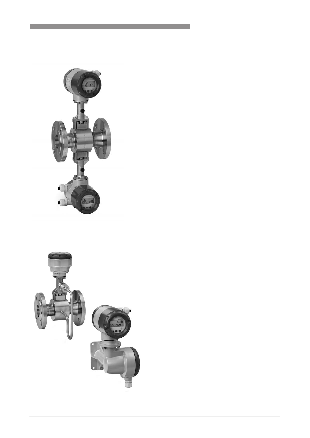
1.1 The all-in-one solution
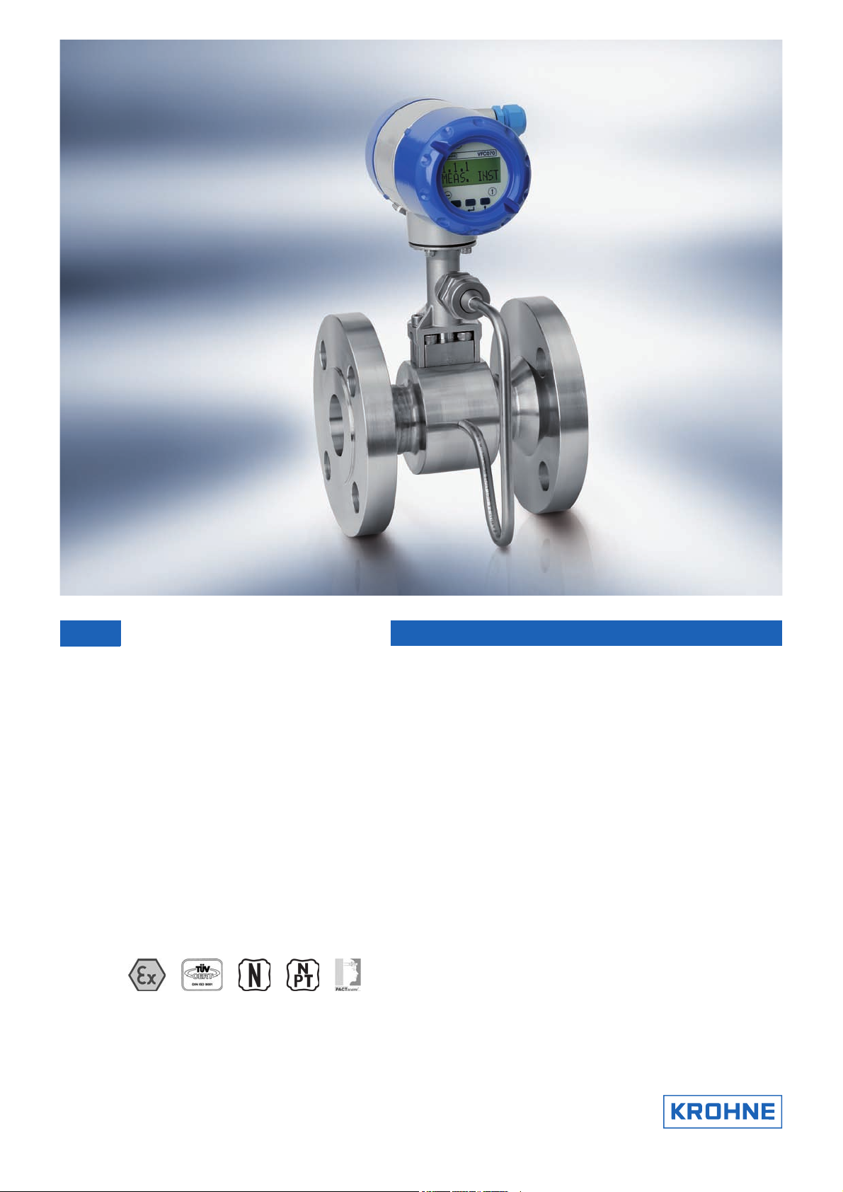
The OPTISWIRL 4070 C
OPTISWIRL 4070 C is the first vortex flowmeter to feature integrated pressure and
OPTISWIRL 4070 COPTISWIRL 4070 C
temperature compensation in 2-wire technology. The OPTISWIRL 4070 C
measurement of operating, standard volumetric and mass flow of conductive and nonconductive liquids, gases and vapours, even with fluctuating pressures and temperatures.
PRODUCT FEATURES
OPTISWIRL 4070 C provides reliable
OPTISWIRL 4070 COPTISWIRL 4070 C
1
1 Pressure sensor
2 Shut-off valve
3 Fully welded stainless steel design
4 Converter with Intelligent Signal Processing [ISP]
www.krohne.com05/2015 - 4000165506 TD OPTISWIRL4070C R08 en
3

1
PRODUCT FEATURES
Highlights
• 2-wire device with integrated pressure and temperature compensation
• Non-wearing, fully welded stainless steel construction with high corrosion, pressure and
temperature resistance
• Optimal process reliability thanks to Intelligent Signal Processing (ISP) - stable readings,
free of external perturbations
• Ready to use immediately thanks to plug & play
• Maintenance-free measuring sensor design
• PACTware available at no extra cost
• Pressure and temperature available via HART
Industries
• Chemicals
• Oil & Gas
• Power plants
• Food & Beverage
• Pharmaceuticals
• Iron, Steel and Metals
• Paper and pulp
• Water
• Automobile industry
OPTISWIRL 4070
Applications
• Vapour and saturated steam measurement
• Steam boiler monitoring
• Monitoring of compressor output
• Measurement of consumption in compressed air systems
• Measurement of consumption of industrial gases
• SIP and CIP processes in the food, beverage and pharmaceutical industries
• Measurement of conductive and non-conductive liquids
4
www.krohne.com 05/2015 - 4000165506 TD OPTISWIRL4070C R08 en
OPTISWIRL 4070
PRODUCT FEATURES
1.2 Options and variants
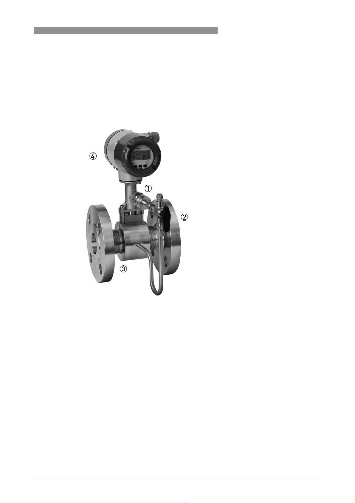
1. The universal device with temperature compensation for saturated steam integrated as
standard
The OPTISWIRL 4070
OPTISWIRL 4070 as a compact flowmeter in a
OPTISWIRL 4070OPTISWIRL 4070
flange version is suitable for universal use in measuring
liquids, gases and vapours.
The temperature compensation for saturated steam is
integrated as standard, thus enabling direct
compensation of the density; the mass and energy can
also be measured.
Here ISP (Intelligent Signal Processing) provides stable
measurement results free of external perturbations.
1
2. The easy to install sandwich version with optimised centring rings
The OPTISWIRL 4070
OPTISWIRL 4070 as a compact flowmeter in a
OPTISWIRL 4070OPTISWIRL 4070
sandwich version is suitable for universal use in the
measurement of liquids, gases and vapours. The
temperature compensation for saturated steam is
integrated as standard.
The flowmeter is provided with additional optimised
centring rings. The OPTISWIRL can be aligned
centrically by turning the centring rings, eliminating any
offset between the OPTISWIRL and the pipeline.
www.krohne.com05/2015 - 4000165506 TD OPTISWIRL4070C R08 en
5
1
PRODUCT FEATURES
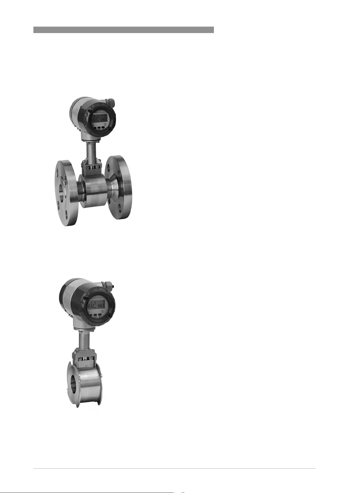
3. The only 2-wire device with integrated pressure and temperature compensation
The OPTISWIRL 4070
OPTISWIRL 4070 as a flange or sandwich flowmeter
OPTISWIRL 4070OPTISWIRL 4070
is optionally available with integrated pressure and
temperature compensation for gases, wet gases, gas
mixtures or vapours. The advantages of this unique
design couldn't be clearer:
• No additional cost-intensive installation of pressure
and temperature sensors
• No additional cabling work
• No faulty measurement results, because pressure,
temperature and volume flow can be read at a single
point
• Direct measurement of mass and/or energy
OPTISWIRL 4070
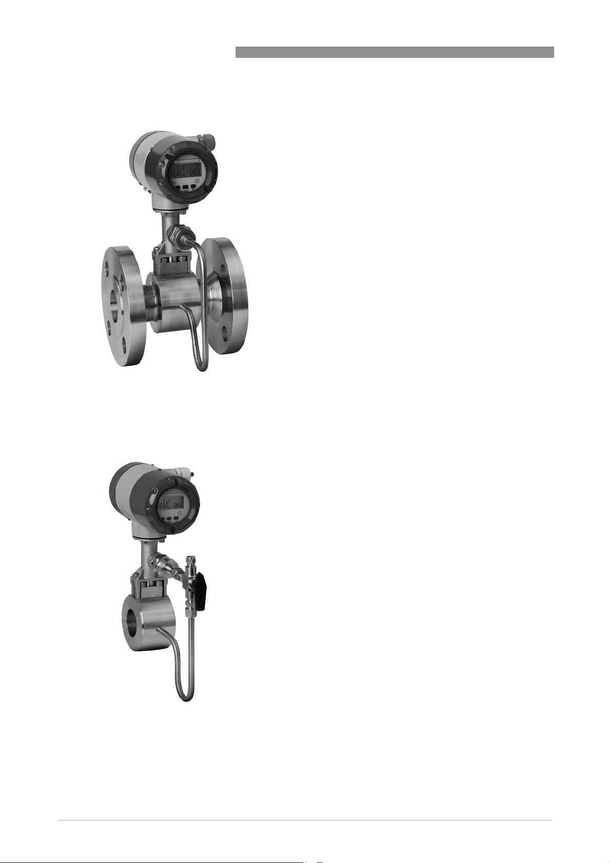
4. The highest process availability thanks to optional shut-off valve
As an option, the OPTISWIRL 4070
a shut-off valve to allow the pressure sensor to be
exchanged without interrupting the process.
What is more, the pressure sensor can be shut off for
the purpose of pressure or leak testing of the pipeline.
Using the built-in two-way valve, the pressure sensor
can also be calibrated and tested at a later time.
OPTISWIRL 4070 can be supplied with
OPTISWIRL 4070OPTISWIRL 4070
6
www.krohne.com 05/2015 - 4000165506 TD OPTISWIRL4070C R08 en
OPTISWIRL 4070
5. Dual measurement for twofold reliability
PRODUCT FEATURES
The OPTISWIRL 4070
OPTISWIRL 4070 is optionally available as a dual
OPTISWIRL 4070OPTISWIRL 4070
version.
This is a genuine redundant system with two
independent measuring sensors and two signal
converters. This provides twofold functional reliability
and availability of the measurement.
This variant is ideally suited for measurements in multiproduct pipelines. In such pipelines, two different
products are moved through one after the other.
One signal converter can be programmed for one
product, and the other signal converter for the other
product.
1
6. OPTISWIRL 4070 F – Field housing (remote version)
The OPTISWIRL 4070
OPTISWIRL 4070 is also available as a remote
OPTISWIRL 4070OPTISWIRL 4070
version with a field housing converter.
This feature allows separating the signal converter
from the measuring sensor up to a distance
of 15 m / 49 ft in case the measuring sensor is mounted
in inaccessible areas. The remote mounted signal
converter allows easy operation and reading of values
at eye level.
Additionally to the flow rates, measurements of the
integrated pressure and temperature sensors can be
displayed.
www.krohne.com05/2015 - 4000165506 TD OPTISWIRL4070C R08 en
7
1
PRODUCT FEATURES
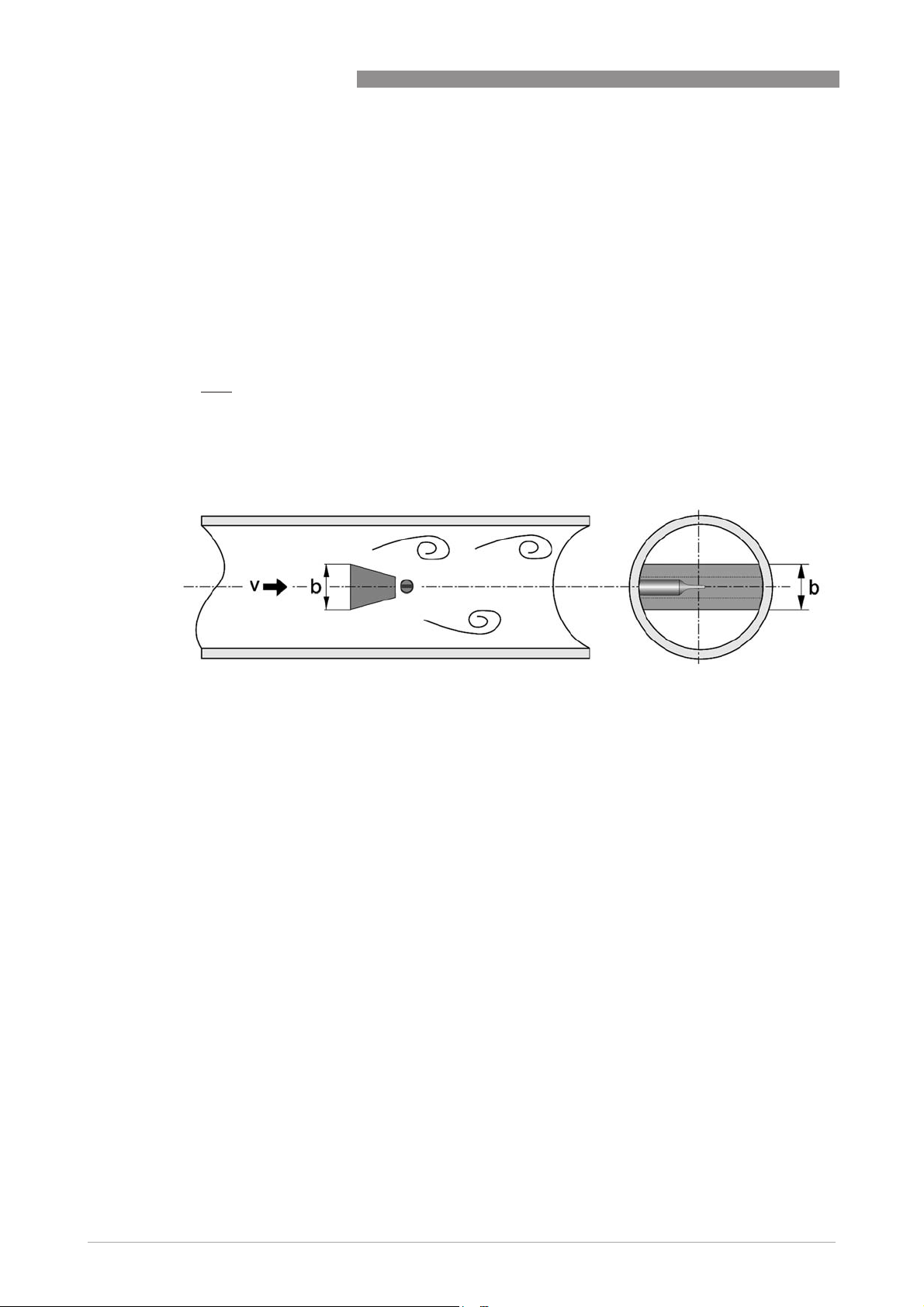
1.3 Functional principle
Vortex flowmeters are used to measure the volumetric flow of gases, vapours and liquids at
completely filled pipes. The measuring principle is based on the Karman vortex street. The
measuring tube contains a bluff body, behind which vortex shedding occurs. The frequency ffff of
the vortex shedding is proportional to the flow velocity vvvv. The non-dimensional Stouhal number SSSS
describes
the relationship between vortex frequency ffff, width bbbb of the bluff body and the mean flow velocity
vvvv:
S.v
f
=
b
The vortex frequency is recorded at the sensor and evaluated at the converter.
OPTISWIRL 4070
Figure 1-1: Functional principle
8
www.krohne.com 05/2015 - 4000165506 TD OPTISWIRL4070C R08 en

OPTISWIRL 4070
2.1 Technical data
•
The following data is provided for general applications. If you require data that is more
relevant to your specific application, please contact us or your local sales office.
•
Additional information (certificates, special tools, software,...) and complete product
documentation can be downloaded free of charge from the website (Downloadcenter).
Measuring system
Application range Flow measurement of liquids, gases and vapours
Function / Measuring principle Karman vortex street
Measured value
Primary measured value Number of separated vortices
Secondary measured value Operating and standard volume flow, mass flow
Transmitter
Versions Compact
Remote version - cable length ≤ 15m (49 ft)
TECHNICAL DATA
2
Measuring sensor
Standard Flange version (with integrated temperature measurement), Sensor: F
Sandwich version (with integrated temperature measurement), Sensor: S
Option Basic device with additional pressure measurement
Basic device with additional pressure measurement and shut-off valve for pressure
sensor
Dual measuring device in both flange and sandwich version (redundant
measurement)
Dual measuring device in flange version with additional pressure measurement
Flange version with single reduction, measuring sensor: F1R
Flange version with double reduction, measuring sensor: F2R
Display and user interface
Local display 2 rows, 10 characters
Interface and display languages German, English, French
www.krohne.com05/2015 - 4000165506 TD OPTISWIRL4070C R08 en
9

2
TECHNICAL DATA
Measuring accuracy
Reference condition Water at 20°C
Air at 20°C and 1.013 bar abs.
Accuracy Based on volume flow
Liquids ±0.75% of measured value (Re ≥ 20000)
±2.0% of measured value (10000 < Re < 20000)
Gases and vapours ±1.0% of measured value (Re ≥ 20000)
±2.0% of measured value (10000 < Re < 20000)
Pressure and temperature compensation: ±1.5% of measured value (Re ≥ 20000);
±2.5% of measured value (10000 < Re < 20000)
Repeatability ±0.1% of measured value
Long term stability ±0.01% of measured value
Operating conditions
Temperature
Product -40…+240°C / -40…+465°F
Ambient Non-Ex: -40…+85°C / -40…+185°F
Ex: -40...+60°C / -40...+140°F
Storage -50…+85°C / -58…+185°F
OPTISWIRL 4070
Pressure
Product Max. 100 bar / 1450 psi; Information on higher pressures on request.
Ambient Atmosphere
Media properties
Density Taken into consideration when sizing.
Viscosity < 10 cP
Reynold's number 10000...2300000
Recommended flow velocities
Liquids 0.3…7 m/s / 0.98…23 ft/s (optional up to 10 m/s / 32.8 ft/s taking cavitation into
Gases and vapours 2.0…80 m/s / 6.6…262.5 ft/s
account)
DN15: 3.0…45 m/s / 9.8…148 ft/s; DN25: 2.0…70 m/s / 6.6…230 ft/s
For detailed information, refer to chapter "Flow tables".
Other conditions
Ingress protection IP 66/67
10
www.krohne.com 05/2015 - 4000165506 TD OPTISWIRL4070C R08 en

OPTISWIRL 4070
TECHNICAL DATA
Installation conditions
Inlet section ≥ 20 x DN (without disturbing flow, after pipe narrowing, after a single 90° bend)
≥ 30 x DN (after a double bend 2x90°)
≥ 40 x DN (after a double three-dimensional bend 2x90°)
≥ 50 x DN (after control valves)
≥ 2 DN before flow straightener; ≥ 8 DN after flow straightener (specified values
apply only to original ≥ 20 DN inlet run)
Outlet section ≥ 5 x DN
Dimensions and weights See chapter "Dimensions and weights"
Materials
Measuring sensor and process
connections
Electronics housing Die-cast aluminium
Pressure sensor gasket Standard: FPM
Measuring tube gasket Standard: 1.4435/316L
Standard: 1.4404/316L
Option: Hastelloy® C-22 on request
Option: FFKM
2
Option: Hastelloy® C-276
Selection depends on measuring sensor material/medium.
Process connections of flange version
DIN EN 1092-1 DN15...300 in PN16…100
ASME B16.5 ½...12" in 150…600 lb
JIS B 2220 DN15...300 in JIS 10…20 K
For detailed information on combination flange/pressure rating, refer to section
"Dimensions and weights".
Process connections of sandwich version
DIN DN15...100 in PN100 (higher pressures on request)
ASME ½...4" in 600 lb (higher pressures on request)
JIS DN15...100 in 10…20 K (higher pressures on request)
Electrical connections
Power supply Non-Ex: 14…36 VDC
Ex: 14…30 VDC
Current Output
Description of abbreviations U
Measuring range
Load Minimum 0 Ω; maximum RL = ((U
Error signal Acc. to NAMUR NE43
= external voltage; RL = load + resistance
ext
4...20 mA (max. 20.8 mA) + HART® protocol
- 14 VDC) / 22 mA)
ext
Upper value: ≥ 21.0 mA
Lower value: ≤ 3.6 mA (not with HART® protocol)
www.krohne.com05/2015 - 4000165506 TD OPTISWIRL4070C R08 en
11
 Loading...