

Page 1
Supplementary instructions
Supplementary instructions
OPTISONIC 3400
OPTISONIC 3400
OPTISONIC 3400OPTISONIC 3400
Supplementary instructions Supplementary instructions
Ultrasonic flow meter
Addendum for hazardous area. These additional instructions are an extension to the
OPTISONIC 3400 manual and quick start.
© KROHNE 10/2013 - 7312472200 - AD EX OPTISONIC 3400 -en- R02
Page 2

CONTENTS
OPTISONIC 3400
1 Introduction 4
1.1 Safety instructions from the manufacturer ..................................................................... 4
1.1.1 Copyright and data protection ................................................................................................ 4
1.1.2 Disclaimer ............................................................................................................................... 4
1.1.3 Product liability and warranty ................................................................................................ 5
1.1.4 Information concerning the documentation........................................................................... 5
1.1.5 Warnings and symbols used................................................................................................... 6
1.1.6 Manufacturer .......................................................................................................................... 7
1.2 Safety instructions for the operator................................................................................. 7
1.3 Approval............................................................................................................................ 7
1.4 OPTISONIC 3400 C(/i)-Ex.................................................................................................. 8
1.5 OPTISONIC 3000 F/...-Ex .................................................................................................. 8
1.6 UFC 400 F(/i)-Ex ............................................................................................................... 9
1.7 Marking labels (examples) ............................................................................................. 10
1.7.1 I/O sticker............................................................................................................................. 12
1.7.2 Nameplate for the measuring sensor (field version)........................................................... 12
2 Temperature limits 14
2.1 General ........................................................................................................................... 14
2.2 UFC 400 F(/i)-Ex ............................................................................................................. 14
2.3 OPTISONIC 3400 C(/i)-Ex................................................................................................ 14
2.4 OPTISONIC 3000 F/...-Ex ................................................................................................ 15
3 Connection of separate systems 16
3.1 General ........................................................................................................................... 16
3.2 Cable marking ................................................................................................................ 16
3.3 Cable parameters...........................................................................................................16
3.4 Equipotential bonding..................................................................................................... 17
3.4.1 Signal converter.................................................................................................................... 17
3.5 Signal cable connections (filed versions)....................................................................... 17
4 Electrical connections 19
4.1 General ........................................................................................................................... 19
4.2 Cable glands ................................................................................................................... 21
4.3 Field Wiring..................................................................................................................... 21
4.4 Non-"Ex i" I/O connections............................................................................................. 22
4.5 "Ex i" I/O connections .....................................................................................................24
5 Maintenance and service 26
5.1 Maintenance ................................................................................................................... 26
5.2 Before and after opening................................................................................................ 26
5.3 Replacement of mains fuse............................................................................................ 27
5.4 Exchange of electronics unit .......................................................................................... 28
5.4.1 Field version.......................................................................................................................... 29
2
www.krohne.com 10/2013 - 7312472200 - AD EX OPTISONIC 3400 -en- R02
Page 3

OPTISONIC 3400
CONTENTS
5.5 Service / repair information ........................................................................................... 31
5.6 Form (for copying) to accompany a returned device ..................................................... 32
5.7 Disposal .......................................................................................................................... 32
6 Notes 33
www.krohne.com10/2013 - 7312472200 - AD EX OPTISONIC 3400 -en- R02
3
Page 4

1 INTRODUCTION
1.1 Safety instructions from the manufacturer
1.1.1 Copyright and data protection
The contents of this document have been created with great care. Nevertheless, we provide no
guarantee that the contents are correct, complete or up-to-date.
The contents and works in this document are subject to copyright. Contributions from third
parties are identified as such. Reproduction, processing, dissemination and any type of use
beyond what is permitted under copyright requires written authorisation from the respective
author and/or the manufacturer.
The manufacturer tries always to observe the copyrights of others, and to draw on works created
in-house or works in the public domain.
The collection of personal data (such as names, street addresses or e-mail addresses) in the
manufacturer's documents is always on a voluntary basis whenever possible. Whenever
feasible, it is always possible to make use of the offerings and services without providing any
personal data.
OPTISONIC 3400
We draw your attention to the fact that data transmission over the Internet (e.g. when
communicating by e-mail) may involve gaps in security. It is not possible to protect such data
completely against access by third parties.
We hereby expressly prohibit the use of the contact data published as part of our duty to publish
an imprint for the purpose of sending us any advertising or informational materials that we have
not expressly requested.
1.1.2 Disclaimer
The manufacturer will not be liable for any damage of any kind by using its product, including,
but not limited to direct, indirect or incidental and consequential damages.
This disclaimer does not apply in case the manufacturer has acted on purpose or with gross
negligence. In the event any applicable law does not allow such limitations on implied warranties
or the exclusion of limitation of certain damages, you may, if such law applies to you, not be
subject to some or all of the above disclaimer, exclusions or limitations.
Any product purchased from the manufacturer is warranted in accordance with the relevant
product documentation and our Terms and Conditions of Sale.
The manufacturer reserves the right to alter the content of its documents, including this
disclaimer in any way, at any time, for any reason, without prior notification, and will not be liable
in any way for possible consequences of such changes.
4
www.krohne.com 10/2013 - 7312472200 - AD EX OPTISONIC 3400 -en- R02
Page 5

OPTISONIC 3400
1.1.3 Product liability and warranty
The operator shall bear responsibility for the suitability of the device for the specific purpose.
The manufacturer accepts no liability for the consequences of misuse by the operator. Improper
installation and operation of the devices (systems) will cause the warranty to be void. The
respective "Standard Terms and Conditions" which form the basis for the sales contract shall
also apply.
1.1.4 Information concerning the documentation
To prevent any injury to the user or damage to the device it is essential that you read the
information in this document and observe applicable national standards, safety requirements
and accident prevention regulations.
If this document is not in your native language and if you have any problems understanding the
text, we advise you to contact your local office for assistance. The manufacturer can not accept
responsibility for any damage or injury caused by misunderstanding of the information in this
document.
This document is provided to help you establish operating conditions, which will permit safe and
efficient use of this device. Special considerations and precautions are also described in the
document, which appear in the form of underneath icons.
INTRODUCTION 1
www.krohne.com10/2013 - 7312472200 - AD EX OPTISONIC 3400 -en- R02
5
Page 6
1 INTRODUCTION
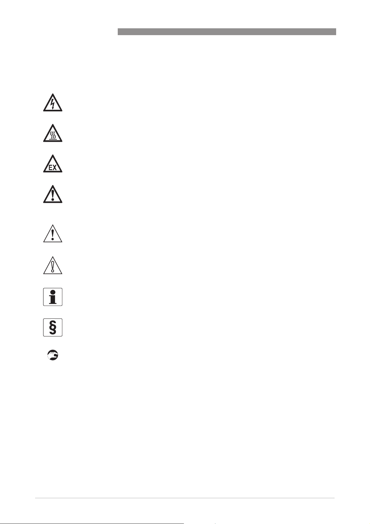
1.1.5 Warnings and symbols used
Safety warnings are indicated by the following symbols.
DANGER!
This information refers to the immediate danger when working with electricity.
DANGER!
This warning refers to the immediate danger of burns caused by heat or hot surfaces.
DANGER!
This warning refers to the immediate danger when using this device in a hazardous atmosphere.
DANGER!
These warnings must be observed without fail. Even partial disregard of this warning can lead to
serious health problems and even death. There is also the risk of seriously damaging the device
or parts of the operator's plant.
OPTISONIC 3400
WARNING!
Disregarding this safety warning, even if only in part, poses the risk of serious health problems.
There is also the risk of damaging the device or parts of the operator's plant.
CAUTION!
Disregarding these instructions can result in damage to the device or to parts of the operator's
plant.
INFORMATION!
These instructions contain important information for the handling of the device.
LEGAL NOTICE!
This note contains information on statutory directives and standards.
• HANDLING
HANDLING
HANDLINGHANDLING
This symbol designates all instructions for actions to be carried out by the operator in the
specified sequence.
i RESULT
RESULT
RESULTRESULT
This symbol refers to all important consequences of the previous actions.
6
www.krohne.com 10/2013 - 7312472200 - AD EX OPTISONIC 3400 -en- R02
Page 7

OPTISONIC 3400
1.1.6 Manufacturer
The instrument is developed and manufactured by:
KROHNE Altometer
Kerkeplaat 12
3313 LC Dordrecht
The Netherlands
For information, maintenance or service please contact your nearest local KROHNE
representative.
1.2 Safety instructions for the operator
WARNING!
•
Do not change the device. Unauthorized changes affect the explosion safety of the devices.
•
The prescriptions and regulations as well as the electrical data described in the EC type
examination certificate must be obeyed.
•
Beside the instructions for electrical installations in non-hazardous locations according to
the applicable national standard (equivalent to HD 384 or IEC 364, e.g. VDE 0100), especially
the regulations in EN 60079-14 "Electrical installations in hazardous locations" or equivalent
national standard (e.g. DIN VDE 0165 Part 1) must be strictly followed.
•
Installation, establishment, utilization and maintenance are only allowed to be executed by
personnel with an education in explosion safety!
INTRODUCTION 1
These additional instructions are an extension to the installation and operating instructions and
only apply to the Ex- versions of the OPTISONIC 3400 C, OPTISONIC 3000 F/... and UFC 400 F(/i)
ultrasonic flowmeters. All technical information as described in the Installation and Operating
Instructions is applicable, when not specifically excluded, completed or replaced by the
instructions in these additional instructions.
1.3 Approval
The OPTISONIC 3400 ultrasonic flowmeters are manufactured according to the European
Directive 94/9 EC (ATEX 100a) and IECEx 02 Certification System. The flowmeters are approved
for installation and use in hazardous classified locations of Zone 1 and 2 and are in accordance
with the European Standards of the IEC/EN 60079 series.The flowmeters are approved for
installation and use in hazardous classified locations of Class I, II and III, Division 1 or Division 2.
They have approval number:
DEKRA 13ATEX0092 X - IECEx DEK 13.0023X
DEKRA 13ATEX0092 X - IECEx DEK 13.0023X
DEKRA 13ATEX0092 X - IECEx DEK 13.0023XDEKRA 13ATEX0092 X - IECEx DEK 13.0023X
INFORMATION!
If you need the EC type approval certificate, please download it from our website.
www.krohne.com10/2013 - 7312472200 - AD EX OPTISONIC 3400 -en- R02
7
Page 8

1 INTRODUCTION
1.4 OPTISONIC 3400 C(/i)-Ex
The OPTISONIC 3400 C(/i)-Ex is the compact configuration of the UFC 400 ultrasonic signal
converter and the OPTISONIC 3000 ultrasonic flow sensor. It provides the ultrasonic transducers
in the flow sensor with intrinsically safe (Ex ia) signals; which are only internal circuits. The flow
converter is provided with increased safety (Ex e) or intrinsically safe (Ex ia) in-/outputs,
indicated by an "i" in the type name and listed as OPTISONIC 3400 C/i- Ex.
The in-/outputs and mains supply connections are located in the terminal compartment, which
can either be ordered as “Ex e” (default) or “Ex d” (optional). The explosion safety marking is as
follows:
OPTISONIC 3400 C-Ex;
“Ex d
Ex d” terminal compartment
terminal compartment “Ex e
Ex dEx d
terminal compartment terminal compartment
II 2 G Ex d [ia] IIC T6...T3 Gb II 2 G Ex d e [ia] IIC T6...T3 Gb
OPTISONIC 3400 C/i-Ex;
“Ex d
Ex d” terminal compartment
terminal compartment “Ex e
Ex dEx d
terminal compartment terminal compartment
II 2(1) G Ex d [ia] [ia Ga] IIC T6...T3 Gb II 2(1) G Ex d e [ia] [ia Ga] IIC T6...T3 Gb
OPTISONIC 3400
Ex e” terminal compartment
terminal compartment
Ex eEx e
terminal compartment terminal compartment
Ex e” terminal compartment
terminal compartment
Ex eEx e
terminal compartment terminal compartment
1.5 OPTISONIC 3000 F/...-Ex
The OPTISONIC 3000 F/...-Ex is the remote (field) configuration of the ultrasonic flow sensor and
has intrinsically safe transducer circuits. It is available in 4 versions as follows,
• Cryogenic: low temperature (LT) versions, suitable for process temperatures of -200...+180°C
/ -328...+356°F
• Standard versions: for process temperature of -45...+180°C / -58...+356°F
• Extra extended versions: (XXT) for process temperatures of -45...+250°C / -58...+482°F.
• High Viscosity versions (HV): for process temperatures of -45...+180°C / -58...+356°F
The normal and XXT-versions are also available as flow sensors, equiped with a closed steel
circuit for hot medium (e.g. steam or hot oil), which is called heating jacket (HJ). The maximum
temperature of the heating medium never exceeds the maximum permissible process
temperature of 180°C (356°F) for the standard versions and 250°C (482°F) for the XXT version.
The flow sensor equipped with a heating jacket, ensures stable process temperatures.
Marking for the different flow sensor types, are listed below.
OPTISONIC 3000 F-Ex & 3000 F/HJ-Ex
OPTISONIC 3000 F-Ex & 3000 F/HJ-Ex
OPTISONIC 3000 F-Ex & 3000 F/HJ-ExOPTISONIC 3000 F-Ex & 3000 F/HJ-Ex
OPTISONIC 3000 F/LT-Ex
OPTISONIC 3000 F/LT-Ex
OPTISONIC 3000 F/LT-ExOPTISONIC 3000 F/LT-Ex
II 2 G Ex ia IIC T6...T3 Gb II 2 G Ex ia IIC T6...T2 Gb
The intrinsically safe (Ex ia) transducer circuits of the OPTISONIC 3000 F/...-Ex are connected to
an associated device and have the following maximum values:
OPTISONIC 3000 F/XXT-Ex
OPTISONIC 3000 F/XXT-Ex
OPTISONIC 3000 F/XXT-ExOPTISONIC 3000 F/XXT-Ex
OPTISONIC 3000 F/XXT/HJ-Ex
OPTISONIC 3000 F/XXT/HJ-Ex
OPTISONIC 3000 F/XXT/HJ-ExOPTISONIC 3000 F/XXT/HJ-Ex
Ui = 13,1 V Ii = 600 mA Ci = 11,6 nF L
= 134 µH
i
INFORMATION!
When thermally insulating the ultrasonic flow sensor, make sure that the temperature of
°
the connection box does not exceed 90
8
C (194°F).
www.krohne.com 10/2013 - 7312472200 - AD EX OPTISONIC 3400 -en- R02
Page 9

OPTISONIC 3400
1.6 UFC 400 F(/i)-Ex
The UFC 400 F(/i)-Ex is the remote (field) configuration of the ultrasonic signal converter and has
intrinsically safe (Ex ia) connections to the ultrasonic flow sensor in remote design. The
ultrasonic signal converter is either provided with increased safety (Ex e) or intrinsically safe (Ex
ia) signal in-/outputs indicated by an "i" in the type name as UFC 400 F/i-Ex The in-/outputs and
mains supply connections are located in the terminal compartment, which can either be
configured as “Ex e” (default) or “Ex d” (optional).
The explosion safety marking is as follows:
UFC 400 F-Ex;
“Ex d
Ex d” terminal compartment
Ex dEx d
II 2 G Ex d [ia] IIC T6 Gb II 2 G Ex d e [ia] IIC T6 Gb
UFC 400 F/i-Ex;
“Ex d
Ex d” terminal compartment
Ex dEx d
II 2(1) G Ex d [ia] [ia Ga] IIC T6 Gb II 2(1) G Ex d e [ia] [ia Ga] IIC T6 Gb
terminal compartment “Ex e
terminal compartment terminal compartment
terminal compartment “Ex e
terminal compartment terminal compartment
Ex e” terminal compartment
Ex eEx e
Ex e” terminal compartment
Ex eEx e
INTRODUCTION 1
terminal compartment
terminal compartment terminal compartment
terminal compartment
terminal compartment terminal compartment
The intrinsically safe transducer output connections have the following values:
Uo = 8,2 V Io = 210 mA Po = 435 mW Co = 1,3 μF or 0,8 μF Lo = 0,5 mH or 1,2 mH
www.krohne.com10/2013 - 7312472200 - AD EX OPTISONIC 3400 -en- R02
9
Page 10
1 INTRODUCTION
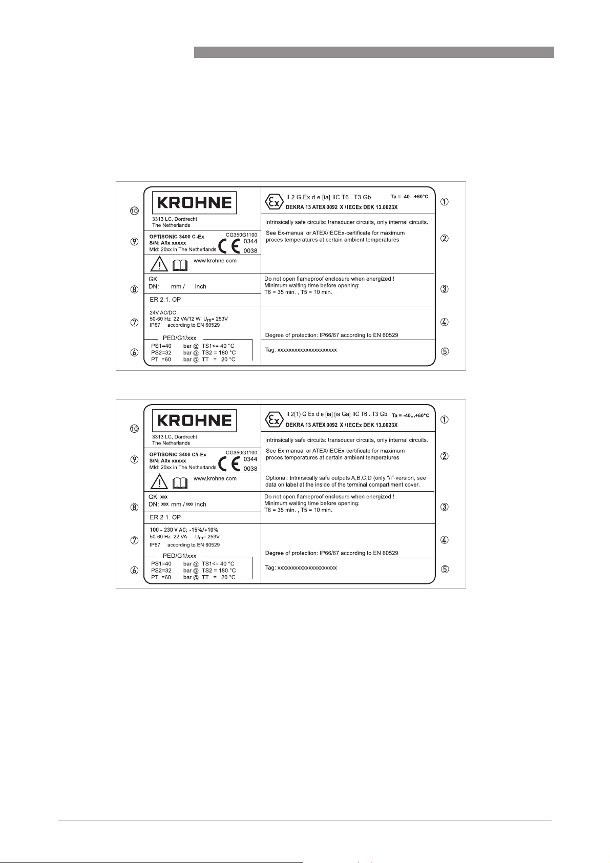
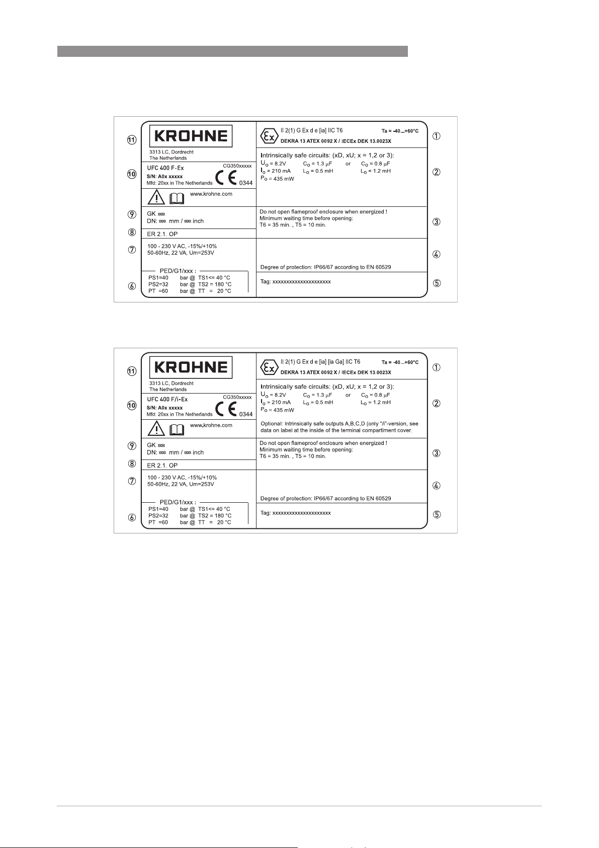
1.7 Marking labels (examples)
See the marking labels (i.e. data stickers) below of respectively OPTISONIC 3400 C(/i)-Ex
ultrasonic compact flowmeter, UFC 400 F(/i)-Ex ultrasonic signal converter in field design,
OPTISONIC 3000 F-Ex ultrasonic flow sensor in field design and extended temperature flow
sensor type OPTISONIC 3000 F/XXT-Ex.
OPTISONIC 3400
Figure 1-1: OPTISONIC 3400 C-Ex data sticker
Figure 1-2: OPTISONIC 3400 C/i-Ex data sticker
1. Ex
2. Marking ATEX / IECEx & Certificate numbers / Ambient temperature
3. Ex specific remarks
4. Ex specific warnings
5. Protection class
6. Tag no.
7. PED data, type I / II / II or SEP
8. Mains supply data
9. Calibration data / Size info and Electronic Revision no.
10. Type designation of the flowmeter and CE sign with number(s) of notified body / bodies
11. Name and address of the manufacturer
10
www.krohne.com 10/2013 - 7312472200 - AD EX OPTISONIC 3400 -en- R02
Page 11
OPTISONIC 3400
Figure 1-3: UFC 400 F-Ex data sticker
INTRODUCTION 1
Figure 1-4: UFC 400 F/i-Ex data sticker
1. Marking ATEX / IECEx & Certificate numbers / Ambient temperature
2. Circuit info
3. Ex specific remarks
4. Protection class
5. Tag no.
6. PED data, type I / II / II or SEP
7. Mains supply data
8. Electronic Revision number
9. Calibration data / Size info
10. Type designation of the flowmeter and CE sign with number(s) of notified body / bodies
11. Name and address of the manufacturer
www.krohne.com10/2013 - 7312472200 - AD EX OPTISONIC 3400 -en- R02
11
Page 12

1 INTRODUCTION
1.7.1 I/O sticker
Figure 1-5: I/O sticker on cover of terminal compartment
OPTISONIC 3400
Example of I/O sticker on the inside of the terminal compartment for modules;
• Fieldbus IO PA on IO board 1.
• Intrinsic safety option with current out active
• Pulse/Status Out/Control in on IO board 2
Other combinations are possible. See the approval description of the UFC 400 electronics unit
1.7.2 Nameplate for the measuring sensor (field version)
Examples for measuring sensor versions in HJ and XXT version.
12
Figure 1-6: Nameplate for the measuring sensor (field version)
www.krohne.com 10/2013 - 7312472200 - AD EX OPTISONIC 3400 -en- R02
Page 13

OPTISONIC 3400
Figure 1-7: Nameplate for the measuring sensor (field version)
INTRODUCTION 1
Figure 1-8: Nameplate for the measuring sensor (field version)
Figure 1-9: Nameplate for the measuring sensor (field version)
1. Specific sign for explosion protection, Ex codes and number of EC type examination certificate
2. Explosion safety notes
3. Tag number
4. PED data, type I / II / II or SEP
5. Calibration data
6. Type designation of the flowmeter and CE sign with number(s) of notified body / bodies
7. Name and address of the manufacturer
www.krohne.com10/2013 - 7312472200 - AD EX OPTISONIC 3400 -en- R02
13
Page 14

2 TEMPERATURE LIMITS
2.1 General
Due to the influence of the process medium temperature (and heating temperature for HJversions), ultrasonic flow sensors in field design with type designation OPTISONIC 3000 F/..Ex
and ultrasonic compact flowmeters with type designation OPTISONIC 3400 C(/i)- Ex are not
allocated to any fixed temperature class. See the temperature classification tables on the
following page for more details. The temperature limits apply under the following conditions:
• The device is installed and operated in accordance with the installation directions given in the
manual.
• The device is not heated up by any additional heat radiation (direct solar radiation, heat from
adjacent plant parts) so causing it to operate above the permissible ambient temperature
range.
• Insulation is not hindering free ventilation of the ultrasonic signal converter housing.
2.2 UFC 400 F(/i)-Ex
The UFC 400 F/…-Ex flow converter in remote design is suitable for ambient temperatures in
the range -40 to +65°C when equipped with basic I/O and -40 to +60°C for all other I/O
configurations.
The surface temperature always remains below 80°C. The flow converter in
remote design is not influenced by the process temperature, because it is installed on a
distance of the remote flow sensor. It therefore has a temperature rating of T6.
OPTISONIC 3400
2.3 OPTISONIC 3400 C(/i)-Ex
The OPTISONIC 3400 C/…-Ex compact flowmeter is suitable for ambient temperatures in
the range of -40...65°C, when equipped with basic I/O, and suitable for an ambient temperature
range of -40…60°C for all the other I/O configurations.
The following temperature limitations should be maintained for the compact flowmeter with
aluminum MH 300 housing and basic I/O.
Temperature classification OPTISONIC 3400 C-.. with aluminum MH 300 housing and
basic I/O.
Temperature class
Temperature class Maximum process temperature [
Temperature classTemperature class
T6 80 80 80 40
T5 95 95 95 40
T4 130 130 95 40
T3 180 145 95 40
Temperature classification OPTISONIC 3400 C/i-.. with aluminum MH 300 housing and
all other I/O configurations.
Temperature class
Temperature class Maximum process temperature [
Temperature classTemperature class
T6 80 80 75 25
T5 95 95 75 25
T4 130 130 75 25
T3 180 130 75 25
Maximum process temperature [ºC] at ...
Maximum process temperature [Maximum process temperature [
Ta
Ta ≤ 50
50ºC
Ta Ta
50 50
Maximum process temperature [ºC] at ...
Maximum process temperature [Maximum process temperature [
Ta
Ta ≤ 45
45ºC
Ta Ta
45 45
C Ta
C C
C Ta
C C
Ta ≤ 55
Ta Ta
Ta ≤ 50
Ta Ta
C] at ...
C] at ...C] at ...
55ºC
C Ta
55 55
CC
C] at ...
C] at ...C] at ...
50ºC
C Ta
50 50
CC
Ta ≤ 60
60ºC
Ta Ta
60 60
Ta ≤ 55
55ºC
Ta Ta
55 55
C Ta
CC
C Ta
CC
Ta ≤ 65
Ta Ta
Ta ≤ 60
Ta Ta
65ºC
C
65 65
C C
60ºC
C
60 60
C C
14
www.krohne.com 10/2013 - 7312472200 - AD EX OPTISONIC 3400 -en- R02
Page 15

OPTISONIC 3400
Temperature classification OPTISONIC 3400 C-.. with stainless steel MH 300 housing
and basic I/O.
Temperatur
Temperatur
TemperaturTemperatur
e class
e class
e classe class
Temperature classification OPTISONIC 3400 C/i-.. with stainless steel MH 300 housing
and all other I/O configurations.
Temperatur
Temperatur
TemperaturTemperatur
e class
e class
e classe class
TEMPERATURE LIMITS 2
Maximum process temperature [
Maximum process temperature [ºC] at ...
Maximum process temperature [Maximum process temperature [
Ta
Ta ≤40
40ºC
C Ta
Ta Ta
4040
C C
T6 80 80 80 80 65 30
T5 95 95 95 95 65 30
T4 130 130 130 105 65 30
T3 180 175 140 105 65 30
Maximum process temperature [
Maximum process temperature [ºC] at ...
Maximum process temperature [Maximum process temperature [
Ta
Ta ≤40
40ºC
C Ta
Ta Ta
4040
C C
T6 80 80 80 45 10
T5 95 95 80 45 10
T4 130 120 80 45 10
T3 155 120 80 45 10
Ta ≤ 45
45ºC
Ta Ta
45 45
Ta ≤ 45
45ºC
Ta Ta
45 45
C Ta
CC
C Ta
CC
C] at ...
C] at ...C] at ...
Ta ≤ 50
50ºC
Ta Ta
50 50
C] at ...
C] at ...C] at ...
Ta ≤ 50
50ºC
Ta Ta
50 50
C Ta
Ta ≤ 55
CC
Ta Ta
C Ta
Ta ≤ 55
CC
Ta Ta
55ºC
C Ta
55 55
CC
55ºC
C Ta
55 55
CC
Ta ≤ 60
60ºC
Ta Ta
60 60
Ta ≤ 60
60ºC
Ta Ta
60 60
C Ta
Ta ≤ 65
C C
Ta Ta
C
C C
65ºC
65 65
C
C C
2.4 OPTISONIC 3000 F/...-Ex
All the OPTISONIC 3000 F /...-Ex ultrasonic flow sensors in field version, are designed for an
ambient temperature range of -40..+70°C.
The tables below shows the temperature classifications.
Temperature classification OPTISONIC 3000 F/… (default & LT / XXT).
Temperature class
Temperature class Maximum process temperature [
Temperature classTemperature class
T6 80 80
T5 95 95
T4 130 130
T3 180 195
T2 n.a. 250
Temperature classification OPTISONIC 3000 F/…/HJ-... (with heating jacket).
Temperature class
Temperature class Maximum process (& heating for HJ) temperature [
Temperature classTemperature class
T6 80 80
T5 95 95
T4 130 130
T3 180 195
T2 n.a. 250
Maximum process temperature [ºC] at T
Maximum process temperature [Maximum process temperature [
OPTISONIC 3000 F-... &
OPTISONIC 3000 F-... &
OPTISONIC 3000 F-... & OPTISONIC 3000 F-... &
Cryogenic versions (LT)
Cryogenic versions (LT)
Cryogenic versions (LT)Cryogenic versions (LT)
Maximum process (& heating for HJ) temperature [ºC] at T
Maximum process (& heating for HJ) temperature [Maximum process (& heating for HJ) temperature [
OPTISONIC 3000 F/HJ-...
OPTISONIC 3000 F/HJ-... OPTISONIC 3000 F/XXT/HJ-...
OPTISONIC 3000 F/HJ-...OPTISONIC 3000 F/HJ-...
C] at T
= 70ºC
C] at TC] at T
aaaa
OPTISONIC 3000 F & Extended
OPTISONIC 3000 F & Extended
OPTISONIC 3000 F & Extended OPTISONIC 3000 F & Extended
temperature versions (XXT)
temperature versions (XXT)
temperature versions (XXT)temperature versions (XXT)
C] at T
= 70ºC
C] at TC] at T
aaaa
OPTISONIC 3000 F/XXT/HJ-...
OPTISONIC 3000 F/XXT/HJ-...OPTISONIC 3000 F/XXT/HJ-...
www.krohne.com10/2013 - 7312472200 - AD EX OPTISONIC 3400 -en- R02
15
Page 16

3 CONNECTION OF SEPARATE SYSTEMS
3.1 General
In the case of separate systems, the electrical connection between OPTISONIC 3000 F/...-Ex
ultrasonic flow sensor and UFC 400 F...-Ex ultrasonic signal converter is established via a signal
cable of type MR06-RG316. This cable consists of six coaxial cables surrounded by an additional
screen and outer insulation layer. The ends of the coaxial cables are provided with SMB plugs.
The signal cable is included with the field system by KROHNE.
3.2 Cable marking
The SMB plugs of the coaxial cables are marked by yellow tubing with a black number of
subsequently 1.1, 1.2, 2.1, 2.2, 3.1 and 3.2. The first number represents the path 1, 2 or 3 and the
second the transducer of that path (1 or 2). The marking of the SMB counter-plugs in the
connection box of the signal converter is respectively 1.1, 1.2, 2.1, 2.2, 3.1 and 3.2. Also refer to
Signal cable connections (filed versions)
box types.
on page 17 for the connection of the several connection
3.3 Cable parameters
The maximum permitted total capacitance and inductance for the connecting cable is:
OPTISONIC 3400
; 1.29 μF or 0.79 μF
C
L
; 0.37 mH or 1.07 mH
L
L
The cable supplied by the manufacturer has the following parameters:
distributed capacitance C
distributed inductance L
(core/screen) = 94 pF/m
C
(core/screen) = 0.24 μH/m
C
INFORMATION!
The standard length of the signal cable is 5 m / 16.4 ft. In case a longer length is required, please
contact your local representative for detailed information.
INFORMATION!
More than 30 m signal cable length is not recommendable, it will have a negative effect on the
measuring accuracy.
16
www.krohne.com 10/2013 - 7312472200 - AD EX OPTISONIC 3400 -en- R02
Page 17

OPTISONIC 3400
3.4 Equipotential bonding
3.4.1 Signal converter
CONNECTION OF SEPARATE SYSTEMS 3
The UFC 400 F...-Ex ultrasonic signal converter must always
equipotential bonding system of the installation in the hazardous classified location. For this
purpose it must be connected to the external U-clamp screw terminal (size M5) of the UFC 400 F
converter.
The separate bonding conductor must be at least 4 mm
it is mechanically protected, see Clause 413 of HD 384.4.41 or IEC 364-4-41. Make sure that the
core of the bonding wire is properly mounted under the U-clamp of the PE-terminal and that the
screw is tightly fixed.
The intrinsically safe transducer circuits of the UFC 400 F signal converter are galvanically
isolated from earth, therefore an equipotential bonding conductor between the flow sensor
(grounded intrinsically safe transducer circuits) and the signal converter (floating-intrinsically
safe transducer circuits) does not have to be connected, but can be used if desired.
must always be incorporated within the
must alwaysmust always
CAUTION!
°
When the ambient temperatures exceed 60
C / 140°F, the cables and cable gland used (for
connection of the UFC 400F/...) must be suitable for of at least 75
3.5 Signal cable connections (filed versions)
See the pictures below for details.
2
(11 AWG) or 2.5 mm2 (14 AWG), in case
°
C / 167°F.
Electrical connection - Standard version
Figure 3-1: Connect the cables in the connection box of the flow sensor
www.krohne.com10/2013 - 7312472200 - AD EX OPTISONIC 3400 -en- R02
17
Page 18

3 CONNECTION OF SEPARATE SYSTEMS
Connection of flow sensor type Cryogenic and XXT
Figure 3-2: Connect the cables in the connection box of the flow sensor
OPTISONIC 3400
Figure 3-3: Construction of field version
1 Signal converter
2 Open connection box
3 Tool for releasing connectors
4 Marking on cable
5 Insert cable(s) into terminal compartment
18
www.krohne.com 10/2013 - 7312472200 - AD EX OPTISONIC 3400 -en- R02
Page 19

OPTISONIC 3400
4.1 General
The OPTISONIC 3400 C(/i) -Ex compact flowmeter and UFC 400 F(/i) -Ex signal converter
(separate version) must be incorporated in the equipotential bonding system of the installation.
This can be established internally by connection of the protective earth (PE) conductor of the
mains supply system to the internal PE clamp, or externally, by connecting a separate
equipotential bonding conductor to the external U-clamp terminal (size M5) at respectively the
flange of the mounting support (in case of compact instruments) or at the mounting device (for
signal converters in separate version). A separate bonding conductor must have a cross-
sectional area of at least 4 mm
The display cover seals the electronics compartment of the converter housing and provides type
of protection “flameproof enclosure”. The terminal compartment is default in type of protection
“increased safety” ("Ex e") and can optionally be performed as flameproof enclosure ("Ex d").
The threaded joints formed by the covers and housing are a tight fit due to the requirements for
type of protection “flameproof enclosure”. Screw the covers on and off with care and never use
excessive force !
Keep the screw-threads free of dirt and well-greased (e.g. with PTFE grease). The grease will
help to prevent the threads from locking due to corrosion.
To unscrew the covers, first release the interlocking devices (one at each cover). Therefore
unscrew the M4 head screw with internal hexagon socket set using a No. 3 Allen key until the
interlocking device can be turned. After the covers are screwed back onto the housing, make
sure that the interlocking devices are properly refitted.
ELECTRICAL CONNECTIONS 4
2
.
WARNING!
Allow the electronics to de-energize before opening the electronics compartment of the flow
converter housing. Wait at least 35 minutes for T6 and 10 minutes for T5 before opening.
Figure 4-1: Electrical connections
1 Unscrew interlocking head screw
2 Turn cover counterclockwise and remove
3 Open / close safety lid of mains supply section
4 Mains supply & signal / data terminals
www.krohne.com10/2013 - 7312472200 - AD EX OPTISONIC 3400 -en- R02
19
Page 20

4 ELECTRICAL CONNECTIONS
Figure 4-2: Electrical connections
1 Unscrew interlocking head screw
2 Turn cover counterclockwise and remove
3 Open / close safety lid of mains supply section
4 Mains supply & signal / data terminals
OPTISONIC 3400
Terminals
Terminals Function, electrical data
TerminalsTerminals
L, N
L+, L-
A, A-, A+
B, BC, CD, D-
Function, electrical data
Function, electrical dataFunction, electrical data
Connections for mains supply, always non-Ex i
100...230 V AC, +10%/-15%, 22 VA
12...24 V DC, +30%/-25%, 12 W
24 V AC, +10%/-15%, 22 VA
24 V DC, +30%/-25%, 12 W
Um = 253 V
Connections for signal I/Os (PELV circuits), non-“Ex i” or “Ex i”, are dependent on the
specific version of the UFC 400 converter ordered. Consult the tables with CG35
numbers for details.
The exact I/O-configuration for circuits A, B, C and D is order-specific and can be determined by
the CG35 number shown on the I/O sticker inside the terminal compartment. Therefore check
the data on the back of the UFC 400 electronics unit. The CG35 number contains 10 characters
of which the last three characters (XYZ) determine the configuration of the I/O circuits:
CG35
CG35 **** **** **** XXXX YYYY ZZZZ
CG35CG35
Pos 1...4 5 6 7 8 9 10
determine I/O circuits
For schematic overviews of the CG35 numbers, refer to
and refer to
"Ex i" I/O connections
on page 24. These overviews do not show all details. The exact
Non-"Ex i" I/O connections
on page 22
connection diagram of a specific UFC 400 signal converter can be found on the sticker inside the
terminal compartment.
20
www.krohne.com 10/2013 - 7312472200 - AD EX OPTISONIC 3400 -en- R02
Page 21

OPTISONIC 3400
4.2 Cable glands
The three cable entry holes in the MH-300-... housing have a M20x1.5 screw thread. Make sure
that the custom selected cable glands and/or stopping plugs have the same screw thread.
For use in gaseous hazardous areas:
For use in gaseous hazardous areas: the chosen cable glands and/or stopping plugs, must have
For use in gaseous hazardous areas:For use in gaseous hazardous areas:
the appropriate type of protection for the terminal compartment that is increased safety (Ex e) or
flameproof enclosure (Ex d). They MUST be suitable for the conditions of use and correctly
installed.
The flowmeter with the terminal compartment in type of protection increased safety “Ex e” is
factory supplied with two “Ex e” approved cable glands and one “Ex e” approved blanking element
(i.e. stopping plug).
WARNING!
When the terminal compartment performed as flameproof enclosure
housing is supplied with one
temporary plugs are only intended for sealing the housing against entry of dust, moisture or else
during transport, handling and storage. These temporary plugs must be replaced by suitable
”
approved cable glands, stopping plugs or conduit adapters with sealing devices before the
d
flowmeter is put into operation. Unused openings must be sealed by suitable certified plugs.
ELECTRICAL CONNECTIONS 4
“
Ex d”, the MH 300-..
“
Ex d” approved stopping plug and two temporary plugs. The
“
Ex
4.3 Field Wiring
The wiring of instruments has to be in accordance with the requirements as specified in the
relevant national or international standard for electrical installations in hazardous areas, e.g.
EN 60079-14. Section 9 (wiring systems) of this standard applies to all types of protection.
Section 10 (additional requirements for type of protection “d” - flameproof enclosures), section
11 (additional requirements for type of protection “e” - increased safety) and section 12
(additional requirements for type of protection “i” - intrinsic safety) apply to respectively “Ex d”,
“Ex e” and “Ex i” performed connection (terminal) compartments.
www.krohne.com10/2013 - 7312472200 - AD EX OPTISONIC 3400 -en- R02
21
Page 22

4 ELECTRICAL CONNECTIONS
4.4 Non-"Ex i" I/O connections
The following non-intrinsically safe I/O (inputs/outputs) are available:
I/O PCB
I/O PCB Input/output functions;
I/O PCBI/O PCB
Basic I/O Current Output, active or passive, with HART
Modular I/O Current Output, active or passive, with HART
Modular carrier with 1 or 2 I/O modules Each module: 1 out of following 3 in-/output functions:
Fieldbus I/O Foundation Fieldbus
RS 485 Modbus Modbus with or without termination
OPTISONIC 3400
Input/output functions;
Input/output functions;Input/output functions;
Un < 32 V DC, In < 100 mA, Um = 253 V
Status Output / Control Input
Status Output
Pulse / Status Output
Pulse / Status Output, active or passive, highC or Namur
Current Output, active or passive
Pulse / Status Output, active or passive, highC or Namur
Control Input, active or passive, highC or Namur
Profibus-PA
Notes:
• The options separated by “/” are software selectable (can be changed by the user).
• The options separated by “or” are hardware versions (must be ordered as such).
• All outputs are passive unless otherwise indicated.
• HighC means High Current input/output, Namur means that the in-/outputs are according to
the NAMUR NE43 standard.
22
www.krohne.com 10/2013 - 7312472200 - AD EX OPTISONIC 3400 -en- R02
Page 23

OPTISONIC 3400
Overview of the possible combinations, defined by characters XYZ of the CG35 number
Overview of the possible combinations, defined by characters XYZ of the CG35 number
Overview of the possible combinations, defined by characters XYZ of the CG35 numberOverview of the possible combinations, defined by characters XYZ of the CG35 number
Characters XYZ
Characters XYZ Name of I/O
Characters XYZCharacters XYZ
100 Basic I/O CO
488 to 4LL
588 to 5LL
688 to 6LL
788 to 7LL
888 to 8LL
A88 to ALL
B88 to BLL
C88 to CLL
D88 Fieldbus I/O
D8A to DLL Fieldbus I/O
E88 Fieldbus I/O
E8A to ELL Fieldbus I/O
G00 to GLL RS485 Modbus Many combinations possible DP(a) DP(a)
H00 to HLL Modbus with 1
Used abbreviations for in-/output functions: CO = Current Output, PO = Pulse Output, SO = Status Output,
CI = Control Input, PA = Profibus PA, FF = Foundation Fieldbus, RS485 = RS485 Modbus, n.c. = not
connected.
All in-/outputs are passive unless otherwise noted as active with extension (a).
Name of I/O
Name of I/O Name of I/O
circuits
circuits
circuitscircuits
Modular I/O
or
Modular
Carrier with 1
or 2 I/O
modules
Profibus PA
Profibus PA
with Module
Carrier with 1
or 2 I/O
modules
Foundation
Fieldbus
Foundation
Fieldbus with
Module Carrier
with 1 or 2 I/O
modules
or 2 I/O
modules
ELECTRICAL CONNECTIONS 4
Terminals
Terminals
TerminalsTerminals
A, A-, A+
A, A-, A+
A, A-, A+A, A-, A+
CO(a) over A+
Many combinations possible
n.c. n.c. PA PA
Many combinations possible PA PA
n.c. n.c. FF FF
Many combinations possible FF FF
Terminals
Terminals
TerminalsTerminals
B, B-
B, B-
B, B-B, B-
SO/CI SO PO/SO
Terminals
Terminals
TerminalsTerminals
C, C-
C, C-
C, C-C, C-
RS485 RS485
Terminals
Terminals
TerminalsTerminals
D, D-
D, D-
D, D-D, D-
www.krohne.com10/2013 - 7312472200 - AD EX OPTISONIC 3400 -en- R02
23
Page 24

4 ELECTRICAL CONNECTIONS
4.5 "Ex i" I/O connections
The following intrinsically safe I/O connections are available:
I/O PCB
I/O PCB I/O functions
I/O PCBI/O PCB
Ex i I/O Current Output + HART
Ex i Option Current Output
Fieldbus I/O Profibus-PA
I/O functions
I/O functionsI/O functions
communication
Pulse / Status Output
Current Output, active +
HART communication
Pulse / Status Output /
Control Input
Current Output, active
Foundation Fieldbus
OPTISONIC 3400
Ex ia IIC
Ui = 30 V, Ii = 100 mA, Pi = 1,0 W
= 10 nF, Li = negligibly low
C
i
Ex ia IIC
Uo = 21 V, Io = 90 mA, Po = 0,5 W
Lineair characteristics
= 90 nF, Lo = 2,0 mH
C
o
Co = 110 nF, Lo = 0,5 mH
Ex ia IIC
Ui = 30 V, Ii = 100 mA, Pi = 1,0 W
= 10 nF, Li = negligibly low
C
i
Ex ia IIC
= 21 V, Io = 90 mA, Po = 0,5 W
U
o
Lineair characteristics
= 90 nF, Lo = 2,0 mH
C
o
Co = 110 nF, Lo = 0,5 mH
Ex ia IIC
Ui = 24 V, Ii = 380 mA, Pi = 5,32 W
= 5 nF, Li = 10 μH
C
i
Suitable for connection to an intrinsically safe
fieldbus in accordance with the FISCO model.
The I/O circuits titled “Ex i I/O” and “Ex i Option” are always provided with type of protection
Intrinsic Safety (Ex ia). The I/O-circuits “Fieldbus I/O Profibus-PA” as well as “Fieldbus I/O
Foundation Fieldbus” can be provided with type of protection Intrinsic Safety.
Up to a maximum of 4 intrinsically safe (Ex ia) in-/outputs are possible. All intrinsically safe
circuits are galvanically isolated with respect to earth and each other. To avoid summation of
voltages and current, the wiring of these “Ex ia”-circuits must be sufficiently separated, e.g. in
accordance with the requirements of standard EN 60079-14, clause 12.2.
The “Ex ia” in-/outputs may only be connected to other “Ex ia” or “Ex ib” approved devices (e.g.
intrinsically safe isolation amplifiers), even if such devices are installed in a non-hazardous
location !
Connection to non-“Ex i” devices, cancels the “Ex ia” properties of the flowmeter.
Terminals L and N (or L+ and L-) for connection of the mains supply are not available with type of
protection “intrinsic safety”. To achieve the necessary separation distances between the non-I.S.
and I.S.according to EN 60079-11 between the non-”Ex i” and “Ex i” circuits, the mains terminals
are provided with a semi-circular protection cover with a “snap-in” lock. This cover MUST be
closed before establishing the power supply to the converter.
INFORMATION!
“
For flow converters with an
Ex e” terminal compartment,installed in a Division 2, the nonincendive terminal compartment can be opened in an energized state for short periods of time,
to access the intrinsically safe terminals for possible checks. However, the semi-circular
insulation cover over the non-intrinsically safe mains supply terminals L and N (or L+ and L-)
MUST be kept closed.
24
www.krohne.com 10/2013 - 7312472200 - AD EX OPTISONIC 3400 -en- R02
Page 25

OPTISONIC 3400
Overview of possible "Ex ia" in-/outputs, defined by characters XYZ of the CG 35 numbers
Overview of possible "Ex ia" in-/outputs, defined by characters XYZ of the CG 35 numbers
Overview of possible "Ex ia" in-/outputs, defined by characters XYZ of the CG 35 numbersOverview of possible "Ex ia" in-/outputs, defined by characters XYZ of the CG 35 numbers
Characters XYZ
Characters XYZ Name of I/O
Characters XYZCharacters XYZ
200 Ex i I/O n.c. n.c. CO(a) PO/SO
300 n.c. n.c. CO PO/SO
210 Ex i I/O with Ex
220 CO PO/SO/CI CO(a) PO/SO
310 CO(a) PO/SO/CI CO PO/SO
320 CO PO/SO/CI CO PO/SO
D00 Fieldbus I/O
D10 Fieldbus I/O
D20 CO PO/SO/CI PA PA
E00 Fieldbus I/O
E10 Fieldbus I/O
E20 CO PO/SO/CI FF FF
Used abbreviations for in-/output functions: CO = Current Output, PO = Pulse Output, SO = Status Output,
CI = Control Input, PA = Profibus PA, FF = Foundation Fieldbus, n.c. = not connected
All in-outputs are passive unless otherwise noted as active with extension (a).
Name of I/O
Name of I/O Name of I/O
circuits
circuits
circuitscircuits
i Option
Profibus PA
Profibus PA
with Ex i Option
Foundation
Fieldbus
Foundation
Fieldbus
with Ex i Option
ELECTRICAL CONNECTIONS 4
Terminals
Terminals
TerminalsTerminals
A, A-, A+
A, A-, A+
A, A-, A+A, A-, A+
CO(a) PO/SO/CI CO(a) PO/SO
n.c. n.c. PA PA
CO(a) PO/SO/CI PA PA
n.c. n.c. FF FF
CO(a) PO/SO/CI FF FF
Terminals
Terminals
TerminalsTerminals
B, B-
B, B-
B, B-B, B-
Terminals
Terminals
TerminalsTerminals
C, C-
C, C-
C, C-C, C-
Terminals
Terminals
TerminalsTerminals
D, D-
D, D-
D, D-D, D-
www.krohne.com10/2013 - 7312472200 - AD EX OPTISONIC 3400 -en- R02
25
Page 26

5 MAINTENANCE AND SERVICE
5.1 Maintenance
The flowmeters are maintenance free with respect to the flowmetering properties. Within the
scope of periodic inspections required for electrical equipment installed in hazardous areas it is
recommended to check the flameproof converter housing and covers for signs of damage or
corrosion.
For information about the flameproof joints please contact your KROHNE representative.
The four M6 bolts to screw the MH300-Ex housing have a strength of 700N/mm2
5.2 Before and after opening
WARNING!
the following instructions must always be carefully followed, if the housing of the signal
converter has to be opened respectively closed again.
Before opening:
• Make absolutely sure that there is no explosion hazard!
• Make sure that all connecting cables are safely isolated from all external sources!
• Allow the electronics to de-energize before opening the electronics compartment of the
converter housing. Wait at least 35 minutes for T6 and 10 minutes for T5 before opening.
OPTISONIC 3400
When the instructions above are strictly followed, the display cover (includes glass window) of
the electronics compartment may be removed. First unscrew the head screw with internal
hexagon socket set (size M4) of the interlocking device by a No. 3 Allen key, until the cover can
rotate freely.
After opening:
• Before the cover is screwed back onto the housing, the screw-thread must be clean and well-
greased with an acid and resin-free grease, e.g. PTFE grease.
• Screw the cover as tight as possible onto the housing by hand, until it cannot be opened by
hand anymore. Fixate the screw of the interlocking device tight with the No. 3 Allen key.
26
www.krohne.com 10/2013 - 7312472200 - AD EX OPTISONIC 3400 -en- R02
Page 27

OPTISONIC 3400
5.3 Replacement of mains fuse
WARNING!
Before commencing the work, refer to Before and after opening on page 26
follows:
• Pull the display unit of the mounting frame and turn display unit carefully aside.
• Unscrew the two screws size M4 that hold the mounting frame with the electronics unit.
• Carefully pull the mounting frame with electronics unit out of the housing, until the small
printed circuit board with the six soldered coaxial cables can be pulled off of the sensor driver
PC-board. Now carefully remove the unit from the housing, while keeping the small printed
circuit board with coaxial cables down, close to the housing wall.
• The mains fuse is located in a fuse holder at the back-end of the electronics unit on the top
printed circuit board (power supply PCB). The specifications must be as follows:
Fuse type: 5 x 20 mm (H) according to IEC 60127-2/V
Fuse type: 5 x 20 mm (H) according to IEC 60127-2/V
Fuse type: 5 x 20 mm (H) according to IEC 60127-2/VFuse type: 5 x 20 mm (H) according to IEC 60127-2/V
Power supply
Power supply Electrical data
Power supplyPower supply
12...24 V DC 250 V / 2 A 5060200000
24 V AC/DC 250 V / 2 A 5060200000
100...230 V AC 250 V / 0,8 A 5080850000
MAINTENANCE AND SERVICE 5
, then continue as
Electrical data KROHNE part number
Electrical dataElectrical data
KROHNE part number
KROHNE part numberKROHNE part number
WARNING!
Before reassembling the unit, refer to Before and after opening on page 26
• Reassemble the unit in reverse order.
, then:
www.krohne.com10/2013 - 7312472200 - AD EX OPTISONIC 3400 -en- R02
27
Page 28

5 MAINTENANCE AND SERVICE
5.4 Exchange of electronics unit
Important customer specific data should be documented before replacing the UFC 400
electronics unit. Under normal circumstances, the menu settings are stored on the backplane
PC-board that is fixed inside the signal converter housing. When replacing the electronics unit,
this information is automatically loaded into the new unit.
Contact KROHNE if:
• the unit to be replaced is damaged in such a way that the (customer) settings are lost.
• the new electronics unit contains a different (newer) software version that results in data
error messages during start-up.
WARNING!
Before commencing the work, refer to Before and after opening on page 26
follows:
• Pull the display unit of the mounting frame and turn the display unit carefully aside.
• Unscrew the two screws size M4 that hold the mounting frame with the electronics unit.
• Carefully pull the mounting frame with electronics unit out of the converter housing, until the
small printed circuit board with the four (default) or six (optional) soldered coaxial cables can
be pulled off of the sensor driver PC-board (take care not to apply a large force on the circuit
board while removing the connection board from the sensor driver board). Then remove the
complete electronics unit from the housing.
• Check if the new electronics unit is undamaged and meets the same mains voltage
specifications and in-/output properties.
• Carefully insert the new electronics unit until the small PC-board with six soldered coaxial
cables can be clicked upon the sensor driver PC-board. Install the new unit completely into
the housing and screw the two M4 screws. Put the display unit back onto the front of the
mounting frame.
OPTISONIC 3400
, then continue as
WARNING!
Before screwing the display cover back onto the housing, please refer to Before and after
opening on page 26
.
28
www.krohne.com 10/2013 - 7312472200 - AD EX OPTISONIC 3400 -en- R02
Page 29
OPTISONIC 3400
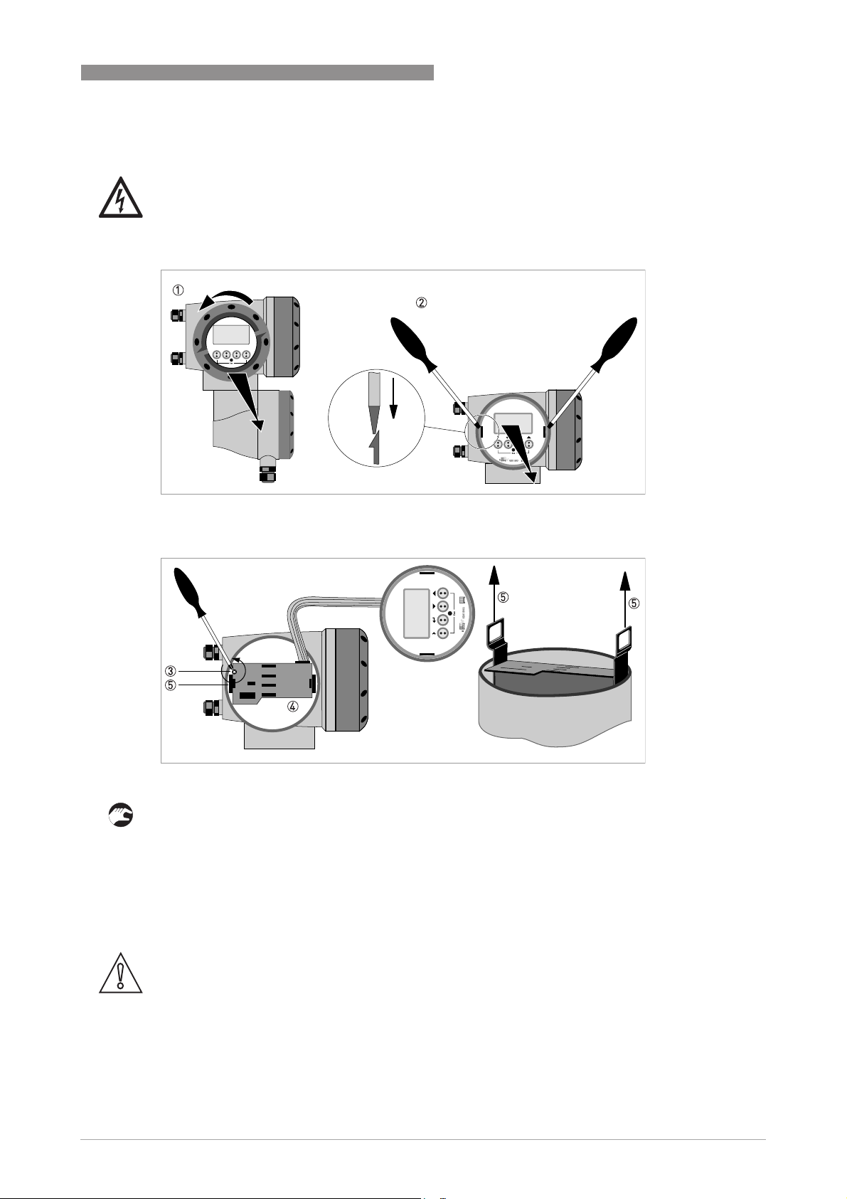
5.4.1 Field version
DANGER!
All work on the electrical connections may only be carried out with the power disconnected. Take
note of the voltage data on the nameplate!
MAINTENANCE AND SERVICE 5
Figure 5-1: Unscrew the cover and remove the display
Figure 5-2: Pull off printed circuit board
Perform the following procedures:
• Unscrew the display cover of the electronics compartment by hand, by turning it counter
clockwise 1.
• Remove the display by using two screwdrivers 2.
• Unscrew the two M4 screws 3 at the electronics unit 4.
• Pull the two metal pullers 5 at the left and right of the display, using a screwdriver or similar
tool and partially pull out the electronics unit.
CAUTION!
Please pay attention that the same amount of force is applied on both pullers, otherwise the
connector at the backside can be damaged.
www.krohne.com10/2013 - 7312472200 - AD EX OPTISONIC 3400 -en- R02
29
Page 30

5 MAINTENANCE AND SERVICE
Figure 5-3: Small printed circuit board and electronics unit
OPTISONIC 3400
DANGER!
Electrostatic discharge (ESD) can damage electronic parts. Make sure to discharge yourself by
wearing a wrist strap. If no wrist strap is available, ground yourself by touching a metal surface
that is grounded.
• Remove the printed circuit board 6 from the electronics unit 4.
• Check compatibility between the removed and new electronics unit 4, by checking the power
voltage.
• Slide the new electronics unit 4 partially back into the housing.
• Mount the small printed circuit board back onto the electronics unit 4.
• Push the metal pullers 5 back to their original position.
Don't use excessive force, otherwise the connector at the backside can be damaged!
• Screw the electronics unit back to the housing.
• Re-install the display and make sure not to kink the display's flat ribbon cable.
• Replace cover and tighten by hand.
• Connect power.
30
www.krohne.com 10/2013 - 7312472200 - AD EX OPTISONIC 3400 -en- R02
Page 31

OPTISONIC 3400
5.5 Service / repair information
This device has been carefully manufactured and tested. If installed and operated in accordance
with these operating instructions, it will rarely present any problems.
CAUTION!
Should you nevertheless need to return a device for inspection or repair, please pay strict
attention to the following points:
•
Due to statutory regulations on environmental protection and safeguarding the health and
safety of our personnel, the manufacturer may only handle, test and repair returned devices
that have been in contact with products without risk to personnel and environment.
•
This means that the manufacturer can only service this device if it is accompanied by the
following certificate (see next section) confirming that the device is safe to handle.
CAUTION!
If the device has been operated with toxic, caustic, flammable or water-endangering products,
you are kindly requested:
•
to check and ensure, if necessary by rinsing or neutralizing, that all cavities are free from
such dangerous substances,
•
to enclose a certificate with the device confirming that is safe to handle and stating the
product used.
MAINTENANCE AND SERVICE 5
www.krohne.com10/2013 - 7312472200 - AD EX OPTISONIC 3400 -en- R02
31
Page 32

5 MAINTENANCE AND SERVICE
5.6 Form (for copying) to accompany a returned device
Company: Address:
Department: Name:
Tel. no.: Fax no.:
Manufacturer's order no. or serial no.:
The device has been operated with the following medium:
OPTISONIC 3400
This medium is: water-hazardous
toxic
caustic
flammable
We checked that all cavities in the device are free from such
substances.
We have flushed out and neutralized all cavities in the
device.
We hereby confirm that there is no risk to persons or the environment through any residual media
contained in the device when it is returned.
Date: Signature:
Stamp:
5.7 Disposal
CAUTION!
Disposal must be carried out in accordance with legislation applicable in your country.
32
www.krohne.com 10/2013 - 7312472200 - AD EX OPTISONIC 3400 -en- R02
Page 33

OPTISONIC 3400
NOTES 6
www.krohne.com10/2013 - 7312472200 - AD EX OPTISONIC 3400 -en- R02
33
Page 34

6 NOTES
OPTISONIC 3400
34
www.krohne.com 10/2013 - 7312472200 - AD EX OPTISONIC 3400 -en- R02
Page 35

OPTISONIC 3400
NOTES 6
www.krohne.com10/2013 - 7312472200 - AD EX OPTISONIC 3400 -en- R02
35
Page 36

KROHNE product overview
• Electromagnetic flowmeters
• Variable area flowmeters
• Ultrasonic flowmeters
• Mass flowmeters
• Vortex flowmeters
• Flow controllers
• Level meters
• Temperature meters
• Pressure meters
• Analysis products
• Products and systems for the oil & gas industry
• Measuring systems for the marine industry
Head Office KROHNE Messtechnik GmbH
Ludwig-Krohne-Str. 5
47058 Duisburg (Germany)
Tel.:+49 (0)203 301 0
Fax:+49 (0)203 301 10389
info@krohne.de
© KROHNE 10/2013 - 7312472200 - AD EX OPTISONIC 3400 -en- R02 - Subject to change without notice.
The current list of all KROHNE contacts and addresses can be found at:
www.krohne.com
 Loading...