

KROHNE OPTIFLUX 6000 Specifications

Technical Datasheet
Technical Datasheet
OPTIFLUX 6000
OPTIFLUX 6000
OPTIFLUX 6000OPTIFLUX 6000
Technical DatasheetTechnical Datasheet
Electromagnetic flow sensor
for hygienic and sanitary applications
•
Robust stainless steel housing for hygienic and aseptic operation
•
Fully suitable for CIP and SIP
•
Typical food & beverage and pharmaceutical process connections and insertion
lengths
The documentation is only complete when used in combination with the relevant
documentation for the signal converter.
© KROHNE 02/2019 - 4000127010 - TD OPTIFLUX 6000 R12 en

CONTENTS
OPTIFLUX 6000
1 Product features 3
1.1 Sanitary and hygienic solution ......................................................................................... 3
1.2 Options.............................................................................................................................. 5
1.3 Measuring principle.......................................................................................................... 7
2 Technical data 8
2.1 Technical data................................................................................................................... 8
2.2 Measuring accuracy ....................................................................................................... 13
2.3 Dimensions and weights ................................................................................................ 15
3 Installation 29
3.1 Intended Use................................................................................................................... 29
3.2 General notes on installation ......................................................................................... 29
3.2.1 Vibration ................................................................................................................................ 29
3.2.2 Magnetic field........................................................................................................................ 29
3.3 Installation conditions ....................................................................................................30
3.3.1 Inlet and outlet...................................................................................................................... 30
3.3.2 Bends in 2 or 3 dimensions................................................................................................... 30
3.3.3 T-section ............................................................................................................................... 31
3.3.4 Bends .................................................................................................................................... 31
3.3.5 Open discharge ..................................................................................................................... 32
3.3.6 Control valve ......................................................................................................................... 32
3.3.7 Pump ..................................................................................................................................... 32
3.3.8 Air venting and vacuum forces ............................................................................................. 33
3.3.9 Mounting requirements for self-draining ............................................................................ 34
3.3.10 Flange deviation .................................................................................................................. 35
3.3.11 Mounting position................................................................................................................ 35
3.4 Mounting......................................................................................................................... 36
3.4.1 Torques and pressures......................................................................................................... 36
3.4.2 Maximum pressures ............................................................................................................. 37
3.4.3 Installation of weld-on versions ........................................................................................... 38
3.4.4 Cleaning ................................................................................................................................ 38
4 Electrical connections 39
4.1 Safety instructions.......................................................................................................... 39
4.2 Grounding ....................................................................................................................... 39
4.3 Virtual reference for IFC 300 ( C, W and F version) ....................................................... 40
4.4 Connection diagrams ..................................................................................................... 40
5 Notes 41
2
www.krohne.com 02/2019 - 4000127010 - TD OPTIFLUX 6000 R12 en

OPTIFLUX 6000
1.1 Sanitary and hygienic solution
The OPTIFLUX 6000
OPTIFLUX 6000 electromagnetic flow sensor is specifically designed to stay clean and
OPTIFLUX 6000OPTIFLUX 6000
sterile in compliance with the most stringent demands prevailing in the food & beverages and
pharmaceutical industries. There are no crevices, gaps or blind spots and the flow sensor offers
full CIP/SIP possibilities. The flow sensor is conform FDA food contact material requirements,
for all wetted materials and is certified in accordance with EHEDG and 3A.
The flowmeter provides easy installation and commissioning and is available with the flow
converter seperate, or mounted directly on the flow sensor.Therefore it can be installed in
places difficult to access due to for example high temperatures or vibrations. The converter is
also available in a stainless steel housing for applications when for example regular cleaning
procedures with aggressive cleaning agents, may attack a standard polyurethane coating.
In addition to weld-end connections, this KROHNE flow meter offers a large number of other
hygienic connections, including DIN 11851, DIN 11864, clamp and SMS.
Because of its high accuracy, a precise measurement of the medium is possible enabling an
accurate measurement of flows whether it is required for blending, dosing or batching.
Furthermore its accuracy is maintained even in case of pulsating flows. When a medium has a
low conductivity for example in case of glucose or fruit concentrates, the device continious to
deliver an optimal performance.
PRODUCT FEATURES
1
Due to its reinforced liner the OPTIFLUX 6000 is an optimal solution for applications where high
temperatures or vacuum impacts can occur. The certified hygienic construction is also available
for larger diameters up to DN150, as volumes are increasing and larger pipe sizes are needed
with fast increase in the industrial production of beer, wine, milk and other beverages.
www.krohne.com02/2019 - 4000127010 - TD OPTIFLUX 6000 R12 en
3

1
PRODUCT FEATURES
Highlights
• Robust stainless steel housing for hygienic and aseptic operation
• PFA liner reinforced with embedded stainless steel grid for vacuum resistance
• High form stability for good accuracy even with high pressures
• Unique L-shaped gasket extends lifetime by preventing protrusion into measurement tube
• Wide choice of the electrode materials, even for extreme chemical applications.
• Simple and effective CIP / SIP
• Typical food and beverages and pharmaceutical process connections and insertion lenghts
• Large diameter range DN2.5 up to DN150, to suit any F&B application
• All wetted materials are conform EC 1935/2004 and FDA food contact material regulation.
• Optimal hygienic performance conforming to EHEDG and 3A certification.
• Able to measure at low conductivity ≥ 1 µS/cm (for demin water ≥ 20 µS/cm)
• Wide process temperature range -40...140°C / -40...+284°F
• PMO certified
Industries
• Food & Beverages
• Pharmaceutical
• Cosmetics
OPTIFLUX 6000
Applications
• Exact blending, dosing and batching
• Beverages including soft drinks, beer, wine and fruits juices
• Milk and other dairy products
• Beverages containing solids (for example yoghurt containing cereals)
• Drugs, caustic sodas, acids, proteins, antibiotics
• CIP media including acids and caustic solutions
• For large-scale production plants with diameter up to DN150
4
www.krohne.com 02/2019 - 4000127010 - TD OPTIFLUX 6000 R12 en
OPTIFLUX 6000
1.2 Options
PRODUCT FEATURES
Reinforced PFA liner
Reinforced PFA liner
Reinforced PFA linerReinforced PFA liner
The OPTIFLUX 6000 has an FDA conform PFA liner
with an integrated stainless steel reinforcement that
ensures vacuum resistance and long-term
dimensional stability. The reinforced PFA liner
makes sure that the flowmeter keeps its form
stability even at high temperatures and very low
pressure or vacuum. Therefore the OPTIFLUX 6000
remains its accuracy over time.
1
Unique gasket adapter concept
Unique gasket adapter concept
Unique gasket adapter conceptUnique gasket adapter concept
A special sealing concept for stainless steel
adapters has been designed with support of TNO, a
member of the European EHEDG organization. The
sealing concept provides for a smooth and
dimensionally stable measuring section between the
two process connections. It prevents the gasket
from expanding into the measuring tube because
during CIP / SIP cleaning procedures, the gasket
expands into an expansion chamber. This leads to a
sharp sealing at the edge of the pipeline and a
perfect transition into the measuring section. In
addition, the gasket experiences less stress which
results in a longer life time and reduced
maintenance.
www.krohne.com02/2019 - 4000127010 - TD OPTIFLUX 6000 R12 en
5

1
PRODUCT FEATURES
OPTIFLUX 6000
Hygienic Converter housing
Hygienic Converter housing
Hygienic Converter housingHygienic Converter housing
The sensor can be complemented with an IFC 100
converter housing made of stainless steel 1.4404.
This stainless steel converter housing for the Food
and Beverage Industry is specially designed to
ensure easy cleanability and resistance to regular
rinsing with detergents
A mounting angle of 10 degrees avoids pooling and
the special EPDM sealing all around, minimises
crevices. Furthermore, the display is made entirely
of polymer and can be used in "no glass" designated
zones.
6
www.krohne.com 02/2019 - 4000127010 - TD OPTIFLUX 6000 R12 en
OPTIFLUX 6000
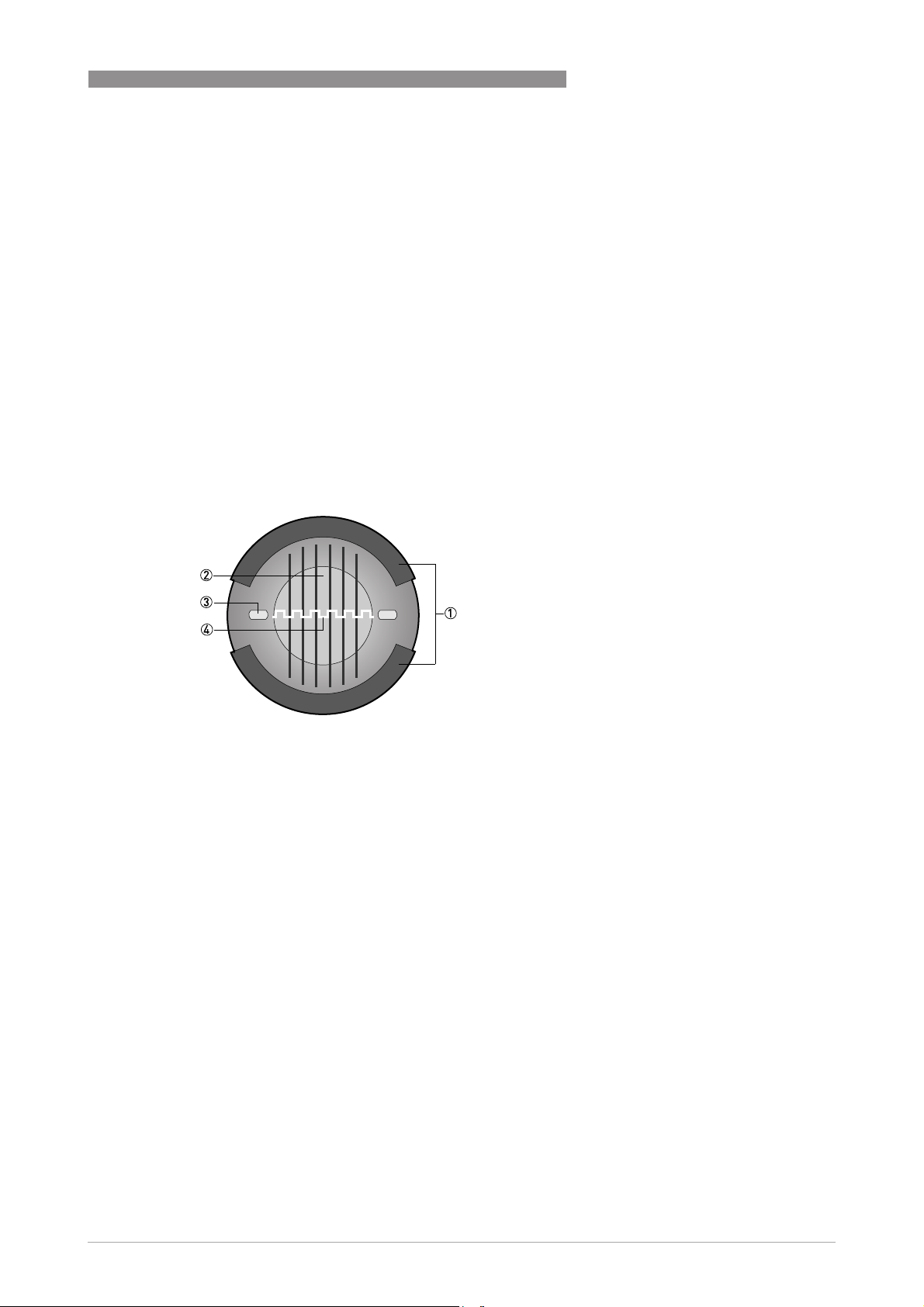
1.3 Measuring principle
An electrically conductive fluid flows inside an electrically insulated pipe through a magnetic
field. This magnetic field is generated by a current, flowing through a pair of field coils.
Inside of the fluid, a voltage U is generated:
U = v * k * B * D
U = v * k * B * D
U = v * k * B * DU = v * k * B * D
in which:
v = mean flow velocity
k = factor correcting for geometry
B = magnetic field strength
D = inner diameter of flowmeter
The signal voltage U is picked off by electrodes and is proportional to the mean flow velocity v
and thus the flow rate Q. A signal converter is used to amplify the signal voltage, filter it and
convert it into signals for totalizing, recording and output processing.
PRODUCT FEATURES
1
Figure 1-1: Measuring principle
1 Field coils
2 Magnetic field
3 Electrodes
4 Induced voltage (proportional to flow velocity)
www.krohne.com02/2019 - 4000127010 - TD OPTIFLUX 6000 R12 en
7

2
TECHNICAL DATA
2.1 Technical data
•
The following data is provided for general applications. If you require data that is more
relevant to your specific application, please contact us or your local sales office.
•
Additional information (certificates, special tools, software,...) and complete product
documentation can be downloaded free of charge from the website (Downloadcenter).
Measuring system
Measuring principle Faraday's law of induction
Application range Electrically conductive fluids
Measured value
Measured value
Measured valueMeasured value
Primary measured
value
Secondary measured
value
Design
Features Hygienic design
Modular construction The measurement system consists of a flow sensor and a signal converter.
Compact version With IFC 050 signal converter: OPTIFLUX 6050 C
Remote version In wall (W) mount version with IFC 050 signal converter: OPTIFLUX 6050 W
Nominal diameter DN2.5...150 / 1/10"...6"
Measuring range -12...+12 m/s / -40...+40 ft/s
OPTIFLUX 6000
Flow velocity
Volume flow
Stainless steel housing
Food & beverage and pharmaceutical process connections
It is available as compact and as separate version.
With IFC 100 signal converter: OPTIFLUX 6100 C
With IFC 300 signal converter: OPTIFLUX 6300 C
In wall (W) mount version with IFC 100signal converter: OPTIFLUX 6100 W
In field (F), wall (W) or rack (R) mount version with IFC 300 signal converter:
OPTIFLUX 6300 F, W or R
8
www.krohne.com 02/2019 - 4000127010 - TD OPTIFLUX 6000 R12 en

OPTIFLUX 6000
Measuring accuracy
Maximum measuring
error
Repeatability ±0.1% of MV, minimum 1 mm/s
Long term stability ±0.1% of MV
Special calibration On request
TECHNICAL DATA
Depending on signal converter and DN size.
IFC 050: down to 0.5% of the measured value ± 1 mm/s.
IFC 100: down to 0.3% of the measured value ± 1 mm/s for DN10...150 (³/8...6").
down to 0.4% of the measured value ± 1 mm/s for DN2.5...6 (¹/10...¼").
IFC 300: down to 0.2% of the measured value ± 1 mm/s for DN10...150 (³/8...6").
down to 0.3% of the measured value ± 2 mm/s for DN2.5...6 (¹/10...¼").
Optional:
Optional:
Optional:Optional:
Optimised accuracy for IFC 050 and IFC 100.
For more details on optimised accuracy, see the concerning signal converter
documentation.
The additional typical measuring deviation for the current output is ±10 µA.
The maximum measuring error depends on the installation conditions.
For detailed information refer to
Measuring accuracy
on page 13.
2
Operating conditions
Temperature
Temperature
TemperatureTemperature
Process temperature Separate flow sensor: -40...+140°C / -40...+284°F
Compact with IFC 300 converter: -40...+140°C / -40...+284°F
Compact with IFC 050 and IFC 100 converter: -40...+120°C / -40...+248°F
at an ambient temperature ≤ 40 °C / 104 °F
For ISO 2852 and Tri-clamp versions: -40...+120°C / -40...+248°F
For Ex versions different temperatures are valid.
Please check the relevant Ex documentation for details.
Ambient temperature -40...+65°C / -40...+149°F
IFC 100 stainless steel version: -40...+60°C / -40...+140°F
Storage temperature -50...+70°C / -58...+158°F
Pressure
Pressure
PressurePressure
Ambient pressure Atmospheric
Nominal flange
pressure
Vacuum load 0 mbar / 0 psi
Chemical properties
Chemical properties
Chemical propertiesChemical properties
Physical condition Electrical conductive liquids
Electrical conductivity Standard: ≥ 1 μS/cm
Permissible gas
content
(volume)
Permissible solid
content
(volume)
For detailed information refer to
Water: ≥ 20 μS/cm
IFC 050: ≤ 3%
IFC 100: ≤ 3%
IFC 300: ≤ 5%
IFC 050: ≤ 10%
IFC 100: ≤ 10%
IFC 300: ≤ 70%
Dimensions and weights
on page 15.
www.krohne.com02/2019 - 4000127010 - TD OPTIFLUX 6000 R12 en
9

2
TECHNICAL DATA
Installation conditions
Installation Assure that the flow sensor is always fully filled.
Flow direction Forward and reverse
Inlet run ≥ 5 DN
Outlet run ≥ 2 DN
Dimensions and
weights
Materials
Sensor housing DN2.5...15: stainless steel Duplex (1.4462)
Measuring tube Stainless steel AISI 304 (1.4301)
Adapters Stainless steel AISI 316 L (1.4404)
Liner PFA
Connection box
(F-version only)
Electrodes Standard:
For detailed information refer to
Arrow on flow sensor indicates positive flow direction.
For detailed information refer to
DN25...150: stainless steel AISI 304 (1.4301)
Other materials on request.
Standard:
Standard:
Standard:Standard:
Aluminum with a standard coating
Option:
Option:
Option:Option:
Stainless steel AISI (1.4408)
Standard:
Standard:Standard:
Installation
on page 29.
Dimensions and weights
OPTIFLUX 6000
on page 15.
Hastelloy® C
Option:
Option:
Option:Option:
Hastelloy® B2, platinum, stainless steel, tantalum, titanium
Gaskets Standard:
Standard:
Standard:Standard:
EPDM
FDA recommends EPDM gaskets only if medium ≤ 8% fat.
Option:
Option:
Option:Option:
Silicone (non-Ex only)
10
www.krohne.com 02/2019 - 4000127010 - TD OPTIFLUX 6000 R12 en

OPTIFLUX 6000
Process connections
DIN 11850 row 2
/ 11866 row A
DIN 11851 DN2.5...150
DIN 11864-2A
flange with notch
DIN 32676 DN25...150
ISO 2037 DN2.5...150
ISO 2852 DN2.5...150
SMS 1146 DN2.5...100
Tri Clamp 1/10"...6"
Note: sensor diameters < DN10 have DN10 connections, which means the sensor diameter is smaller.
Electrical connections
Signal cable
Signal cable
Signal cableSignal cable
Type A (DS) Standard cable, double shielded.
Type B (BTS) Optional cable, triple shielded.
TECHNICAL DATA
DN2.5...150
DN25...150
Max. length: 600 m / 1950 ft (dep. on electrical conductivity and measuring
sensor). See documentation of the converter for more information.
Max. length: 600 m / 1950 ft (dep. on electrical conductivity and measuring
sensor). See documentation of the converter for more information.
2
www.krohne.com02/2019 - 4000127010 - TD OPTIFLUX 6000 R12 en
11

2
TECHNICAL DATA
Approvals and certificates
CE
CE
CECE
This device fulfills the statutory requirements of the EU directives.
The manufacturer certifies successful testing of the product by applying the CE mark.
Hazardous areas
Hazardous areas
Hazardous areasHazardous areas
ATEX Please check the relevant Ex documentation for details.
FM In combination with IFC 300 C or F converter:
CSA In combination with IFC 300 C or F converter:
Other approvals and standards
Other approvals and standards
Other approvals and standardsOther approvals and standards
Protection category acc. to
IEC/EN 60529
Hygienic 3A approved
Shock test IEC 60068-2-27
Vibration test IEC 60068-2-64
OPTIFLUX 6000
For full information of the EU directives and standards and the approved
certifications, please refer to the EU Declaration of Conformity or the
website of the manufacturer.
Compact version with IFC 300 C converter:
Compact version with IFC 300 C converter:
Compact version with IFC 300 C converter:Compact version with IFC 300 C converter:
II 2 G, II D, II 2 (1) G
Remote (F) version:
Remote (F) version:
Remote (F) version:Remote (F) version:
II 2 G, II 2 D
In combination with IFC 300 C or F converter:
In combination with IFC 300 C or F converter:In combination with IFC 300 C or F converter:
Class I, Div. 2, Groups A, B, C and D
Class II, Div. 2, Groups F and G
Class III, Div. 2, Groups F and G
Only available for DN2.5...15
In combination with IFC 300 C or F converter:
In combination with IFC 300 C or F converter:In combination with IFC 300 C or F converter:
Class I, Div. 2, Groups A, B, C and D
Class II, Div. 2, Groups F and G
Class III, Div. 2, Groups F and G
Only available for DN2.5...15
Standard
Standard
StandardStandard
IP 66/67 (NEMA 4/4X/6)
Option (F version only)
Option (F version only)
Option (F version only)Option (F version only)
IP 68 field (NEMA 6P)
IP 68 factory (NEMA 6P)
IP 68 is only available for separate design and with a stainless steel
connection box.
Option IP69
Option IP69
Option IP69Option IP69
IP 67/69 is available for connection box and IFC 100 in stainless steel.
EHEDG
30 g for 18 ms
f = 20...2000 Hz, rms = 4.5 g, t = 30 min.
12
www.krohne.com 02/2019 - 4000127010 - TD OPTIFLUX 6000 R12 en
OPTIFLUX 6000
2.2 Measuring accuracy
Every electromagnetic flowmeter is calibrated by direct volume comparison. The wet calibration
validates the performance of the flowmeter under reference conditions against accuracy limits.
The accuracy limits of electromagnetic flowmeters are typically the result of the combined effect
of linearity, zero point stability and calibration uncertainty.
Reference conditions
• Medium: water
• Temperature: +5...35°C / +41...95°F
• Operating pressure: 0.1...5 barg / 1.5...72.5 psig
• Inlet section: ≥ 5 DN
• Outlet section: ≥ 2 DN
TECHNICAL DATA
2
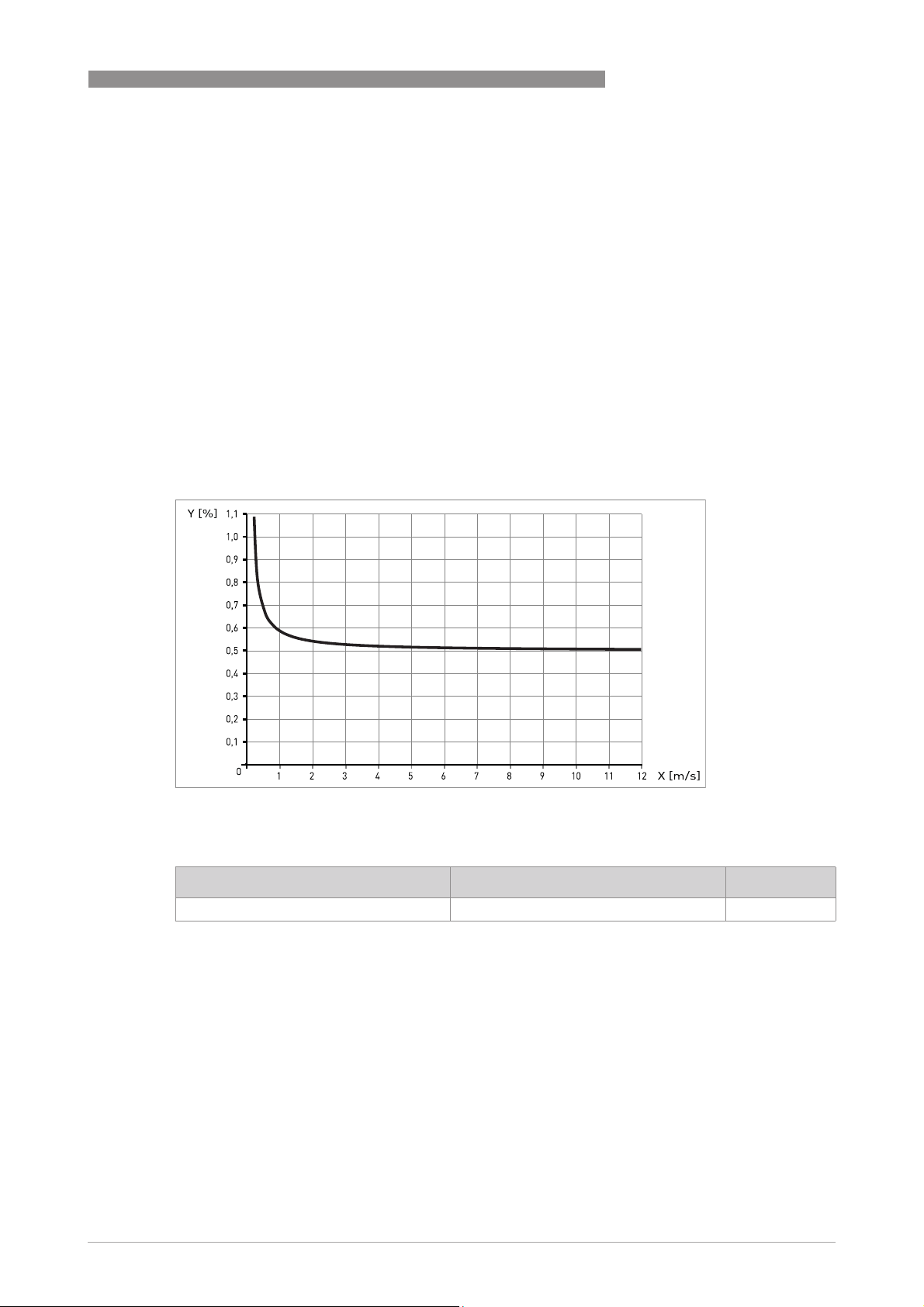
Figure 2-1: Flow velocity vs. accuracy
X [m/s] : flow velocity
Y [%]: deviation from the actual measured value (mv)
Compact with IFC 050 Accuracy Curve
DN10...150 / 3/8...6" 0.5% of MV + 1 mm/s
Optionally for IFC 050; extended calibration at 2 points for optimised accuracy.
For more details on optimised accuracy, see the concerning signal converter documentation.
www.krohne.com02/2019 - 4000127010 - TD OPTIFLUX 6000 R12 en
13
2
TECHNICAL DATA
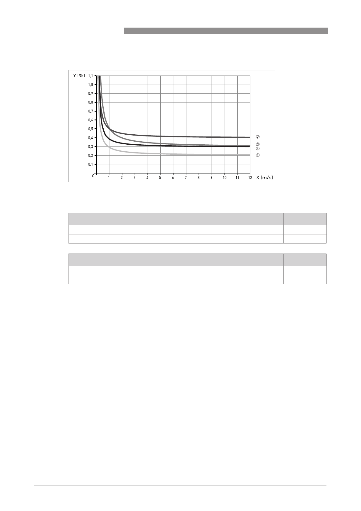
Figure 2-2: Flow velocity vs. accuracy
X [m/s] : flow velocity
Y [%]: deviation from the actual measured value (mv)
OPTIFLUX 6000
Compact with IFC 300 Accuracy Curve
DN2.5...6 / 1/10...1/4" 0.3% of MV + 2 mm/s 3
DN10...150 / 3/8...6" 0.2% of MV + 1 mm/s 1
Compact with IFC 100 Accuracy Curve
DN2.5...6 / 1/10...1/4" 0.4% of MV + 1 mm/s 2
DN10...150 / 3/8...6" 0.3% of MV + 1 mm/s 4
Optionally for IFC 100; extended calibration at 2 points for optimised accuracy.
For more details on optimised accuracy, see the concerning signal converter documentation.
14
www.krohne.com 02/2019 - 4000127010 - TD OPTIFLUX 6000 R12 en
 Loading...