


 BM 26 BASIC/ADVANCED Handbook
Stainless Steel Bypass Level Indicators for applications up to 40 bar / 580 psi
© KROHNE 10/2012 - 4000347004 - HB BM26 Basic/Adv R04 en
:IMPRINT :::::::::::::::::::::::::::::::::::::::
All rights reserved. It is prohibited to reproduce this documentation, or any part thereof, without the prior written authorisation of KROHNE Messtechnik GmbH.
Subject to change without notice.
Copyright 2012 by
KROHNE Messtechnik GmbH - Ludwig-Krohne-Str. 5 - 47058 Duisburg (Germany)
2 |
www.krohne.com |
10/2012 - 4000347004 - HB BM26 Basic/Adv R04 en |

|
|
|
CONTENTS |
|
|
||
|
BM 26 BASIC/ADVANCED |
|
|||||
|
|
|
|
|
|
||
1 |
Safety instructions |
5 |
|
||||
|
|
|
|
|
|
|
|
|
|
|
1.1 |
Intended use ..................................................................................................................... |
5 |
|
|
|
|
|
1.2 |
Certification ...................................................................................................................... |
5 |
|
|
|
|
|
1.3 |
Safety instructions from the manufacturer ..................................................................... |
6 |
|
|
|
|
|
1.3.1 Disclaimer ............................................................................................................................... |
6 |
|
||
|
|
|
1.3.2 Product liability and warranty ................................................................................................ |
7 |
|
||
|
|
|
1.3.3 Information concerning the documentation........................................................................... |
7 |
|
||
|
|
|
1.3.4 Warnings and symbols used................................................................................................... |
8 |
|
||
|
|
|
1.4 |
Safety instructions for the operator................................................................................. |
8 |
|
|
|
|
2 Device description |
9 |
|
|||
|
|
|
|
|
|
||
|
|
|
2.1 |
Scope of delivery............................................................................................................... |
9 |
||
|
|
|
2.2 |
Device description .......................................................................................................... |
10 |
||
|
|
|
2.3 |
Nameplates .................................................................................................................... |
11 |
||
|
|
|
2.3.1 Visual Check.......................................................................................................................... |
11 |
|
||
|
|
|
2.3.2 Nameplates........................................................................................................................... |
11 |
|
||
|
|
|
2.3.3 Other device data .................................................................................................................. |
14 |
|
||
3 |
Installation |
15 |
|
||||
|
|
|
|
|
|
||
|
|
|
3.1 |
Storage ........................................................................................................................... |
15 |
||
|
|
|
3.2 |
Transportation ................................................................................................................ |
16 |
|
|
|
|
|
3.3 |
Remove all packing before installation ......................................................................... |
16 |
||
|
|
|
3.4 |
General requirements .................................................................................................... |
18 |
|
|
|
|
|
3.4.1 Pressure and temperature ranges....................................................................................... |
18 |
|
||
|
|
|
3.4.2 How to attach the bypass level indicator to the tank ........................................................... |
19 |
|
||
|
|
|
3.5 |
Level indicator column................................................................................................... |
21 |
||
|
|
|
3.6 |
Optional analog transmitter ........................................................................................... |
22 |
|
|
|
|
|
3.7 |
Optional limit switch....................................................................................................... |
23 |
||
|
|
|
3.8 |
Electromagnetic compatibility ....................................................................................... |
26 |
|
|
|
|
4 Electrical connections |
27 |
|
|||
|
|
|
|
|
|
|
|
|
|
|
4.1 |
Optional analog transmitter ........................................................................................... |
27 |
|
|
|
|
|
4.2 |
Optional limit switches ................................................................................................... |
29 |
||
|
|
|
4.3 |
Protection category ........................................................................................................ |
30 |
||
|
|
5 Start-up |
31 |
|
|||
|
|
|
|
|
|
||
|
|
|
5.1 |
Start-up checklist........................................................................................................... |
31 |
||
|
|
|
5.2 |
Operating concept .......................................................................................................... |
31 |
||
10/2012 - 4000347004 - HB BM26 Basic/Adv R04 en |
www.krohne.com |
3 |

|
CONTENTS |
BM 26 BASIC/ADVANCED |
|
|
|
||
|
|
|
|
6 Operation |
32 |
|
6.1 |
Local display options ...................................................................................................... |
32 |
6.1.1 Level indicator column ......................................................................................................... |
32 |
|
6.1.2 Analog transmitter (option) .................................................................................................. |
33 |
|
6.2 |
Errors.............................................................................................................................. |
37 |
6.2.1 Error indication ..................................................................................................................... |
37 |
|
6.2.2 Error handling....................................................................................................................... |
38 |
|
7 Service |
41 |
|
7.1 |
Periodic maintenance..................................................................................................... |
41 |
7.2 |
Keep the device clean..................................................................................................... |
41 |
7.3 |
How to replace device components ............................................................................... |
41 |
7.3.1 Service warranty ................................................................................................................... |
41 |
|
7.4 |
Availability of services .................................................................................................... |
42 |
7.4.1 General notes........................................................................................................................ |
42 |
|
7.4.2 List of spare parts................................................................................................................. |
42 |
|
7.4.3 List of accessories ................................................................................................................ |
43 |
|
7.5 |
Availability of services .................................................................................................... |
43 |
7.6 |
Returning the device to the manufacturer..................................................................... |
44 |
7.6.1 General information.............................................................................................................. |
44 |
|
7.6.2 Form (for copying) to accompany a returned device............................................................ |
45 |
|
7.7 |
Disposal .......................................................................................................................... |
45 |
8 Technical data |
46 |
|
8.1 |
Measuring principle........................................................................................................ |
46 |
8.2 |
Technical data: general information.............................................................................. |
47 |
8.3 |
Technical data: optional analog transmitter.................................................................. |
51 |
8.4 |
Technical data: optional limit switches.......................................................................... |
56 |
8.5 |
Basic version: Dimensions and weights ........................................................................ |
58 |
8.6 |
Advanced version: Dimensions and weights.................................................................. |
66 |
8.7 |
Analog transmitter: Dimensions and weight ................................................................. |
74 |
8.8 |
Support bracket option: Dimensions and weight........................................................... |
75 |
8.9 |
Guidelines for maximum operating pressure................................................................ |
76 |
8.10 Floats ............................................................................................................................ |
78 |
|
9 Appendix |
79 |
|
9.1 |
Liquid level offset: description....................................................................................... |
79 |
9.2 |
Liquid level offset: correction data ................................................................................ |
80 |
9.3 |
Glossary .......................................................................................................................... |
83 |
9.4 |
Order code ...................................................................................................................... |
84 |
9.5 |
Spare parts code ............................................................................................................ |
92 |
10 Notes |
94 |
|
4 |
www.krohne.com |
10/2012 - 4000347004 - HB BM26 Basic/Adv R04 en |

|
|
SAFETY INSTRUCTIONS 1 |
|
BM 26 BASIC/ADVANCED |
|
|
|
|
1.1 Intended use
This magnetic level indicator measures the level or volume of liquids.
It is installed next to open or pressurized tanks. With the applicable options, it is resistant to difficult service conditions and liquids that are poisonous, flammable, or that cause corrosion.
CAUTION!
Responsibility for the use of the measuring devices with regard to suitability, intended use and corrosion resistance of the used materials against the measured fluid lies solely with the operator.
INFORMATION!
The manufacturer is not liable for any damage resulting from improper use or use for other than the intended purpose.
1.2 Certification
In accordance with KROHNE’s commitment to customer service and safety, the level indicators described in this handbook meet the following safety requirements:
•EMC Directive 2004/108/EC in conjunction with EN 61326-1: 2006
•Low Voltage Directive 2006/95/EC in conjunction with EN 61010-1: 2001
•Pressure Equipment Directive 97/23/EC in conjunction with CODAP® 2010
INFORMATION!
The optimized design of the Basic version is not subject to PED test requirements (CE marking is not applicable). The Advanced version agrees with the requirements for CE marking.
The Low Voltage Directive is only applicable to limit switches (non-NAMUR option).
10/2012 - 4000347004 - HB BM26 Basic/Adv R04 en |
www.krohne.com |
5 |

1 SAFETY INSTRUCTIONS |
|
|
BM 26 BASIC/ADVANCED |
|
|
|
|
|
1.3 Safety instructions from the manufacturer
1.3.1 Disclaimer
The manufacturer will not be liable for any damage of any kind by using its product, including, but not limited to direct, indirect or incidental and consequential damages.
This disclaimer does not apply in case the manufacturer has acted on purpose or with gross negligence. In the event any applicable law does not allow such limitations on implied warranties or the exclusion of limitation of certain damages, you may, if such law applies to you, not be subject to some or all of the above disclaimer, exclusions or limitations.
Any product purchased from the manufacturer is warranted in accordance with the relevant product documentation and our Terms and Conditions of Sale.
The manufacturer reserves the right to alter the content of its documents, including this disclaimer in any way, at any time, for any reason, without prior notification, and will not be liable in any way for possible consequences of such changes.
6 |
www.krohne.com |
10/2012 - 4000347004 - HB BM26 Basic/Adv R04 en |

|
|
SAFETY INSTRUCTIONS 1 |
|
BM 26 BASIC/ADVANCED |
|
|
|
|
1.3.2 Product liability and warranty
Bypass level indicators from KROHNE are designed solely for measuring the level and volume of liquids.
Responsibility as to suitability and intended use of these level indicators rests solely with the operator. The supplier does not accept any liability resulting from misuse by the operator. Improper installation and operation of the level transmitters may lead to loss of warranty. In addition, the “General conditions of sale“ which forms the basis of the purchase agreement are applicable.
1.3.3 Information concerning the documentation
To prevent any injury to the user or damage to the device it is essential that you read the information in this document and observe applicable national standards, safety requirements and accident prevention regulations.
If this document is not in your native language and if you have any problems understanding the text, we advise you to contact your local office for assistance. The manufacturer can not accept responsibility for any damage or injury caused by misunderstanding of the information in this document.
This document is provided to help you establish operating conditions, which will permit safe and efficient use of this device. Special considerations and precautions are also described in the document, which appear in the form of underneath icons.
10/2012 - 4000347004 - HB BM26 Basic/Adv R04 en |
www.krohne.com |
7 |
1 SAFETY INSTRUCTIONS |
|
|
BM 26 BASIC/ADVANCED |
|
|
|
|
|
1.3.4 Warnings and symbols used
Safety warnings are indicated by the following symbols.
DANGER!
This information refers to the immediate danger when working with electricity.
DANGER!
This warning refers to the immediate danger of burns caused by heat or hot surfaces.
DANGER!
This warning refers to the immediate danger when using this device in a hazardous atmosphere.
DANGER!
These warnings must be observed without fail. Even partial disregard of this warning can lead to serious health problems and even death. There is also the risk of seriously damaging the device or parts of the operator's plant.
WARNING!
Disregarding this safety warning, even if only in part, poses the risk of serious health problems. There is also the risk of damaging the device or parts of the operator's plant.
CAUTION!
Disregarding these instructions can result in damage to the device or to parts of the operator's plant.
INFORMATION!
These instructions contain important information for the handling of the device.
LEGAL NOTICE!
This note contains information on statutory directives and standards.
• HANDLING
This symbol designates all instructions for actions to be carried out by the operator in the specified sequence.
iRESULT
This symbol refers to all important consequences of the previous actions.
1.4Safety instructions for the operator
WARNING!
In general, devices from the manufacturer may only be installed, commissioned, operated and maintained by properly trained and authorized personnel.
This document is provided to help you establish operating conditions, which will permit safe and efficient use of this device.
8 |
www.krohne.com |
10/2012 - 4000347004 - HB BM26 Basic/Adv R04 en |
|
|
DEVICE DESCRIPTION 2 |
|
BM 26 BASIC/ADVANCED |
|
|
|
|
2.1 Scope of delivery
INFORMATION!
Check the packing list to see if you have received all that you require.
The device will be delivered in one box.
INFORMATION!
Inspect the cartons carefully for damages or signs of rough handling. Report damage to the carrier and to the local office of the manufacturer.
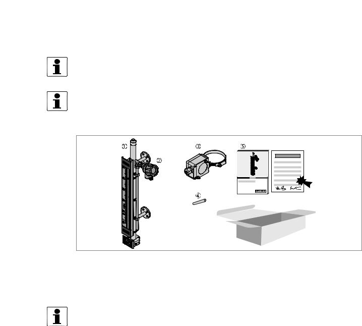
Figure 2-1: Scope of delivery
1Measuring chamber with the indicator column and optional indicator scale
2Optional analog transmitter
3Optional limit switches (not attached to the device)
4Magnet (to set the indicator column to zero after installation)
5Quick Start and Handbook
INFORMATION!
No special tools, no training required!
10/2012 - 4000347004 - HB BM26 Basic/Adv R04 en |
www.krohne.com |
9 |

2 DEVICE DESCRIPTION |
BM 26 BASIC/ADVANCED |
|
2.2 Device description
Magnetic level indicators have a measuring chamber that contains a magnetic float. It is attached vertically to the side of open or pressurized tanks. A level indicator is attached adjacent to the measuring chamber. As the float moves up and down, it rotates a column of flaps inside the glass tube of the indicator. If an analog level transmitter is also attached adjacent to the measuring chamber, it is possible to have an output current that can be monitored from a remote station. Optional bistable switches let the user monitor important measurement limits.
The measuring chamber of the Basic version has a maximum operating pressure of 16 barg / 232 psig (depending on the length of the chamber). It is unnecessary to test the measuring chamber according to PED 97/23/EC as it does not have to comply with CE marking requirements. It is also ideal for measuring liquids with a density ≥0.8 kg/l / ≥49.9 lb/ft³ and temperatures up to 150°C / 300°F.
The Advanced version is ideal for measuring liquids with density range of 0.58...2.0 kg/l / 36.2...124.8 lb/ft³, temperatures up to 300°C / 570°F or pressures up to 40 barg / 580 psig.
WARNING!
Pressure Equipment Directive 97/23/EC data
• This device is designed to function at near constant pressure conditions. It is not designed for operating conditions where vibration or fatigue stress is present.
•Events that are not taken into account in the calculations include exceptional risks such as: earthquakes, bad weather, fire etc.
•The standard design calculation does not take into account the theoretical coefficient of corrosion. The product circulating in the device must not have properties that give rise to surface erosion.
•Our conformity declaration is limited to the parts of the device that are pressurized. It does not include parts that can be dismantled (valves, ...).
You can also order these accessories:
• Limit switches
10 |
www.krohne.com |
10/2012 - 4000347004 - HB BM26 Basic/Adv R04 en |
|
|
DEVICE DESCRIPTION 2 |
|
BM 26 BASIC/ADVANCED |
|
|
|
|
2.3 Nameplates
INFORMATION!
Look at the device nameplate to ensure that the device is delivered according to your order. Check for the correct supply voltage printed on the nameplate.
2.3.1 Visual Check
Figure 2-2: Visual check
• Check the delivery for damage.
•Are all the wetted components (chamber, flanges and gaskets) resistant to the product in the tank?
•Compare the data on the nameplate with your order data.
2.3.2Nameplates
Figure 2-3: Location of device nameplates
1Measuring chamber nameplate
2Analog transmitter nameplate
3Limit switch nameplate (housing cover)
4Limit switch nameplate (housing)
10/2012 - 4000347004 - HB BM26 Basic/Adv R04 en |
www.krohne.com |
11 |

2 DEVICE DESCRIPTION |
BM 26 BASIC/ADVANCED |
|
L |
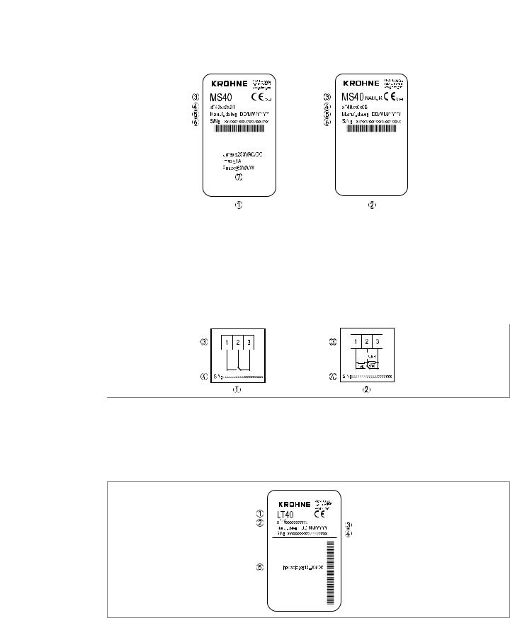
Figure 2-4: Basic version: Non-Ex nameplate
L |
Figure 2-5: Advanced version: Non-Ex nameplate
1Customer tag number
2Measuring tube volume in litres
3Maximum allowable pressure (Ps)
4Factory serial number
5Purchase order number
6Model name and number
7Designation code (VF code given in the order)
8Year of manufacture
9Maximum allowable temperature (Ts)
10Test pressure (Pt at 20°C) - if the device agrees with the requirements of Categories I, II or III of the Pressure Equipment Directive 97/23/EC.
12 |
www.krohne.com |
10/2012 - 4000347004 - HB BM26 Basic/Adv R04 en |
|
|
|
|
|
|
|
|
|
DEVICE DESCRIPTION 2 |
||
|
BM 26 BASIC/ADVANCED |
||||||||||
|
|
|
|
|
|
|
|
|
|
|
|
|
|
|
|
|
|
|
|
|
|
|
|
|
|
|
|
|
|
|
|
|
|
|
|
|
|
|
|
|
|
|
|
|
|
|
|
|
|
|
|
|
|
|
|
|
|
|
|
|
|
|
|
|
|
|
|
|
|
|
|
|
|
|
|
|
|
|
|
|
|
|
|
|
|
|
|
|
|
|
|
|
|
|
|
Figure 2-6: Limit switch: Non-Ex nameplate (housing cover)
1Non-NAMUR option
2NAMUR option
3Model
4Designation code (VF code given in the order)
5Date of manufacture
6Factory serial number and bar code
7Electrical data
Figure 2-7: Limit switch: Non-Ex nameplate (housing)
1Non-NAMUR option
2NAMUR option
3Electrical schema
4Factory serial number
Figure 2-8: Analog transmitter: Non-Ex nameplate
1Model
2Designation code (VF code given in the order)
3Date of manufacture
4Factory serial number
5Input voltage
10/2012 - 4000347004 - HB BM26 Basic/Adv R04 en |
www.krohne.com |
13 |
2 DEVICE DESCRIPTION |
BM 26 BASIC/ADVANCED |
|
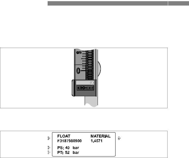
2.3.3 Other device data
The supplier's bottom logo plate has a sticker:
Figure 2-9: Other device data
1 Float data sticker
Figure 2-10: Float data sticker
1Test pressure, PT, in bar
2Maximum allowable pressure, PS, in bar
3Float drawing number
4Float material
14 |
www.krohne.com |
10/2012 - 4000347004 - HB BM26 Basic/Adv R04 en |
|
|
INSTALLATION 3 |
|
BM 26 BASIC/ADVANCED |
|
|
|
|
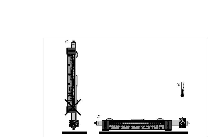
3.1 Storage
Figure 3-1: Storage conditions
1Do not keep the device in a vertical position before installation.
2Put the device on its side.
3Storage temperature range: -50…+80°C / -58…+176°F
•Store the device in a dry and dust-free location.
•Store the device in its original packing.
10/2012 - 4000347004 - HB BM26 Basic/Adv R04 en |
www.krohne.com |
15 |
3 INSTALLATION |
BM 26 BASIC/ADVANCED |
|
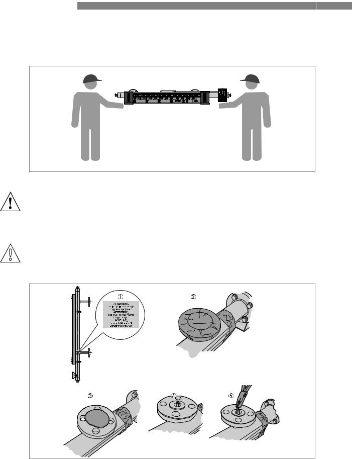
3.2 Transportation
Figure 3-2: Transportation
WARNING!
The indicator column is made of Pyrex® glass.
If you do not lift the device carefully, you can cause damage to the device.
3.3 Remove all packing before installation
CAUTION!
Make sure that the measuring chamber does not contain unwanted objects (dirt etc.)
How to remove the float lock pin (devices with side process connections)
Figure 3-3: How to remove the float lock pin (devices with side process connections)
16 |
www.krohne.com |
10/2012 - 4000347004 - HB BM26 Basic/Adv R04 en |
|
|
INSTALLATION 3 |
|
BM 26 BASIC/ADVANCED |
|
|
|
|
How to remove the float lock pin (devices with side process connections)
1Check the measuring chamber for a red sticker next to the bottom side process connection. i Sticker text: ATTENTION! Take away transport safety device for float.
2Remove the adhesive tape around the top and bottom process connections.
3Remove the plastic protection from the top and bottom process connections.
4Find the lock pin.
5Remove the lock pin with a pair of pliers.
How to put the float in the measuring chamber
Figure 3-4: How to put the float in the measuring chamber (if it is delivered separately)
1Put the float in here
2Float
3The float data (date of manufacture, Ps/Pt, float material etc.) must be at the top of the float when you put the float in the measuring chamber
How to put the float in the measuring chamber (if it is delivered separately)
•Remove the bottom blind flange or plug (if the basic version has the 1¼¨ drain option).
•Put the top of the float (the float data is on the top part of the float) in the measuring chamber first.
•Align the gaskets.
•Tighten the nuts on the blind flange to the correct torque (11 Nm in operating conditions,
23.5Nm in test conditions). The 1¼¨ plug must be tightened in agreement with good engineering practice.
10/2012 - 4000347004 - HB BM26 Basic/Adv R04 en |
www.krohne.com |
17 |
3 INSTALLATION
3.4 General requirements
3.4.1 Pressure and temperature ranges
BM 26 BASIC/ADVANCED 
1Process temperature
Basic version: -40…+150°C / -40…300°F Advanced version: -40...+300°C / -40…570°F Ex devices: refer to supplementary instructions
2Maximum process pressure
Basic version: 16 barg / 232 psig (depends on the length of the measuring chamber. For more data, refer to Guidelines for maximum operating pressure on page 76).
Advanced version: 40 barg / 580 psig (according to the flange pressure rating. For more data, refer to Guidelines for maximum operating pressure on page 76).
3Ambient temperature
Non-Ex devices: -40…+80°C / -40…+176°F
Ex devices: refer to supplementary instructions
WARNING!
Refer to the operating conditions data on the device nameplate. The data is applicable to that device.
WARNING!
PED 97/23/EC requirement: External pressure must be equal to atmospheric pressure.
18 |
www.krohne.com |
10/2012 - 4000347004 - HB BM26 Basic/Adv R04 en |
|
|
INSTALLATION 3 |
|
BM 26 BASIC/ADVANCED |
|
|
|
|
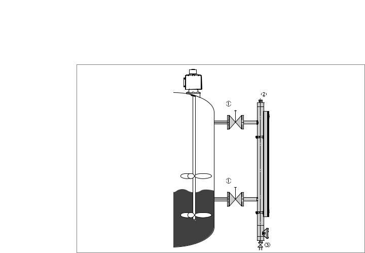
3.4.2 How to attach the bypass level indicator to the tank
Figure 3-5: How to attach the bypass level indicator to the tank
1Optional isolation valve
2Optional vent
3Optional drain with isolation valve
Obey the instructions that follow:
•Select bolts and gaskets (not supplied) that agree with the pressure rating of the process connection and the operating pressure.
•Install the bypass level indicator vertically on the tank.
•Make sure that there is no contamination (dirt etc.) or unwanted objects in the measuring chamber.
•Make sure that mechanical loadings do not cause damage to the process connections. If necessary, put supports on the device.
•Install shut-off valves so that the device can be cleaned separately from the tank. Drain the device only when it is isolated from the tank.
10/2012 - 4000347004 - HB BM26 Basic/Adv R04 en |
www.krohne.com |
19 |
3 INSTALLATION |
|
|
|
|
|
|
|
BM 26 BASIC/ADVANCED |
|
|
|
|
|
|
|
|
|
|
|
|
|
|
|
|
|
|
|
|
|
|
|
|
|
|
|
|
|
|
|
|
|
|
|
|
|
|
|
|
|
|
|
|
|
|
|
|
|
|
|
|
|
|
|
|
|
|
|
|
|
|
|
|
|
|
|
|
|
|
|
|
|
|
|
|
|
|
|
|
|
|
|
|
|
|
|
|
|
|
|
|
|
|
|
|
|
|
|
|
|
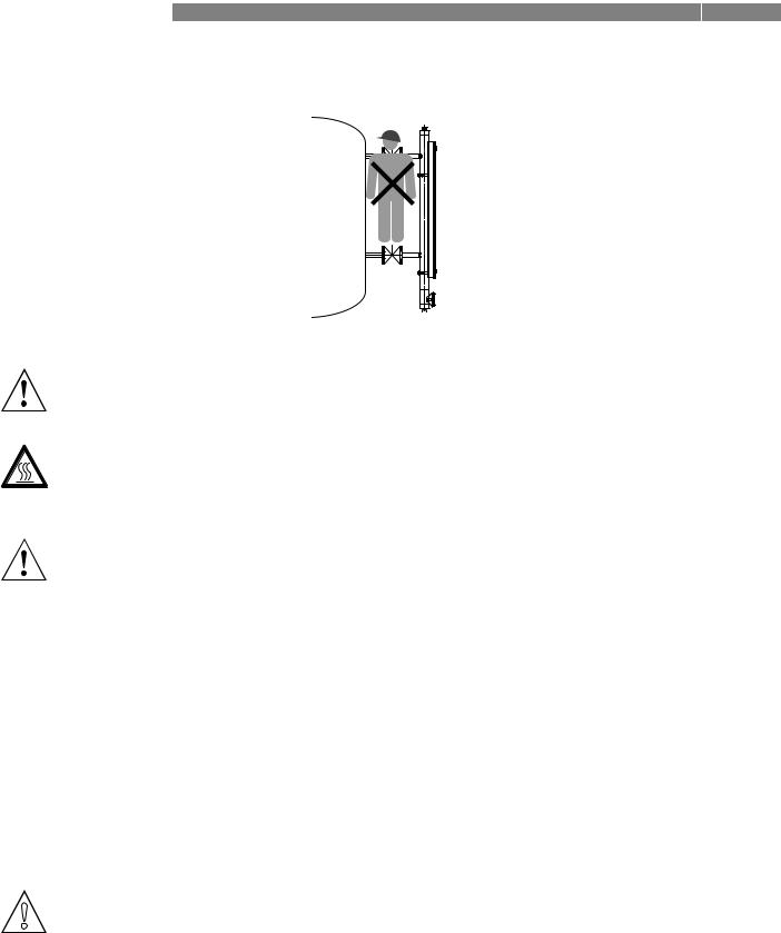
Figure 3-6: Stay away from the process connections
WARNING!
Stay away from the process connections. If you stand on the process connections, you can cause damage to the device and the installation.
DANGER!
Make sure that the outer surface temperature of the device is not more than 60°C / 140°F. If the surface temperature is more than 60°C / 140°F, use the device with precautions that agree with Health and Safety rules and regulations.
WARNING!
Pressure Equipment Directive 97/23/EC data
•The process connections must be attached correctly to prevent mechanical stress. The axis of the process connection must be parallel to and centred with the axis of the tank's process connections. Tighten the process connections in agreement with the design code.
•The user must take necessary steps to protect the installed device from shock waves (water hammer). A pressure limiting valve must protect the installation.
•The effective pressure of the installation (the maximum permitted by the pressure limiting valve) must never be greater than the maximum permitted pressure, Ps, marked on the device nameplate.
•Make sure that the parts in contact with the fluid are compatible with the fluid and conform to the ageing characteristics of the measurement environment and the fluid used. These have either been recommended in the instructions or form the subject of a particular specification in the contract.
•The external pressure, Pext, must be equal to atmospheric pressure, Patmos (Pext = Patmos).
•If stainless steel devices are more than 6 m / 20 ft high, we recommend more anchoring points.
CAUTION!
Before you fill the tank, make sure that the column of rotating flaps is set to zero (the flaps are all black). If not, the device may incorrectly indicate the level.
20 |
www.krohne.com |
10/2012 - 4000347004 - HB BM26 Basic/Adv R04 en |
|
|
|
INSTALLATION 3 |
|
BM 26 BASIC/ADVANCED |
||
|
|
|
|
|
|
|
|
|
|
|
|
Figure 3-7: Set the indicator column to zero
1 Magnet - point the red end of the magnet at the glass tube
Equipment needed:
• Magnet (supplied with the device)
How to make sure the column of rotating flaps is set to zero
•Hold the magnet in front of the glass tube at the bottom of the indicator column. i Make sure the red end of the magnet points at the glass tube.
•Move the magnet slowly up to the top the glass tube.
iThe flaps all turn to black. The indicator column is set to zero. You can now fill the tank.
3.5Level indicator column
The level indicator column is attached to the measuring chamber before delivery. Customer order data is used to calibrate its position. No other adjustment is necessary.
CAUTION!
Customer order data is used to calibrate the device. If liquid density changes, the device will not measure correctly. Please contact our nearest sales office for advice.
10/2012 - 4000347004 - HB BM26 Basic/Adv R04 en |
www.krohne.com |
21 |
3 INSTALLATION |
BM 26 BASIC/ADVANCED |
|
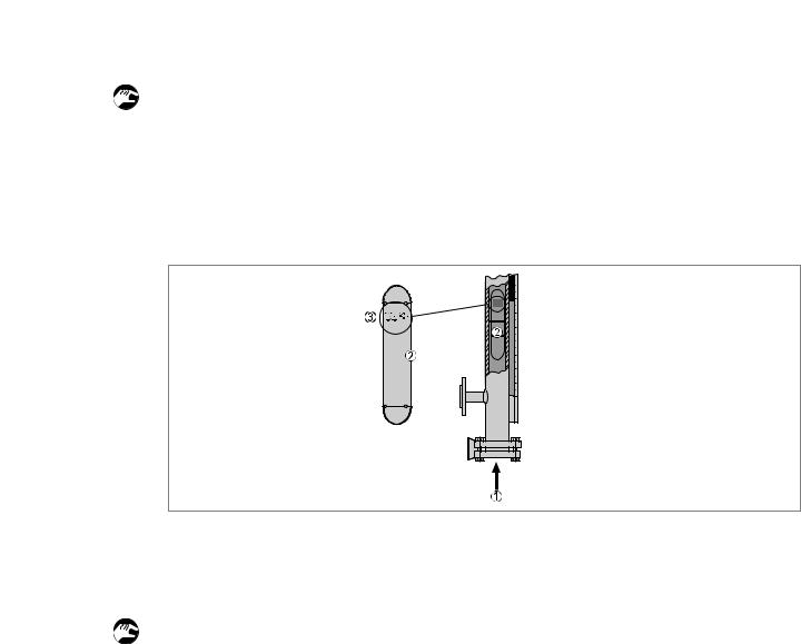
3.6 Optional analog transmitter
The analog transmitter is attached to the measuring chamber before delivery. Customer order data is used to calibrate its position. No other adjustment is necessary.
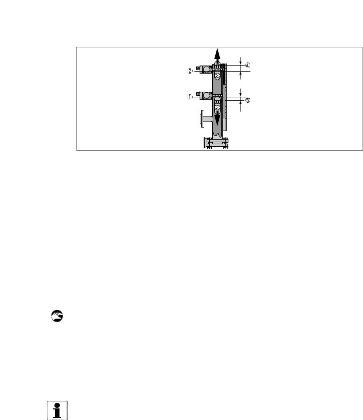
WARNING!
Too much heat can cause damage to the analog transmitter. If the process temperature is more than 120°C / 250°F, put insulation between the bypass chamber and the analog transmitter. If the process temperature is more than 150°C / 300°F, do not cover any part of the analog transmitter.
Figure 3-8: Analog transmitter and insulation for the bypass chamber
1Analog transmitter
2Bypass chamber (cross-section)
3If temperature is more 120°C / 250°F, put insulation between the bypass chamber and the analog transmitter
4Insulation (cross-section). If temperature is more 150°C / 300°F, do not cover any part of the analog transmitter with insulation.
CAUTION!
Do not move the analog transmitter. If you adjust the position of this device, the current output will be incorrect.
CAUTION!
Customer order data is used to calibrate the device. If liquid density changes, the device will not measure correctly. Please contact our nearest sales office for advice.
22 |
www.krohne.com |
10/2012 - 4000347004 - HB BM26 Basic/Adv R04 en |
|
|
INSTALLATION 3 |
|
BM 26 BASIC/ADVANCED |
|
|
|
|
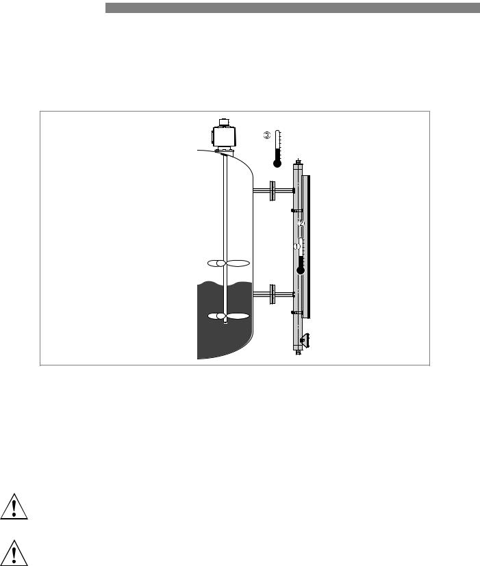
3.7 Optional limit switch
INFORMATION!
The level switches are not attached to the device before delivery. Remove the switches from the packing and obey the instructions that follow.
WARNING!
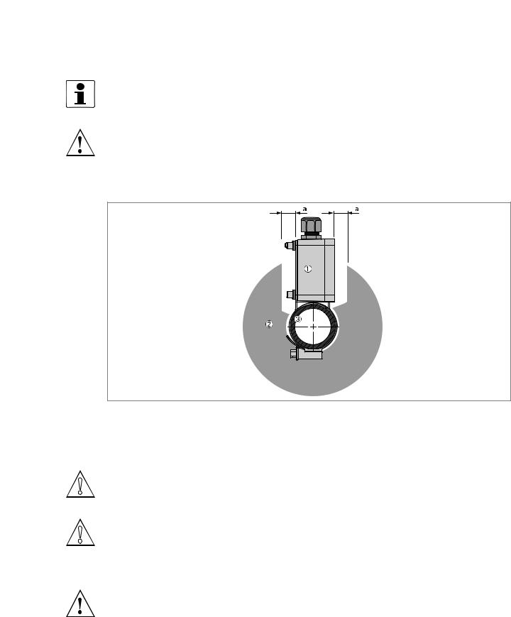
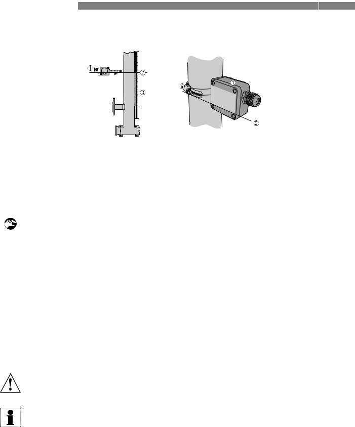
Too much heat can cause damage to the limit switch. If you put insulation around the bypass level indicator, do not cover the limit switch housing. Make sure that there is approximately 15 mm / 0.6¨ of empty space between the limit switch and the insulation.
Figure 3-9: Limit switches and insulation for the measuring chamber
1Limit switch housing
2Insulation around the measuring chamber (cross-section)
3Measuring chamber (cross-section)
Empty space between the limit switch and the insulation for the measuring chamber, a ≥15 mm / 0.6¨.
CAUTION!
If liquid density changes, the switch will not detect level correctly. Recalculate the position of the switch according to the true liquid density and repeat the installation procedure that follows.
CAUTION!
The switching point of the switch when the level increases is not in the same as the switching point of the switch when the level decreases. Does the limit switch have to be open when the float is above (for HIGH limit switches) or below (for LOW limit switches) the switching point? For more data, refer to Definition of switching point offset.
WARNING!
If you put insulation around the bypass level indicator, do not cover the limit switch housing. Too much heat can cause damage to the limit switch.
10/2012 - 4000347004 - HB BM26 Basic/Adv R04 en |
www.krohne.com |
23 |
3 INSTALLATION |
|
|
|
|
|
|
|
|
|
|
|
|
BM 26 BASIC/ADVANCED |
|
|
|
|
|
|
|
|
|
|
|
|
|
|
|
|
|
|
|
|
|
|
|
|
|
|
|
|
|
|
|
|
|
|
|
|
|
|
|
|
|
|
|
|
|
|
|
|
|
|
|
|
|
|
|
|
|
|
|
|
|
|
|
|
|
|
|
|
|
|
|
|
|
|
|
|
|
|
|
|
|
|
|
|
|
|
|
|
|
|
|
|
|
|
|
|
|
|
|
|
|
|
|
|
|
|
|
|
|
|
|
|
|
|
|
|
|
|
|
|
|
|
|
|
|
|
|
|
|
|
|
|
|
|
|
|
|
|
|
|
|
|
|
|
|
|
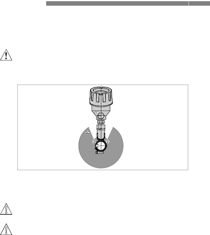
Figure 3-10: How to attach a limit switch
1Limit switch
2Switching point centreline
3Level indicator and optional measuring scale
4Limit switch clamp
Equipment needed:
• Large slotted tip screwdriver (not supplied)
Installation procedure
•Use the clamp to attach the limit switch to the measuring chamber. Do not tighten the clamp. i The cable gland must be at the bottom of the housing.
•Move the limit switch until the switching point centreline is at the level required. Refer to the level indicator scale to help you position the limit switch.
iIf the indicator column does not have the scale option, it will be necessary to calculate the vertical offset of the float magnet in relation to the level of the liquid (depends on the liquid density). Adjust the switch position for the float magnet offset. For the vertical offset tables, refer to the appendix in the Handbook.
• Adjust the switch position for the switching point offset.
i If the limit switch is set to LOW limit (the switch is open when the float is below the switching point), move the switch up a small distance to adjust for the offset. If the limit switch is set to HIGH limit (the switch is open when the float is above the switching point), move the switch down a small distance to adjust for the offset. For more data, refer to
Definition of switching point offset and Switching point offset values.
• Tighten the limit switch clamp.
WARNING!
Make sure the cable gland is on the bottom the housing and is tight to stop liquid entering the housing.
INFORMATION!
Liquid level offset
For a description of the liquid level offset, refer to Liquid level offset: description on page 79. For the graphs and other correction data, refer to Liquid level offset: correction data on page 80.
24 |
www.krohne.com |
10/2012 - 4000347004 - HB BM26 Basic/Adv R04 en |
|
|
INSTALLATION 3 |
|
BM 26 BASIC/ADVANCED |
|
|
|
|
Definition of switching point offset
a
a
Figure 3-11: Switching point offset
1Zero point of the limit switch
2Zero point of the limit switch
3Float and float magnet (switching point is in relation to the top of the magnet)
4True switching point above a limit switch (the switch is open when the liquid level goes above this point - a HIGH limit switch)
5True switching point below the limit switch (the switch is open when the liquid level goes below this point - a LOW limit switch)
Switching point offset values
Conditions |
Switching point offset, a |
|
|
|
|
|
mm |
inches |
|
|
|
When the switch must be open above the |
15 |
0.6 |
switching point (a HIGH limit switch), |
|
|
move the switch below the switching point: |
|
|
|
|
|
When the switch must be open below the |
0 |
0 |
switching point (a LOW limit switch), |
|
|
move the switch above the switching point: |
|
|
|
|
|
Installation of a limit switch for float failure detection
•Make sure the measuring chamber is empty and the float is in the chamber.
•Attach a limit switch to the bottom of the measuring chamber. Do not tighten the clamp.
•Connect the limit switch to the electrical circuit. Make sure that it is set to LOW limit. For more data, refer to Optional limit switches on page 29.
•Energize the electrical circuit.
•Lift the limit switch up the measuring chamber until the limit switch status changes to open.
•Hold the limit switch tightly in this position and tighten the clamp.
i The limit switch is in the correct position.
INFORMATION!
The float will go to the bottom of the measuring chamber for the reasons that follow:
•damaged or corroded float (float failure),
•liquid density that does not correspond to the specifications received with the order and
•draining the measuring chamber
For more data, refer to Errors on page 37.
10/2012 - 4000347004 - HB BM26 Basic/Adv R04 en |
www.krohne.com |
25 |

3 INSTALLATION |
BM 26 BASIC/ADVANCED |
|
3.8 Electromagnetic compatibility
The design of the device agrees with European Standard EN 61326-1 and Immunity and
Emissions requirements for industrial environments.
26 |
www.krohne.com |
10/2012 - 4000347004 - HB BM26 Basic/Adv R04 en |
 BM 26 BASIC/ADVANCED ELECTRICAL CONNECTIONS 4
4.1 Optional analog transmitter
• Remove the terminal compartment cover.
• Connect the device to the electrical circuit. Obey the national electrical codes.
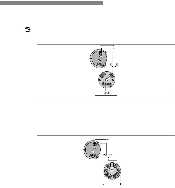
Figure 4-1: Electrical schematic for the 4...20 mA output module
1Power supply terminals
2Internal wiring - brown wire
3Internal wiring - red wire
4Optional LCD indicator
5Power supply (+) - if optional LCD connected - red wire
6Power supply (-) - if optional LCD connected - black wire
7LCD power supply terminal (10...35 VDC)
Figure 4-2: Electrical schematic for the 4...20 mA + HART output module
1Power supply terminals
2Internal wiring - brown wire
3Internal wiring - red wire
4Optional LCD indicator
5Power supply (+) - if optional LCD connected - red wire
6Power supply (-) - if optional LCD connected - black wire
7LCD power supply terminal (10...35 VDC)
10/2012 - 4000347004 - HB BM26 Basic/Adv R04 en |
www.krohne.com |
27 |
4 ELECTRICAL CONNECTIONS |
|
|
|
|
|
|
|
|
|
|
BM 26 BASIC/ADVANCED |
|
|||
|
|
|
|
|
|
|
|
|
|
|
|
|
|
|
|
|
|
|
|
|
|
|
|
|
|
|
|
|
|
|
|
|
|
|
|
|
|
|
|
|
|
|
|
|
|
|
|
|
|
|
|
|
|
|
|
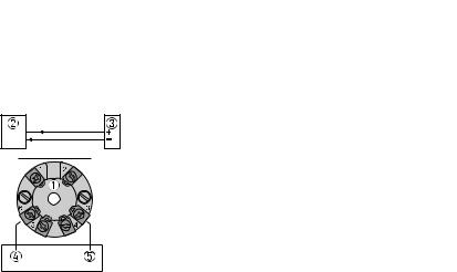
Figure 4-3: Electrical schematic for the FOUNDATION™ Fieldbus / PROFIBUS PA module
1Bus connection terminals
2Segment coupler
3Bus termination
4Internal wiring - orange wire
5Internal wiring - brown wire
For more electrical data, refer to Technical data: optional analog transmitter on page 51.
28 |
www.krohne.com |
10/2012 - 4000347004 - HB BM26 Basic/Adv R04 en |
|
|
ELECTRICAL CONNECTIONS 4 |
|
BM 26 BASIC/ADVANCED |
|
|
|
|
4.2 Optional limit switches


 1 2 3
1 2 3
Figure 4-4: Terminal compartment
1Terminal compartment cover
2Bistable reed switch
3Output terminal
•Remove the terminal compartment cover.
•Connect the device to the electrical circuit. Obey the national electrical codes.
WARNING!
If the switch is set to LOW limit, make sure that switch is open when the float is below the switch position.
If the switch is set to HIGH limit, make sure that switch is open when the float is above the switch position.
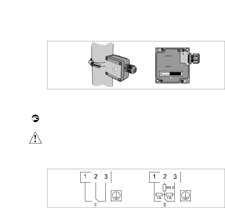
Figure 4-5: Electrical schema
1Non-NAMUR version
2NAMUR version
For more electrical data, refer to Technical data: optional limit switches on page 56.
10/2012 - 4000347004 - HB BM26 Basic/Adv R04 en |
www.krohne.com |
29 |
 Loading...