


KitchenAid KSBP25FKSS00, KSBS25FKBT00, KSCS25FKSS00, KSFS25FKBL00, KSFS25FKBT00 User Manual
...
KAR-12
TECHNICAL EDUCATION
MODELS:
KSBP25FKSS00
KSBS25FKBL00
KSBS25FKBT00
KSBS25FKWH00
KSCS25FKSS00
KSFS25FKBL00
KSFS25FKBT00
KSFS25FKWH00
2001 K MODEL
COUNTER DEPTH
SIDE-BY-SIDE REFRIGERATOR
WITH VARIABLE
CAPACITY COMPRESSOR
JOB AID 4317290A
FORWARD
This Job Aid, “KitchenAid 2001 K Model Counter Depth Side-By-Side Refrigerator With Variable Capacity Compressor” (Part No. 4317290A), provides the technician with information on the installation and service of the Side-By-Side Refrigerator. It is to be used as a training Job Aid and Service Manual. For specific information on the model being serviced, refer to the “Use and Care Guide,” or “Tech Sheet” provided with the refrigerator.
The Wiring Diagrams and Strip Circuits used in this Job Aid are typical and should be used for training purposes only. Always use the Wiring Diagram supplied with the product when servicing the unit.
GOALS AND OBJECTIVES
The goal of this Job Aid is to provide detailed information that will enable the service technician to properly diagnose malfunctions and repair the Side-By-Side Refrigerator.
The objectives of this Job Aid are to:
•Understand and follow proper safety precautions.
•Successfully troubleshoot and diagnose malfunctions.
•Successfully perform necessary repairs.
•Successfully return the Side-By-Side Refrigerator to its proper operational status.
WHIRLPOOL CORPORATION assumes no responsibility for any repairs made on our products by anyone other than Authorized Service Technicians.
Copyright © 2002, Whirlpool Corporation, Benton Harbor, MI 49022
- ii -
TABLE OF CONTENTS
|
Page |
GENERAL............................................................................................................................... |
1-1 |
Safety First......................................................................................................................... |
1-1 |
Electrical Power Supply & Grounding Requirements ................................................... |
1-1 |
Electrostatic Discharge (ESD) Sensitive Electronics.................................................... |
1-2 |
Model & Serial Number Designations ................................................................................ |
1-3 |
Model & Serial Number Label And Tech Sheet Locations................................................. |
1-4 |
Specifications..................................................................................................................... |
1-5 |
Refrigerator Warranty ........................................................................................................ |
1-7 |
INSTALLATION INFORMATION ........................................................................................... |
2-1 |
THEORY OF OPERATION ..................................................................................................... |
3-1 |
COMPONENT ACCESS ......................................................................................................... |
4-1 |
Component Locations ........................................................................................................ |
4-1 |
Removing The Touch/Display Board, The Insert And Overlay, |
|
& The Motorized Air Door ............................................................................................... |
4-2 |
Removing A Thermistor ..................................................................................................... |
4-4 |
Removing A Door Switch ................................................................................................... |
4-5 |
Removing A Light Socket .................................................................................................. |
4-6 |
Removing The Water Reservoir ........................................................................................ |
4-7 |
Removing The Ice Maker And The Auger Motor & Crush/Cube Solenoid......................... |
4-9 |
Removing The Evaporator Fan Motor, The Bimetal, |
|
The Defrost Heater, & The Evaporator ......................................................................... |
4-11 |
Removing The Condenser Fan Motor ............................................................................. |
4-15 |
Removing The Compressor ............................................................................................. |
4-16 |
Removing The Inverter Assembly.................................................................................... |
4-17 |
Removing The Main Control Board Assembly ................................................................. |
4-18 |
Removing The Water Dispenser Fill Tube ....................................................................... |
4-20 |
Removing The Water Valve ............................................................................................. |
4-22 |
Removing The Freezer Door Handles & Freezer Door ................................................... |
4-23 |
Removing A Roller ........................................................................................................... |
4-25 |
COMPONENT TESTING ........................................................................................................ |
5-1 |
Thermistor.......................................................................................................................... |
5-1 |
Evaporator Fan Motor ........................................................................................................ |
5-2 |
Condenser Fan Motor ........................................................................................................ |
5-2 |
Compressor & Inverter....................................................................................................... |
5-3 |
Motorized Air Door ............................................................................................................. |
5-4 |
Defrost Heater & Bimetal ................................................................................................... |
5-4 |
Main Control Board ............................................................................................................ |
5-5 |
Crush/Cube Solenoid......................................................................................................... |
5-6 |
Ice Maker Auger Motor ...................................................................................................... |
5-6 |
Water Valve Solenoid ........................................................................................................ |
5-7 |
Door Switch ....................................................................................................................... |
5-7 |
- iii -
|
Page |
DIAGNOSIS & TROUBLESHOOTING ................................................................................... |
6-1 |
Diagnosis ........................................................................................................................... |
6-1 |
Pre-Diagnostics Checks ................................................................................................. |
6-1 |
Diagnostics Mode ........................................................................................................... |
6-1 |
Water Filter Input (WFI) Test .......................................................................................... |
6-2 |
Troubleshooting Chart ....................................................................................................... |
6-3 |
WIRING DIAGRAMS & STRIP CIRCUITS ............................................................................. |
7-1 |
Wiring Diagram .................................................................................................................. |
7-1 |
Strip Circuits ...................................................................................................................... |
7-2 |
- iv -
GENERAL
SAFETY FIRST
Your safety and the safety of others is very important.
We have provided many important safety messages in this Job Aid and on the appliance. Always read and obey all safety messages.
This is the safety alert symbol.
This symbol alerts you to hazards that can kill or hurt you and others.
All safety messages will follow the safety alert symbol and either the word “DANGER” or “WARNING.” These words mean:
You can be killed or seriously injured if you don’t immediately follow instructions.
You can be killed or seriously injured if you don’t follow instructions.
All safety messages will tell you what the potential hazard is, tell you how to reduce the chance of injury, and tell you what can happen if the instructions are not followed.
ELECTRICAL POWER SUPPLY & GROUNDING REQUIREMENTS
Electrical Shock Hazard Disconnect power before servicing. Replace all panels before operating. Failure to do so can result in death or electrical shock.
Electrical Shock Hazard Plug into a grounded 3-prong outlet. Do not remove ground prong.
Do not use an adapter.
Do not use an extension cord.
Failure to follow these instructions can result in death, fire, or electrical shock.
1-1
Electrical Shock Hazard
Connect green ground wire to ground screw.
Failure to do so can result in death or electrical shock.
ELECTROSTATIC DISCHARGE (ESD) SENSITIVE ELECTRONICS
ESD problems are present everywhere. ESD may damage or weaken the electronic control assembly. The new control assembly may appear to work well after repair is finished, but failure may occur at a later date due to ESD stress.
•Use an antistatic wrist strap. Connect the wrist strap to a green ground connection point or unpainted metal in the appliance; or touchyourfingerrepeatedlytoagreenground connection point or unpainted metal in the appliance.
•Before removing the part from its package, touch the antistatic bag to a green ground connection point or unpainted metal in the appliance.
•Avoid touching electronic parts or terminal contacts. Handle the electronic control assembly by the edges only.
•When repackaging the failed electronic control assembly in an antistatic bag, observe the above instructions.
1-2
MODEL & SERIAL NUMBER DESIGNATIONS
MODEL NUMBER
MODEL NUMBER |
K SB S 25 F K WH 0 0 |
|
||||||||||||||||
|
|
|
|
|
|
|
|
|
|
|
|
|
|
|
|
|
|
|
PRODUCT GROUP
K = KitchenAid Brand
PRODUCT IDENTIFICATION
BR = Bottom Freezer Reversible Door
SB = Counter Depth Factory Installed Trim
SC = Counter Depth Architect Style
SF = Counter Depth Side By Side
SR = Side By Side Regular
TR = Top Freezer Reversible Door
MERCHANDISING SCHEME/SERIES
CAPACITY/CUBIC FOOT SIZE
MODEL FEATURES
YEAR OF INTRODUCTION
K = 2001
COLOR CODE
WH = White
ENERGY/POWER DESIGNATOR (NUMERIC)
0 = Original, 1 = 1st Change, 2 = 2nd Change, Etc.
ENGINEERING CHANGE (NUMERIC)
0 = Original, 1 = 1st Change, 2 = 2nd Change, Etc.
SERIAL NUMBER
SERIAL NUMBER |
S L 30 10001 |
|
||||||
|
|
|
|
|
|
|
|
|
MANUFACTURING SITE
S = Fort Smith, AR
YEAR OF PRODUCTION
L = 2001
WEEK OF PRODUCTION
30th WEEK
PRODUCT SEQUENCE NUMBER
1-3
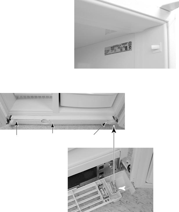
MODEL & SERIAL NUMBER LABEL
AND TECH SHEET LOCATIONS
The Model/Serial Number Label and Tech Sheet locations are shown below.
Model & Serial Number Location 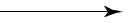
(Refrigerator Compartment)
Screw |
Base Grille |
Screw |
|
 Tech Sheet
Location
(Behind Base
Grille)
1-4

SPECIFICATIONS
Model Number |
KSBP25FKSS |
KSBS25FKBL |
KSBS25FKBT |
|
|
KitchenAid Counter Depth Factory |
KitchenAid Counter Depth Black |
KitchenAid Counter Depth Biscuit |
|
Model Description |
Installed SS Panel Black Dispenser |
Dispensing Trim Model |
Dispensing Trim Model |
|
Size-Configuration |
25' Counter Depth |
25' Counter Depth |
25' Counter Depth |
|
Cabinet Height (Floor To Top Of Cabinet) (in) |
71 1/2 |
71 1/2 |
71 1/2 |
|
Overall Height (Floor To Top Of Hinge Covers) (in) |
71 7/8 |
71 7/8 |
71 7/8 |
|
Cabinet Width (in) |
35 1/2 |
35 1/2 |
35 1/2 |
|
Overall Depth (Including Hardware & Handles) (in) |
29 |
3/8 |
29 3/8 |
29 3/8 |
Depth - Less Doors/Base Grille (Minimum Opening) (in) |
23 |
5/8 |
2 4 |
2 4 |
Crated Weight (lbs) |
360 |
360 |
360 |
|
Cabinet Color |
Black |
Black |
Biscuit |
|
Cabinet Hinge Cover Color |
Black |
Black |
Biscuit |
|
Cabinet Center Rail Color |
Black |
Black |
Biscuit |
|
Cabinet Deck Rail Color |
Black |
Black |
Biscuit |
|
Cabinet Base Grille/Color |
Black |
Black |
Biscuit |
|
Cabinet Rollers |
Front/Rear Adjust |
Front/Rear Adjust |
Front/Rear Adjust |
|
Refrigerant |
R134a |
R134a |
R134a |
|
Energy Star |
Energy Star |
Energy Star |
Energy Star |
|
Control Type |
Electronic ITC |
Electronic ITC |
Electronic ITC |
|
Standard Warranty (Months) |
12 |
12 |
12 |
|
Full Liner And Sealed System Warranty (Months) |
60 |
60 |
60 |
|
Model Number |
KSBS25FKWH |
KSCS25FKSS |
KSFS25FKBL |
|
|
KitchenAid Counter Depth White |
KitchenAid Counter Depth Architect |
KitchenAid Counter Depth Black |
|
Model Description |
Dispensing Trim Model |
Series Stainless Wrap Dispenser |
Freestanding Dispensing |
|
Size-Configuration |
25' Counter Depth |
25' Counter Depth |
25' Counter Depth |
|
Cabinet Height (Floor To Top Of Cabinet) (in) |
71 1/2 |
71 1/2 |
71 1/2 |
|
Overall Height (Floor To Top Of Hinge Covers) (in) |
71 7/8 |
71 3/4 |
71 |
3/4 |
Cabinet Width (in) |
35 1/2 |
35 1/2 |
35 1/2 |
|
Overall Depth (Including Hardware & Handles) (in) |
29 3/8 |
29 1/2 |
29 |
3/8 |
Depth - Less Doors/Base Grille (Minimum Opening) (in) |
2 4 |
2 4 |
23 |
5/8 |
Crated Weight (lbs) |
360 |
360 |
360 |
|
Cabinet Color |
White |
Black |
Black |
|
Cabinet Hinge Cover Color |
White |
Black |
Black |
|
Cabinet Center Rail Color |
White |
Black |
Black |
|
Cabinet Deck Rail Color |
White |
Black |
Black |
|
Cabinet Base Grille/Color |
White |
Black |
Black |
|
Cabinet Rollers |
Front/Rear Adjust |
Front/Rear Adjust |
Front/Rear Adjust |
|
Refrigerant |
R134a |
R134a |
R134a |
|
Energy Star |
Energy Star |
Energy Star |
Energy Star |
|
Control Type |
Electronic ITC |
|
Electronic ITC |
|
Standard Warranty (Months) |
12 |
12 |
12 |
|
Full Liner And Sealed System Warranty (Months) |
60 |
60 |
60 |
|
1-5

Model Number |
KSFS25FKBT |
KSFS25FKWH |
||
|
KitchenAid Counter Depth Biscuit |
KitchenAid Counter Depth White |
||
Model Description |
Freestanding Dispensing |
Freestanding Dispensing |
||
Size-Configuration |
25' Counter Depth |
25' Counter Depth |
||
Cabinet Height (Floor To Top Of Cabinet) (in) |
71 1/2 |
71 1/2 |
||
Overall Height (Floor To Top Of Hinge Covers) (in) |
71 |
3/4 |
71 |
3/4 |
Cabinet Width (in) |
35 1/2 |
35 1/2 |
||
Overall Depth (Including Hardware & Handles) (in) |
29 |
3/8 |
29 |
3/8 |
Depth - Less Doors/Base Grille (Minimum Opening) (in) |
23 |
5/8 |
23 |
5/8 |
Crated Weight (lbs) |
360 |
360 |
||
Cabinet Color |
Biscuit |
White |
||
Cabinet Hinge Cover Color |
Biscuit |
White |
||
Cabinet Center Rail Color |
Biscuit |
White |
||
Cabinet Deck Rail Color |
Biscuit |
White |
||
Cabinet Base Grille/Color |
Biscuit |
White |
||
Cabinet Rollers |
Front/Rear Adjust |
Front/Rear Adjust |
||
Refrigerant |
R134a |
R134a |
||
Energy Star |
Energy Star |
Energy Star |
||
Control Type |
Electronic ITC |
Electronic ITC |
||
Standard Warranty (Months) |
12 |
12 |
||
Full Liner And Sealed System Warranty (Months) |
60 |
60 |
||
1-6
REFRIGERATOR WARRANTY
ONE-YEAR FULL WARRANTY ON REFRIGERATOR
For one year from the date of purchase, when this refrigerator (excluding the water filter) is operated and maintained according to instructions attached to or furnished with the product, KitchenAid will pay for factory specified replacement parts and repair labor costs to correct defects in materials or workmanship. Service must be provided by a KitchenAid designated service company. On models with a water filter: 30 day limited warranty on water filter. For 30 days from the date of purchase, when this filter is operated and maintained according to instructions attached to or furnished with the product, KitchenAid will pay for replacement parts to correct defects in materials and workmanship.
SECOND THROUGH FIFTH YEAR LIMITED WARRANTY
In second through fifth years from the date of purchase, KitchenAid will pay for replacement or repair of the refrigerator/freezer cavity liner (including labor costs) if the part cracks due to defective materials or workmanship.
Service must be provided by a KitchenAid designated service company. Also, KitchenAid will pay for factory specified replacement parts and repair labor costs to correct defects in materials or workmanship in the sealed refrigeration system. These parts are: compressor, evaporator, condenser, dryer, and connecting tubing. Service must be performed by a KitchenAid designated service company.
SIXTH THROUGH TENTH YEAR LIMITED WARRANTY
In sixth through tenth years from date of purchase, KitchenAid will pay for factory specified replacement parts to correct defects in materials or workmanship in the sealed refrigeration system. These parts are: compressor, evaporator, condenser, dryer, and connecting tubing.
LIMITED LIFETIME WARRANTY
In second year through life of product from date of purchase, KitchenAid will pay for replacement of all SLIDE N
LOCKTM Door Bins and SLIDE N LOCKTM Can Racks due to defective materials or workmanship.
KitchenAid will not pay for:
1.Service calls to correct the installation of the refrigerator, to instruct you how to use the refrigerator, to replace house fuses or correct house wiring or plumbing, to replace light bulbs, or replacement water filters other than as noted above.
2.Repairs when the refrigerator is used in other than normal, single-family household use.
3.Pickup and delivery. The refrigerator is designed to be repaired in the home.
4.Damage resulting from accident, alteration, misuse, abuse, fire, flood, improper installation, acts of God, or use of products not approved by KitchenAid or KitchenAid Canada.
5.Any food loss due to product failure.
6.Repairs to parts or systems resulting from unauthorized modifications made to the appliance.
7.Replacement parts or repair labor costs for units operated outside the United States or Canada.
8.In Canada, travel or transportation expenses for customers who reside in remote areas.
9.Any labor costs during the limited warranty period.
KITCHENAID AND KITCHENAID CANADA SHALL NOT BE LIABLE FOR INCIDENTAL OR CONSEQUENTIAL DAMAGES.
Some states or provinces do not allow the exclusion or limitation of incidental or consequential damages, so this exclusion or limitation may not apply to you. This warranty gives you specific legal rights, and you may also have other rights which vary from state to state or province to province.
Outside the 50 United States and Canada, this warranty does not apply. Contact the authorized KitchenAid dealer to determine if another warranty applies.
If you need service, first see the “Troubleshooting” section of the Use and Care Guide. After checking “Troubleshooting,” additional help can be found by checking the “Assistance or Service” section, or by calling the
KitchenAid Customer Interaction Center, 1-800-422-1230 (toll-free), from anywhere in the U.S.A. In Canada, contact the designated KitchenAid Canada Appliance service company, or call 1-800-807-6777.
1-7
— NOTES —
1-8
INSTALLATION INFORMATION
LEVELING THE REFRIGERATOR
IMPORTANT: All four leveling legs must contact the floor to support and stabilize the full weight of the refrigerator.
Base Grille Removal
1.Open the refrigerator doors.
NOTE: Do not remove the Tech Sheets fastened behind the grille.
2.Remove the screws from the base grille and remove the grille.
Adjusting The Rollers
The roller adjusting bolts are located behind the base grille. The refrigerator has four adjustable rollers: two in front, and two in the rear.
There are two sets of roller adjusting bolts found at the base of the refrigerator on each side. The rear leveling bolt (1) is yellow, and the front leveling bolt (2) is silver.
1
2
NOTE: Be careful not to unscrew the leveling bolts too much when lowering the refrigerator. The bolt head will start to come away from the refrigerator when it is in the lowest position. If the bolt comes out of the rear roller bracket, the compartment access cover on the back of the refrigerator will have to be removed to reinstall the bolt.
1.Use a 1/2″ (12.70 mm) socket wrench to adjust the leveling bolts. Turn the leveling bolt to the right to raise that side of the refrigerator, or turn the leveling bolt to the left to lower that side. It may take several turns of the leveling bolts to adjust the tilt of the refrigerator.
2.Adjust the front leveling bolt so that the top of the refrigerator is parallel with the cabinet above the refrigerator.
Forstandardcabinets,leaveapproximately 1/8″ (3.18 mm) gap between the top hinges and the cabinet.
For full-overlay cabinets, leave a 1/4″ (6.35 mm) gap for leveling.
If you do not have a cabinet above the refrigerator, adjust the refrigerator to make it level.
Cabinet 

Front Of 
Refrigerator
3.Adjust the rear leveling bolt and level the refrigerator with the side cabinets, or with the cabinet end panels.
4.If needed, use the four leveling bolts to raise the refrigerator to close the gap between the refrigerator top hinge, and the cabinet opening. Check to make sure that all four rollers still touch the floor, and that the cabinet doors above the refrigerator open all the way.
2-1
— NOTES —
2-2
THEORY OF OPERATION
Warmer Warmer
|
8 |
46 |
|
3.4 |
40.4 |
Water |
1.7 |
38.7 |
Filter |
0 |
37 |
|
||
|
–1.7 |
35.3 |
|
–3.4 |
33.6 |
|
–5.1 |
31.9 |
Cooler |
Cooler |
Power |
|
On/Off |
|
Freezer |
Refrigerator |
THE ELECTRONIC CONTROL PANEL
OVERVIEW
The KitchenAid Counter Depth Refrigerator Constant Flow Temperature Management System uses two thermistors to monitor temperature changes inside the refrigerator and freezer compartments. The electronic control manages the operation of the variable capacity compressor (VCC), a variable speed evaporator fan motor, and a variable position air door. The air door allows independent temperature control of the refrigerator and freezer compartments.
The electronic control seeks the most efficient means possible to maintain temperatures as it controls the operation and speed of the compressor and the evaporator fan motor. Higher fan speed is used before increasing the compressor speed to minimize power consumption. A nearly constant run time is sought at the lowest possible fan and compressor speed.
NOTE: The illustration above shows the actual temperature that is associated with each corresponding LED.
Freezer temperatures can be set from 8°F to –5°F (–13°C to –21°C). Refrigerator temperatures can be set from 46°F to 32°F, (8°C to 0°C).
The Adaptive Defrost Control (ADC) portion of the electronic control utilizes “pulsed defrost” technology to perform the defrost function (see page 3-4).
The electronic control monitors the water valve for total elapsed time and gallons of water used. The Water Filter Indicator (WFI) LED changes color to indicate that the filter needs to be replaced.
Pressing the Temperature Up or Down adjustment keys will change the refrigerator and freezer settings. One of seven (7) LEDs light to display the refrigerator and the freezer settings.
3-1
TEMPERATURE CONTROL
The electronic control checks the resistance of the thermistors, and compares it to both the customer temperature settings and the last thermistor reading taken. This information is used to determine when to begin a cooling operation, and if a change is necessary in the damper setting, or the evaporator fan or compressor speed.
When a warm refrigerator is first put into a cooling mode, the air door partially opens, and the compressor and evaporator fan motors start to run at maximum rpm. The air door will gradually move to its fully open position.
As the actual temperature in the refrigerator nears the selected temperature setting, the electronic control compares the temperatures in both compartments. The compartment that has the greatest need for cooling, will control the speed of the evaporator fan motor.
Freezer Temperature Control —
Temperature Increasing
When the freezer calls for cooling, the compressor begins to run at minimum rpm, (see the chart on page 3-3), and the evaporator fan begins to run at 2000 rpm. The compressor and evaporator speeds are continuously updated. Speed changes are made based on:
•The difference between the actual temperature and the selected temperature settings.
•The rate of temperature change.
If the temperature increases 4°F above the selected temperature setting, the evaporator fan speed begins to gradually increase. The evaporator fan motor reaches the maximum speed of 3000 rpm at 5°F above the selected temperature setting, and the compressor speed begins to gradually increase. A maximum compressor speed of 4500 rpm will be reached at 9°F above the selected temperature setting.
Freezer Temperature Control —
Temperature Decreasing
When the freezer temperature begins to decrease, the process will reverse. The compressor speed decreases, followed by the evaporator fan speed.
Refrigerator Temperature Control —
Temperature Increasing
When the refrigerator calls for cooling while the freezer is satisfied, the air door begins to open, and the evaporator fan starts to run at minimum speed. If the temperature continues to rise, the air door will continue to open. If the temperature continues to rise after the air door is fully open, the evaporator fan speed will gradually increase to a maximum of 3000 rpm. If the temperature continues to rise, the compressor starts to run, or if it has already been running, begins to increase in speed.
Refrigerator Temperature Control —
Temperature Decreasing
As the refrigerator temperature approaches the selected setting, the control compares the temperatures in both compartments to determine which compartment will control the fan speed. If the freezer is further from the selected temperature setting, it controls the fan speed, and the air door begins to close, thus reducing the airflow to the refrigerator.
If the freezer is satisfied, the air door remains open, and the fan speed begins to decrease. When the selected temperature setting is reached, the air door closes.
3-2

COMPRESSOR
The main control board supplies a 5 vdc, peak- to-peak square wave, at 54 to 150 Hz, to the inverter board. A standard VOM will read approximately 2.5 vdc. The inverter board supplies the variable capacity compressor with three-phase 230 vac. Varying the frequency to the inverter board, and not the voltage, changes the speed of the compressor. The compressor can run at speeds of 1620 to 4500 rpm.
NOTE: It is not necessary, nor is it recommended, to test the output of the inverter board.
While the compressor is running, its speed is continuously updated. Speed is determined after analyzing two factors:
•The difference between the actual temperature and the selected temperature settings.
•The rate of temperature change.
Minimum compressor speed is based on the freezer’s selected temperature setting, as shown in the following chart.
Freezer Temperature |
|
Compressor |
|
Setting |
|
Minimum Speed |
|
|
|
|
|
|
|
|
|
#1 - #5 |
|
1620 rpm |
|
# 6 |
|
1800 rpm |
|
# 7 |
|
2200 rpm |
|
The compressor generally cycles on and off according to the cut-in and cut-out temperatures of the freezer, however, the refrigerator can turn on the compressor if the evaporator fan is at maximum speed and the refrigerator temperatures are not dropping.
COMPRESSOR PROTECTION
To protect the compressor and maintain efficiency, minimum compressor off time is programmed into the control. When the compressor turns off, a minimum of 7 minutes must elapse before allowing a restart.
The inverter board utilizes a current limiting device and thermal protection that eliminates the need for a compressor mounted thermal protector.
EVAPORATOR FAN MOTOR
The evaporator fan motor is a 12 vdc, variable speed motor. The motor has four wires:
•A blue wire provides feedback to monitor the speed of the motor.
•A red wire provides a constant 12 vdc.
•A yellow wire provides a variable voltage of between 5 vdc and 17 vdc to control the motor speed from 2000 to 3000 rpm.
•A white wire provides a common return.
EVAPORATOR FAN &
AIR DOOR DELAY
After defrost, an evaporator fan delay prevents unnecessary movement of warm, moist air through the refrigerator, by chilling the evaporator prior to starting the fan. Immediately after defrost drip time, the compressor starts at 4500 rpm, but the evaporator fan is delayed for 8 minutes. The air door remains closed for 8 minutes following defrost.
AIR DOOR
The air door is driven by a reversible DC stepper motor. The motor operates on a 12 vdc, peak-to-peak square wave. Voltage is delivered to the air door in a series of short pulses. It is not possible to obtain a reliable voltage reading with a VOM.
Separate windings are used to move the air door open or closed. The door can be in any one of 1800 positions from 0 to 90 degrees. The air door is used to fine-tune the airflow to the refrigerator.
3-3
The refrigerator temperature determines the opening of the air door. When the refrigerator requires cooling, if the evaporator fan motor is already running for the freezer, the air door partially opens, and then adjusts, if necessary. While the refrigerator is cooling, the door will be adjusting continuously to maintain or recover refrigerator temperature.
ADAPTIVE DEFROST
The adaptive defrost control allows the unit to enter a defrost mode only when it is needed. When powered up for the first time, the control initiates a defrost cycle after 8 hours of compressor run time. By monitoring the duration of defrost heating time and compressor run time, the control will continuously adapt the time between defrosts to optimize efficiency. Time between defrost periods will vary between 8 and 100+ hours.
Defrost will occur immediately when the compressor has run at 4000 rpm or greater for 1 hour, and 8 hours have elapsed since the last defrost.
PULSED DEFROST
For the first 7 minutes of defrost, the heater is on continuously. It will then cycle off for 1 minute, and back on for 2 minutes. The heater will continue to cycle at this ratio until the bimetal opens, or until 33 minutes has elapsed. At this point, heat is discontinued, and a 4-minute “drip time” begins. This allows the water to drain before the unit returns to a cooling mode. Maximum defrost time, (pulsed heat on/off time + drip time) is 37 minutes.
When entering a defrost cycle, if the bimetal is open, the time to defrost is reset to 8 hours, and the control will time through the entire 37 minute defrost period. During diagnostics this will allow a technician time to look for heater operation, and if necessary, bypass the bimetal.
POWER INTERRUPTION
After a power interruption, the following events will occur:
•The unit returns to the same operating mode and settings in use prior to the power interruption. If the unit was off, it remains off.
•Initially, the compressor, evaporator fan, and condenser fan motors will be off.
•The air door will close, and then adjust to the proper opening. The evaporator fan starts when the air door opens.
•The adaptive defrost control resets the com-
pressor run time counter to 0, and if the freezer is above 20°F, the time to defrost is set to 8 hours.
•If the freezer temperature is below 12°F, the
compressor starts after a delay of 7 minutes. If the freezer temperature is above 12°F, the compressor starts immediately.
FAILURE DEFAULTS
In the event of a thermistor, or keypad failure, the control uses one of the following default modes, which will continue until the failure is corrected.
Refrigerator Thermistor
If the control senses an open or a shorted thermistor, the air door and the evaporator fan motor will begin to operate on a timed on and off cycle, based on current selected temperature settings. The evaporator fan motor will run when the air door is open.
At mid-settings of 37°F / 0°F, the air door will open for 16 minutes, and close for 30 minutes. Setting the freezer colder, or the refrigerator warmer, will reduce the door-open time. Setting the freezer warmer, or the refrigerator colder, will increase the door-open time.
3-4
Freezer Thermistor
If the control senses an open or a shorted thermistor, the compressor and the evaporator fan motor will begin to operate on a timed on and off cycle. The cycle time is based on current selected temperature settings.
At mid-settings of 37°F / 0°F, the compressor and the evaporator fan motors will run for 35 minutes, and be off for 25 minutes. Setting the freezer colder will increase the run time. Setting the freezer warmer will decrease the run time.
The compressor will run at minimum speed. The evaporator fan will also run at minimum speed, unless the refrigerator compartment requests a higher speed.
Keypad
If the control detects that the keypad is not working, it reverts to the default temperature settings of 37°F in the refrigerator, and 0°F in the freezer.
Evaporator Fan Motor
If the evaporator fan motor malfunctions, the compressor will run at 4500 rpm for an indefinite period, except during the defrost periods.
ELECTRONIC CONTROL
THERMAL SHUTOFF
The electronic control utilizes an on-board thermistor to shut the compressor off if the temperature rises above 160°F (71°C). When the temperature drops to 130°F (55°C), the compressor returns to normal operation. This cycle continues indefinitely until the cause of the high temperature has been corrected.
AIR CIRCULATION
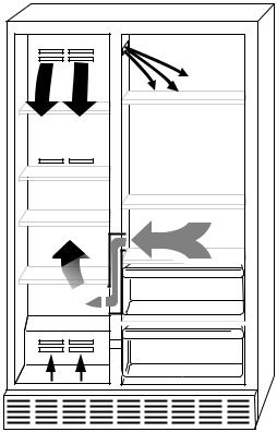
In order to ensure the proper refrigerator and freezer compartment temperatures, air must be able to flow between the two sections.
Air enters the bottom of the freezer compartment and moves up through the evaporator. Some of the cooled air from the evaporator is directed back into the freezer, and the rest goes into the refrigerator through the motorized air door. The refrigerator air then returns to the freezer through the bottom air return (see the illustration below).
It is important not to block any of the vents with food items. If the vents are blocked, airflow will be restricted, and the temperature management system will not function properly.
IMPORTANT: Because air circulates between both sections, any odors formed in one section will transfer to the other. Keep both sections clean, and wrap or cover foods tightly to prevent odors from occurring.
3-5
 Loading...