

Page 1
Inline Static Sensor
Important
Point
Reference
96M13428
SK-1000 Series
Instruction Manual
Read this instruction manual before using the product in order to achieve
maximum performance.
Keep this manual in a safe place after reading it for future reference.
Introduction
This manual describes the operations of and information related to the SK-1000
Series.
Read this manual carefully to ensure the safe performance and function of the
SK-1000 Series.
Keep this manual in a safe place for future reference.
Ensure that the end user of this product receives this manual.
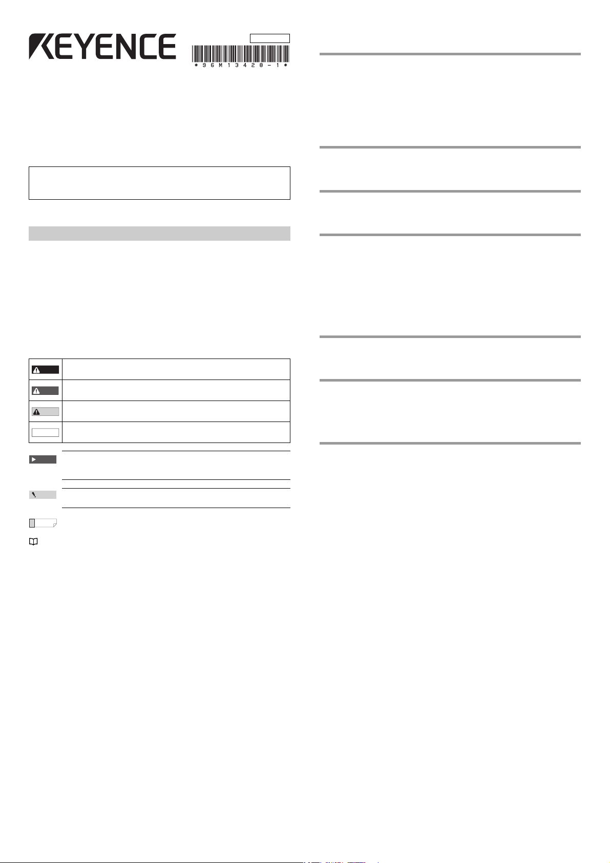
Symbols
The following symbols are used in this instruction manual to enable you to
recognize important information at a glance.
Be sure to read this section carefully.
Indicates a hazardous situation which, if not avoided, will result in
DANGER
death or serious injury.
Indicates a hazardous situation which, if not avoided, could result
WARNING
in death or serious injury.
Indicates a hazardous situation which, if not avoided, could result
CAUTION
in minor or moderate injury.
Indicates a situation which, if not avoided, could result in product
NOTICE
damage as well as property damage.
Table of Contents
Introduction ...................................................................................... 1
Safety Precautions ........................................................................................ 2
General Precautions .........................................................................2
Safety Information for the SK-1000 series ........................................ 2
Abnormal Conditions ........................................................................ 2
Precautions for Use ..........................................................................2
Other Precautions .............................................................................2
Precautions for Regulations and Standards ..................................................2
1. Before Use ................................................................................................ 3
Checking the Package Contents ...................................................... 3
Part Names and Functions ...............................................................3
2. Installation and Connection .......................................................................4
Mounting and Wiring the Sensor Amplifier ....................................... 4
Connecting and Mounting the Sensor Head ....................................5
3. Basic Operations ....................................................................................... 7
Operation When the Power is Turned on for the First Time ..............7
Operations on the Main Screens ...................................................... 7
Initial Reset (Initialize) ....................................................................... 8
Setting the Tolerance Values ............................................................ 9
Zero Shift Function
(Shifting the Internal Measurement Value (R.V.)) ............................. 9
Bank Function (Registering Multiple Tolerance Setting Values) ...... 9
Key Lock Function 10
4. Setting Various Functions ....................................................................... 10
Basic Settings and Advanced Settings .......................................... 10
Simulation Mode ............................................................................. 17
5. Specifications .......................................................................................... 17
Specifications ................................................................................. 17
Circuit Diagram .............................................................................. 18
Dimensions ..................................................................................... 18
Response Time ............................................................................... 19
Indicates cautions and limitations that must be followed during
operation.
Indicates additional information on proper operation.
Indicates tips for better understanding or useful information.
Indicates the reference pages in this manual or the reference pages in
separate manuals.
6. Appendix .................................................................................................19
Troubleshooting .............................................................................. 19
Display Screen and Output ............................................................ 21
Factory Setting (Default Value) List ................................................ 21
1
E SK-1000 IM
Page 2

Safety Precautions
NOTICE
NOTICE
General Precautions
• At startup and during operation, be sure to monitor the functions and
performance of this product and confirm normal operation.
• We recommend that you take substantial safety measures to avoid any damage
in the event that a problem occurs.
• If the product is modified or used in any way other than those described in the
specifications, its functions and performance cannot be guaranteed.
• When this product is used in combination with other devices, the functions and
performance may be weakened, depending on the operating conditions,
surrounding environment, etc.
• Do not use this product for the purpose of protecting the human body.
• Do not subject this device, including peripheral devices, to rapid temperature
change. Product failure may occur due to condensation.
Safety Information for the SK-1000 series
• This product is only intended to detect the charge on object(s).
Do not use this product for the purpose to protect a human body
or a part of human body.
WARNING
• This product is not intended for use as explosion-proof product.
Do not use this product in hazardous location and/or potentially
explosive atmosphere.
Warming up
Leave the SK Series about 30 minutes after turning on the power.
The circuit is not stable immediately after the power turns on, so the display value
may gradually fluctuate.
Abnormal Conditions
If the following conditions occur, turn OFF the power immediately.
Continuing to use this product under abnormal conditions may
cause product failure.
NOTICE
• When water or foreign matter enters the SK Series
• When the SK Series is dropped or the case is damaged
• If smoke or unpleasant odor is present.
Precautions for Use
• Use with the correct power source and voltage. Otherwise, fire,
electric shock or product failure may result.
CAUTION
• Do not attempt to open or modify the SK Series. Doing so may
cause fire or electric shock.
• Before disconnecting the cables, make sure to turn off the main
unit and devices connected to the main unit. Otherwise, the unit
may be damaged.
• Do not turn off the power while modifying settings. Some or all
of the setting data may be lost.
• The measurement area is basically a guide for measurement. A
proper size of target with respect to the measurement area is
recommended to ensure a more accurate measurement.
Power ON Reset
After the power is turned ON, it will take approx. 3.5 seconds for the measurement
to start. The judgment results will be output after the sampling rate has elapsed.
Other Precautions
Power source
• Noise superimposed on the power supply may cause malfunction. Use a direct
current stabilized power source which uses an insulation transformer.
• When using a commercially available switching regulator, make sure to ground
the frame ground terminal.
Grounding precautions
A grounding wire is present in the I/O cable of the SK-1000 Series.
• For proper measurements, be sure to connect the blue wire
protruding from the SK-1000 Series to ground.
• Use class-D grounding-resistance not exceeding 100 Ω.
Precautions for Regulations and Standards
CE Marking
Keyence corporation has confirmed that this product complies with the essential
requirements of the applicable EC Directives, based on the following
specifications.
Be sure to consider the following specifications when using this product in the
Member States of European Union.
z EMC Directive
• Applicable standards EN61326-1, ClassA
• This product is intended to be used in an industrial electromagnetic
environment.
Remarks
These specifications do not give any guarantee that the end-product with this
product incorporated complies with the essential requirements of EMC Directive.
The manufacturer of the end-product is solely responsible for the compliance on
the end-product itself according to EMC Directive.
FCC regulations
This product complies with the following EMI regulations specified by the FCC.
• Applicable standards FCC part 15 subpart B, class A digital device
IC (Industry Canada) regulations
This product complies with the following EMI regulations specified by IC.
• Applicable standards ICES-003, class A digital apparatus
Installation environment
To use this product normally and safely, do not install this product in the following
locations. Product failure may occur.
• High-humidity, dusty or poorly-ventilated locations
• High-temperature locations where the unit is exposed to direct sunlight
• Locations where there is corrosive or combustible gas
• Locations where the unit may be directly subjected to vibration or impact
• Locations where water, oil or chemicals may splash onto the unit
• Locations that cause the unit to discharge its static electricity
Influence of dirt
Measurement errors may occur due to dust, water, oil, etc.
Anti-noise prevention
When the unit is installed near electric noise source such as a power source or
high-voltage line, operational errors or product failure may occur. Take adequate
measures such as using a noise filter, separating cables or insulating the sensor
amplifier and the sensor head.
E SK-1000 IM
2
Page 3

1. Before Use
Sensor amplifier x 1
Instruction manual x 1
SK-1000 (main unit)
Sensor amplifier x 1
SK-1050 (expansion unit)
Sensor head x 1
SK-050
OP-26751 (for SK-1000/1050)
End unit x 2
OP-87056 (2 m)
OP-87057 (5 m)
OP-87058 (10 m)
OP87059 (20 m)
Sensor head connection cable
(M8 straight connector) x 1
OP-87660 (2 m)
OP-87661 (5 m)
OP-87662 (10 m)
OP87663 (20 m)
Sensor head connection cable
(M8 L-shaped connector) x 1
OP-84338
Sensor head
cable connector x 2
OP-87934
Ion balance monitor unit
Expansion unit connecto
r*1
Sensor head connector
Amplifier control unit cover
Expansion unit connector
*2
Amplifier control unit
(1)
(2)
(3)
(4)
(5) (6) (7) (8)
(9) (10) (11)
(12)
(13)(14)(15)
Part Names and Functions
This chapter gives an overview of the SK Series as well as the name and function
of each part.
Checking the Package Contents
The following equipment and accessories are included in the package. Before
using the unit, make sure that all items are included.
Sensor Amplifier
DIN rail mount type
Sensor Head
Sensor Amplifier Unit
SK-1000
HOLD
HI
GO
LO
ZERO SHIFT
0
BANK
1
2
3
TEMP %RH
HI LO R.V.
V
ZERO SHIFT
TIMING
SELECT
SET MODE
SK-1000
ALARM
kV
*1 When shipped from the factory, a protective cover is installed over the
expansion slots.
*2 Not installed on the main unit.
Amplifier control unit
kV
ALARM
HOLD
HI
GO
LO
ZERO SHIFT
0
BANK
1
2
3
TEMP %RH
HI LO R.V.
V
ZERO SHIFT
TIMING
SET MODE
SELECT
SK-1000
List of Optional Parts
Forsensoramplifier
Forsensorhead
Item Description
(1) Main display Displays the judgment value (P.V.) and each setting item.
(2) HOLD indicator
(3) Judgment indicator
(4) Bank indicator
Lights up when the judgment value (P.V.) is held.
"6. Hold Function" (page 12)
Displays whether the judgment val ue (P.V.) is HI (over the upper
limit), GO (within the acceptable range) or LO (below the lower
limit) against the tolerance setting value.
"Changing the Tolerance Values" (page 9)
Displays a bank in use.
"Bank Function (Registering Multiple Tolerance Setting Values)"
(page 9)
(5) Zero shift button
(6) Sub display indicator
(7) Sub display
(8) Timing input indicator
(9) Zero shift indicator
Press this button to match the internal measurement value (R.V.)
to zero.
Lights up according to the type of values displayed on the sub
display.
Displays the internal measurement value (R.V.), temperature,
humidity, and each setting (selection) item.
Lights up while the timing input is ON when the timing input
(external input) is set to Level. Lights on approx. 0.5 sec. when
the timing input is set to Edge and the timing input is turned ON.
The zero shift indicator will light up for approx. 0.5 second when
the zero shift function is used.
(10) SET button Used to perform initializations.
(11) MODE button
(12) Arrow button
Used when setting items, entering/exiting setting modes or
moving items.
Used when selecting settings, changing display contents on the
sub display, etc.
(13) Alarm indicator Lights up in the alarm state or error state.
kV display unit
(14)
(15)
indicator
V display unit
indicator
Lights up when the judgment value (P.V.) display unit is kV.
Lights up when the judgment value (P.V.) display unit is V.
3
E SK-1000 IM
Page 4
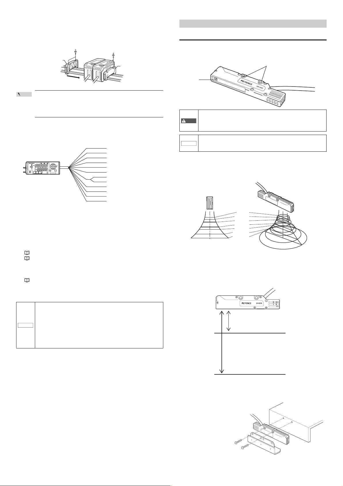
Sensor Head Unit
(3) Temperature/humidity sensor
(2) Surface potential sensor
(1) Sensor indicator light
NOTICE
①
②
③
Main unit
Connector cover
Main unit
Expansion unit
Connector
2. Installation and Connection
SK-050
Item Description
Lights up according to the judgment during normal operation.
(1) Sensor indicator light
Surface potential
(2)
sensor
Temperature/humidity
(3)
sensor
HI/LO: Lit in red
GO: Lit in green
OFF: Off
When an error occurs: Lit in red
This sensor detects the charge potential.
This sensor detects the temperature/humidity.
This chapter describes precautions when installing and connecting the SK Series.
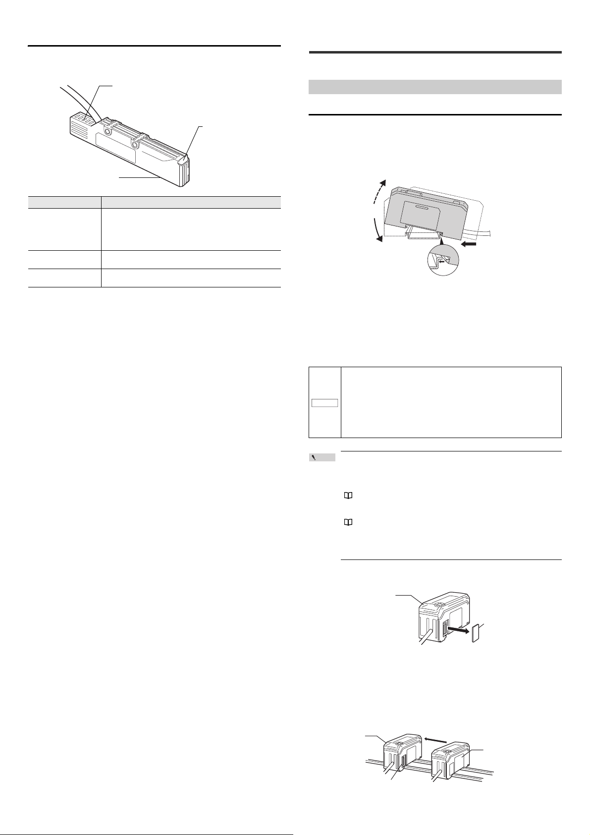
Mounting and Wiring the Sensor Amplifier
Mounting the Sensor Amplifier
SK-1000
1 Align the tab at the bottom of the amplifier body with the DIN rail.
While pushing the amplifier in the direction of the arrow (1), push
down in the direction of the arrow (2).
2 To dismount the sensor, raise the main body in the direction of the
arrow (3) while pushing the main body in the direction of the arrow
(1).
Expansion unit (SK-1050)
Incorporate multiple units into one system by connecting expansion units to the
main unit.
Up to 7 expansion units can be connected to one main unit.
• Always mount expansion units onto a DIN rail.
• When connecting multiple amplifiers (expansion units), first
check to make sure that the power is turned OFF to all of the
main and expansion units. Connecting the units with the power
turned ON may cause damage to the units.
• Position the amplifiers (expansion units) as close as possible to
the main unit. Improper connections may damage the
equipment.
Point
• When connecting the expansion units, make sure to initialize the
connected expansion units and set the output polarity.
(1)Turning on the amplifier for the first time after connecting the
sensor head
"Operation When the Power is Turned on for the First Time"
(page 7)
(2)Performing the initial reset
"Initial Reset (Initialize)" (page 8)
• Expansion units with different setting of output polarity (such as
an NPN output expansion unit and a PNP output main unit)
cannot be connected together.
1 Remove the expansion protective cover from the SK-1000 (main unit)
2 Install the amplifiers (expansion units) on the DIN rail.
For details on how to install the unit, see the above explanation for the SK-1000.
3 Push the expansion unit into the main unit connector until a clicking
sound can be heard.
The expansion unit installed next to the main unit is referred to as expansion
unit 1. Subsequent expansion units are referred to as expansion unit 2,
expansion unit 3, etc.
E SK-1000 IM
4
Page 5
4 Install the end units (OP-26751: 2 units in a set, optional accessory)
Point
End unit
End unit
HOLD
HI
V
kV
ALARM
BANK
SET MODE
SELECT
ZERO SHIFT
ZERO SHIFT
TIMING
TEMP %RH
HI LO R.V.
0
1
2
3
LO
GO
Brown
Blue
Black
White
Gray
Light blue
Orange
Shield
Pink
Yellow
Pink/Purple
Purple
Green
10 to 30 VDC
0 V, grounding wire
HI judgment output
LO judgment output
GO judgment output
Analog output (surface potential)
Analog output GND
Zero shift input
Reset input
Timing input
Bank A Input
Alarm output
*1
*4
*1
*1
*2
*2
*3
*3
*3
*3
WARNING
NOTICE
Mounting holes
Sensor
unit
Tightening torque:
1.2 Nm (12kgf•cm) or less
50 mm
60 mm
100 mm
120 mm
25 mm
12 mm
5 mm
φ 200
φ 250
φ 500
φ 620
φ 80
φ 30
φ12
High-precision mode: 25 mm
Wide-range mode: 100 mm
Tightening torque:
1.2 Nm (12kgf•cm) or less
on both sides of the amplifiers (main and expansion units). Secure
the end units in place with screws on top (2 on each end unit).
The end units are mounted in the same way as the amplifiers.
Fix the amplifiers securely using the end units (OP-26751: 2 units
in a set, optional accessory) or a commercially available DIN rail
fixing tool to prevent the amplifiers from moving on the DIN rail or
coming off of the DIN rail due to machine vibration.
Power/Input-output cable
z "Output Circuit Diagram" (page 18)
Connecting and Mounting the Sensor Head
Mounting the Sensor Head
Attach the sensor head using the dedicated mounting bracket.
When you attach the sensor head, be careful not to touch the aperture. Doing so
may lead to malfunctions.
Install the sensor unit (including its metal parts) so that nothing
touches it during measurement. Failing to do so not only prevents
proper measurements of static electricity but may also lead to
electric shock and product breakdown.
Do not cover the area around the temperature/humidity sensing
unit. Doing so will prevent you from correctly measuring the
ambient temperature/humidity.
Measurement area
The following figures briefly show the measurement area of the SK-050.
The measured value is the average of the values detected within the measurement
area as seen in the figures.
*1 The SK-1050 (expansion unit) does not have brown, blue, or light blue wires.
Power is supplied to the expansion unit through the SK-1000 (main unit).
Use D-class grounding to ground the blue wire.
*2 The analog output (surface potential) specifications change according to the
measurement range.
The analog output can be set to one of the following values when the power is
first turned on and when initializations are performed.
None (OFF), -5 to 5 V, 0 to 5 V, 1 to 5 V, or 4 to 20 mA
" Operation When the Power is Turned on for the First Time" (page 7)
" Initial Reset (Initialize)" (page 8)
*3 In addition to the above values, you can select from the following options for
external input.
Bank B input or do not use (OFF)
" 10. External input" (page 15)
*4 When you expand the system to 6 or more units, use a power supply voltage
of 20 to 30 V.
• This device's 0 V power supply wire, analog output GND wire,
and grounding wire are all shared. Ensure that an electric
potential difference does not occur between their terminals due
to wiring or due to electric potential differences between
NOTICE
external devices. Failing to do so may lead to accidents or
breakdowns involving the external devices and this product.
• Use power supplies that are isolated from each other or so that
negative grounding is present between them. You cannot use
positive grounding.
Measurement distance
The SK-050 provides a high-precision mode and a wide-range mode. Each mode
offers different measurement distances between the sensor head and the target.
The figure below shows the reference distance for measurements in each
measurement mode. The reference plane is the bottom surface of the sensor head.
Attaching the ion balance monitor unit (OP-87934)
Fix with screws using the mounting holes in the sensor's main body and those of
the ion balance plate.
5
E SK-1000 IM
Page 6
Reference
Point
Point
Be sure to fasten screws from the ion balance plate side. If
(1) Align the arrow position of the connector to
insert.
(2) Rotate the connector screw to tighten.
Click
Lock cover
Unlocked
Lock cover
Unlocked
Lock lever
Blue
White
Black
Brown
Insert the
wires beyond
this point
fastened from the main body side, the ion balance plate can
NOTICE
contact other parts, resulting in incorrect measurement.
The ion balance plate can be mounted from either side of the sensor
head.
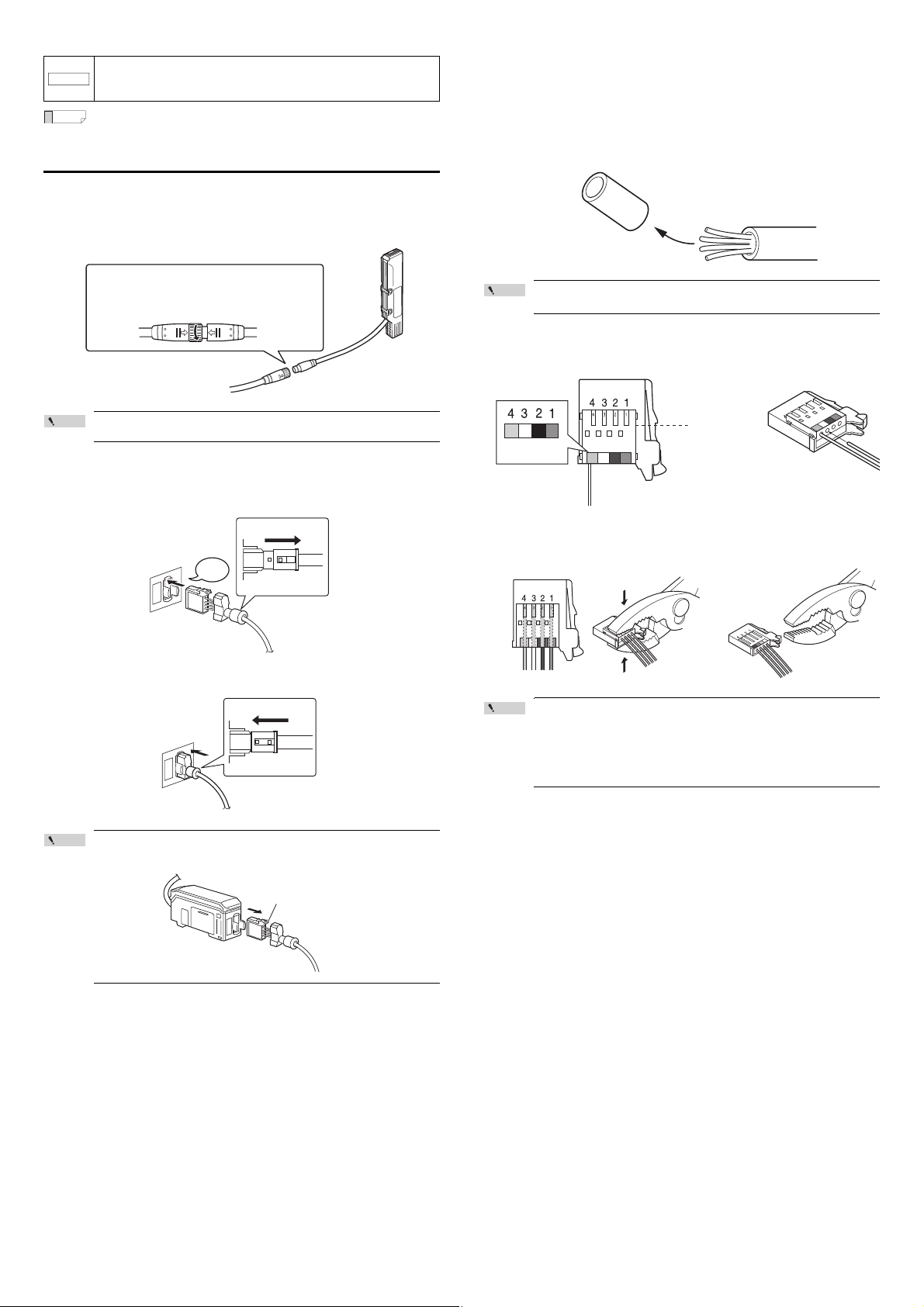
Connection and Wiring
Connecting the sensor head and amplifier
1 Attach the sensor head connection cables to the sensor head cable
Tighten the connectors securely by hand.
2 Attach the sensor head connection cable to the amplifier connector.
Remove the lock cover of the connector and insert it into the connectors of
amplifier until a clicking sound is heard.
Attaching the sensor head cable connector (OP-84338:
optional accessory)
Cut the sensor head connection cable to the required length and attach the new
connector to use the sensor.
1 Cut the cable to the required length and strip approx. 15 mm of
insulation from the end of the cable.
Point
Do not strip the core wire insulation.
2 Insert the wires into the connector holes of the matching color.
The cables should be inserted to the end and held in place.
3 Attach the lock cover to the connector to secure the cable.
When removing the sensor head connection cable, push in the
lock lever and pull it out.
3 Confirm that all wires are inserted to the specified position and
crimp them using pliers or a similar tool.
Point
After the connector is changed, connect it to the amplifier and
confirm normal operation.
If it does not operate normally, crimp the connector again with
pliers.
Once the connector is crimped, it cannot be reused.
E SK-1000 IM
6
Page 7
3. Basic Operations
Point
Power ON
PRP
LASER
BANK
0
1
2
3
HI
LO
R.V.
ANALOG
HI SHIFT
ZERO SHIFT
TIMING
LO
ALIGNMENT
QWV
GO
HOLD CALC
CHECK
Output polarity
Setting value
Description
npn
NPN output
pnp
PNP output
HOLD
HI
V
kV
ALARM
BANK
ZERO SHIFT
TIMING
TEMP %RH
HI LO R.V.
0
1
2
3
LO
GO
Analog output
Setting value
Description
off
Not output
0-5u
Analog output after the judgment value (P.V.) is
converted to the range from 0 to 5 V.
-5-5u
Analog output after the judgment value (P.V.) is
converted to the range from -5 to 5 V.
1-5u
Analog output after the judgment value (P.V.) is
converted to the range from 1 to 5 V.
aMpr
Analog output after the judgment value (P.V.) is
converted to the range from 4 to 20 mA.
HOLD
HI
V
kV
ALARM
BANK
ZERO SHIFT
TIMING
TEMP %RH
HI LO R.V.
0
1
2
3
LO
GO
HOLD
HI
V
kV
ALARM
BANK
ZERO SHIFT
TIMING
TEMP %RH
HI LO R.V.
0
1
2
3
LO
GO
HOLD
HI
V
kV
ALARM
BANK
ZERO SHIFT
TIMING
TEMP %RH
HI LO R.V.
0
1
2
3
LO
GO
HOLD
HI
V
kV
ALARM
BANK
ZERO SHIFT
TIMING
TEMP %RH
HI LO R.V.
0
1
2
3
LO
GO
HOLD
HI
V
kV
ALARM
BANK
ZERO SHIFT
TIMING
TEMP %RH
HI LO R.V.
0
1
2
3
LO
GO
HOLD
HI
V
kV
ALARM
BANK
ZERO SHIFT
TIMING
TEMP %RH
HI LO R.V.
0
1
2
3
LO
GO
HOLD
HI
V
kV
ALARM
BANK
ZERO SHIFT
TIMING
TEMP %RH
HI LO R.V.
0
1
2
3
LO
GO
R.V.
[
R.V.
]
ON
[HI]
ON
HI side setting value
LO side setting value
[LO]
ON
TEMP][%RH]
ON
[
TEMP
]
ON
Temperature
Temperature/Humidity
Humidity
[%RH]
ON
(1) Temperature/humidity display screen (6) R.V. display screen
(2) Temperature display screen (5) LO side setting value screen
(3) Humidity display screen (4) HI side setting value screen
Operations on the Main Screens
This chapter describes basic operations and settings for the SK Series.
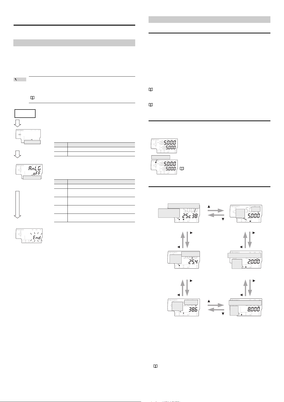
Operation When the Power is Turned on for the First Time
When the amplifier is turned on for the first time after the sensor head is
connected, the initial setting screen appears after a few seconds. Adjust the initial
settings according to the following procedure.
The initial setting is necessary for both the main unit and the expansion units when
they are added.
Once the initial setting is completed, the initial setting display will
not appear when the power is turned on the second time or
thereafter.
To change these settings, perform an initial reset.
"Initial Reset (Initialize)" (page 8)
1 Press S / T button to select the polarity of
judgment output and alarm output, and then
press [MODE] button.
[MODE] button
2 Press S / T button to select the type of
analog output and press [MODE] button.
(For SK-1000 only)
R.V. (Internal Measurement Value) and P.V. (Judgment Value)
This section describes R.V. (Internal Measurement Value) displayed on the sub
display (lower level) and P.V. (Judgment Value) displayed on the main display
(upper level).
R.V. (Internal Measurement Value)
R.V. (Internal Measurement Value) is the value displayed when a target is inserted
into the measurement range. Only the charge potential can be displayed.
* R.V. = Raw Value
P.V. (Judgment Value)
P.V. (Judgment Value) is the value to set the judgment output to ON/OFF
according to the tolerance setting value. Also, the analog output is output based
on the P.V.. Only the charge potential can be displayed.
* P.V. = Present Value
"Changing the Tolerance Values" (page 9)
The Judgment value (P.V.) and the Internal Measurement Value (R.V.) are typically
the same value. However, when the hold function, step-count filter, or the calculation
function is used, they will become different values.
"6. Hold Function" (page 12)
* The R.V. and P.V. cannot be displayed for the temperature and humidity.
Main Display (Upper Level)
The judgment value (P.V.) is shown on the main display.
The display varies according to the functions used such as Normal, Hold function,
and the Calculation function.
ALARM
kV
V
HOLD
HI
GO
LO
0
BANK
1
2
3
TEMP %RH
HI LO R.V.
[HOLD] ON
HOLD
HI
GO
LO
0
BANK
1
2
3
TEMP %RH
HI LO R.V.
Normal
The same value as the internal measurement value (R.V.) is
displayed as a judgment value (P.V.).
ZERO SHIFT
TIMING
When the hold function is used
ALARM
kV
V
The judgment value (P.V.) is held according to the hold
function settings.
ZERO SHIFT
"6. Hold Function" (page 12)
TIMING
Sub Display (Lower Level)
[MODE] button
3 After the setting is complete, [end] blinks
several times on the sub display and the main
screen appears.
4 Change other settings as necessary.
The sub display can be switched with the arrow buttons W / X Depending on the
type of displayed value, the sub display indicator [R.V. / TEMP / %RH / HI / LO]
lights up.
(1) Temperature/humidity display screen
The temperature and humidity detected by the sensor head are displayed.
(2) Temperature display screen
The temperature detected by the sensor head is displayed.
(3) Humidity display screen
The humidity detected by the sensor head is displayed.
(4) HI side setting value screen
The upper limit of the acceptable range (tolerance setting value) for the target
is displayed. This setting value can be changed. If the judgment value (P.V.)
exceeds the value set here, the HI judgment output turns on.
"Changing the Tolerance Values" (page 9)
7
E SK-1000 IM
Page 8
(5) LO side setting value screen
HOLD
HI
V
kV
ALARM
BANK
SET MODE
SELECT
ZERO SHIFT
ZERO SHIFT
TIMING
TEMP %RH
HI LO R.V.
0
1
2
3
LO
GO
SK-1000
Buttons used
HOLD
HI
V
kV
ALARM
BANK
ZERO SHIFT
TIMING
TEMP %RH
HI LO R.V.
0
1
2
3
LO
GO
HOLD
HI
V
kV
ALARM
BANK
ZERO SHIFT
TIMING
TEMP %RH
HI LO R.V.
0
1
2
3
LO
GO
PRP
LASER
BANK
0
1
2
3
HI
LO
R.V.
ANALOG
HI SHIFT
ZERO SHIFT
TIMING
LO
ALIGNMENT
QWV
GO
HOLD CALC
CHECK
Output polarity
Setting value
Description
npn
NPN output
pnp
PNP output
Setting value
Description
off
Not output
0-5u
Analog output after the judgment value (P.V.) is
converted to the range from 0 to 5 V.
-5-5u
Analog output after the judgment value (P.V.) is
converted to the range from -5 to 5 V.
1-5u
Analog output after the judgment value (P.V.) is
converted to the range from 1 to 5 V.
aMpr
Analog output after the judgment value (P.V.) is
converted to the range from 4 to 20 mA.
The lower limit of the acceptable range (tolerance setting value) for the target
is displayed. This setting value can be changed. If the judgment value (P.V.)
falls below the value set here, the LO judgment output turns on.
"Changing the Tolerance Values" (page 9)
(6) R.V. display screen
The internal measurement value (R.V.) is displayed. The displayed value is not
held even if a hold function is enabled.
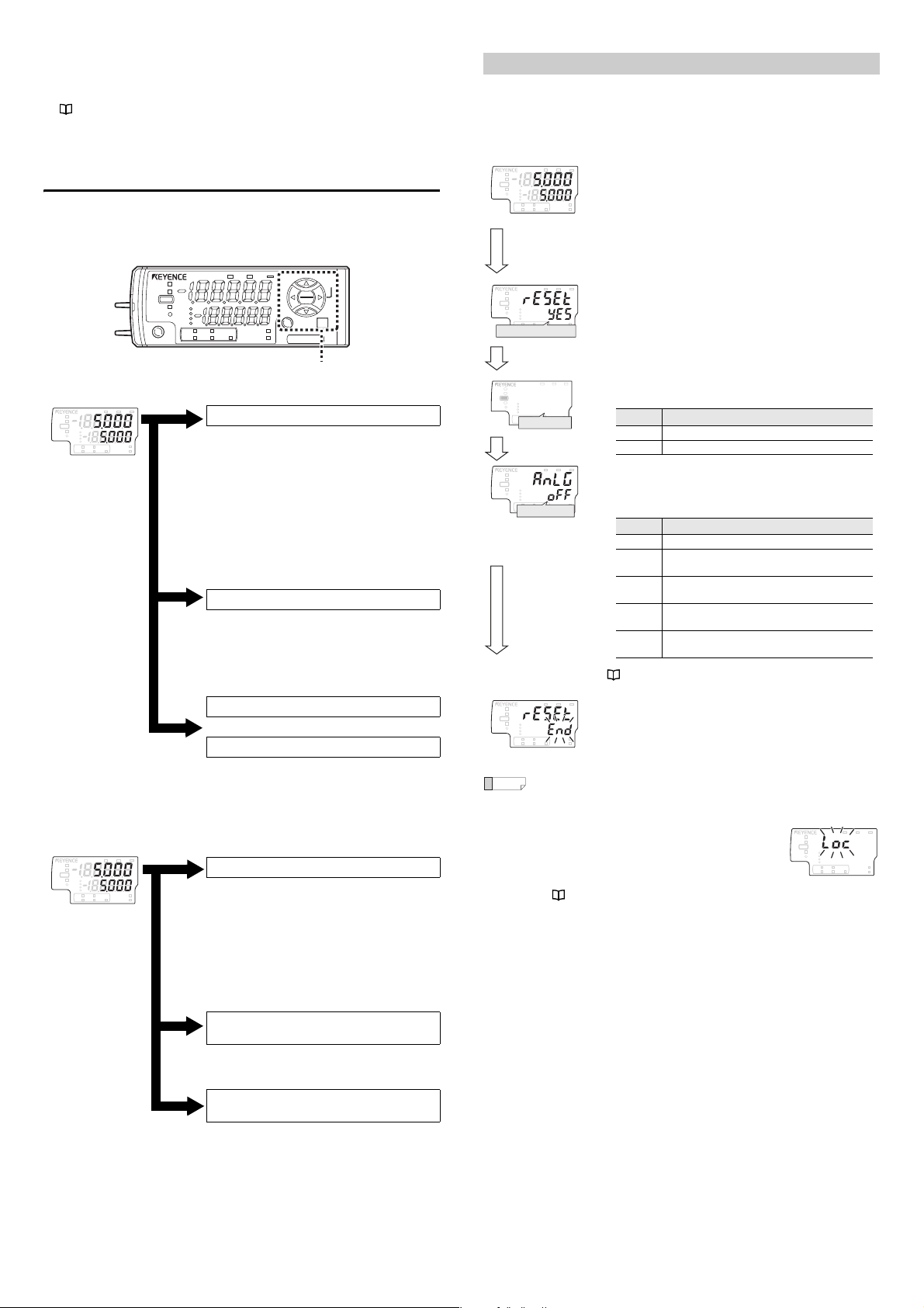
Setting Operations
This section explains the functions of the main screen and the functions of each
setting screen.
Functions Operable on the Main Screen
Main screen
Press W or X button.
Switching the sub display (lower level; page
7)
The internal measurement value (R.V.), HI
side setting value, LO side setting value,
temperature and humidity, temperature, or
humidity is displayed, and the settings can
be changed.
"Changing the Tolerance Values" (page 9)
Set the HI side tolerance setting value and
the LO side tolerance setting value. The value
is judged as HI, GO, or LO and is displayed
and output.
While pressing down [MODE], press S or T button.
"Bank Function (Registering Multiple
Tolerance Setting Values)" (page 9)
The HI side setting value, LO side setting
value, and shift target value can be saved in
up to four different banks, and the bank can
be switched.
Press [MODE] and S buttons for approx. 2 seconds.
or
Press [MODE] and S buttons for approx. 2 seconds.
"Key Lock Function" (page 10)
This function prevents unwanted button
operations during measurement.
Available Functions from the Main Screen
Main screen
Press [MODE] button for approx. 2 seconds.
"Basic Settings and Advanced Settings"
(page 10)
Basic settings
Configure basic settings such as the
measurement mode and the averaging rate.
Advanced settings
Configure more advanced settings such as
the hold function and the timing input in order
to use the unit in a wider range of
applications.
While pressing the [MODE] button, press the
[SET] button 5 times.
"Initial Reset (Initialize)" (page 8)
All settings, excluding the calibration
function, are initialized.
[While pressing the [MODE] button, press the
W button 5 times.
"Simulation Mode" (page 17)
You can use this function to check that the I/O
E SK-1000 IM
wires for control have been wired correctly.
Initial Reset (Initialize)
When an initial reset is performed, all settings, excluding the calibration function,
are initialized.
The judgment output's polarity and analog output setting can also be changed
through the same operation.
Main screen
ALARM
kV
V
HOLD
HI
GO
LO
0
BANK
1
2
3
ZERO SHIFT
TEMP %RH
HI LO R.V.
While pressing
the [MODE]
button, press the
[SET] button 5
times.
kV
V
HOLD
HI
GO
LO
0
BANK
1
2
3
ZERO SHIFT
TEMP %RH
HI LO R.V.
Performing the initial reset
[MODE] button
TIMING
TIMING
1 While pressing the [MODE] button on the
main screen, press the [SET] button 5 times.
[reset] is displayed on the main display (upper
level).
ALARM
2 Press S / T button to select [yes] and press
the [MODE] button.
If [no] is selected at this point, only the output
polarity and analog output settings can be changed
without performing the initial reset.
3 Press S / T button to select the output
polarity and press the [MODE] button.
[MODE] button
ALARM
kV
V
HOLD
HI
GO
LO
0
BANK
1
2
3
ZERO SHIFT
TEMP %RH
TIMING
HI LO R.V.
Analog output
[MODE]button
kV
V
HOLD
HI
GO
LO
0
BANK
1
2
3
ZERO SHIFT
TEMP %RH
TIMING
HI LO R.V.
• When buttons other than the S/T button and [MODE] button are
Reference
pressed during the initial reset procedure, the initial reset is
canceled and the screen in step 2 is restored.
• When you attempt to initialize the unit while
the key lock function is set, the screen shown
on the right appears and the initialization fails.
Cancel the key lock before attempting to
initialize the unit.
8
4 Press S / T button to select the analog
output and press the [MODE] button.
(For SK-1000 only)
"9. Analog output scaling" (page 14)
ALARM
5 After the initialization is complete, [end] blinks
several times on the sub display and the main
screen is restored.
"Key Lock Function" (page 10)
HOLD
HI
GO
LO
BANK
0
1
2
3
TEMP %RH
HI LO R.V.
ALARM
kV
V
ZERO SHIFT
TIMING
Page 9

Changing the Tolerance Values
Reference
Reference
Judgment indicator
HOLD
HI
V
kV
ALARM
BANK
ZERO SHIFT
TIMING
TEMP %RH
HI LO R.V.
0
1
2
3
LO
GO
[LO]
ON
HI side setting value
HOLD
HI
V
kV
ALARM
BANK
ZERO SHIFT
TIMING
TEMP %RH
HI LO R.V.
0
1
2
3
LO
GO
The tolerance values consist of the upper limit value (HI side setting value) and the
lower limit value (LO side setting value). By setting these values, judgments are
made in three levels: when the judgment value (P.V.) goes beyond the upper limit (HI
judgment), when the judgment goes beyond the lower limit (LO judgment) and
when the judgment is within the acceptable range (GO judgment). Subsequently,
the corresponding indicator and judgment output will be turned ON/OFF.
Judgme nt
Judgment output
HI GO LO HI GO LO
*1
Judgment indicator
HI ON OFF OFF Red OFF OFF
GO OFF ON OFF OFF Green OFF
LO OFF OFF ON OFF OFF Red
*3
Error
ON OFF ON Red OFF Red
*2
*1 When the state of judgment output is Normally Open (default value) ON/OFF
is reversed when the state is Normally Closed.
*2 "3. Output state" (page 11)
*3 "Error Displays and Corrective Actions" (page 20)
HOLD
HI
GO
LO
ZERO SHIFT
0
BANK
1
2
3
TEMP %RH
HI LO R.V.
V
ZERO SHIFT
TIMING
SELECT
SET MODE
SK-1000
kV
ALARM
When the setting "HI side setting value < LO side setting value" is
chosen, the judgment output is as follows.
• GO judgment output is not output regardless of the judgment value
(P.V.). (When "HI side setting value = LO side setting value =
judgment value (P.V.)" and hysteresis = 0.000, the GO judgment
output is turned on.)
• When the judgment value (P.V.) simultaneously exceeds the HI side
setting value and falls below the LO side setting value, the HI
judgment output and LO judgment output are output at the same
time.
Setting the tolerance
Zero Shift Function (Shifting the Internal Measurement Value (R.V.))
The internal measurement value (R.V.) is shifted (offset) to zero. The judgment
value (P.V.) is shifted (offset) as well.
The following two methods can be used.
• Press the [ZERO SHIFT] button (<1 second).
• Set the external input (zero shift input) to ON for 20 ms or more.*
* When the zero shift input is set for the external input 1 (pink wire), the zero shift
is enabled when the input is triggered.
"10. External input" (page 15)
Enabling the Zero Shift
When the following operation is performed on the main screen, the zero shift
indicator [ZERO SHIFT] lights up for approx. 0.5 second and the current internal
measurement value (R.V.) shifts to zero.
• Press the zero shift button [ZERO SHIFT] (<1 second).
• Turn ON the zero shift input of external input for 20 ms or more.
Point
• If the power is turned OFF after a zero shift is performed by
external input, the previous state before the zero shift function is
restored. If you wish to keep the shifted state of the internal
measurement value (R.V.) even after the power is turned OFF, set
the zero shift value memory function to ON.
"12. Zero shift value memory function" (page 16)
• When the internal measurement value (R.V.) is [-----], [FFFF], or
[-FFFF] - that is, when the value is too large (a value outside of
±500 V in near mode and a value outside of ±12.5 kV in far mode)
- the zero shift function cannot be used.
ALARM
kV
BANK
TEMP %RH
0
1
2
3
HI LO R.V.
V
ZERO SHIFT
TIMING
HOLD
HI
GO
LO
When the zero shift is performed by pressing the zero shift button, the
Reference
shifted state of the internal measurement value (R.V.) is preserved
even after the power is turned off.
This is the method to directly enter the tolerance setting value (HI side setting
value, LO side setting value).
1 Press the W / X button several times on the main screen. Then
display the HI side setting value on the sub display (lower level).
"Sub Display (Lower Level)" (page 7)
2 Press S / T button to set the HI side setting value.
Item Setting range Default value
HI side setting value -99.999 to 99.999 1.000
3
Press the X button once and display the LO side setting value on the
sub
display (lower level).
ALARM
kV
BANK
[LO]
ON
0
1
2
3
TEMP %RH
HI LO R.V.
V
ZERO SHIFT
TIMING
HOLD
LO side setting value
HI
GO
LO
4 Press S / T button to set the LO side setting value.
Item Setting range Default value
LO side setting value -99.999 to 99.999 -1.000
After setting, press W / X button to return the sub display to the original
display as necessary.
Canceling the Zero Shift (Reset)
When the following operation is performed on the main screen, the zero shift is
canceled and the internal measurement value (R.V.) returns to the previous state
(initial state) before the zero shift function is used.
• Press the zero shift button [ZERO SHIFT] for 2 seconds or more.
The following screen appears after operation.
Bank Function (Registering Multiple Tolerance Setting Values)
Using the bank function, you can register up to four patterns of specified tolerance
settings.
By using the bank function, multiple setting items registered beforehand can be
switched easily.
Settings Registered with each Bank
Settings Reference page
HI side setting value
LO side setting value
"Changing the Tolerance Values" (page 9)
As soon as the HI side setting value and the LO side setting value are
entered, the judgment and output begin with the new setting value.
9
E SK-1000 IM
Page 10
How to Switch Banks
HOLD
HI
V
kV
ALARM
BANK
ZERO SHIFT
TIMING
TEMP %RH
HI LO R.V.
0
1
2
3
LO
GO
Lock set
HOLD
HI
V
kV
ALARM
BANK
ZERO SHIFT
TIMING
TEMP %RH
HI LO R.V.
0
1
2
3
LO
GO
Lock canceled
1. rnG
2. AvE
3. out
4. dst
5. HLd
6. HLd
7. tiM
8. HYS
9. AnG
10. in
11. bnK
12. SFt
13. dSP
Banks can be switched by either of the methods below.
• Front panel commands on the amplifier.
• Use the external inputs (Bank A input, Bank B input)*
* If the bank switching method is set to external input, and bank A input or bank
B input is set for the external input, banks can be switched with the external
input.
"10. External input" (page 15)
"11. Bank switching method" (page 16)
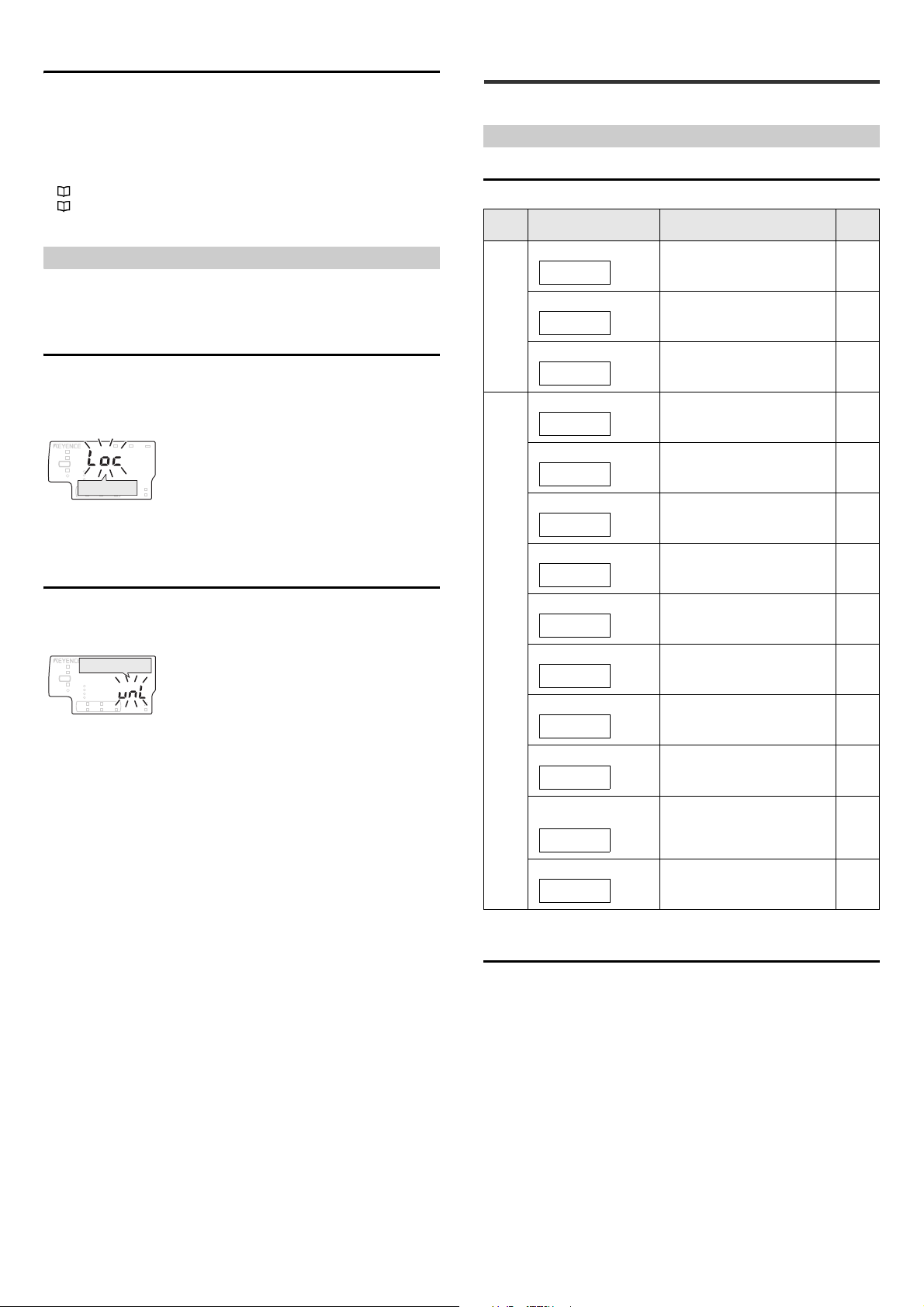
Key Lock Function
The key lock function prevents unwanted button operations during measurement.
When the key lock function is active, operations other than switching the main
screen and canceling the key lock function are disabled.
Starting the Key Lock
While pressing the [MODE] button on the main screen, press S or T button for 2
seconds or more.
After [Loc] blinks on the main display (upper level) for several seconds, the main
screen is restored.
4. Setting Various Functions
This chapter describes the various functions of the SK Series.
Basic Settings and Advanced Settings
List of Setting Items
The following items can be set.
Typ e Setting item Description
Basic
settings
1.Measurement range
2.Averaging rate
3.Output state
4.Distance setting
Set the measurement range. 11
Set the number of samples to average. 11
Select the output state (N.O./N.C.) of the
judgment output to turn ON/OFF
according to the judgment value.
Set the distance correction. 11
Reference
page
11
If buttons other than display switching button on the sub display (lower level) are
operated in the key-locked state, [Loc] is displayed on the main display (upper
level) and setting change operation is ignored.
Canceling the Key Lock (Unlock)
While pressing the [MODE] button, press S or T button for 2 seconds or more.
After [
unL] blinks on the sub display (lower level) for several seconds, the main
screen is restored.
5. Area scaling
6. Hold function
7.Timing input
8.Hysteresis
Advanced
9.Analog output scaling
settings
10.External input
11.Bank switching method
12.Zero shift value memory
function
13. Display digit
Set the area scaling. 12
Set the method to use in holding the
judgment value (P.V.)
Set the timing input type used for the
hold function.
Set the hysteresis value for the tolerance
setting value.
Set the analog output scaling for the
judgment value (P.V.).
Select the functions of the four external
inputs.
Set the bank switching method. 16
Set whether to store in the nonvolatile
memory (EEPROM) the state of the
display as shifted by the zero shift
function.
Set the number of displayed digits of the
judgment value (P.V.) and the internal
measurement value (R.V.).
12
14
14
14
15
16
16
E SK-1000 IM
Setting Screen
This section describes operations and the setting screen to modify the basic
settings and the detailed setting.
How to go to the setting screen
Press the [MODE] button for approx. 2 seconds on the main screen.
The setting screen appears.
Basic operations on the setting screen
Changing the setting value: S / T button
Go to the next setting item: [MODE] button or X button
Return to the previous setting item: W button
Skip the rest of the settings and finish: Press and hold the [MODE] button for
approx. 2 seconds.
Setting screen view
The setting item is displayed on the main display (upper level) and the setting
value is displayed on the sub display (lower level).
10
Page 11

HOLD
HI
V
kV
ALARM
BANK
ZERO SHIFT
TIMING
TEMP %RH
HI LO R.V.
0
1
2
3
LO
GO
HOLD
HI
V
kV
ALARM
BANK
ZERO SHIFT
TIMING
TEMP %RH
HI LO R.V.
0
1
2
3
LO
GO
HOLD
HI
V
kV
ALARM
BANK
ZERO SHIFT
TIMING
TEMP %RH
HI LO R.V.
0
1
2
3
LO
GO
HOLD
HI
V
kV
ALARM
BANK
ZERO SHIFT
TIMING
TEMP %RH
HI LO R.V.
0
1
2
3
LO
GO
HOLD
HI
V
kV
ALARM
BANK
ZERO SHIFT
TIMING
TEMP %RH
HI LO R.V.
0
1
2
3
LO
GO
HOLD
HI
V
kV
ALARM
BANK
ZERO SHIFT
TIMING
TEMP %RH
HI LO R.V.
0
1
2
3
LO
GO
Basic setting
Main screen
1.Measurement
range
2.Averaging
rate
[MODE]
Press for 2
seconds.
[MODE]
or X
[MODE]
or X
[MODE]
or X
Select the advanced
settings
Return to the
main screen.
To the 4. Distance
setting screen
(page 11) (page 11)
Basic setting
complete
3.Output state
[MODE]
or X
(page 11)
S or T
[MODE]
or X
HOLD
HI
V
kV
ALARM
BANK
ZERO SHIFT
TIMING
TEMP %RH
HI LO R.V.
0
1
2
3
LO
GO
HOLD
HI
V
kV
ALARM
BANK
ZERO SHIFT
TIMING
TEMP %RH
HI LO R.V.
0
1
2
3
LO
GO
HOLD
HI
V
kV
ALARM
BANK
ZERO SHIFT
TIMING
TEMP %RH
HI LO R.V.
0
1
2
3
LO
GO
HOLD
HI
V
kV
ALARM
BANK
ZERO SHIFT
TIMING
TEMP %RH
HI LO R.V.
0
1
2
3
LO
GO
HOLD
HI
V
kV
ALARM
BANK
ZERO SHIFT
TIMING
TEMP %RH
HI LO R.V.
0
1
2
3
LO
GO
HOLD
HI
V
kV
ALARM
BANK
ZERO SHIFT
TIMING
TEMP %RH
HI LO R.V.
0
1
2
3
LO
GO
HOLD
HI
V
kV
ALARM
BANK
ZERO SHIFT
TIMING
TEMP %RH
HI LO R.V.
0
1
2
3
LO
GO
HOLD
HI
V
kV
ALARM
BANK
ZERO SHIFT
TIMING
TEMP %RH
HI LO R.V.
0
1
2
3
LO
GO
HOLD
HI
V
kV
ALARM
BANK
ZERO SHIFT
TIMING
TEMP %RH
HI LO R.V.
0
1
2
3
LO
GO
HOLD
HI
V
kV
ALARM
BANK
ZERO SHIFT
TIMING
TEMP %RH
HI LO R.V.
0
1
2
3
LO
GO
HOLD
HI
V
kV
ALARM
BANK
ZERO SHIFT
TIMING
TEMP %RH
HI LO R.V.
0
1
2
3
LO
GO
Advanced settings
4.Distance
setting
[MODE]
or X
Advanced setting
complete
[MODE]
or X
5.Area scaling
[MODE]
or X
[MODE]
or X
8.Hysteresis
9.Analog output
scaling
10.External input
11.Bank switching
method
12.Zero shift value
memory function
(page 11) (page 12)
(page 14) (page 14) (page 14)
(page 15) (page 16) (page 16)
From the advanced
settings selection screen
[MODE]
or X
[MODE]
or X
[MODE]
or X
[MODE]
or X
[MODE]
or X
[MODE]
or X
[MODE]
or X
7.Timing input
Return to the
main screen.
13.Display digit
(page 16)
[MODE]
or X
6.Hold function
(page 12)
1. rnG
near
far
ib
2. Ave
3. Output state
NOTICE
3. out
4. dst
defLt
Usr
Usr
4. dst
25
U-dst
[MODE]
or
X
Usr
4. dst
100
U-dst
[MODE]
or
X
Set the output state (N.O./N.C.) of judgment output ON/OFF.
Item Description
Output state no (Normally Open), nC (Normally Closed) no
There are three judgment outputs:
• HI judgment output (Black wire)
• GO judgment output (Gray wire)
• LO judgment output (White wire)
The judgment output is turned ON/OFF according to the tolerance setting value.
"Changing the Tolerance Values" (page 9)
When Normally Open is set
Judgment
HI ON OFF OFF
GO OFF ON OFF
LO OFF OFF ON
*1
Error
"-----"
ON OFF ON
*2
OFF OFF OFF
Judgment output
HI GO LO
When Normally Closed is set
Judgment
HI OFF ON ON
GO ON OFF ON
LO ON ON OFF
*1
Error
"-----"
OFF ON OFF
*2
ON ON ON
Judgment output
HI GO LO
*1 "Error Displays and Corrective Actions" (page 20)
*2 When the judgment value (P.V.) is "-----".
Regardless of the output state setting, the judgment indicator on the sensor
Reference
amplifier only matches the judgment output when Normally Open is set.
Default
value
1. Measurement range
You can switch the measurement mode according to the voltage to be measured.
Switch the measurement mode to match the application.
Measurement range Description
High-precision mode
Wide-range mode
Ion balance mode
2. Averaging rate
Set the averaging of the data acquired at the sampling rate.
z Averaging rate
The average value is the moving average. If the measured values fluctuate, stable
measurements can be obtained by increasing the average count.
Averaging rate 1/2/4/8/16/64/256/1024/4096/16384 64
Item Description
Measurement can be performed in the range of 0 to
±2 kV and the reference distance for measurement
is 25 mm.
Measurement can be performed in the range of 0 to
±50 kV and the reference distance for
measurement is 100 mm.
The ion balance is measured. The measurement
reference distance is 25 mm.
(* An optional ion balance plate is required.)
Default
value
c
Default
value
4. Distance setting
Set the distance correction. When the sensor head cannot be installed at the
reference distance (25 mm for "near" and 100 mm for "far"), you can correct the
measured value by setting the installation distance.
Distance setting Description
Default setting
User setting
The distance will not be corrected. c
The distance will be corrected. Set the installation
distance (the setting range).
If the measurement range is "near:" 5 to 50
If the measurement range is "far:" 60 to 120 (unit:
mm)
Distance setting screen
When set to the default setting, [defLt], the following screens are skipped.
When you set this to the user setting, [Usr], the distance setting screen is displayed.
z User setting, [Usr]
• If the measurement range is [near]
4.Distance setting Distance
Press the S and T buttons to specify the
distance. (Setting range: 5 to 50)
• If the measurement range is [far]
4.Distance setting Distance
Press the S and T buttons to specify the
distance. (Setting range: 60 to 120)
Decreasing the installation distance makes the measurement
range narrower.
11
E SK-1000 IM
Default
value
Page 12
5. Area scaling
5. ScL
HOLD
HI
V
kV
ALARM
BANK
ZERO SHIFT
TIMING
TEMP %RH
HI LO R.V.
0
1
2
3
LO
GO
Press the S/T buttons and specify the correction value.
(Setting range: 0.10 to 1.50)
0
5
10
15
20
25
30
35
40
45
50
-200 -150 -100 -50 0 50 100 150
200
1.0
0.9
0.8
0.7
0.6
1.01.0
0.90.9
0.80.8 0.70.7 0.60.6
Measurement area [mm]
Distance to the target [mm]
60
70
80
90
100
110
120
-450 -350 -250 -150 -50 50 15 0 25 0 350 45 0
1.3
1.2
1.1
1
0.9
0.7
1.31.3
1.2
1.2
1.11.1
0.90.9
0.70.7
11
Measurement area [mm]
Distance to the target [mm]
60
70
80
90
100
110
120
-450 -350 -250 -150 -50 50 15 0 25 0 350 45 0
1.3
1.2
1.1
1
0.9
0.7
1.31.3
1.2
1.2
1.1
1.1
0.90.9
0.70.7
1
1
Measurement area [mm]
Distance to the target [mm]
Correction
value is 1.1.
The measurement area ranging from
-200 mm to +200 mm covers
φ400 mm.
60
70
80
90
100
110
120
-450 -350 -250 -150 -50 50 150 250 35 0 450
1.3
1.2
1.1
1
0.9
0.7
1.3
1.2
1.1
1.3
1.2
1.1
0.9
0.7
1
0.9
0.7
1
Measurement area [mm]
Distance to the target [mm]
The measurement area ranging from
-390 mm to +390 mm covers φ780 mm.
Correction
value is 1.3.
Reference
6. HLd
HOLD
HI
V
kV
ALARM
BANK
ZERO SHIFT
TIMING
TEMP %RH
HI LO R.V.
0
1
2
3
LO
GO
[HOLD] ON
S-H
P-H
b-H
A-H
Auto.P
Auto.b
Auto.A
S-H
Display value
Time
Judgment value (P.V.)
Internal measurement value (R.V.)*
2
Timing Input
ON
OFF
Power ON or
Reset input *
1
After the power is turned on or reset is input, the judgment value (P.V.) is
[- - - - -] until the timing input is first turned ON.
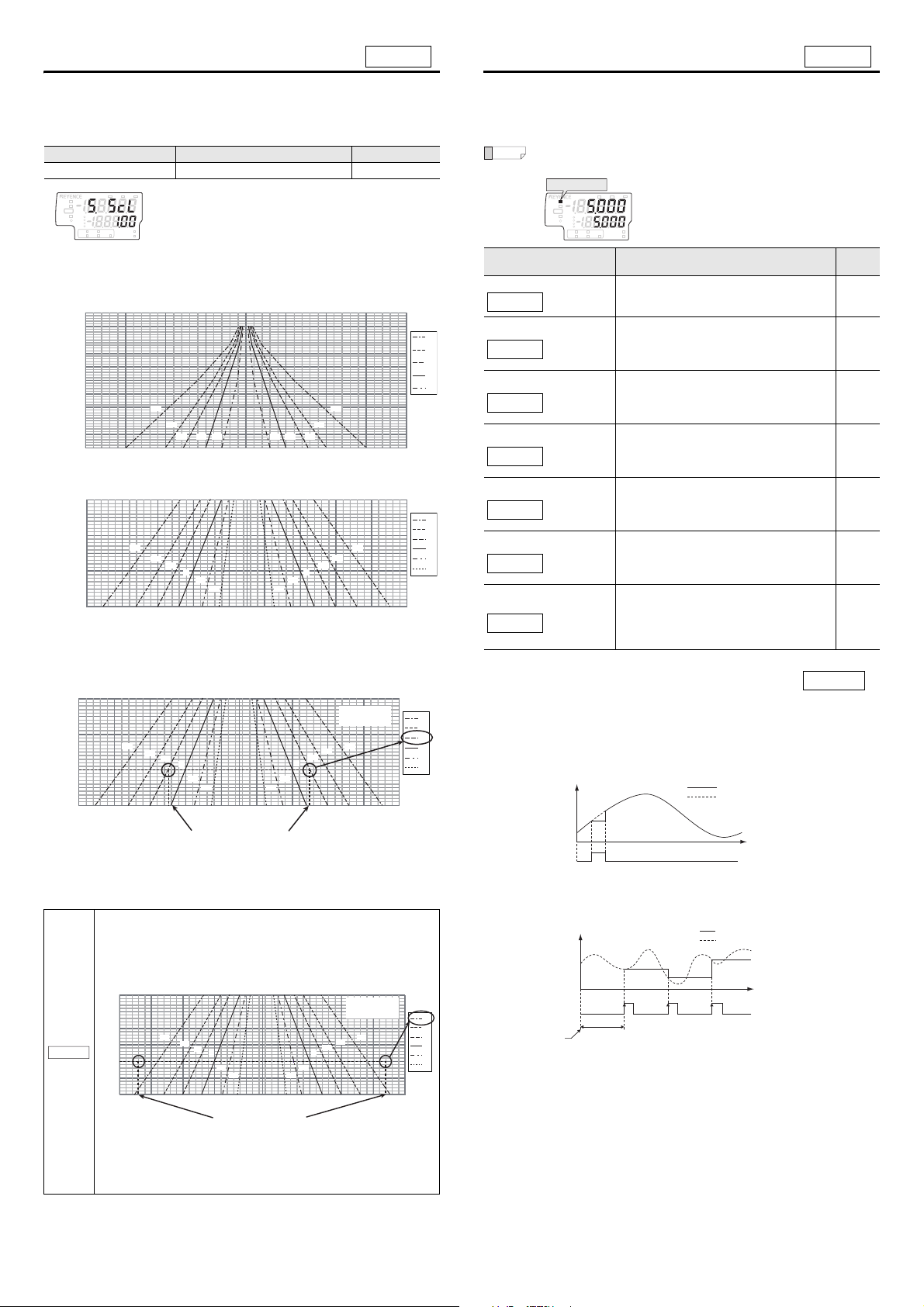
6. Hold Function
This function configures the settings related to area scaling. The area scaling
function corrects errors in the measured value due to size differences of
measurement targets by setting a correction value according to the size of the
target.
Item Setting range initial value
Area scaling 0.10 to 1.50 1.00
Refer to the correction table shown below to setting the correction value.
z Area scaling correction table
(1) High-precision mode
(2) Wide-range mode
[How to use the correction table and setting example]
Take a wide-range mode as an example for setting a correction value where the
distance to the target is 100 mm and the size of target is φ400 mm.
In this case, use the correction table for the wide-range mode.
The hold method is set for the judgment value (P.V.).
Functions other than "Auto peak hold", "Auto bottom hold" and "Auto absolute
value hold" require the use of the external input (timing input).
While the judgment value (P.V.) is held, the hold indicator on the sensor
amplifier lights up.
Hold function Description
Sample hold
Peak hold
Bottom hold
Absolute value hold
Auto peak hold
Auto bottom hold
When the timing input is turned ON, the judgment
value (P.V.) is held.
"Sample hold" (page 12)
The maximum value of the specified period
(sampling period) is held as the j udgment value
(P.V.).
"Peak hold" (page 13)
The minimum value of the specified period
(sampling period) is held as the j udgment value
(P.V.).
"Bottom hold" (page 13)
Within the specified period (sampling period), the
absolute value of the maximum measured value is
held as the judgment value (P.V.).
"Absolute value hold" (page 13)
Until the hold-reset input is turned ON, the
maximum value is held as the judgment value (P.V.).
External input is not necessar y.
"Auto peak hold" (page 13)
Until the hold-reset input is turned ON, the minimum
value is held as the judgment value (P.V.).
External input is not necessar y.
"Auto bottom hold" (page 13)
Until the hold-reset input is turned ON, the absolute
Auto absolute value hold
value of the maximum measured value is held as
the judgment value (P.V.).
External input is not necessar y.
"Auto absolute value hold" (page 14)
Default
Sample hold
When the timing input is turned ON, the judgment value (P.V.) is held.
value
c
The 100 mm on the vertical axis and 200 mm and -200 mm on the horizontal axis
make two intersecting points, crossing the lines marked with the S symbol, which
indicate a correction value of 1.1. So, input 1.1 into the amplifier unit.
• When the measurement target is larger than the outermost lines
of the correction table:
Example: In wide-range mode, with a distance of 100 mm to the
target, and a target size of φ780 mm, if the target is larger than the
outermost lines indicating the correction value of 1.3, set the
correction value to 1.3.
NOTICE
E SK-1000 IM
The same is true when using high-precision mode. If the target is
larger than the outermost lines indicating a correction value of
1.0, set the correction value to 1.0.
z When "Level" is set for "7. Timing input" (page 14)
The judgment value (P.V.) is held only while the timing input is ON.
Display value
Timing Input
OFF
ON
Judgment value (P.V.)
Internal measurement value (R.V.)*
Time
1
z When "Edge" is set for "7. Timing input" (page 14)
The judgment value (P.V.) is held in between rising edges of the timing input.
12
Page 13

Peak hold
P-H
Display value
Time
Timing Input
Sampling period Sampling periodSampling period
ON
OFF
Power ON or
Reset input *
1
After the power is turned on or reset is input, the judgment value (P.V.) is
[- - - - -] until the timing input is first turned ON.
Judgment value (P.V.)
Internal measurement value (R.V.)*
2
b-H
Display value
Time
Timing Input
Sampling period Sampling periodSampling period
ON
OFF
Power ON or
Reset input *
1
After the power is turned on or reset is input, the judgment value (P.V.) is
[- - - - -] until the timing input is first turned ON.
Judgment value (P.V.)
Internal measurement value (R.V.)*
2
Display value
Time
Timing Input
Sampling period Sampling period Sampling period
ON
OFF
Power ON or
Reset input *
1
After the power is turned on or reset is input, the judgment value (P.V.) is
[- - - - -] until the timing input is first turned ON.
Judgment value (P.V.)
Internal measurement value (R.V.)*
2
A-H
Absolute value-hold value
Display value
Time
Timing Input
ON
0
OFF
Power ON or
Reset input
Sampling period Sampling period Sampling period
After the power is turned on or reset is input, the judgment value (P.V.) is
[- - - - -] until the timing input is first turned ON.
Measurement value
Auto.P
Auto peak hold value
Display value
Time
Timing Input
ON
OFF
Reset input
ON
OFF
Measurement value
Auto.b
Auto bottom hold value
Display value
Time
Timing Input
ON
OFF
Reset input
ON
OFF
Measurement value
The maximum value of the specified period (sampling period) is held as a
judgment value (P.V.).
z When "Level" is set for "7. Timing input" (page 14)
When the timing input is turned ON, the maximum value of the internal
measurement value (R.V.) during the sampling period is held as the judgment
value (P.V.). When the timing input is turned OFF, the next sampling period begins.
Display value
Judgment value (P.V.)
Internal measurement value (R.V.)*
2
Absolute value hold
Within the specified period (sampling period), the absolute value of the maximum
value of the measured value is held as the judgment value (P.V.).
z When "Level" is set for "7. Timing input" (page 14)
When the timing input is turned ON, the maximum absolute value of the internal
measurement value (R.V.) during the sampling period is held as the judgment
value (P.V.). When the timing input is turned OFF, the next sampling period begins.
Time
Timing Input
Power ON or
Reset input *
Sampling period Sampling periodSampling period
ON
OFF
1
After the power is turned on or reset is input, the judgment value (P.V.) is
[- - - - -] until the timing input is first turned ON.
z When "Edge" is set for "7. Timing input" (page 14)
When the timing input is turned ON, the maximum value of the internal
measurement value (R.V.) during the sampling period is held as the judgment
value (P.V.). Also, when the timing input is turned ON, the next sampling period
begins.
Bottom hold
The minimum value of the specified period (sampling period) is held as a
judgment value (P.V.).
z When "Level" is set for "7. Timing input" (page 14)
When the timing input is turned ON, the minimum value of the internal
measurement value (R.V.) during the sampling period is held as the judgment
value (P.V.). When the timing input is turned OFF, the next sampling period begins.
z When "Edge" is set for "7. Timing input" (page 14)
When the timing input is turned ON, the maximum absolute value of the internal
measurement value (R.V.) during the sampling period is held as the judgment
value (P.V.). Also, when the timing input is turned ON, the next sampling period
begins.
Timing Input
Power ON or
Reset input
Display value
ON
OFF
Measurement value
Absolute value-hold value
Sampling period Sampling period
After the power is turned on or reset is input, the judgment value (P.V.) is
[- - - - -] until the timing input is first turned ON.
Sampling period
Time
Auto peak hold
Until the reset input is turned ON, the maximum value is held as the judgment
value (P.V.). External input is not necessary.
z When "Edge" is set for "7. Timing input" (page 14)
When the timing input is turned ON, the minimum value of the internal
measurement value (R.V.) during the sampling period is held as the judgment
value (P.V.). Also, when the timing input is turned ON, the next sampling period
begins.
Auto bottom hold
Until the reset input is turned ON, the minimum value is held as the judgment
value (P.V.). External input is not necessary.
13
E SK-1000 IM
Page 14

Auto absolute value hold
Reference
Reference
Auto.A
7. tiM
8. HYS
Time
Hysteresis
Hysteresis
Judgment value (P.V.)
HI side setting value
LO side setting value
ON
OFF
ON
OFF
ON
OFF
HI judgment output
GO judgment output
LO judgment output
9. AnG
dEFLt
Free
(V)
5
1
Lower limit Upper limit
Judgment
value
(P.V.)
Output upper
limit
Output lower
limit
HOLD
HI
V
kV
ALARM
BANK
ZERO SHIFT
TIMING
TEMP %RH
HI LO R.V.
0
1
2
3
LO
GO
HOLD
HI
V
kV
ALARM
BANK
ZERO SHIFT
TIMING
TEMP %RH
HI LO R.V.
0
1
2
3
LO
GO
HOLD
HI
V
kV
ALARM
BANK
ZERO SHIFT
TIMING
TEMP %RH
HI LO R.V.
0
1
2
3
LO
GO
HOLD
HI
V
kV
ALARM
BANK
ZERO SHIFT
TIMING
TEMP %RH
HI LO R.V.
0
1
2
3
LO
GO
9.Analog Output
Scaling
Upper-limit setting
screen
Lower-limit setting
screen
[MODE]
or X
10.External Input
[MODE]
or X
[MODE]
or X
Until the hold-reset input is turned ON, the maximum absolute value of the
measured value is held as the judgment value (P.V.). External input is not
necessary.
Display value
b
a
0
a
c
b
Auto-absolute value-hold value
c
Measurement value
Time
z Relation of voltage and analog output in default state (dEFLt)
Measurement range Upper limit Lower limit
NEAR 5.000 -5.000
FAR 50. 000 -50.000
The upper and lower limits for the different selections of analog outputs are as
follows.
Analog setting Output upper limit Output lower limit
OFF Not output
0-5v 5 V 0 V
-5-5v 5 V -5 V
1-5v 5 V 1 V
AMPr 20 mA 4 mA
Timing Input
Reset input
OFF
OFF
ON
ON
7. Timing input
Set the external input (timing input) operation used for "6. Hold Function" (page
12).
If "Auto peak hold," "Auto bottom hold," or "Auto absolute value hold" is set, this
item is skipped.
Item Description
Timing input LeveL (Level), edGe (Edge) LEvEL
Default
value
For details, refer to the "6. Hold Function" (page 12).
8. Hysteresis
Set the hysteresis for the tolerance setting value.
If the judgment value (P.V.) fluctuates close to the tolerance setting value, causing
the judgment output to repeatedly turn ON and OFF, increase the hysteresis value
to stabilize the judgment output.
Item Description
Default
value
Hysteresis 0.000 to 99.999 0.100
Above is the timing chart for when the judgment output state is
Normally Open (default value). ON/OFF is reversed for Normally Close.
9. Analog output scaling
The analog output scaling for the judgment value (P.V.) is set.
If the analog output is set to no output, this screen is skipped.
"Operation When the Power is Turned on for the First Time" (page 7)
"Initial Reset (Initialize)" (page 8)
Analog output scaling Description
Default setting
Scaling is not performed. c
Default
value
Upper limit setting screen and lower limit setting screen
When set to the default state [dEFLt], the following screens will be skipped.
When set to free range, the upper limit setting and lower limit setting screens will
appear.
z For free range (FrEE)
Press S / T button on each setting screen to specify the upper limit and the lower
limit.
z Setting range for analog output scaling
If free range is selected for the analog output scaling state, the upper limit and
lower limit can be set within the range shown below.
Measurement range Description Default value
Upper limit -99.999 to 99.999 10.000
Lower limit -99.999 to 99.999 -10 .000
Analog Output Accuracy
The analog output can be selected from ± 5 V, 1 to 5 V, 0 to 5 V or 4 to 20 mA.
Voltage output Current output
Output range
± 5 V
(Full scale 10 V)
Output resistance 100 Ω -
Maximum load resistance - 350 Ω
Repeatability ± 1 mV ± 1.5 μA
Accuracy in respect to display ± 0.05% of F.S. ± 0.25% of F.S.
Temperature characteristics ± 0.005% of F.S./°C ± 0.01% of F.S./°C
Refresh rate
*1
Same as sensor head sampling rate
*1 The averaging is as follows for averaging greater than 1024 times:
1024 times: Sampling rate x 4
2048 times: Sampling rate x 8
4096 times: Sampling rate x 16
4 to 20 mA
(Full scale 16 mA)
Free range
Example 1: Lower limit < Upper limit
(Analog output 1 to 5 V)
(V)
Output upper
limit
Output lower
limit
E SK-1000 IM
5
1
If Upper limit = Lower limit is set, the analog output is as follows:
Judgment value (P.V.) < Upper limit: Analog output lower limit (1V in
the case of 1V to 5V output range)
Judgment value (P.V.) > Upper limit: Analog output upper limit (5V in
the case of 1V to 5V output range)
Lower limit Upper limit
Scaling is performed. The analog output range can
be changed by specifying the upper limit and lower
limit of the judgment value (P.V.).
Example 2: Lower limit > Upper limit
(Analog output 1 to 5 V)
Judgment
value
(P.V.)
14
Page 15

10. External input
Reference
10. in
dEFLt
Usr
HOLD
HI
V
kV
ALARM
BANK
ZERO SHIFT
TIMING
TEMP %RH
HI LO R.V.
0
1
2
3
LO
GO
HOLD
HI
V
kV
ALARM
BANK
ZERO SHIFT
TIMING
TEMP %RH
HI LO R.V.
0
1
2
3
LO
GO
HOLD
HI
V
kV
ALARM
BANK
ZERO SHIFT
TIMING
TEMP %RH
HI LO R.V.
0
1
2
3
LO
GO
HOLD
HI
V
kV
ALARM
BANK
ZERO SHIFT
TIMING
TEMP %RH
HI LO R.V.
0
1
2
3
LO
GO
HOLD
HI
V
kV
ALARM
BANK
ZERO SHIFT
TIMING
TEMP %RH
HI LO R.V.
0
1
2
3
LO
GO
HOLD
HI
V
kV
ALARM
BANK
ZERO SHIFT
TIMING
TEMP %RH
HI LO R.V.
0
1
2
3
LO
GO
10.External Input External input 1
setting screen
External input 2
setting screen
External input 3
setting screen
External input 4
setting screen
11.Bank switching
method
[MODE]
or X
[MODE]
or X
[MODE]
or X
[MODE]
or X
[MODE]
or X
Internal measurement
value (R.V.)
Max. 20 ms
Min. 20 msMin. 20 ms
R.V. before shift R.V. after shift
ON
OFF
Zero shift input
Judgment value
(P.V.) judgment
output
T1
Min. 20 ms
Min. 20 ms
Before resetting [-----]
ON
OFF
Reset input
Max. 2 msMax. 2 ms
Min. 2 msMin. 2 ms
ON
OFF
Max. 2 ms
Sampling does not start Sampling period Sampling starts
Previous result
Judgment value
(P.V.) judgment
output
Timing Input
Judgment value
(P.V.) judgment
output
Max. 2 msMax. 2 ms
Min. 2 msMin. 2 ms
ON
OFF
Timing Input
Sampling period 1
Sampling period 1 result Sampling period 2 resultPrevious result
Sampling period 2 Sampling period 3
Judgment value
(P.V.) judgment
output
Max. 8 ms
Max. 20 ms
Max. 20 ms
Min. 20 ms
ON
OFF
Bank A input
ON
OFF
Bank B input
Max. 20 ms
Bank 1 Bank 2 Bank 3Bank 0
In this example, after 8 ms have passed, Bank A
and Bank B are judged as OFF and operation at
Bank 0 may be performed.
You can select functions to be assigned to four external inputs (External input 1 to
4).
External input Description
Default setting
User setting
Functions for the external inputs remain the same
as the factory default setting.
Functions for the external inputs are changed from
Default
value
c
the factory default setting.
External input setting screen
When the user setting is set, each function of the external input 1 to 4 can be set.
Functions that can be set differ for each external input. (When the default is set,
these four screens are skipped.)
Timing Input
When the timing input is turned ON while using the hold function, the judgment
value (P.V.) is held.
z Timing chart
• When Sample hold is set
"Timing Input" (page 15) setting: "Level"
Measuring period Measuring period
Judgment value
(P.V.) judgment
output
Timing Input
OFF
ON
"Timing Input" (page 15) setting: "Edge"
Hold released
Sample hold
Max. 2 msMax. 2 msMax. 2 ms
Min. 2 msMin. 2 ms
Press S / T button on each setting screen to specify functions
External Input 1 (Pink wire) External Input 2 (Yellow wire)
Setting
value
Shift
bnK-a
bnK-b
off
Description
Zero shift input
Bank A input
Bank B input
Not used
Default
value
c reset
Setting
value
bnK-a
bnK-b
off
Description
Reset input
Bank A input
Bank B input
Not used
Default
value
External input 3 (Pink/Purple wire) External Input 4 (Purple wire)
Setting
value
tiMnG
bnK-a
bnK-b
off
Description
Timing Input
Bank A input
Bank B input
Not used
When the same function is selected for multiple external inputs, the
inputs function according to OR operation.
Default
value
c bnK-a
Setting
value
bnK-b
off
Description
Bank A input
Bank B input
Not used
Default
value
Zero shift input
When the zero shift input is set to ON, the internal measurement value (R.V.) is
shifted (offset) to the selected shift target value.
z Timing chart
Judgment value
(P.V.) judgment
output
Timing Input
OFF
ON
Sample holdSample hold Sample hold
Max. 2 msMax. 2 msMax. 2 ms
Min. 2 msMin. 2 ms
• When Peak hold, Bottom hold or Absolute value hold is set
"Timing Input" (page 15)setting: "Level"
c
c
"Timing Input" (page 15) setting: "Edge"
z Minimum Input Time
ON time: 2 ms
OFF time: 2 ms
z Minimum Input Time
ON time: 20 ms
OFF time: 20 ms
Reset input
When the reset input is turned ON while using the hold function, the judgment
value (P.V.) in the held state is canceled and the value becomes [-----].
z Timing chart
z Minimum Input Time
ON time: 20 ms
OFF time: 20 ms
T1 = Input response delay (20 ms max.) + reset time*
* Reset time (judgment output, analog output) = Sampling period × (averaging
rate + 2)
Bank A input/Bank B input
By combining the ON/OFF status of bank A input and bank B input, you can
switch between banks.
z Timing chart
When the judgment value (P.V.) is held using the hold function, the
Reference
judgment value (P.V.) remains held even if the ON/OFF status of bank A
input or bank B input is switched. However, the judgment output will
change according to the HI/LO setting value of the new bank.
z Minimum Input Time
ON time: 20 ms
OFF time: 20 ms
15
E SK-1000 IM
Page 16

11. Bank switching method
Reference
Reference
11. bnK
btn
in
HOLD
HI
V
kV
ALARM
BANK
ZERO SHIFT
TIMING
TEMP %RH
HI LO R.V.
0
1
2
3
LO
GO
HOLD
HI
V
kV
ALARM
BANK
ZERO SHIFT
TIMING
TEMP %RH
HI LO R.V.
0
1
2
3
LO
GO
HOLD
HI
V
kV
ALARM
BANK
ZERO SHIFT
TIMING
TEMP %RH
HI LO R.V.
0
1
2
3
LO
GO
HOLD
HI
V
kV
ALARM
BANK
ZERO SHIFT
TIMING
TEMP %RH
HI LO R.V.
0
1
2
3
LO
GO
Bank indicator
Bank indicator
Bank indicator
Bank indicator
<While bank 0 is
selected>
<While bank 1 is
selected>
<While bank 2 is
selected>
<While bank 3 is
selected>
BANK 0 lights
BANK 1 lights
BANK 2 lights
BANK 3 lights
Press T while holding
down the [MODE] button.
Press T while holding
down the [MODE] button.
Press T while holding
down the [MODE] button.
Press T while
holding down the
[MODE] button.
HOLD
HI
V
kV
ALARM
BANK
ZERO SHIFT
TIMING
TEMP %RH
HI LO R.V.
0
1
2
3
LO
GO
12. SFt
13. dSP
12. Zero shift value memory function
Set whether to switch the bank with the amplifier buttons or with external inputs.
Bank switching method Description
Switching with buttons
Switching with external input
The banks are switched with the amplifier buttons. c
The banks are switched only by turning ON/OFF the
bank A input or bank B input set in "10. External
input".
Default
value
* If switching with buttons is selected, the bank can be switched only with the
amplifier buttons.
If switching with external input is selected, the bank can be switched only by
the external inputs.
Switching the bank with button operations
Press the S / T button while holding down the [MODE] button on the main
screen.
The bank will switch, and the bank indicator [BANK0 to 3] will light according to
the selected bank.
To save the zero shift performed with the external input, change the setting for the
nonvolatile memory (EEPROM) to save the shifted value.
When the zero shift is performed with the sensor amplifier button operation, it is
saved on the nonvolatile memory (EEPROM) regardless of the setting.
Point
If the data is written in the nonvolatile memory (EEPROM) over 1
million times, the error message is displayed and the setting may
not be saved any more. (It is still possible to obtain a
measurement value.)
For such cases as when a PLC frequently executes a zero shift,
and it is not necessary to store it in the nonvolatile memory
(EEPROM), it is recommended to turn this setting OFF.
Zero shift value memory Description
OFF
Do not save on the nonvolatile memory (EEPROM) c
ON
Save on the nonvolatile memory (EEPROM)
Default
value
13. Displayed digits
Set the number of digits for the judgment value (P.V.) and the internal
measurement value (R.V.) to display on the sensor amplifier.
Displayed digits Description
Operations are performed such as to maintain a
dEFLt
three-digit display. The unit is automatically
switched between V and kV and the decimal point
position is automatically switched.
0.001 3 decimal places
0.01 Truncate the 3rd decimal place
0.1 Truncate the 2nd decimal place
1 Truncate the 1st decimal place
Default
value
c
• If the S button is pressed while holding down the [MODE] button,
the banks will change in the reverse direction.
• The banks cannot be switched with buttons if the bank switching
method is set to external input. If the banks are switched with
buttons, the following is displayed.
Switching banks by external input
When the Bank A input and Bank B input are set for the external inputs, the bank
can be switched using the external inputs.
1 The banks are switched with the ON/OFF combination of the bank A
input and bank B input.
• The bank input must be held 20 ms or longer.
• The combinations of bank A input and bank B input are shown in the
following table.
Bank Bank A input Bank B input
Bank 0 OFF OFF
Bank 1 ON OFF
Bank 2 OFF ON ON: Short-circuited
Bank 3 ON ON OFF: Open
If the external input is not set to bank A or bank B, it is regarded as
OFF.
(Example) If only Bank A input is set for the external input, only two
banks (bank 0 and bank 1) can be selected using the
external input.
2 The bank switching method must be set to external input.
E SK-1000 IM
16
Page 17
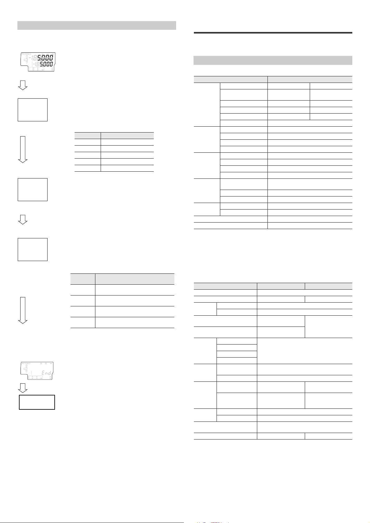
Simulation Mode
HOLD
HI
V
kV
ALARM
BANK
ZERO SHIFT
TIMING
TEMP %RH
HI LO R.V.
0
1
2
3
LO
GO
off
51.out
Setting value Description
OFF No signal is output.
HI The HI signal is output.
GO The GO signal is output.
LO The LO signal is output.
ALM The alarm signal is output.
----
52.in
Hi
53.AnG
Setting
value
Description
Hi
The upper limit of the analog output is
generated.
Mid
The middle value of the analog output is
generated.
Lo
The lower limit of the analog output is
generated.
Err
The output value when an error occurs is
output.
HOLD
HI
V
kV
ALARM
BANK
ZERO SHIFT
TIMING
TEMP %RH
HI LO R.V.
0
1
2
3
LO
GO
Return to the
main screen.
You can use this function to check that the I/O control cable has been wired
correctly.
Main screen
1 On the main screen, while pressing the
[MODE] button, press the W button five times.
[51.out] is displayed on the main display (upper
While pressing
the [MODE]
button, press the
W button five
times.
level).
2 Use the S/T buttons to display the signal that
you want to output in the sub display (lower
level). The signal will be output when it is
displayed. Press the [MODE] button to
proceed to the next step.
[MODE] button
3 When you turn ON external input 1 to external
input 4, the corresponding part of the display
will change from [_] to [o].
From the right, the parts correspond to external
inputs 1, 2, 3, and 4.
Press the [MODE] button to proceed to the next step.
[MODE] button
(Example) [___o] indicates that external input 1 is
on.
[o_o_] indicates that external inputs 2
and 4 are on.
4 The upper limit, middle value, and lower limit
of the analog output are generated. This is not
displayed when the analog output is turned
OFF. Press the [MODE] button to proceed to
the next step.
[MODE] button
(Example) When the analog output setting is 0 to 5 V
5 V is output for Hi, 2.5 V is output for Mid,
0 V is output for Lo, and 5.5 V is output for
Err.
5 [END] is displayed on the sub display (lower
level). Press the [MODE] button to complete
the procedure and return to the main screen.
5. Specifications
This chapter describes the specifications, circuit diagrams, and dimensions of the
SK Series.
Specifications
Sensor head
Model SK-050
Measurement mode High precision Wide range
Reference distance for
Electrification
potential
measurement
Temperature
measurement
Humidity
measurement
Ion balance
measurement
mode
Environmental
resistance
Materials Main body case: PC, metal part: SUS, cable: PVC
Weight Approx. 35 g
*1 Even in the measurement area, if the distance to the detection target is smaller than the
reference distance, measurement cannot be performed up to the upper limit of the
measurement range.
*2 When measured an average of 256 times, this value is ±100 V or less in high-precision
mode and ±1 kV or less in wide-range mode, and ±10% (indicated value) in other ranges.
*3 The measurement accuracy range is ± 30 kV.
*4 At 25°C and with a humidity of 50%RH
*5 OP-87934 is necessary.
*6 This is when ±100 V or less, and ±10% (indicated value) in other ranges.
measurement
Measurement distance 5 to 50 mm 60 to 120 mm
Measurement range
Measurement accuracy
Sampling time Approx. 1.4 ms
Measurement range 0 to 50°C
Measurement accuracy
Minimum display unit 0.1°C
Sampling time 1 s
Measurement range 10 to 85% RH
Measurement accuracy
Minimum display unit 0.1% RH
Sampling time 1 s
Ion balance measurement
range
Measurement accuracy
*5
Minimum display unit 1 V
Ambient temperature 0 to 50°C (no freezing and no condensation)
Ambient humidity 10 to 85%RH (no condensation)
*1
*2
*4
*4
*6
Sensor amplifier
Model SK-1000 SK-1050
Type Mounting DIN rail.
Main unit/expansion unit Main unit Expansion unit
Display
Analog voltage output
Analog current output
Control
input
Control
output
Power
supply
Environmental
resistance
Materials
Weight (Including accessories) Approx. 150g Approx. 140g
*1 Select one from ±5 V, 1-5 V, 0-5 V, 4-20 mA.
*2 The four external input wires are assigned to arbitrary inputs.
*3 Rated NPN open-collector output: max. 50 mA/ch (20 mA/ch when expansion units are
*4 Power supply voltage of 20-30 V when five or more expansion units are connected.
*5 Max. 11.3 W when eight units and the DL Series are connected.
Minimum display unit 0.001 kV
Display range ±99.999 kV to 99 kV (Four-stage selection possible)
*1
*1
Zero shift input
Timing input
*2
Reset input
Bank input
Judgment output
*3
Alarm output Open-collector output (NPN/PNP switchable, N.C.)
Supply voltage
Current consumption
(Excluding the load
current of each output.)
Ambient temperature 0 to 50°C (no freezing and no condensation)
Ambient humidity 10 to 85%RH (no condensation)
Rated novoltage input: ON voltage of 2 V or less, OFF current of 0.02 mA or less.
Rated voltage input: max. input rating of 30 V or less, ON voltage of 7.5 V or more, OFF
current of 0.05 mA or less.
connected), 30 V or less, residual voltage of 1 V or less (1.5 V or less when five or more
expansion units are connected).
Rated PNP open-collector output: max. 50 mA/ch (20 mA/ch when expansion units are
connected), supply voltage or less, residual voltage of 2 V or less (2.5 V or less when five or
more expansion units are connected).
*4
Load resistance: 100Ω
max. load resistance 350Ω
10 to 30 VDC including
(at 30 V, 55 mA max)
*5
17
25 mm 100 mm
±2 kV ±50 kV
±10 V ±100 V
±1°C
±5% RH
±1 kV
±10 V
±5 V, 1-5 V, 0-5 V,
4 to 20 mA
No-voltage input
Open-collector output
(NPN/PNP switchable; NO/NC switchable)
10% ripple (P-P)
1650 mW or less
Main body case / front cover: PC, key top: POM,
Supplied from the main
1170 mW or less
(at 30 V, 39 mA max)
cable: PVC
E SK-1000 IM
*3
–
unit.
Page 18
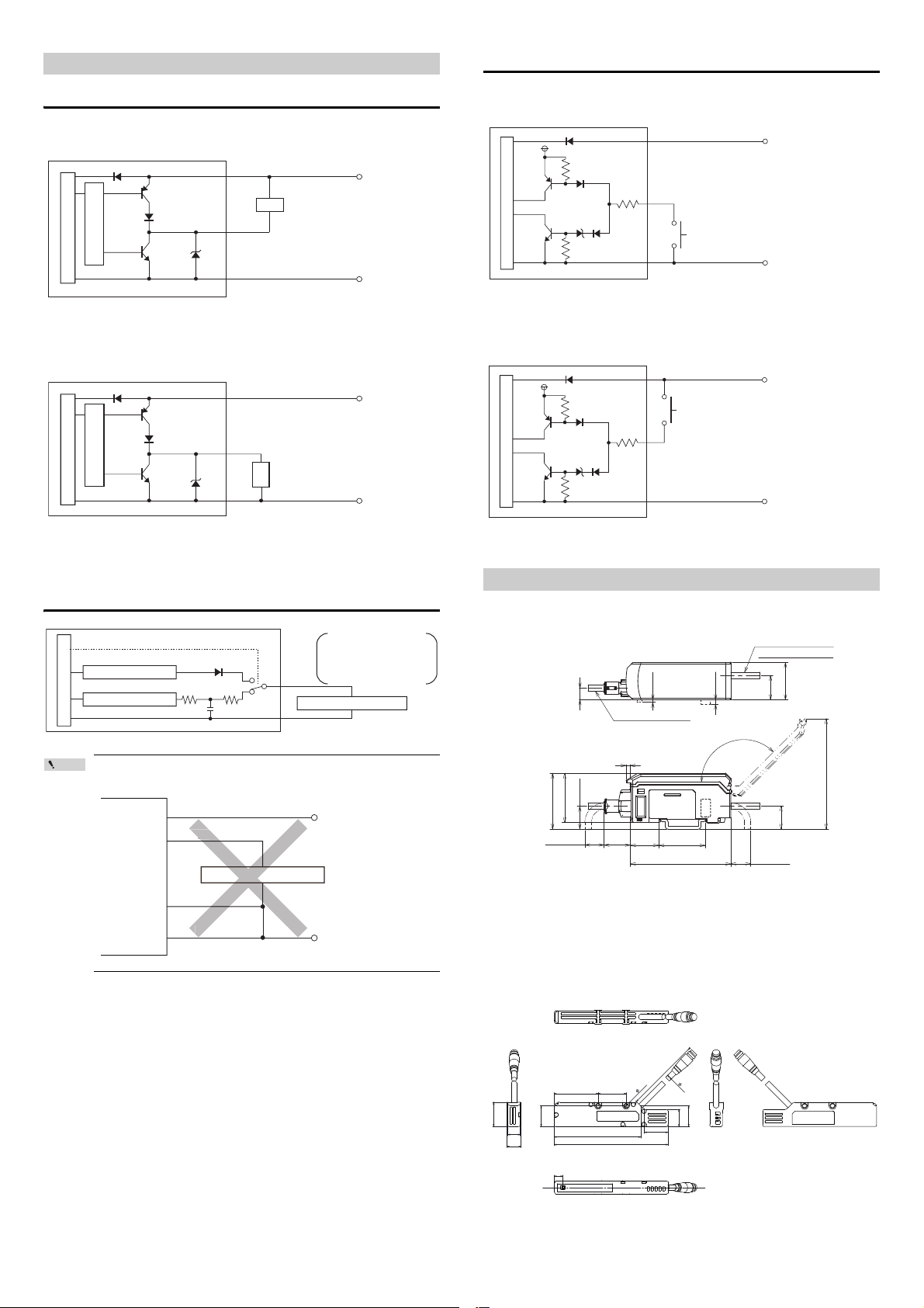
Circuit Diagram
Point
Main circuit
Overcurrent protection circuit
10 to 30 VDC
Brown
0 V
Blue
*
* Black (HI judgment output)/White (LO judgment output)/
Gray (GO judgment output)/Green (alarm output)
Load
10 to 30 VDC
Brown
*
0 V
Blue
* Black (HI judgment output)/White (LO judgment output)/
Gray (GO judgment output)/Green (edge check output)
Main circuit
Load
Overcurrent protection circuit
e
42.4
37.4
17.4
20 21.6
(Min. 15)
(Min. 15)
35.4
76.3
17.6
8.9
When the cover is open: Max. 109.2
Max.135°
3
Cable diameter:
ø
4.7
Cable length: 2 m
*1
28.3
18.5
(1.9)
*2
(3.4)
*2
Cable diameter: ø4.8
Input Circuit Diagram
Output Circuit Diagram
When NPN output is selected
When PNP output is selected
When NPN output is selected
+5V
Main circuit
(Short-circuit current 2 mA or less)
Brown
*
Blue
* Pink (External input 1)/Yellow (External input 2)/
Pink and Purple(External input 3)/Purple (External input 4)
When PNP output is selected
Brown
Main circuit
(Short-circuit current 2 mA or less)
*
Blue
* Pink (External input 1)/Yellow (External input 2)/
Pink and Purple(External input 3)/Purple (External input 4)
10 to 30 VDC
0 V
10 to 30 VDC
0 V
Analog Output Circuit
(Switching signal)
Analog current output circuit
Analog voltage output circuit
Main circuit
Do not short-circuit the shield (analog output GND) and
blue (0 V).
Brown
Orange
Analog input equipment
Shield
Blue
Analog voltage/current
output circuit
0 to 5 V, 1 to 5 V, -5 to 5 V,
Orange
4 to 20 mA
Analog input equipment
Shield (Analog output GND)
10 to 30 VDC
0 V
Dimensions
z Amplifier
SK-1000/SK-1050
*1 Cable specification : SK-1000 12 cores, Nominal cross-section area
brown/blue: 0.20 mm
: SK-1050 8 cores, Nominal cross-section area:
0.15 mm
2
*2 Not mounted on the SK-1000.
z Sensor Head
SK-050
2
, others 0.15 mm
2
E SK-1000 IM
18
Page 19

SK-050+OP-87934
OP-87934
Response Time
Response Time
The response time is the time from the point when the sensor recognizes a change
in the electric potential of the target to the point when output is generated.
Judgment output response time (maximum value)
Averaging rate Response time (ms)
15
27
410
816
16 28
64 102
256 397
1024 1580
4096 6310
16384 25232
Analog output response time=
Judgment output response time + 0.3 ms
6. Appendix
Troubleshooting
This section describes corrective actions when errors occur.
Frequently Asked Questions
Problem Check points Corrective actions
Nothing is
displayed on the
amplifier control
unit.
The value
fluctuates.
Button operations
are ignored.
The judgment
output is not output
properly.
The analog output
cannot be output
properly.
The bank cannot
be switched by the
external input
The sensor head
indicator does not
change.
Is the power cable connected
correctly?
Is the sensor amplifier
correctly connected?
Is the averaging value too
small (response time set too
fast)?
Is the object or sensor head
vibrating?
Has the mounting position
changed?
Are the output wires and input
wires short-circuited?
Is the key lock function
enabled?
Is the output polarity set
correctly?
Is the unit properly wired?
Is the tolerance setting value
set correctly?
Is the output state (N.O./N.C.)
set correctly?
Is the unit properly wired?
Is the type of analog output
(current/voltage) set
correctly?
Is the bank switching method
set correctly?
Is the supplied voltage within
the specification range?
Is there an error message on
the sensor amplifier?
Connect the power cable correctly.
"Mounting and Wiring the Sensor
Amplifier" (page 4)
Connect the sensor amplifier correctly.
"Mounting the Sensor Amplifier"
(page 4)
Increase the averaging.
"2. Averaging rate" (page 11)
Take adequate measures to prevent
vibration.
Correctly mount the sensor head.
"Mounting the Sensor Head" (page 5)
Check the wiring.
"Mounting and Wiring the Sensor
Amplifier" (page 4)
Cancel the key lock function.
"Key Lock Function" (page 10)
The connected communication unit <DLRS1A> read/write setting switch is set to
RW.
Set the read/write setting switch to R.
"RS-232C Communication Unit DLRS1A User's Manual"
Change the settings for NPN output and
PNP output.
"Initial Reset (Initialize)" (page 8)
Wire the unit correctly.
"Output Circuit Diagram" (page 18)
Set the tolerance setting value.
"Changing the Tolerance Values"
(page 9)
Set the output state.
"3. Output state" (page 11)
Wire the unit correctly.
"Output Circuit Diagram" (page 18)
Select the correct type of analog output.
"Initial Reset (Initialize)" (page 8)
Set the bank switching method.
"11. Bank switching method" (page
16)
Use power voltage within the
specification range.
"5. Specifications" (page 17)
Take adequate measures according to
the error messages.
"Error Displays and Corrective
Actions" (page 20)
19
E SK-1000 IM
Page 20
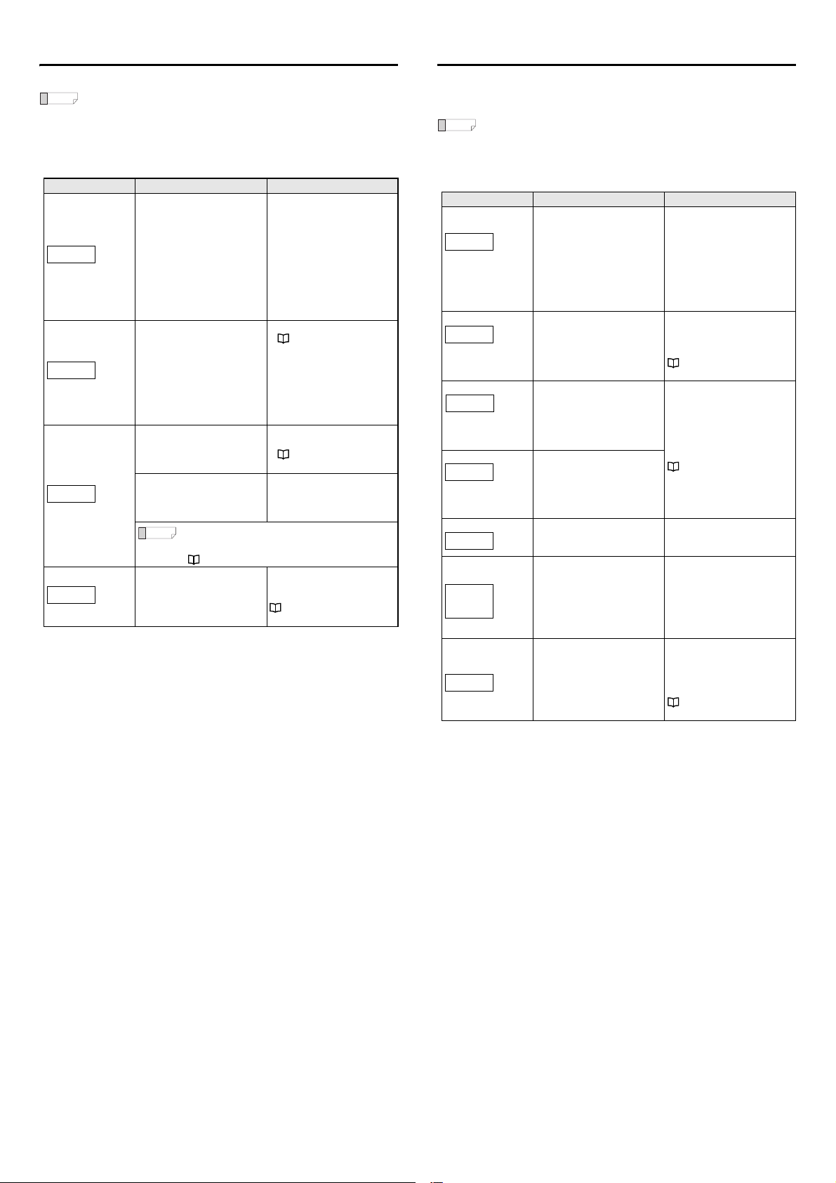
Error Displays and Corrective Actions
Reference
Reference
ErH
ErC
ErE
Er.coM
-----
-----
-FFFF
FFFF
bK.Loc
Err
ShiFt
cMLoc
Non-Error Displays and Corrective Actions
When an error occurs, an error message appears on the sensor amplifier.
• If an error occurs, the judgment output changes to the error status
and the alarm output turns OFF.
• When [ErC] is displayed, all judgment outputs and alarm outputs
turn OFF to protect the outputs.
• When the error display is other than [ErC] or [ErE], the analog
voltage output is 5.5 V and the analog output current is 3.0 mA.
Error displays Error contents Corrective actions
• Check the sensor head
connection.
• Check whether the head cable
is damaged.
• Check the connection of the
head cable to the connector.
• After checking the previous
items, cycle power.
• Check the models of the
sensor head and sensor
amplifier for compatibility.
• Wire the unit correctly.
"Output Circuit Diagram"
(page 18)
• Check the load and reduce the
current to be within th e
specification range.
• Check that the output wire is
not touching other wires or
ground.
• Cycle power.
• Perform the initial reset.
"Initial Reset (Initialize)"
(page 8)
To save the setting values when
the power is turned OFF, replace
the sensor amplifier.
Change the settings on the
expansion amplifiers again after
cycling power.
"Mounting the Sensor
Amplifier" (page 4)
Head error
Overcurrent error
EEPROM error
Communication error
• The sensor head is not
connected.
• The head cable is damaged.
• The sensor head is damaged.
• A sensor head is connected
that is incompatible with this
amplifier.
Overcurrent beyond specification
is flowing through the judgment
output or alarm output.
Reading/writing the nonvolatile
memory (EEPROM) storage has
failed.
Data has been written in the
nonvolatile memory (EEPROM)
over 1 million times and
malfunction occurred.
When using the zero shift function frequently, make
sure that the zero shift value is not saved in the
nonvolatile memory (EEPROM).
" 12. Zero shift value memory function" (page 16)
Communication cannot be
established with the expansion
sensor amplifiers.
When the judgment value (P.V.) is "-----" the judgment outputs turn OFF (When
Normally Open is set), the analog voltage output is 5.5 V and the analog output
current is 3.0 mA.
If the internal measurement value (R.V.) becomes [-----] because the
Reference
target is out of the measurement range, the internal measurement
value (R.V.) retains the value immediately before the target disappears
for the period the response time elapses. After the response time
elapses, the internal measurement value (R.V.) becomes [-----].
Display Description Corrective actions
This occurs when the power is
turned on and immediately after
the head is connected or a reset
is performed. When the amount
of processing specified by the
set averaging rate finishes and
the measured value is confirmed,
this value will be shown on the
measured value display.
Check the hold function setting.
Input the timing input according
to the setting.
" 6. Hold Function" (page 12)
Check the set measurement
range, and if necessary, set it to a
range that corresponds to the
charged state of the target.
" 1. Measurement range"
(page 11)
To switch the banks with button
operations, set "11. Bank
switching method" to btn.
Shift the display with the internal
measurement value (R.V.) in the
numeric state (the state in which
the target is measured).
The connected communication
unit <DL-RS1A> read/write
setting switch is set to RW.
Set the read/write setting switch
to R.
"RS-232C Communication
Unit DL-RS1A User's Manual"
The internal
measurement value
(R.V.) is displayed as
[-----].
The judgment value
(P.V.) is displayed as
[-----].
The measurement
value is displayed as
[-ffff].
The measurement
value is displayed as
[ffff].
The averaging buffer is not full
and the measured value has not
been confirmed.
The hold function is used and the
judgment value (P.V.) has not
been confirmed.
The measurement value is
smaller than the lower limit of the
display range.
The measurement value is larger
than the upper limit of the display
range.
The bank switching method is set
to external input.
When R.V. is [-----], [FFFF], or
[-FFFF] - that is, when the value is
too large (a value outside of ±500
V in near mode and a value
outside of ±12.5 kV in far mode)the zero shift function has been
used.
The button operation is disabled.
E SK-1000 IM
20
Page 21

Display Screen and Output
Reference
-----
FFFF
-FFFF
ErC
ErE
Normally, the judgment value (P.V.) is displayed on the main display (upper level).
This section describes the judgment output and analog output status when
displays other than numbers appear on the main display.
The judgment indicator on the sensor amplifier operates in the same
way as Normally Open regardless of the output state setting.
Analog
output
Vol ta ge
(current)
value
Voltage
(current) for
measured
value
Analog
voltage
output: 5.5 V
fixed
Analog current
output: 3.0 mA
fixed
Upper limit of
analog output
range (For 1-5
V, fixed to 5 V)
(When upper
limit < lower
limit: 1 V)
Lower limit of
analog output
range (For 1-5
V, fixed to 1 V)
(When upper
limit < lower
limit: 5 V)
Follows
setting details
Analog
voltage
output: 5.5 V
fixed
Analog current
output: 3.0 mA
fixed
Voltage
(current) for
measured
value
Voltage
(current) for
measured
value
Status
Measuring
Out of
measurement
range
Out of display
range
Out of display
range
Setting
Other than [Erc],
[ErE] errors
" Error
Displays and
Corrective
Actions" (page
20)
Overcurrent error
EEPROM error
Amplifier Control input Control output
Upper
Judgment
level
indicator
main
display
Judgment
Measure-
value
ment
(P.V)
results
----- All off Yes Yes No All OFF
Only HI
FFFF
lights
Only LO
-FFFF
lights
Follows
Setting
setting
item
details
HI/LO
Error
simulta-
display
neously
light
ErC All off Yes Yes Yes All OFF
Measurement
ErE
results
Bank
Timing/
switching/
Reset
emission
stop
Yes Yes Ye s
Yes Yes N o
Yes Yes N o
During
error:
No
Other
Yes
than
error:
Yes
No Yes No
Yes Yes Ye s
Zero-shift
Outside
measurement
range,
during
error: No
Judgment
output
Measurement
results
Only HI
output ON
Only LO
output ON
Follows
setting
details
HI/LO
output
simultaneously ON
Measurement
results
Alarm
Output:
ON
Display:
OFF
Output:
OFF
Display:
ON
Output:
ON
Display:
OFF
Output:
ON
Display:
OFF
Output:
ON
Display:
OFF
Output:
OFF
Display:
ON
Measurement in
progress,
or same as
out of measurement
range
Measurement in
progress,
or same as
out of measurement
range
Factory Setting (Default Value) List
This section describes the factory settings (default values).
If the initial reset is performed, the following default values will be restored.
" Initial Reset (Initialize)" (page 8)
Values set on the main screen
Banks 0 to 3 will all be set to the same values.
Setting item Default value
HI tolerance setting value 1.000
LO tolerance setting value -1.000
Basic settings and advanced settings
Setting item
1. Measurement range
2. Averaging rate
3. Output state
4. Distance setting
5. Area scaling
6. Hold function
7. Timing input
8. Hysteresis
9. Analog output scaling
10. External input
11. Bank switching method
12. Zero shift value memory
function
13. Display digit
Default
value
Measurement can be performed in the range of 0
near
to ±2 kV and the reference distance for
measurement is 25 mm.
64
Averaging rate: 64
no
Normally open
dEFLt
The distance will not be corrected.
1.00
1.00
S-H
Sample hold.
LEvEL
Level
0.100
0.100
dEFLt
Default setting
dEFLt
Default setting
btn
Button operation
Data will not be stored in the nonvolatile memory
M-oFF
(EEPROM).
dEFLt
Default setting
Description
21
E SK-1000 IM
Page 22

WARRANTIES AND DISCLAIMERS
(1) KEYENCE warrants the Products to be free of defects in materials and
workmanship for a period of one (1) year from the date of shipment. If any
models or samples were shown to Buyer, such models or samples were used
merely to illustrate the general type and quality of the Products and not to
represent that the Products would necessarily conform to said models or
samples. Any Products found to be defective must be shipped to KEYENCE
with all shipping costs paid by Buyer or offered to KEYENCE for inspection and
examination. Upon examination by KEYENCE, KEYENCE, at its sole option,
will refund the purchase price of, or repair or replace at no charge any Products
found to be defective. This warranty does not apply to any defects resulting
from any action of Buyer, including but not limited to improper installation,
improper interfacing, improper repair, unauthorized modification, misapplication
and mishandling, such as exposure to excessive current, heat, coldness,
moisture, vibration or outdoors air. Components which wear are not warranted.
(2) KEYENCE is pleased to offer suggestions on the use of its various Products.
They are only suggestions, and it is Buyer's responsibility to ascertain the
fitness of the Products for Buyer’s intended use. KEYENCE will not be
responsible for any damages that may result from the use of the Products.
(3) The Products and any samples ("Products/Samples") supplied to Buyer are not
to be used internally in humans, for human transpor tation, as safety devices or
fail-safe systems, unless their written specifications state otherwise. Should any
Products/Samples be used in such a manner or misused in any way,
KEYENCE assumes no responsibility, and additionally Buyer will indemnify
KEYENCE and hold KEYENCE harmless from any liability or damage
whatsoever arising out of any misuse of the Products/Samples.
(4) OTHER THAN AS STATED HEREIN, THE PRODUCTS/SAMPLES ARE
PROVIDED WITH NO OTHER WARRANTIES WHATSOEVER. ALL
EXPRESS, IMPLIED, AND STATUTORY WARRANTIES, INCLUDING,
WITHOUT LIMITATION, THE WARRANTIES OF MERCHANTABILITY,
FITNESS FOR A PARTICULAR PURPOSE, AND NON-INFRINGEMENT OF
PROPRIETARY RIGHTS, ARE EXPRESSLY DISCLAIMED.
IN NO EVENT SHALL KEYENCE AND ITS AFFILIATED ENTITIES BE
LIABLE TO ANY PERSON OR ENTITY FOR ANY DIRECT, INDIRECT,
INCIDENTAL, PUNITIVE, SPECIAL OR CONSEQUENTIAL DAMAGES
(INCLUDING, WITHOUT LIMITATION, ANY DAMAGES RESULTING FROM
LOSS OF USE, BUSINESS INTERRUPTION, LOSS OF INFORMATION,
LOSS OR INACCURACY OF DATA, LOSS OF PROFITS, LOSS OF
SAVINGS, THE COST OF PROCUREMENT OF SUBSTITUTED GOODS,
SERVICES OR TECHNOLOGIES, OR FOR ANY MATTER ARISING OUT OF
OR IN CONNECTION WITH THE USE OR INABILITY TO USE THE
PRODUCTS, EVEN IF KEYENCE OR ONE OF ITS AFFILIATED ENTITIES
WAS ADVISED OF A POSSIBLE THIRD PARTY’S CLAIM FOR DAMAGES
OR ANY OTHER CLAIM AGAINST BUYER. In some jurisdictions, some of the
foregoing warranty disclaimers or damage limitations may not apply.
BUYER'S TRANSFER OBLIGATIONS:
If the Products/Samples purchased by Buyer are to be resold or delivered to a
third party, Buyer must provide such third party with a copy of this document, all
specifications, manuals, catalogs, leaflets and written information provided to
Buyer pertaining to the Products/Samples.
E 1101-3
E SK-1000 IM
22
Page 23

23
E SK-1000 IM
Page 24

Copyright (c) 2014 KEYENCE CORPORATION. All rights reserved.
13427E 1114-1 96M13428 Printed in Japan
E SK-1000 IM
24
 Loading...