


1 |
Setting up your |
Kenwood |
|
Audio System |
Spectrum 350

Licensing
Manufactured under license from Dolby Laboratories Licensing Corporation. Additionally licensed under one or more of the following patents: US numbers 3,632,886; 3,746,792; and 3,959,590; Canadian numbers 1,004,603 and 1,037,877. ‘Dolby’, and the ) symbol are trademarks of Dolby Laboratories Licensing Corporation.
2.
Safety first
WARNING:
TO PREVENT FIRE OR ELECTRIC SHOCK, DO NOT
EXPOSE THIS UNIT TO RAIN OR MOISTURE.
Safety Symbols
We’ve placed these safety symbols on the back of the unit.
CAUTION |
! |
RISK OF ELECTRIC SHOCK |
|
DO NOT OPEN |
|
|
|
CAUTION:
To prevent electric shock, match the wide blade of the plug to the wide slot in a wall socket, and insert fully.
The lightning bolt symbol is to alert you to the danger of electric shock from the operating of electric parts inside the unit.
!The exclamation point symbol is to let you know that there are important operating and servicing instructions in this
manual that you should read before you operate this unit.
Canadian IC Compliance Notice
This device complies with RSS-210 of Industry Canada. Operation is subject to the following two conditions: (1) this device may not cause interference, and (2) this device must accept any interference, including interference that may cause undesired operation of the device.
Rechargeable Battery Warning
If this unit uses a rechargeable battery, use the battery charger that came with the unit only. Do NOT take apart, damage, burn, or short circuit the battery, or expose it to heat—this could cause it to burst or to release toxic materials. Keep the battery away from children.
About the power supply
This unit is designed for operation in the USA and Canada using a power supply of AC 120 volts only.
Safety Precautions
Read this page carefully to ensure safe operation.
Please read all of the safety and operating instructions before operating this unit. Adhere to all warnings on the unit and in this manual. Follow all the safety and operating instructions. These safety and operating instructions should be retained for future reference.
1Power sources. The unit should be connected to a power supply only of the type described in this manual or as marked on the unit. If you are not sure of the type of power supply to your home, consult your unit dealer or local power company. For units intended to operate from battery power, or other sources, refer to the instruction manual.
2Power-cord protection. Power supply cords should be routed so that they are not likely to be walked on or pinched by items placed upon or against them, paying particular attention to cords at plugs, convenience receptacles, and the point where they exit from the unit.
3CAUTION—Polarization. This unit may be equipped with a polarized alter- nating-current line plug (a plug having one blade wider that the other). This plug will fit into the power outlet only one way. This is a safety feature. If you are unable to insert the plug fully into the outlet, try reversing the plug. If the plug should still fail to fit, contact your electrician to replace your outlet. Do not defeat the safety purpose of the polarized plug.
4Ventilation. Slots and openings in the cabinet are provided for ventilation and to ensure reliable operation of the unit and to protect it from overheating, and these openings must not be blocked or covered. The unit should be situated so that its location or position does not interfere with its proper ventilation.
To maintain good ventilation, do not put records or a table-cloth on the unit. Place the unit at least 4 inches away from the walls.
3.
Do not use the unit on a bed, sofa, rug or similar surface that may block the ventilation openings. This unit should not be placed in a built-in installation such as a bookcase or rack unless proper ventilation is provided or the manufacturer’s instructions have been adhered to.
5Water and moisture. The unit should not be used near water. for example, near a bathtub, washbowl, kitchen sink, laundry tub, in a wet basement, or near a swimming pool, etc.
6Temperature. The unit may not function properly if used at extremely low, or freezing temperatures. The ideal ambient temperature is above +41ºF.
7Heat. The unit should be situated away from heat sources such as radiators, heat registers, stoves, or other units (including amplifiers) that produce heat.
8Electric Shock. Care should be taken so that objects do not fall and liquid is not spilled into the enclosure through openings. If a metal object, such as a hair pin or a needle, comes into contact with the inside of this unit, a dangerous electric shock may result. For families with children, never permit children to put anything, especially metal, inside this unit.
9Enclosure removal. Never remove the enclosure. If the internal parts are touched accidentally, a serious electric shock might occur.
10Cleaning. Unplug this unit from the wall outlet before cleaning. Do not use volatile solvents such as alcohol, paint thinner, gasoline, or benzine, etc. to clean the cabinet. Use a clean dry cloth.
11Lightning. For added protection for this unit during a lightning storm, or when it is left unattended and unused for long periods of time, unplug it from the wall outlet and disconnect the antenna or cable system. This will prevent damage to the unit due to lightning and power-line surges.
12Abnormal smell. If an abnormal smell or smoke is detected, immediately turn the power OFF and unplug the unit from the wall outlet. Contact your dealer or nearest service center.
13Damage requiring service. The unit should be serviced by qualified service personnel when:
The power-supply cord or the plug has been damaged.
Objects have fallen, or liquid has been spilled into the unit.
The unit has been exposed to rain or water.
The unit has been dropped, or the enclosure damaged.
The unit exhibits a marked change in performance.
The unit does not appear to operate normally by following the instruction manual. Adjust only those controls that are covered by the instruction manual as an improper adjustment of other controls may result in damage and will often require extensive work by a qualified technician to restore the unit to its normal operation.
14Servicing. The user should not attempt to service the unit beyond that described in the instruction manual. All other servicing should be referred to qualified service personnel.
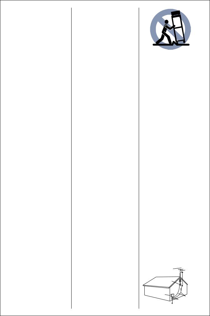
15Power lines. An outside antenna system should not be located in the vicinity of overhead power lines or other electric light or power circuits, or where it can fall into such power lines or circuits. When installing an outside antenna system, extreme care should be taken to keep from touching such power lines or circuits as contact with them might be fatal.
16AC outlets. Do not connect other audio equipment with a power consumption larger than that specified to the AC outlet on the rear panel. Never connect other electrical units, such as an iron or toaster, to it to prevent fire or electric shock.
17Overloading. Do not overload wall outlets, extension cords, or integral convenience receptacles as this can result in a risk of fire or electric shock.
18Attachment. Do not use attachments not recommended by the unit manufacturer as they may cause hazards.
19Replacement parts. When replacement parts are required, be sure the service technician has used replacement parts specified by the manufacturer or have the same characteristics as the original parts. Unauthorized substitutions may result in fire, electric shock, or other hazards.
20Safety check. Upon completion of any service or repairs to this unit, ask the service technician to perform safety checks to determine that the unit is in proper operating condition.
21Carts and stands. Don’t put this unit on a cart or stand that is unsteady or that can not support the unit’s weight. If you move this unit on a cart or stand, be careful—quick stops, excessive force and pushing over or uneven surfaces, may cause the cart to overturn and damage your equipment.
FCC Warning
This equipment may generate or use radio frequency energy. Changes or modifications to this equipment may cause harmful interference unless the modifications are expressly approved in the instruction manual. The user could lose the authority to operate this equipment if an unauthorized change or modification is made.
Important
This equipment has been tested and found to comply with the limits for a Class B digital device, pursuant to Part 15 of the FCC Rules.
These limits are designed to provide reasonable protection against harmful interference in a residential installation. This equipment may cause harmful interference to radio communications if it is not installed and used in accordance with the instructions. However, there is no guarantee that interference will not occur in a particular installation. If this equipment does cause harmful interference to radio or television reception, which can be determined by turning the equipment OFF and ON, the user is encouraged to try to correct the interference by one or more of the following measures:
•Reorient or relocate the receiving antenna
•Increase the separation between the equipment and receiver
•Connect the equipment into an outlet on a circuit different from that to which the receiver is connected
•Consult the dealer or an experienced radio/TV technician for help
Cable System Installer Notice
Article 820-40 of the NEC provides guidelines for proper grounding and, in particular, specifies that the cable ground shall be connected to the grounding system of the building, as close to the point of cable entry as practical.
 Antenna
lead in wire
Grounding clamp
 Antenna discharge unit
(NEC section 810-20)
Electrical service equipment
Grounding conductors (NEC section 810-21)
Grounding clamps
 Power service grounding Electrode system
(NEC ART 250, part H)
4.

Contents
Safety First . . . . . . . . . . . . . . . . . . . . . . . . . . . . . . . . . . 3
Welcome . . . . . . . . . . . . . . . . . . . . . . . . . . . . . . . . . . . . . 6
Unpacking . . . . . . . . . . . . . . . . . . . . . . . . . . . . . . . . . 6
Did you get everything?. . . . . . . . . . . . . . . . . . . . 6
You may need to purchase. . . . . . . . . . . . . . . . . 6
You’ll need these tools. . . . . . . . . . . . . . . . . . . . . 6
Assembling the rack . . . . . . . . . . . . . . . . . . . . . . . 7
How to get replacement parts
for your rack . . . . . . . . . . . . . . . . . . . . . . . . . . . . . 10
Placing your system . . . . . . . . . . . . . . . . . . . . . . 11
Stacking your components in the rack . . . . 11
Positioning your speakers. . . . . . . . . . . . . . . . . 11
Connecting your components . . . . . . . . . . . 12
Connecting your speakers . . . . . . . . . . . . . . . . 12
Connecting your CD player, cassette deck, and optional turntable or VCR. . . . . . . . . . . . 13
Connecting your antennas . . . . . . . . . . . . . . . . 14
Connecting the antenna wires to the
antenna jacks . . . . . . . . . . . . . . . . . . . . . . . . . . . . . . . 14 Using the AM indoor loop antenna (supplied) . . . 14 Using the FM indoor antenna (supplied) . . . . . . . . 14 Using an AM outdoor antenna (optional) . . . . . . . 15 Using a FM outdoor antenna (optional) . . . . . . . . . 15
Connecting the system control cables . . . . 16
Connecting other audio components . . . . . 17
Plugging in your power cords. . . . . . . . . . . 18
Turning on the power . . . . . . . . . . . . . . . . . . . . 19
Warranty . . . . . . . . . . . . . . . . . . . . . . . . . . . . . . . . . . . 21
5.

Welcome
Setting up your SPECTRUM System isn’t difficult, but getting your system up and running will be even easier if you follow the step-by-step directions in this manual.
Unpacking
Unpack all of the components carefully, and examine them for shipping damage. If any are damaged or fail to operate, notify your dealer immediately. If your SPECTRUM System was shipped to you directly, notify the shipping company without delay. Only the person or company who originally received the system can file a claim against the carrier for shipping damage. Keep the original carton and packing materials in case you need to transport or ship your SPECTRUM System.
Did you get everything?
Check the lists below to make sure you have everything. And before you start setting up the system, look at the list of tools and other items you need. If you’re setting up other components along with your system, read the manual that came with each of those components to see what you need.
Receiver parts
•Receiver (KR-596)
•Remote Control (RC-S0501)
•2 Batteries for remote
•FM indoor antenna
•AM loop antenna
•Loop antenna stand
CD player parts
•CD Player (DP-R896)
•Audio cable
•System control cable
Cassette deck parts
•Cassette Deck (KX-W595)
•2 Audio cables
Speaker parts
•2 Main speakers (JL-506)
•2 Speaker wires
Rack parts
•Left panel
•Right panel
•Rack base
•RAck top
•Top back panel
•Bottom back panel
•Kick panel
•Fixed shelf
•Removable shelf
•Glass Door
•Hardware bag
(see page 7 for contents of the hardware bag)
You may need to purchase
•Audio cables
•Video cables
•Speaker wire
You’ll need these tools
•Screwdriver (slot and/or Phillips)
•Pliers
6.
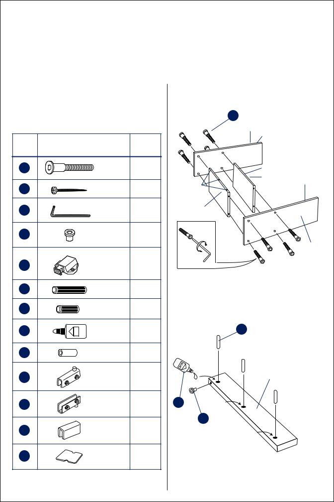
Assembling the rack
Hardware list
Before assembling your rack check to be sure that you received all of the hardware listed below.
Item |
Description |
Quantity |
|
J |
Allen bolt |
8 |
|
K |
Phillips head |
12 |
|
|
screw |
|
|
L |
Allen wrench |
1 |
|
M |
Hinge insert |
2 |
|
N |
Magnetic |
1 |
|
catch |
|||
O |
Wood dowel |
2 |
|
(long) |
|||
|
|
||
|
Wood dowel |
9 |
|
|
(short) |
|
|
R |
Glue |
1 |
|
|
Shelf pin |
4 |
|
T |
Upper hinge |
1 |
|
U |
Lower hinge |
1 |
|
V |
Catch plate |
1 |
|
W |
Catch plate |
1 |
|
pad |
|||
|
|
Step1
J x 8
Left side
Finished edge
|
Finished edge |
Dowel holes |
Fixed shelf |
Finished edge |
|
for kick panel |
|
Right side
Step 2
Q x 3
Kick Panel
R
M
7.
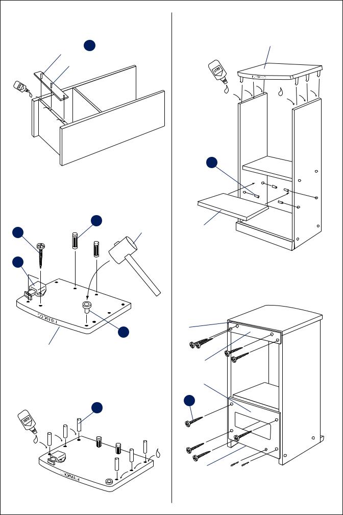
Step 3 |
|
Step 6 |
Hinge insert |
M faces |
Rack top |
toward top |
|
|
Kick Panel
Optional S x 4
Step 4
|
O x 2 |
Mallet |
|
|
|
K x 2 |
|
Removable |
|
(optional) |
|
|
|
N
Step 7
Top of panel should be 1/2" below top edge of rack
M
Rack top
Black surface of both
5 back panels face toward inside of rack
Step
K x 10
Q x 6
Bottom of panel 


 should be even with
bottom shelf
8.
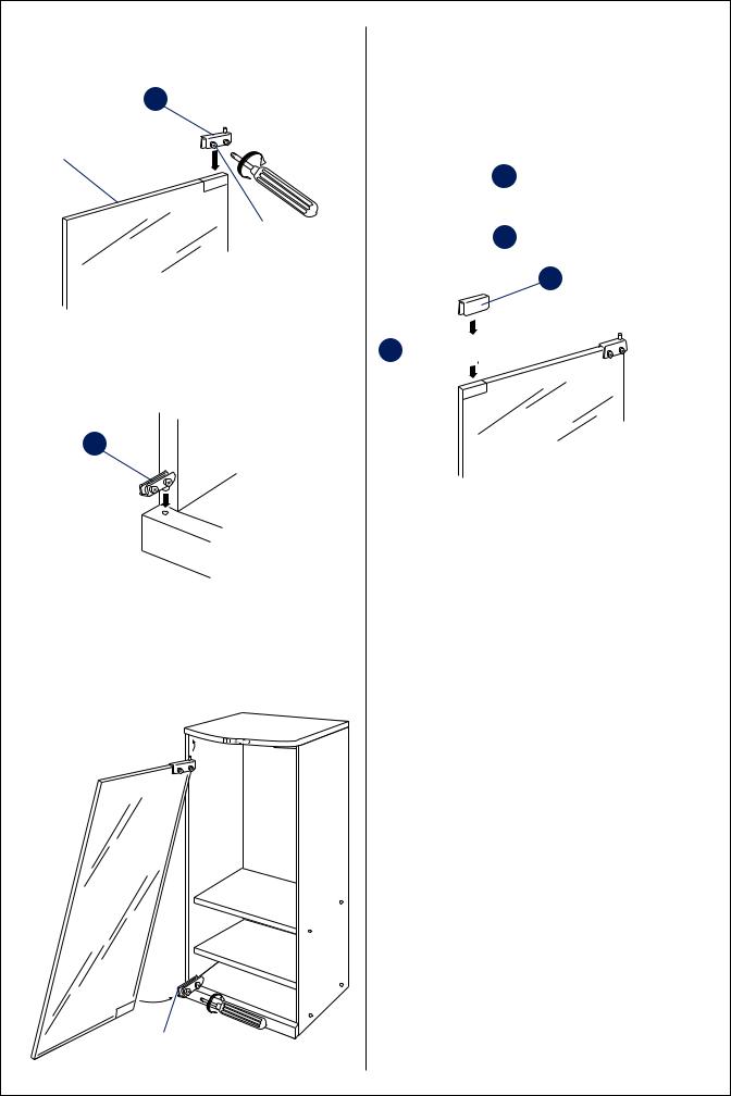
Step 8
T
Edge of hinge even  with edge of glass
Glass door
Screws face toward the inside of the rack
Step 9
U
Top edge of 
kick panel
Step 10
Slide door into hinge
(edge of hinge even with
edge of glass)
Step 11
First close the door to see where the magnetic catch contacts it.
Attach the cushion |
W |
the |
magnetic catch contacted it. |
|
|
Slip the catch plate |
V over the cushion. |
|
|
V |
|
W
9.

How to get replacement parts for your rack
If any of the rack parts are missing |
|
|
|
|
|
or damaged, look for the rack |
|
|
|
|
|
model number on the ID sticker on |
|
|
|
|
|
the back panel. Then, contact the |
|
|
|
|
|
appropriate company for replace- |
|
|
|
|
|
ment parts. |
|
|
|
|
|
If your rack’s model number is: |
Use the following parts list to identify missing or damaged parts: |
|
|||
SRC-406C |
|
|
|
SRC-406C |
SRC-406N |
|
Item |
Description |
Quantity |
Part No. |
Part No. |
contact: |
A |
Left side panel |
1 |
XW1061 |
349092-0 |
Tocabi America |
B |
Rack bottom |
1 |
XW0903 |
344739-1 |
755 Otay Valley Road |
C |
Right side panel |
1 |
XW1060 |
349093-9 |
Chula Vista, CA 91911 |
D |
Kick panel |
1 |
XW0902 |
344733-2 |
(619) 661-6136 |
E |
Rack top |
1 |
XW0897 |
344727-8 |
|
F |
Bottom back panel |
1 |
XW0905 |
433734-4 |
or |
G |
Fixed shelf |
1 |
XW0900 |
344737-5 |
|
H |
Removable shelf |
1 |
XW0901 |
344738-3 |
SRC-406N |
I |
Top back panel |
1 |
XW1062 |
431295-3 |
|
J |
Allen screws |
8 |
S0033 |
423699-8 |
contact: |
K |
Small screws |
12 |
S0034 |
414954-8 |
Kenwood |
L |
Allen wrench |
1 |
M0018 |
408737-2 |
1900 Gulf Street |
M |
Hinge inserts |
2 |
P0054 |
425226-8 |
Lamar MO 64759 |
N |
Magnetic door catch |
1 |
P0098 |
431264-3 |
(800) 327-9782 |
O |
Long wooden dowels |
2 |
W0981 |
429169-7 |
|
Q |
Short wooden dowels |
9 |
W0092 |
404578-5 |
|
R |
Glue |
1 |
G0012 |
404589-0 |
|
S |
Shelf pegs |
4 |
M0019 |
424881-3 |
|
T |
Top door hinge |
1 |
M0026 |
425226-8 |
|
U |
Bottom door hinge |
1 |
M0027 |
425226-8 |
|
V |
Door catch plate |
1 |
M0011 |
422201-6 |
|
W |
Catch plate pad |
1 |
G0047 |
422201-6 |
|
X |
Glass door |
1 |
G0241 |
431296-1 |
|
|
|
|
|
|
10.
Placing your system
Stacking your components in the rack
To make sure that they’re properly ventilated and stable, stack them according to the following diagram. If you’re using a turntable, place it on top of the rack.
|
AM-FM STEREO RECEIVER KR-596 |
|
|
|
|
|
|
|
|
|
|
|
BAND |
TUNING |
|||||
|
|
|
|
|
|
|
|
|
|
|
|
|
|
|
|
||||
|
|
|
|
|
|
|
|
|
|
|
|
AUTO/MANU. +10 |
|
|
|
|
|
||
|
|
|
|
|
|
|
|
|
|
|
|
MEMORY |
1 |
|
2 |
3 |
4 |
5 |
|
■ AUTO TUNING SYSTEM |
|
|
|
|
|
|
|
|
|
P.CALL |
6 |
|
7 |
8 |
9 |
0 |
|||
■ 30 STATION RANDOM PRESET |
|
|
|
|
|
|
|
|
|
|
|
|
|
|
|
|
|||
|
|
|
|
|
|
|
|
|
|
|
|
|
|
|
|
VOLUME CONTROL |
|||
|
|
|
|
|
|
|
|
|
|
|
|
|
|
|
|
DOWN |
UP |
||
BASS |
|
TREBLE |
|
STANDBY |
|
|
|
|
SPEAKERS |
INPUT SELECTOR |
|
|
|
|
|
||||
2 FLAT 2 |
|
2 FLAT 2 |
|
|
|
|
|
|
|
|
|
|
|
||||||
|
|
|
|
|
|
|
|
|
|
|
|
|
|
|
|
||||
4 |
4 |
|
4 |
4 |
|
|
|
|
|
|
|
|
|
|
|
|
|
|
|
6 |
6 |
6 |
6 |
|
|
|
|
|
|
|
|
|
|
|
|
|
|
||
8 |
8 |
|
8 |
8 |
|
|
|
|
|
|
|
|
|
|
|
|
|
|
|
-10 |
+10 |
|
-10 |
+10 |
|
|
|
|
|
|
SPEAKERS |
|
|
|
|
|
|
|
|
|
|
|
|
|
|
|
|
|
|
|
|
|
|
|
|
|
|
|
|
POWER |
PHONES |
|
|
|
|
|
|
|
|
|
|
|
|
|
L |
BALANCE |
R |
||
|
|
|
|
|
|
|
|
|
|
|
|
|
|
||||||
ON/STANDBY |
|
|
|
|
|
|
|
|
|
|
|
|
|
|
|
|
|
|
|
|
|
|
|
|
|
|
|
|
|
|
|
|
|
|
|
|
|
)VWX |
|
STEREO DOUBLE CASSETTE DECK KX-W595 |
|
|
|
|
|
|
|
|
|
|
|
|
|
|
|
|
|||
|
|
|
|
|
|
|
|
|
|
|
REC |
|
|
|
|
|
|
|
|
|
|
|
|
|
|
|
|
|
|
|
DUBBING |
|
|
|
|
|
|
|
|
|
|
|
|
|
|
ON |
OFF |
ON |
OFF |
HIGH |
NORMAL |
|
|
|
|
|
|
|
|
|
|
|
|
|
|
DOLBY NR |
DUBBING |
TAPE SELECTOR |
|
|
|
|
|
|
|
|
|||
|
|
PLAYBACK ONLY |
|
A |
|
|
|
|
|
|
B |
|
RECORDING/PLAYBACK |
|
|
|
|||
|
PLAY |
REW |
FF |
STOP/EJECT |
PAUSE |
POWER |
|
|
REC LEVEL |
REC |
PLAY |
REW |
FF |
STOP/EJECT |
PAUSE |
|
|||
|
|
|
|
/ |
II |
|
|
|
|
|
|
|
|
|
|
|
/ |
II |
|
|
|
|
|
|
|
ON |
STANDBY |
|
|
|
|
|
|
|
|
|
|
|
|
|
|
|
EDIT |
|
|
|
|
|
|
|
|
|
|
|
|
|
OPEN/CLOSE |
||
|
|
|
MODE |
|
|
|
|
|
|
|
|
|
|
|
DISC SKIP |
||||
MULTIPLE COMPACT DISC PLAYER DP-R896 |
|
|
|
|
|
|
|
|
|
|
|
|
|
|
|
|
|
||
POWER |
|
|
P.MODE |
CHECK |
CLEAR |
|
|
|
|
|
|
DISC 1 |
DISC 2 |
DISC 3 |
DISC 4 |
DISC 5 |
|
STOP |
|
|
|
|
TIME DSP |
RANDOM |
REPEAT |
|
|
|
|
|
|
|
|
|
|
|
|
|
|
ON |
STANDBY |
|
|
|
|
|
|
|
|
|
|
|
|
|
|
|
|
|
|
|
|
|
|
|
|
|
|
|
|
|
|
|
|
|
|
|
|
PLAY/PAUSE |
|
|
|
|
|
|
|
|
|
|
|
|
|
|
|
|
|
|
|
/II |
|
|
|
|
|
|
|
|
|
|
|
Receiver (KR-596) |
|
||||||||
|
|
|
|
|
|
|
|
Cassette |
|
(KX-W595) |
|||||||||
|
|
|
|
|
|
CD Player (DP-R896) |
|
|
|
|
|
||||||||
Positioning your speakers
You can get the best stereo effect by placing your speakers 6' to 12' apart along the same wall, with the main listening area midway between the 2 speakers.
•To enhance the stereo effect (especially if the speakers are more than 8' apart), rotate each speaker slightly toward the listening area.
•Placing the speakers against a wall will increase their bass output, but could also make them sound unnaturally ‘thick’ or ‘heavy’. If this occurs, try moving them away from the wall a foot or so.
11.
Connecting your components
Important:
Please wait until you’ve connected all of the cables before plugging any of the components into AC wall outlets and turning them on.
Connecting your speakers
Connect your speakers first. You’ll have an easier time getting to the connections on the backs of the components before you connect all of the other cables.
1Place the speakers in their approximate locations first, then leave a little extra speaker wire so you can fine-tune their locations.
2Use the speaker wire supplied with the speakers. If you need longer wire, buy speaker wire that is 18-gauge or thicker.
Remember, the smaller the number, the thicker the wire: 18-gauge wire is thicker than 20-gauge.
A few tips
•To save you time, we’ve removed the insulation from the ends of the speaker wire we supplied.
•When connecting speaker wires, be sure to connect positive connections to each other and negative connections to each other. Connecting positive to negative (+ to - ) or negative to
positive (- to +) can cause poor sound quality.
•Never allow the positive and negative speaker wires to touch each other. Touching wires can cause a short circuit, which could damage your electronics.
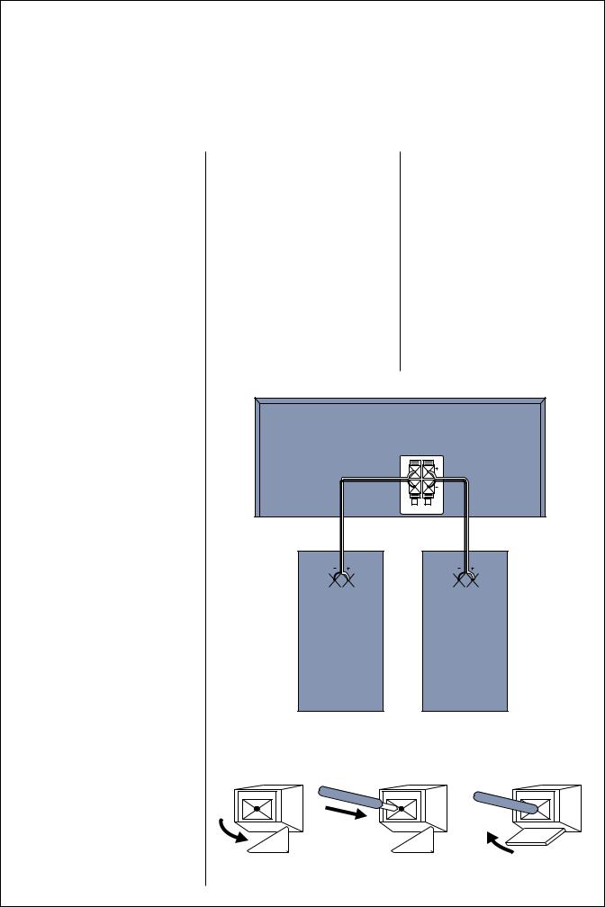
Left and right speakers
Connect the left and right speakers to the ‘Speakers’ jacks on the receiver.
KR-596
RECEIVER
SPEAKERS (8-16
|
|
|
|
|
|
|
|
|
|
|
|
|
|
|
|
|
|
|
|
|
|
|
|
|
|
|
|
|
|
|
|
|
|
|
|
|
|
|
|
|
|
|
|
|
RIGHT |
|
|
LEFT |
|||||||||||
JL-776 |
JL-776 |
SPEAKER |
SPEAKER |
To connect the wire:
|
|
|
|
|
|
|
|
|
|
|
|
|
|
|
|
|
|
|
|
|
|
|
|
|
|
|
|
|
|
|
|
|
|
|
|
|
|
|
|
|
|
|
|
|
|
|
|
|
|
|
|
|
|
|
|
|
|
|
|
|
|
|
|
|
|
|
|
|
|
|
|
|
|
|
|
|
|
|
|
|
|
|
|
|
|
|
|
|
|
|
|
|
|
|
|
|
|
|
|
|
|
|
|
|
|
|
|
|
|
|
|
|
|
|
|
|
|
|
|
1 Unlock the lever |
2 Insert the wire |
3 Lock the lever |
||||||||||||
12.

Connecting your CD player, cassette deck, and optional turntable or VCR |
||||||||
Use the cables that came with the audio and video components. You can connect any turntable that has a magnetic |
||||||||
phono cartridge. |
|
|
|
|
|
|
|
|
TAPE |
|
|
|
|
AUDIO |
|
|
|
|
L |
|
|
|
|
|
|
|
|
|
|
|
|
|
|
|
|
|
|
|
|
|
|
|
L |
|
|
R |
|
|
|
|
|
|
|
REC |
PLAY |
|
|
|
|
OUT IN |
R |
|
|
|
Cassette Deck |
|
|
|
|
||
|
|
|
|
|
VCR |
|
||
|
|
|
|
|
|
|
|
|
|
|
|
|
|
|
|
(optional) |
|
|
ANTENNA |
|
|
|
|
|
|
|
FM75Ω LOOP ANTENNA |
|
|
|
|
|
|
||
FM300Ω |
GND |
AM |
|
|
|
|
|
|
|
|
|
|
|
|
|
||
GND |
|
|
|
|
|
|
|
|
PHONO |
CD |
TAPE |
ADAPTOR |
VIDEO |
|
|
|
|
L |
|
|
|
|
|
|
|
|
R |
|
|
|
|
|
|
|
|
|
|
|
|
|
|
|
R |
L |
|
|
REC |
PLAY |
OUT |
IN |
SYSTEM |
SPEAKERS |
|
|
|
OUT |
IN |
|
|
CONTROL |
(8-16Ω ) |
|
|
|
|
Audio cord |
|
|
KR-596 Receiver |
||
|
|
|
|
|
|
|
||
Turntable (optional) |
|
|
|
|
|
|
||
|
|
|
|
L |
|
|
|
|
|
|
|
|
R |
|
|
|
|
|
|
|
|
LINE OUT |
|
|
|
|
|
|
|
|
|
|
CD Player |
|
|
|
|
|
|
|
|
|
|
13. |
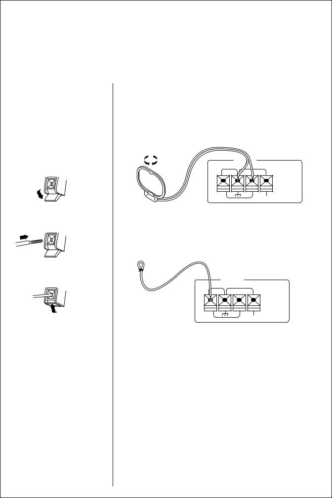
Connecting your antennas
The quality of your FM/AM recep- |
Using the AM indoor loop antenna (supplied) |
tion depends on how well you place |
Place the antenna as far away as possible from the main system, television, |
your antennas. So please follow the |
speaker wires and power cords. |
instructions carefully. |
|
|
Rotate the antenna until you get the best reception. |
Connecting the antenna wires |
|
to the antenna jacks |
|
1 Unlock lever |
ANTENNA |
AM
2 Insert wire
Using the FM indoor antenna (supplied)
Use this antenna until you can install an outdoor antenna. When you do, remove the indoor antenna.
3 Lock lever
ANTENNA
FM75Ω LOOP ANTENNA
|
GND |
FM300Ω |
AM |
|
1Remove the insulation from the wire tip, and twist the wire tightly to get rid of any loose strands.
2Connect the end of the wire to the left-most antenna jack on the receiver.
3Fully extend the antenna, and place it along a wall or bookshelf.
4Adjust the antenna to find the position that provides the best reception.
5Attach the looped end to the wall or bookshelf.
14.
 Loading...