


AUDIO VIDEO SURROUND RECEIVER
KRF-V6070D
INSTRUCTION MANUAL
KENWOOD CORPORATION
About the supplied remote control
Compared to standard remote controls, the remote control supplied with this receiver has several operation modes. These modes enable the remote control to control other audio/video components. In order to effectively use the remote control it is important to read the operating instructions and obtain a proper understanding of the remote control and how to switch its operation modes (etc.).
Using the remote control without completely understanding its design and how to switch the operation modes may result in incorrect operations.
ENGLISH
FRANÇAIS
DEUTSCH
ITALIANO
ESPAÑOL
B60-5332-10 01 ID (E) |
0211 |
ENGLISH
Before applying the power |
Caution : Read this page carefully to ensure safe |
operation. |
Units are designed for operation as follows.
U.S.A. and Canada |
........................................... AC 120 V only |
Australia ........................................................... |
AC 240 V only |
Europe and U.K. ............................................... |
AC 230 V only |
China and Russia ............................................. |
AC 220 V only |
Other countries .......... |
AC 110 - 120 / 220 - 240 V switchable* |
Maintenance of the unit
When the front panel or case becomes dirty, wipe with a soft, dry cloth. Do not use thinner, benzine, alcohol, etc. for these agents may cause discoloration.
How to use this manual
This manual is divided into four sections, Preparations, Operations, Remote Control, and Additional Information.
Preparations
Shows you how to connect your audio and video components to the receiver and prepare the surround processor.
Since this receiver works with all of your audio and video components, we will guide you in setting up your system to be as easy as possible.
Operations
Shows you how to operate the various functions available on the receiver.
In regard to contact cleaner
Do not use contact cleaner because it could cause a malfunction. Be specially careful not to use contact cleaners containing oil, for they may deform the plastic component.
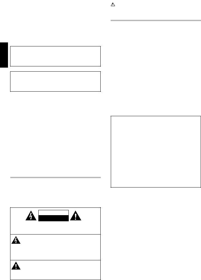
Safety precautions
WARNING :
TO PREVENT FIRE OR ELECTRIC SHOCK, DO NOT EXPOSE THIS APPLIANCE TO RAIN OR MOISTURE.
Remote Control
Shows you how to operate other components using the remote control, as well as a detailed explanation of all remote control operations. Once you have registered your components with the proper setup codes, you’ll be able to operate both this receiver and your other AV components (TV, VCR, DVD player, CD player, etc.) using the remote control supplied with this receiver.
Additional Information
Shows you additional information such as “In case of difficulty” (troubleshooting) and “Specifications”.
Memory back up function
Please note that the following items will be deleted from the unit's memory if the power cord is disconnected from the AC outlet for approximately 1 day.
• Power mode. |
• SUBWOOFER ON/OFF. |
• Input selector settings. |
• SW RE-MIX ON/OFF. |
• Picture output. |
• Distance setting timer. |
• Speaker ON/OFF. |
• Input mode setting. |
• Volume level. |
• Midnight mode setting. |
• BASS, TREBLE, INPUT level. |
• PRO LOGIC II mode setting. |
• TONE ON/OFF. |
• Broadcast band. |
• LOUDNESS ON/OFF. |
• Frequency setting. |
• Dimmer level. |
• Preset stations. |
• MD/TAPE settings. |
• Tuning mode. |
• Listen mode setting. |
• ACTIVE EQ mode. |
• SP SYSTEM. |
• DSP mode. |
• Speaker settings. |
|
CAUTION
RISK OF ELECTRIC SHOCK
DO NOT OPEN
CAUTION: TO REDUCE THE RISK OF ELECTRIC SHOCK, DO NOT REMOVE COVER (OR BACK). NO USER-SERVICEABLE PARTS INSIDE. REFER SERVICING TO QUALIFIED SERVICE PERSONNEL.
THE LIGHTNING FLASH WITH ARROWHEAD SYMBOL, WITHIN AN EQUILATERAL TRIANGLE, IS INTENDED TO ALERT THE USER TO THE PRESENCE OF UNINSULATED “DANGEROUS VOLTAGE” WITHIN THE PRODUCT’S ENCLOSURE THAT MAY BE OF SUFFICIENT MAGNITUDE TO CONSTITUTE A RISK OF ELECTRIC SHOCK TO PERSONS.
THE EXCLAMATION POINT WITHIN AN EQUILATERAL TRIANGLE IS INTENDED TO ALERT THE USER TO THE PRESENCE OF IMPORTANT OPERATING AND MAINTENANCE (SERVICING) INSTRUCTIONS IN THE LITERATURE ACCOMPANYING THE APPLIANCE.
2 EN
Before applying the power
Contents
Caution : Read the pages marked  carefully to ensure safe operation.
|
Before applying the power .............................. |
2 |
|
Safety precautions ............................................. |
2 |
|
How to use this manual ..................................... |
2 |
|
Unpacking .......................................................... |
4 |
|
Preparing the remote control ............................ |
4 |
|
Special features ................................................. |
5 |
|
Names and functions of parts ......................... |
6 |
|
Main Unit ........................................................... |
6 |
|
Remote control unit ........................................... |
7 |
Preparations |
Setting up the system ........................................ |
8 |
|
Connecting audio components .......................... |
9 |
|
Connecting video components ........................ |
10 |
|
Digital connections .......................................... |
11 |
|
Connecting a DVD player (6-channel input) ..... |
12 |
|
Connecting the speakers ................................. |
13 |
|
Connecting the terminals ................................ |
14 |
|
Connecting the antennas ................................. |
14 |
|
Connecting the system control ....................... |
15 |
|
Preparing for surround sound ....................... |
15 |
|
Speaker settings .............................................. |
15 |
|
Normal playback .............................................. |
18 |
|
Preparing for playback ..................................... |
18 |
|
Listening to a source component .................... |
18 |
|
Adjusting the sound ......................................... |
19 |
|
Recording .......................................................... |
20 |
|
Recording audio (analog sources) ................... |
20 |
|
Recording video ............................................... |
20 |
|
Recording audio (digital sources) .................... |
20 |
|
Listening to radio broadcasts ....................... |
21 |
|
Tuning (non-RDS) radio stations ...................... |
21 |
|
Using RDS (Radio Data System) ..................... |
21 |
Operations |
Presetting radio stations manually .................. |
21 |
|
Receiving preset stations ................................ |
22 |
|
Receiving preset stations in order (P.Call) ...... |
22 |
|
Using the RDS Disp. (Display) key .................. |
22 |
|
Presetting RDS stations (RDS AUTO |
|
|
MEMORY) ........................................................ |
23 |
|
Tuning by Program TYpe (PTY search) ............ |
23 |
|
Ambience effects ............................................. |
24 |
|
Surround modes .............................................. |
24 |
|
Surround play ................................................... |
26 |
|
DVD 6-channel playback .................................. |
27 |
|
Convenient functions ....................................... |
27 |
|
Basic remote control operations for other |
|
||
|
components ....................................................... |
29 |
|
|
|
Registering setup codes for other |
|
||
|
components ..................................................... |
29 |
|
|
Remote |
Searching for your code ................................... |
29 |
|
|
Checking the codes ......................................... |
29 |
|
||
Control |
Re-assigning device keys ................................ |
30 |
ENGLISH |
|
|
operations ........................................................ |
35 |
||
|
Operating other components .......................... |
30 |
|
|
|
Setup code chart .............................................. |
31 |
|
|
|
CASSETTE deck, CD player & MD recorder |
|
||
|
Other components’ operations ....................... |
36 |
|
|
|
|
|
|
|
|
In case of difficulty |
38 |
|
|
Additional |
|
|||
Information |
Specifications .................................................. |
40 |
|
|
|
|
|
|
|
3 EN

Before applying the power
Unpacking |
|
Preparing the remote control |
|
Unpack the unit carefully and make sure that all accessories are |
Loading the batteries |
|
|
|
present. |
|
|
|
|
FM indoor antenna (1) |
AM loop antenna (1) |
1 Remove the cover. |
2 Insert the batteries. |
|
|
|
||
ENGLISH |
Remote control unit (1) |
Batteries (R6/AA) (2) |
|
|
|
|
|
||
|
RC-R0825 |
|
|
|
|
|
|
3 Close the cover. |
|
|
|
+ |
|
|
If any accessories are missing, or if the unit is damaged or fails to operate, |
|
|
notify your dealer immediately. If your unit was shipped to you directly, |
|
|
notify your shipper immediately. Kenwood recommend that you retain |
|
|
the original carton and packing materials in case you needs to move or |
|
|
ship the unit in the future. |
• Insert two AA-size (R6) batteries as indicated by the polarity markings. |
|
Keep this manual handy for future reference. |
||
|
Operation
When the STANDBY indicator is lit, the power turns ON when you press the POWER RCVR key on the remote control. When the power comes ON, press the key you want to operate.
Operating range |
Remote sensor |
(Approx.) |
|
6 m
POWER
RCVR
Infrared ray system
+ +
+
• When pressing more than one remote control key successively, press the keys securely by leaving an interval of 1 second or more between keys.
Notes
1. The supplied batteries may have shorter lives than ordinary batteries due to use during operation checks.
2. When the remote-controllable distance gets shorter than before, replace both batteries with new ones.
3. Placing the remote sensor in direct sunlight, or in direct light from a high frequency fluorescent lamp may cause a malfunction.
In such a case, change the location of the system installation to prevent malfunction.
4 EN

Before applying the power
Special features
True home theater sound
This receiver incorporates a wide variety of surround modes to bring you maximum enjoyment from your video software. Select a surround mode according to your equipment or the software you are going to play and enjoy! ¢
Dolby Digital and Dolby Digital EX
The DOLBY DIGITAL mode lets you enjoy full digital surround from software processed in the Dolby Digital format. Dolby Digital provides up to 5.1 channels of independent digital audio for better sound quality and more powerful presence than conventional Dolby Surround. As for Dolby Digital EX, it creates six full-bandwidth output channels from the 5.1 channel sources. This is done using a matrix decoder that derives three surround channels from the two in the original recording. For best result, Dolby Digital EX should be used with movie soundtracks recorded with Dolby Digital Surround EX.
Dolby PRO LOGIC II
DOLBY PRO LOGIC II, whilst totally compatible with its predecessor PRO LOGIC, provides greater advantages in surround sound. It allows user to enjoy the conventional stereo or Dolby Surround with a convincing “5.1 like” presentation. PRO LOGIC II offers special features for controlling the overall spatial, dimensionality and frontal sound field imaging. PRO LOGIC II produces an impressive surround sound from video software marked and three-dimensional space from music CD. When listening to music, you will be able to enjoy the experience of sheer STEREO surround sound.
DTS
DTS (Digital Theater System) is a 5.1 channel digital audio format that provides five full-spectrum channels and one low-frequency (subwoofer) channel for unprecedented clarity, optimum channel separation and a (wide) dynamic range.
In the DTS mode, the 5.1 channel digital input from a DTS CD, LD or DVD disc (carrying the “DTS” marking) can be played in Digital Surround. Important:
When a DTS disc is played on a CD, LD or DVD player, noise may be output from the analog output. It is recommended that you connect the digital output of the player to the digital input of this unit.
DSP surround modes
The DSP (Digital Signal Processor) used for this receiver incorporates a variety of high quality adjustable sound fields, like “ARENA”, “JAZZ CLUB”, THEATER”, STADIUM” and “DISCO”. It is compatible with almost any kind of program source.
DVD 6-channel input
If you own a DVD player equipped with 6-channel output, this receiver allows you to obtain the full surround sound impact of DVD source material featuring multi-channel encoding. Since the source signals are digital and each channel is input independently, the resulting ambience is far superior to what can be achieved with conventional surround sound systems.
ACTIVE EQ
ACTIVE EQ mode will produce a more dynamic sound quality in any condition. You can enjoy a more impressive sound effect when ACTIVE EQ is turned on during Dolby Digital and DTS playback.
Universal IR (InfraRed) remote control
In addition to the basic receiver, the remote control supplied with this receiver can also operate almost all of your remote controllable audio and video components. Just follow the simple setup procedure to register the components you have connected.
RDS (Radio Data System) tuner
The receiver is equipped with an RDS tuner that provides several convenient tuning functions: RDS Auto Memory, to automatically preset up to 40 RDS stations broadcasting different programs; station name display, to show you the name of the current broadcast station; and PTY search to let you tune stations by program type.
PTY (Program TYpe) search
Tune the stations by specifying the type of program you want to hear.
ENGLISH
5 EN
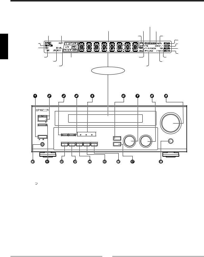
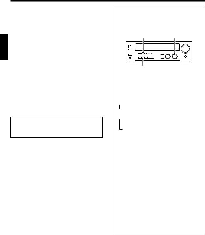
Names and functions of parts
Main Unit
Frequency display, |
AUTO DETECT |
|
Input display, |
||
Preset channel display, |
indicator |
|
Surround mode display |
DTS indicator |
6CH INPUT indicator |
|
Speaker indicator |
MUTE indicator |
|
|
|
|
Band indicators |
|
DIGITAL indicator |
|||
|
|
|
|
|
|
|
|
|
|
|
||
ENGLISH |
|
|
|
|
|
|
|
|
|
|
|
AUTO indicator |
CLIP indicator |
A B |
|
|
|
|
|
|
|
|
|
MEMO. indicator |
|
RDS indicator |
|
|
|
|
|
|
|
|
|
|
||
|
|
|
|
|
|
|
|
|
|
ST. indicator |
||
|
|
|
|
|
|
|
|
|
|
|
||
TONE indicator |
|
|
|
|
|
|
|
DOLBY DIGITAL |
|
TUNED indicator |
||
|
|
Speaker selection indicators |
|
|
DSP indicator |
|||||||
|
LOUDNESS |
indicator |
|
|
indicator |
|
|
|||||
|
|
Input channel indicators |
|
STEREO indicator |
||||||||
|
|
|
|
|
|
|||||||
|
96kHzfs indicator |
Output channel indicators |
|
PRO LOGIC |
|
|||||||
|
|
|
|
|
|
|
|
|
Display |
indicator |
|
|
|
|
|
|
|
|
|
|
|
|
|
|
|
|
|
|
|
|
|
|
|
|
|
|
|
VOLUME CONTROL |
|
|
STANDBY |
|
|
|
|
|
|
|
|
|
|
|
ON ⁄ STANDBY |
|
|
|
|
|
|
|
|
|
|
|
|
SPEAKERS ON ⁄ OFF |
|
|
|
|
|
|
|
|
|
|
|
|
|
|
|
DIMMER |
LISTEN MODE |
ACTIVE EQ |
DTS |
DOLBY |
|
MULTI CONTROL |
DOWN |
UP |
|
|
POWER |
|
|
INPUT SELECTOR |
|
||||||
|
|
|
|
|
|
|
DIGITAL EX |
|
SOUND |
|
|
|
|
|
|
|
|
|
|
|
|
|
|
|
|
|
|
|
|
|
|
|
|
|
|
|
|
MUTE |
|
|
ON OFF |
|
|
|
|
|
|
|
|
|
|
|
|
PHONES |
|
ACTIVE EQ |
INPUT MODE |
BAND |
AUTO |
MEMORY |
|
SETUP |
|
|
1 POWER ON/OFF key |
% |
||
Use to turn the main power ON/OFF. |
|
||
2 ON/STANDBY |
|
key |
% |
|
|||
|
|||
Use to switch the power ON/STANDBY when |
|||
the POWER is turned ON. |
|
||
STANDBY indicator |
|
||
3 DIMMER key |
|
||
Use to select the REC MODE. |
) |
||
Use to adjust the brightness of the display. |
|||
|
|
|
• |
4 LISTEN MODE key |
§ |
||
Use to select the listening mode.
5Surround LED (light-emitting diode) indicators
ACTIVE EQ mode LED indicator (
Lights when the receiver is in the ACTIVE EQ mode.
DTS mode LED indicator §
Lights when the receiver is in the DTS mode.
DOLBY DIGITAL EX mode LED indicator
§
Lights when the receiver is in the Dolby
Digital EX mode. |
|
6 SOUND key |
¶ |
Use to adjust the sound quality and the |
|
ambience effects. |
|
7 MULTI CONTROL knob |
% |
Use to control a variety of settings. |
|
8 INPUT SELECTOR knob |
* |
Use to select the input sources. |
|
9 VOLUME CONTROL knob |
* |
0 PHONES jack |
( |
Use for headphone listening. |
|
! SPEAKERS ON/OFF key |
* |
Use to turn the speakers ON/OFF. |
|
@ ACTIVE EQ key |
( |
Use to select ACTIVE EQ setting. |
|
# INPUT MODE key |
8 |
Use to switch between full auto, digital and analog inputs.
$ BAND key |
¡ |
Use to select the broadcast band. |
|
%AUTO key
Use to change “TAPE” indication to “MD”.
*
Use to select the auto tuning mode. ¡
^ MEMORY key |
¡ |
Use to store radio stations in the preset |
|
memory. |
|
& SETUP key |
% |
Use to select the speakers' settings etc. |
|
* MUTE key |
( |
Use to temporarily mute the sound.
Standby mode
While the standby indicator is lit, a small amount of power is supplied to the system to back-up the memory. This is called standby mode. Under the condition, the system can be turned ON by the remote control unit.
Connection at POWER ON/OFF key
The power in this equipment will not be completely cut off from the AC wall outlet when the main switch is turned OFF.
6 EN
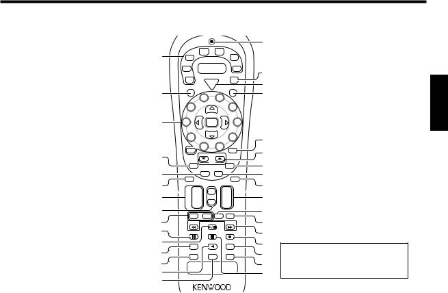
Names and functions of parts
Remote control unit
This remote control unit can be use not only for Kenwood products but also for non-Kenwood products by setting the appropriate manufacturer’s setup
codes. ⁄
^
|
|
|
TUNER |
DVD |
|
|
|
1 |
|
|
6CH |
|
|
|
|
|
|
|
|
|
|
||
VID1 |
|
|
CD |
|
|||
|
|
DVD |
|
||||
|
VID2 |
|
|
|
|
MD |
|
|
|
|
|
TAPE |
& |
||
|
|
|
|
|
|
||
|
PHONO |
POWER |
|
TV |
* |
||
|
C |
Po |
RCVR |
|
Po |
|
|
|
w |
V |
w |
|
|||
|
R |
|
e |
|
e |
|
|
2 |
S |
|
r |
|
|
|
( |
|
|
|
|
|
|
||
|
|
|
4 |
5 |
|
|
|
|
|
3 |
Multi |
|
6 |
|
|
|
|
|
|
|
|
|
|
1 Source keys (PHONO, VID2, VID1, TUNER, DVD/6CH, CD/DVD, MD/TAPE) ª
When press and hold for more than 3 seconds, they are used to select the registered components.
Input Selector keys (PHONO, VID2, VID1,
TUNER, DVD/6CH, CD/DVD, MD/TAPE)
*
When press and release in less than 3 seconds, they are used to select the input sources.
2SRC (source) Power key
Use to turn the other source components on and off.
3 Numeric keys |
ª |
Provide functions identical to those of the |
|
original remote control supplied with the |
|
component you are controlling. |
|
Multi (multi control) %/fi keys |
% |
Use to control a variety of settings. |
|
Use to operate other components. |
|
P.Call @/# keys |
™ |
If tuner is selected as the input source, these keys function as preset channel call keys.
Enter key
Use to operate other components.
4Return key
Use to operate the DVD component.
Exit key
Use to operate other components.
5Disc Skip key
If CD is selected as the input source, this key functions as the multi-CD player disc skip
key.
Last/A/B key
If TAPE is selected as the input source, this is A and B deck of a double cassette deck. Use to operate other components.
6 Disc Sel. key
Use to operate other components.
Input Sel. key
Use to operate other components.
7CH +/– keys
Use to select the channels.
4/¢ keys
If CD, MD or DVD is selected as the input source, these keys function as skip keys.
3 |
2 |
|
P. Call |
Enter |
Call .P |
7 |
|
|
|
|
|
1 |
|
|
Multi |
|
8 |
|
|
|
|
|
|
|
|
) |
|
||
|
|
|
|
|
|
|
|
|
|
|
+ 10 |
|
0 |
|
9 |
+100 |
¡ |
|
|
4 |
|
|
|
|
|
||||
|
|
RDS Disp. |
|
PTY |
TV Mute |
|
|||
|
|
|
|
|
Page |
|
|
™ |
|
|
|
Return |
Last/A/B |
|
OSD |
|
|||
5 |
|
Exit |
|
Guide |
|
|
|||
|
Disc Skip Menu |
£ |
|
||||||
|
|
|
|
||||||
6 |
Disc Sel. |
|
|
|
|
Mute |
¢ |
|
|
Input Sel. |
|
|
|
|
|
|
|||
7 |
¢ |
+ |
|
|
Tone |
|
+ |
|
|
|
CH |
Sound |
VOL |
∞ |
|
||||
|
|
– |
|
|
– |
|
|
||
8 |
4 |
|
|
|
|
§ |
|
||
|
|
TV |
|
|
|
Bass |
|
||
|
|
|
|
TV Input |
|
|
|||
|
|
– VOL |
+ |
Boost |
|
|
|||
9 |
|
|
|
¶ |
|
||||
|
Tune – |
|
|
Band |
|
Tune + |
|
||
0 |
Dimmer |
|
|
Auto |
|
Top Menu |
• |
|
|
! |
|
|
|
Info/Flip |
|
Setup |
ª |
|
|
|
Input |
|
|
|
|
||||
|
|
|
|
|
|
Loudness |
If the name of a function is different on |
||
|
|
Mode |
|
|
|
|
|
||
@ |
|
Mode |
|
|
EQ |
|
Setup |
º |
the receiver and on the remote control, |
|
Listen |
|
|
Active |
|
Remote |
|
||
#⁄ the name of the remote control key in
$ |
¤ |
this manual is indicated in parentheses. |
% |
|
|
|
|
8 Tone key |
( |
Use to switch the status of TONE control. |
|
Sound key |
¶ |
Use to adjust the sound quality and ambience effects.
9 TV VOL +/– keys
Use to adjust the TV’s volume.
08 key
Use to operate other components.
Dimmer key •
Use to adjust the brightness of the display.
!6 key
If CD is selected as the input source, this key functions as the play/pause key. If MD or TAPE is selected as the input source, this key functions as the play key.
Band key |
¡ |
Use to select the broadcast band. |
|
@ Input Mode key |
8 |
Use to switch between full auto, digital and |
|
analog inputs. |
|
# Listen Mode key |
§ |
Use to select the listening mode.
$2 key
If TAPE is selected, this key functions as reverse play key.
Info/Flip key
Use to operate other components.
% Active EQ key |
( |
Use to select ACTIVE EQ setting. |
|
^LED (light-emitting diode) indicator
Blinks to show that signals are being transmitted.
&TV key
Use to select the TV equipment.
* POWER RCVR (receiver) key |
% |
Use to turn the receiver on and off. |
|
( TV Power key |
|
Use to turn the TV on and off. |
|
)+100 key
Use to select the disc number with the multiCD player.
TV Mute key
Use to temporarily mute the TV sound.
¡Page ∞/5 keys
Use to operate other components.
RDS Disp. key |
™ |
Use for RDS function. |
|
PTY key |
£ |
Use for PTY search. |
|
™OSD (on screen display) key
Use to operate the DVD component.
Guide key
Use to operate other components.
£Menu key
Use to operate other components.
¢ Mute key |
( |
Use to temporarily mute the sound. |
|
∞VOL +/– keys
Use to adjust the receiver’s volume.
§TV Input key
Use when in TV operation.
¶ Bass Boost key (
Use to select the maximum adjustment setting for the low frequency range.
•1/¡ key
If CD, MD or TAPE is selected as the input
source, these keys function as search key.
Tune –/+ key
Use to operate the tuner mode.
ª¶ key
If MD or TAPE is selected, this key functions as record key.
If VCR is selected, this key functions as
record key when it is pressed twice sequentially.
Top Menu key |
|
Use to operate other components. |
|
Setup key |
% |
Use to select the speakers' settings etc. |
|
º Loudness key |
( |
Use to switch the status of LOUDNESS.
⁄Remote Setup key
Use to register other components.
¤7 key
If CD, MD or TAPE is selected as the input source, this key functions as the stop key.
Auto key |
¡ |
Use to select the auto tuning mode. |
|
ENGLISH
7 EN
Setting up the system
|
Make connections as shown in the following pages. |
|
When connecting the related system components, be |
|
sure to refer to the instruction manuals supplied with |
|
the components you are connecting. |
|
Do not connect the power cord to a wall outlet until all |
|
connections are completed. |
ENGLISH |
|
interference. |
|
|
Notes |
|
1. Be sure to insert all connection cords securely. If their connections are |
|
imperfect, the sound may not be produced or there will be noise |
|
2. Be sure to remove the power cord from the AC outlet before plugging |
|
or unplugging any connection cords. Plugging/unplugging connection |
|
cords without disconnecting the power cord can cause malfunctions |
|
and may damage the unit. |
|
3. Do not connect power cords from components whose power |
|
consumption is larger than what is indicated on the AC outlet at the |
|
rear of this unit. |
|
Analog connections |
|
Audio connections are made using RCA pin cords. These cables transfer |
|
stereo audio signal in an “analog” form. This means the audio signal |
|
corresponds to the actual audio of two channels. These cables usually |
|
have 2 plugs at each end, red for the right channel and white for the left |
|
channel. These cables are usually packed together with the source unit, |
|
or are available at your local electronics retailer. |
Microcomputer malfunction
If operation is not possible or an erroneous display appears, even though all connections have been made properly, reset the microcomputer by referring to “In case of difficulty”. °
Input mode settings
CD/DVD, VIDEO2 and DVD/6CH inputs each include jacks for digital audio input and analog audio input.
After completing connections and turning on the receiver, follow the steps below.
LISTEN MODE INPUT SELECTOR
INPUT MODE
1Use the INPUT SELECTOR knob to select CD/DVD, VIDEO2, DVD/6CH.
2Press the INPUT MODE key.
Each press switches the setting as follows:
In DTS play mode
 1 F-AUTO (digital input, analog input) 2 D-MANUAL (digital input)
In CD/DVD, VIDEO2, DVD/6CH play mode
 1 F-AUTO (digital input, analog input) 2 D-MANUAL (digital input)
3 6CH INPT (DVD/6CH input)
4 ANALOG (analog input)
Digital input:
Select this setting to play digital signals from a DVD, CD, or LD player.
Analog input:
Select this setting to play analog signals from a cassette deck, VCR, or record player.
Auto detect:
In “F-AUTO” (full auto) mode (AUTO DETECT and DIGITAL indicators light up), the receiver detects the digital or analog input signals automatically. Priority is given to digital signal during input mode selection. The receiver will select the input mode and listening mode automatically during playback to match the type of input signal (Dolby Digital, PCM, DTS ) and the speaker setting. The initial factory setting is full auto.
To keep the receiver set to the currently selected listening mode, use the INPUT MODE key to select “D-MANUAL” (digital manual). However, even when this setting is selected, there may be cases in which the listening mode is selected automatically to match a Dolby Digital source signal depending on the combination of listening mode and source digital.
In D-MANUAL mode, if the audio reproduction stops in the middle due to change in the input signals etc, press the LISTEN MODE key. If the INPUT MODE key is pressed quickly, sound may not be produced. Press the INPUT MODE key again.
8 EN
Setting up the system
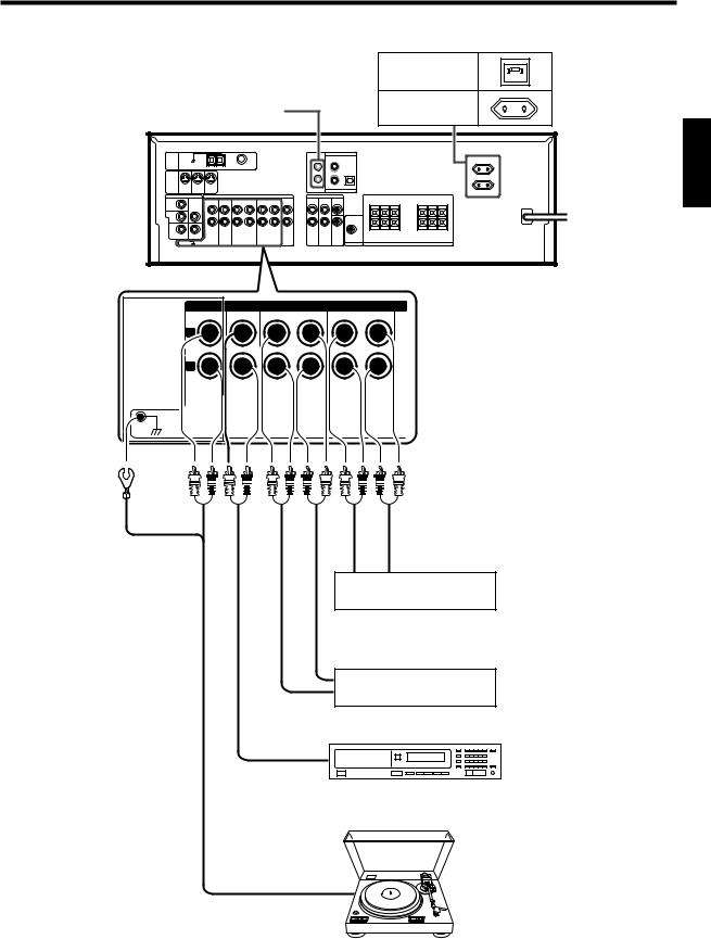
Connecting audio components
Shape of AC outlets
|
|
U.K. |
|
SYSTEM CONTROL |
EUROPE |
|
|
jacks |
% |
|
|
|
|
|
ENGLISH |
|
|
+ |
+ |
|
|
|
To AC wall outlet |
|
|
- |
- |
|
|
AUDIO |
|
L |
|
|
|
R |
|
|
|
PHONO CD/DVD REC OUT PLAY IN REC OUT PLAY IN |
|
MD / TAPE |
VIDEO1 |
GND
IN OUT
Video component )
IN OUT
Cassette deck or MD recorder
OUT
CD or DVD player
OUT
Moving coil (MC) cartridge record player cannot be used directly from the receiver unit. It can only be used when another equalizer amplifier is connected.
Record player
9 EN

Setting up the system
ENGLISH
Connecting video components
About the S-VIDEO jacks
S-VIDEO
Use the S-VIDEO jacks to make connections to video components with S-VIDEO IN/OUT jacks.
•If you use the S-VIDEO jacks to connect your video playback components, be sure to use the S-VIDEO jacks when connecting your monitor and video recording components.
S-VIDEO jacks
S-VIDEO
VIDEO 2 |
DVD |
MONITOR |
|
IN |
IN |
OUT |
|
|
|
+ |
+ |
|
|
- |
- |
|
VIDEO |
|
|
DVD |
|
AUDIO |
|
IN |
|
MONITOR |
|
|
|
OUT |
|
VIDEO 2
IN
|
|
REC OUT PLAY IN |
PLAY IN |
VIDEO 1 |
VIDEO 1 |
VIDEO1 |
VIDEO 2 |
IN |
OUT |
|
|
VIDEO
IN
Monitor TV
VIDEO |
|
|
IN/OUT |
Video inputs |
|
|
(Yellow RCA pin cords) |
IN |
|
IN |
|
|
Video deck |
|
|
OUT |
OUT |
|
Video inputs and |
Audio inputs |
|
outputs |
and outputs |
|
(Yellow RCA pin cords) |
|
|
DVD player or LD player |
OUT |
|
OUT |
A video component with digital audio outputs should be connected to the VIDEO 2 jacks.
AUDIO IN/OUT
10 EN
Setting up the system
Digital connections
The digital in jacks can accept DTS, Dolby Digital, or PCM signals. Connect components capable of outputting DTS, Dolby Digital, or standard PCM (CD) format digital signals.
If you have connected any digital components to the receiver, be sure to read the “Input mode settings” section carefully. |
8 |
|
ENGLISH |
+ |
+ |
- |
- |
COAXIAL |
OPTICAL |
VIDEO 2 |
CD / DVD |
DVD / 6CH
DIGITAL IN
OPTICAL DIGITAL OUT (AUDIO)
Optical fiber cable
CD or DVD player
COAXIAL DIGITAL OUT (AUDIO)
RF digital demodulator (DEM-9991D)
(sold separately)
DOLBY DIGITAL RF
OUT (AUDIO)
PCM OUT
COAXIAL DIGITAL OUT (AUDIO)
Component with DTS,
Dolby Digital, or PCM
COAXIAL DIGITAL OUT
Connect the video signal and analog audio signals to the VIDEO 2 jacks. (See “Connecting video components”.)
0
LD player
To connect an LD player with a DIGITAL RF OUT, connect the LD player to the KENWOOD RF digital demodulator (DEM-9991D). Next, connect the DIGITAL OUT jacks of the demodulator to the DIGITAL IN jacks of the receiver.
Connect the video signal and analog audio signals to the VIDEO 2 jacks. (See “Connecting video components”.)
11 EN

Setting up the system
Connecting a DVD player (6-channel input)
If you have connected a DVD player to the receiver with digital connection, be sure to read the “Input mode settings” section carefully. |
8 |
ENGLISH |
DVD |
|
|
IN |
|
|
+ |
+ |
|
- |
- |
VIDEO |
DVD / 6CH INPUT |
COAXIAL |
OPTICAL |
DVD |
CENTER |
VIDEO 2 |
CD / DVD |
|
|
|
|
IN |
MONITOR |
|
|
|
|
|
|
VIDEO 2 |
OUT |
|
|
|
|
|
|
IN |
|
|
|
|
SUB |
DVD / 6CH |
|
|
FRONT SURROUNDWOOFER |
|
|
|
|
DIGITAL IN |
|
VIDEO 1 |
VIDEO 1 |
|
|
IN |
OUT |
|
|
VIDEO OUT |
FRONT |
SURROUND |
SUBWOOFER |
(Yellow RCA |
OUT L/R |
OUT L/R |
OUT |
pin cord) |
|
|
|
|
DVD player |
|
CENTER OUT |
S-VIDEO COAXIAL
OUT DIGITAL OUT (AUDIO)
S-VIDEO cord
CAUTION
Be sure to adhere to the following, or proper ventilation will be blocked causing damage or fire hazard.
•Do not place any object impairing heat radiation onto the top of the unit.
•Leave a space around the unit (from the largest outside dimension including projection) equal or greater than, shown below.
Top panel : 50 cm |
Side panel : 10 cm |
Back panel : 10 cm |
12 EN
Setting up the system
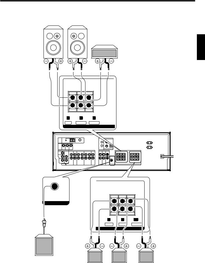
Connecting the speakers
Front Speakers
Right |
Left |
Center
Speaker
|
FRONT |
CENTER |
|
|
|
+ |
|
|
|
- |
|
R |
L |
C |
|
RED |
WHITE |
GREEN |
|
|
|
SPEAKERS (6-16Ω) |
|
|
|
+ |
+ |
|
|
- |
- |
SURROUND
SURROUND BACK
SUB WOOFER
+
PRE OUT
-
R |
L |
SB |
GRAY BLUE BROWN
SPEAKERS (6-16Ω)
Powered sub woofer
Right |
Left |
Surround |
Surround Speakers |
|
Back |
|
|
(Be sure to connect both surround speakers)
ENGLISH
13 EN
Setting up the system
Connecting the terminals
1 Strip coating. 2 Push the lever.
ENGLISH |
3 Insert the cord. |
4 Return the lever. |
|
•Never short circuit the + and – speaker cords.
•If the left and right speakers are connected inversely or the speaker cords are connected with reversed polarity, the sound will be unnatural with ambiguous acoustic imaging. Be sure to connect the speakers correctly.
Speaker impedance
After confirming the speaker impedance indications printed on the rear panel of the receiver, connect speakers with matching impedance ratings. Using speakers with a rated impedance other than that indicated on the rear panel of the receiver could result in malfunctions or damage to the speakers or receiver.
Speaker placement
Center speaker
 Subwoofer Front
speaker
Listening
position
Surround speaker

 Surround back speaker
Front speakers : Place to the front left and right of the listening position. Front speakers are required for all surround modes. Center speaker : Place front and center. This speaker stabilizes the sound image and helps recreate sound motion. Required for surround playback.
Surround speakers : Place to the direct left and right, or slightly behind, the listening position at even heights, approximately 1 meter above the ears of the listeners. These speakers recreate sound motion and atmosphere. Required for surround playback.
Subwoofer : Reproduces powerful deep bass sounds.
Surround back speaker : Place the speaker directly at the rear of the listening position. The optimum position depends mainly on the room condition.
•Although the ideal surround system consists of all the speakers listed above, if you don't have a center speaker or a subwoofer, you can divide those signals between the available speakers in the
speaker settings steps to obtain the best possible surround reproduction from the speakers you have available. %
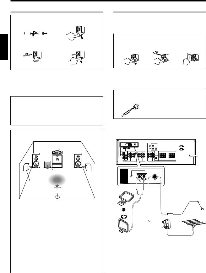
Connecting the antennas
AM loop antenna
The supplied loop antenna is for use indoors. Place it as far as possible from the receiver, TV set, speaker cords and power cord, and adjust the direction for best reception.
AM antenna terminal connections
1 Push lever. |
2 Insert cord. |
3 Release lever. |
FM indoor antenna
The supplied indoor antenna is for temporary use only. For stable signal reception we recommend using an outdoor antenna. Disconnect the indoor antenna when you connect one outdoors.
FM antenna terminal connections
Insert cord.
FM outdoor antenna
Lead the 75Ω coaxial cable connected to the FM outdoor antenna into the room and connect it to the FM 75Ω terminal.
+ |
+ |
- |
- |
ANTENNA
GND
AM |
FM |
|
75Ω |
Attach to the stand
FM indoor antenna
FM outdoor antenna
|
Use an antenna |
AM loop antenna |
adapter |
(Commercially |
|
|
available) |
14 EN
Setting up the system
Connecting the system control
Connecting system control cords after connecting a KENWOOD audio component system lets you take advantage of convenient system control operations.
This unit is compatible only with the [SL-16] mode. The system control operation is not available if the unit is connected in the [XS8], [XS], or [XR] connection mode.
If your component has the mode select switch, set the connected components to the [SL16] mode.
SYSTEM CONTROL cord
SYSTEM CONTROL
•You may connect the system control cord to either the up or down jack.
EXAMPLE: [SL16] mode connections
The underlined portion represents the setting of the system control mode.
[SL16] |
Receiver |
|
|
|
|
|
SYSTEM |
[SL16] [XS] [XS8] [XR] |
Cassette deck |
|
CONTROL |
|
|||
|
or MD recorder |
|
cord |
|
|
|
|
[SL16] [XS] [XS8] |
CD player |
|
|
|
|
||
|
|
|
|
[XS] |
Record player |
|
|
|
|
|
|
•In order to take advantage of the system control operations, the components must be connected to the correct jacks. To use a CD player it must be connected to the CD jacks. To use a cassette deck (or MD recorder) it must be connected to the MD/TAPE jacks. When using more than one CD player (etc.) only the one connected to the specified jacks may be connected for system control.
•Some CD players and cassette decks are not compatible with the [SL16] system control mode. Do not make system connections with equipment that is not [SL16] compatible.
•Some MD players are not system control compatible. You cannot make system control connections to this kind of equipment.
Notes
1.[SL16] equipment cannot be combined with [XR], [XS], and [XS8] equipment for system operations. If your equipment consists of this kind of combination, please do not connect any system control cords. Even without system control cords, normal operations can be carried out without affecting performance.
2.Do not connect system control cords to any components other than those specified by KENWOOD. It may cause a malfunction and damage your equipment.
3.Be sure the system control plugs are inserted all the way in to the system control terminals.
System control operations
Remote Control
Lets you operate this unit with the system remote supplied with the receiver.
Automatic Operation
When you start playback from a source component, the input selector on this unit switches to that component automatically.
Synchronized Recording
Lets you synchronize recording with the start of playback when recording from CD, MD or analog discs.
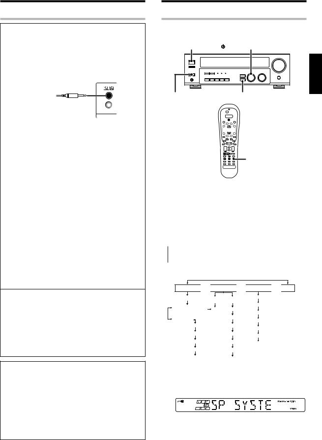
Preparing for surround sound
Speaker settings
To enable you to obtain optimum enjoyment from the receiver’s listening modes, make sure to complete the speaker settings (subwoofer, front, center, and surround speakers) as described below.
ON/STANDBY |
MULTI CONTROL |
ENGLISH
POWER |
SETUP |
ON/OFF |
|
POWER RCVR 


 Multi %/ fi
¢ + |
+ |
4
+
Setup |
1Turn on the power to this receiver by pressing POWER ON/OFF and ON/STANDBY  or POWER RCVR key.
2For the remote control, press and hold the TUNER key for more than 3 seconds to switch to receiver mode.
3Press the SETUP key to enter the SETUP mode and use the MULTI CONTROL knob or Multi %/ fikeys for the following displays.
 1 SP SETUP 2 TESTTONE 3 DISTANCE
  4 EXIT
The flow of the SETUP is as follows;
SP SETUP 
 TESTTONE
 DISTANCE
 EXIT
EXIT
SP System |
AUTO |
|
MANUAL |
Front Left |
||
|
|
|
|
|||
2Way 2Speaker |
|
|
L |
L |
Center |
|
|
|
Front Right |
||||
2Way 3Speaker |
|
|
C |
C |
||
Others |
|
|
R |
Surround Right |
||
|
|
|
||||
|
|
|
SR |
|
||
Subwoofer |
|
|
R |
Surround Back |
||
|
|
|
SB |
|
||
Front |
|
|
|
|
||
|
|
SL |
SR |
Surround Left |
||
|
|
|
SW |
|
||
|
|
|
|
|
||
Center |
|
SB |
Subwoofer |
|||
|
|
|
||||
Surround |
SL |
|
|
Subwoofer Re-mix |
SW |
|
4Select a speaker system.
1 Select SP SETUP and press the SETUP key again so that the speaker system indication “SP SYSTEM” scrolls across the display.
Continued to next page
15 EN
Preparing for surround sound
ENGLISH
2Use the MULTI CONTROL knob or Multi %/fi keys to select the speaker system setting.
1 |
2WAY 2SPKR : For selected Kenwood speaker – for example, |
|
|
|
KS-307HT. |
2 |
2WAY 3SPKR : For selected Kenwood speaker – for example, |
|
|
|
KS-707HT. |
3 |
OTHERS |
: For general speakers. |
•The selection of 2WAY 2SPKR or 2WAY 3SPKR should only be used with 6 channels speaker system setting.
•When the setting 2WAY 2SPKR or 2WAY 3SPKR is selected, the procedure skips to step 5.
3For general speaker setting, use the MULTI CONTROL knob or Multi %/fi keys to select OTHERS and press the SETUP key again.
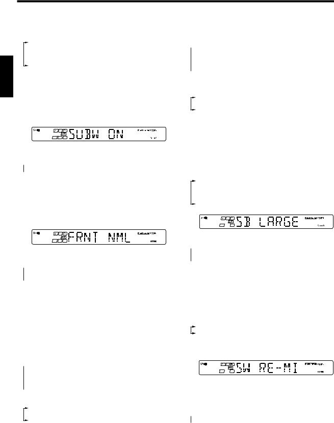
• The subwoofer setting indication “SUBW ON” appears.
4Use the MULTI CONTROL knob or Multi %/fi keys to select the appropriate subwoofer setting.
 1 SUBW ON : Subwoofer setting mode to the receiver is ON.
  2 SUBW OFF : Subwoofer setting mode to the receiver is OFF.
•The initial setting is “SUBW ON”.
•When the setting “SUBW OFF” is selected, the front speakers are automatically set to “FRNT LRG” and the procedure skips to step 7.
Before step 7, press the SETUP key to accept the setting.
•When subwoofer output sound is required, select “FRNT NML”.
5Press the SETUP key to accept the setting.
• The front speakers setting indication “FRNT NML” appears.
6Use the MULTI CONTROL knob or Multi %/fi keys to select the appropriate front speakers setting.
 1 FRNT NML (normal) : Average size front speakers are connected to the receiver.
 2 FRNT LRG (large) : Large front speakers are connected to the receiver.
•For “FRNT LRG” selection, no sound will be heard from subwoofer speaker even when it is set to ON. However, if you select “SW RE-MIX ON” when subwoofer is selected, you will be able to hear sound from the subwoofer.
When in STEREO mode, the sound goes directly to front speaker.
7Press the SETUP key to accept the setting.
• The center speaker setting indication “CNTR NML” appears.
8Use the MULTI CONTROL knob or Multi %/fikeys to select the appropriate center speaker setting.
If you have selected “LRG” as the front speakers setting,
 1 CNTR NML (normal) : An average size center speaker is connected to the receiver.
2 CNTR LRG (large) : A large center speaker is connected to the receiver.
 3 CNTR OFF : Center speaker setting mode to the receiver is OFF.
If you have selected “NML” as the front speakers setting,
1 |
CNTR ON |
: Center |
speaker setting mode to the |
|
|
receiver is ON. |
|
2 |
CNTR OFF |
: Center |
speaker setting mode to the |
|
|
receiver is OFF. |
|
9Press the SETUP key again to accept the setting.
•The surround speaker setting indication “SURR NML” appears.
0Use the MULTI CONTROL knob or Multi %/fi keys to select the appropriate surround speaker setting.
If you have selected “LRG” as the center speaker setting,
 1 SURR NML (normal) : Average size surround speakers are connected to the receiver.
2 SURR LRG (large) : Large surround speakers are connected to the receiver.
 3 SURR OFF : Surround speaker setting mode to the receiver is OFF.
If you have selected other than “LRG” as the center speaker setting,
1 |
SURR ON : Surround speaker setting mode to the receiver is |
|
ON. |
2 |
SURR OFF : Surround speaker setting mode to the receiver is |
|
OFF. |
•When the setting “SURR OFF” is selected, the procedure skips to step %.
!Press the SETUP key to accept the setting.
•The surround back speaker setting indication “SB” appears.
@Use the MULTI CONTROL knob or Multi %/fi keys to select the appropriate surround back speaker setting.
If you have selected “LARGE” as the surround speaker setting,
1 |
SB NORMAL : Average size surround back speaker is |
|
|
|
connected to the receiver. |
2 |
SB LARGE |
: Large surround back speaker is connected to |
|
|
the receiver. |
3 |
SB OFF |
: Surround back speaker setting mode to the |
|
|
receiver is OFF. |
If you have selected “NORMAL” as the surround speaker setting,
 1 SB ON
 2 SB OFF
#Press the SETUP key to accept the setting.
•The surround mix setting indication “SURR MIX” appears.
•SURR MIX is when the SL and SR speakers signals are mixed to produce sound from the surround back speaker which would enable the listener to enjoy sound coming from the back.
$Use the MULTI CONTROL knob or Multi %/fi keys to select the surround mix setting.
1 |
MIX OFF |
: Surround mix setting mode is OFF. |
2 |
MIX ON |
: Surround mix setting mode is ON. |
%Press the SETUP key again to accept the setting.
•The subwoofer re-mix setting indication “SW RE-MIX” scrolls across the display.
•If subwoofer is turned OFF, subwoofer re-mix setting is not visible.
^Use the MULTI CONTROL knob or Multi %/fi keys to select the appropriate subwoofer re-mix setting.
 1 RMX ON : Subwoofer re-mix set mode to the receiver is ON.
  2 RMX OFF : Subwoofer re-mix set mode to the receiver is OFF.
&Press the SETUP key to accept the setting.
•The receiver enters the speaker volume level adjustment mode.
•In step 5 and 6, indications appear only for the selected channels of the speakers that require adjusting.
16 EN
Preparing for surround sound
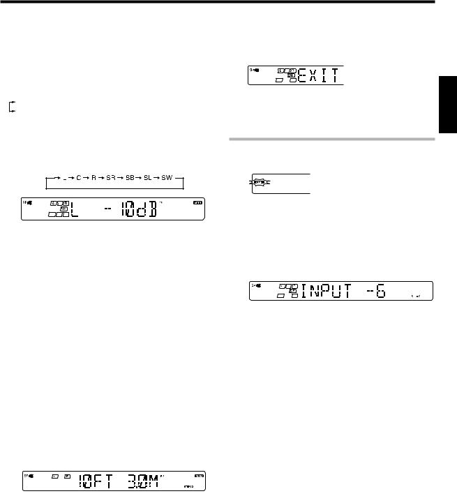
5Adjust the speaker volume level.
From your usual listening position, adjust the volume levels. The volume levels from each speaker should be the same.
1Press the SETUP key to begin TEST TONE.
The selection of AUTO/MANUAL TEST TONE is done by the MULTI CONTROL knob or Multi %/fi keys.
1 AUTO
2 MANUAL
2Press the SETUP key again to select either AUTO or MANUAL.
Use the MULTI CONTROL knob or Multi %/fi keys to adjust the volume level of the test tone output from the speaker channel to be adjusted.
5Repeat steps 3 and 4 to input the distance for each of the speakers.
6 Setup is complete when the EXIT indication appears.
•The speakers you have selected should appear on the display. Confirm that all the speakers have been correctly selected.
7 Press the SETUP key to exit the SETUP mode.
Input level adjustment (analog sources only)
For AUTO selection, the test tone is heard from the speakers |
If the input level of an analog source signal is too high, the CLIP indicator |
|
will blink to indicate the source signal. Adjust the input level. |
||
in the following sequence for 2 seconds each: |
||
|
||
|
1 Use the INPUT SELECTOR knob to select the source of which the |
|
|
input level you want to adjust. |
•If you change the volume level settings for the speakers while listening to music, the settings referred to on this page are also
changed. |
¶ |
•If any of the speaker is set as OFF during SP SETUP, the TEST TONE adjustment for the speaker will be skipped.
3Press the SETUP key.
•The test tone is turned off. The receiver enters the mode for inputting the distance to the speakers.
4For MANUAL selection, press the SETUP key each time to select the speaker channel.
6Input the distance to the speakers.
1Select the DISTANCE from the set up displays and press the SETUP key again.
2Measure the distance from the listening position to each of the speakers.
Jot down the distance to each of the speakers.
Distance to Front left speaker (L) |
: ____ feet (meters) |
Distance to Center speaker (C) |
: ____ feet (meters) |
Distance to Front right speaker (R) |
: ____ feet (meters) |
Distance to Surround right (SR) |
: ____ feet (meters) |
Distance to Surround back (SB) |
: ____ feet (meters) |
Distance to Surround left (SL) |
: ____ feet (meters) |
Distance to Subwoofer (SW) |
: ____ feet (meters) |
3Use the MULTI CONTROL knob or Multi %/fikeys to select the distance to the front speakers.
• You can store a separate input level for each input source.
2Press the SOUND key repeatedly until the “INPUT” indication appears.
3Use the MULTI CONTROL knob or Multi %/fi keys to adjust the input level.
•The input level may be adjusted to any one of three settings: 0dB, -3dB, and -6dB. (The initial setting is 0dB.)
4 Press the SOUND key again to return to the input indication.
ENGLISH
Indication in feet Indication in meters
•The allowable setting range is 1 to 30 feet (0.3m to 9.0m), adjustable in 1 foot (0.3m) increments.
4 Press the SETUP key to accept the settings.
17 EN
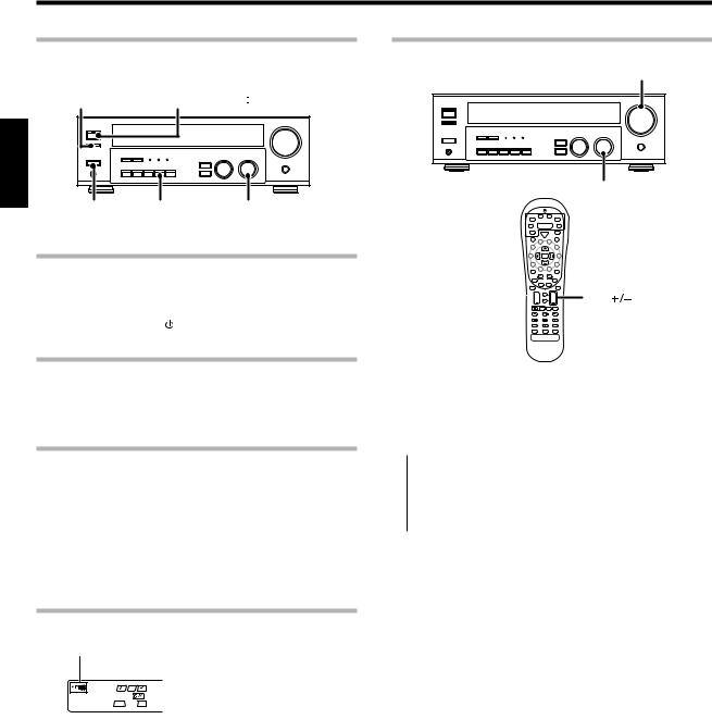
Normal playback
Preparing for playback
Some preparatory steps are needed before starting playback.
SPEAKERS
ON/OFF ON/STANDBY 
ENGLISH
POWER |
AUTO |
INPUT SELECTOR |
ON/OFF |
|
|
Turning on the receiver
1 Turn on the power to the related components.
2 Turn on the power to this receiver by pressing POWER ON/
OFF and ON/STANDBY key.
Selecting the input mode
If you have selected a component connected to the CD/DVD, VIDEO2, DVD/6CH jacks, make sure that the input mode setting is correct for the
type of audio signal to be used. |
8 |
Selecting MD/TAPE
Select the source name corresponding to the component connected to the MD/TAPE jacks. The initial factory setting is “TAPE”. To change the source to “MD”, follow the steps below:
1 Use the INPUT SELECTOR knob to select “TAPE”.
2Hold down the AUTO key for more than 2 seconds.
•The source indication changes to “MD”.
•To return to the original indication, repeat procedure 2.
Setting the speaker status
The speaker indicator lights up.
Press the SPEAKERS ON/OFF key to switch the speaker on or off.
Listening to a source component
VOLUME CONTROL
INPUT SELECTOR
Input 
Selector
¢ |
+ |
+ |
VOL |
4 |
|
|
|
|
|
+ |
|
1Use the INPUT SELECTOR knob or keys to select the source you want to listen to.
The input sources change as shown below:
 1 “PHONO” 2 “TUNER” 3 “CD/DVD”
4 “TAPE” or “MD”
5 “VIDEO1”
6 “VIDEO2”
 7 “DVD/6CH”
2Start playback from the selected source.
3Use the VOLUME CONTROL knob or VOL +/– keys to adjust the volume.
18 EN
Normal playback
Adjusting the sound
SPEAKERS ON/OFF VOLUME CONTROL
ACTIVE EQ
PHONES |
MULTI CONTROL MUTE |
|
|
|
|
Multi %/ fi |
Tone |
|
|
|
Mute |
¢ |
+ |
+ |
VOL +/– |
|
|
4 |
– |
– |
|
|
|
– |
+ |
Bass Boost |
Active EQ 
 Loudness
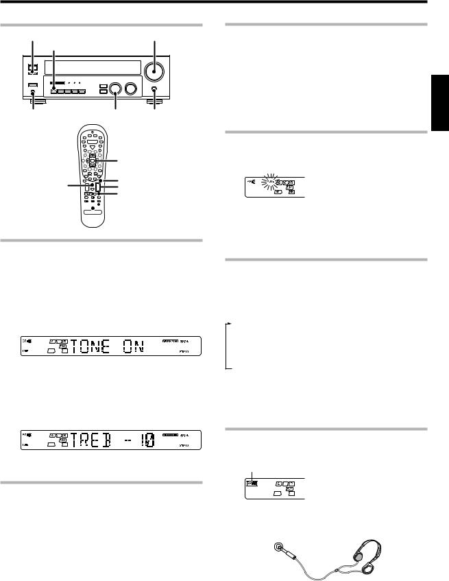
Adjusting the Tone (remote control only)
You can adjust the sound quality when the receiver is in the PCM stereo and analog stereo mode.
1For the remote control, press and hold the TUNER key for more than 3 seconds to switch to receiver mode.
2 Press the Tone key to select the TONE mode.
3Use the MULTI CONTROL knob or Multi %/fikeys to select TONE
ON/OFF.
4When in TONE ON selection, press the Tone key for the following displays.
BASS : Select this to adjust the low frequency range. TREB : Select this to adjust the high frequency range.
5Use the MULTI CONTROL knob or Multi %/fi keys to adjust the sound quality.
•The bass and treble levels are adjustable from -10 to +10 in 2 step increments.
Adjusting the Loudness mode (remote control only)
You can adjust the Loudness function which controls the low volume settings to maintain the music’s richness. The adjustment can be made when the receiver is in the PCM stereo and analog stereo mode.
Press the Loudness key to turn the LOUDNESS setting ON.
To cancel |
ENGLISH |
|
|
Press the Loudness key again so that the “LOUDNESS” indicator |
|
goes off. |
|
Muting the sound
The MUTE key lets you mute the sound of the speakers.
Press the MUTE key.
To cancel
Press the MUTE key again so that the “MUTE” indicator goes off.
•MUTE ON can also be deactivated by turning the volume control knob.
ACTIVE EQ mode
You can enjoy a more impressive sound effect when ACTIVE EQ is turned ON during Dolby Digital and DTS playback and, when in PCM and analog stereo mode.
Press the ACTIVE EQ key for the following selections;
1 |
ACTIVE EQ MUSIC |
: Effective when listening to music. |
|
|
(The ACTIVE EQ LED indicator lights up.) |
2 |
ACTIVE EQ CINEMA : Effective when watching a movie. |
|
|
|
(The ACTIVE EQ LED indicator lights up.) |
3 |
ACTIVE EQ TV |
: Effective when watching TV. |
|
|
(The ACTIVE EQ LED indicator lights up.) |
4 |
ACTIVE EQ OFF |
: The ACTIVE EQ function is turned OFF. |
|
|
(The ACTIVE EQ LED indicator goes off.) |
•ACTIVE EQ function will not be available when REC MODE, AUTO TUNING or PRESET MEMORY is ON and during 96kHz LPCM playback.
Listening with headphones
1Press the SPEAKERS ON/OFF key so that the speaker indicator goes off.
Make sure the SP indicator is turned OFF.
Once-touch low frequency emphasis (Bass Boost) (remote control only)
You can adjust the sound quality when the receiver is in the PCM stereo and analog stereo modes.
Press the Bass Boost key.
•Press the key once to select the maximum (+10) low frequency emphasis setting.
•TONE will automatically be turned ON.
•This key does not function when the receiver is in the sound quality
or ambience effects adjustment mode. |
¢~• |
Switching back the previous setting
Press the Bass Boost key again.
•If you turn off all of the speakers when in surround mode, the surround mode will be canceled as well, resulting in stereo playback.
2 Connect headphones to the PHONES jack.
PHONES
3Use the VOLUME CONTROL knob or VOL +/– keys to adjust the volume.
19 EN
Recording
Recording audio (analog sources)
ENGLISH |
INPUT SELECTOR |
|
Recording a music source
1Use the INPUT SELECTOR knob to select the source (other than “MD/TAPE”) you want to record.
2 Set the MD or TAPE recorder to record.
3 Start playback, then start recording.
Recording video
1Use the INPUT SELECTOR knob to select the video source (other than “VIDEO1”) you want to record.
2Set the video deck connected to VIDEO 1 to record.
• Select the REC MODE to record a digital input source.
3Start playback, then start recording.
• Recording may not be normal for some video software. This is due to
the copy guard condition. °
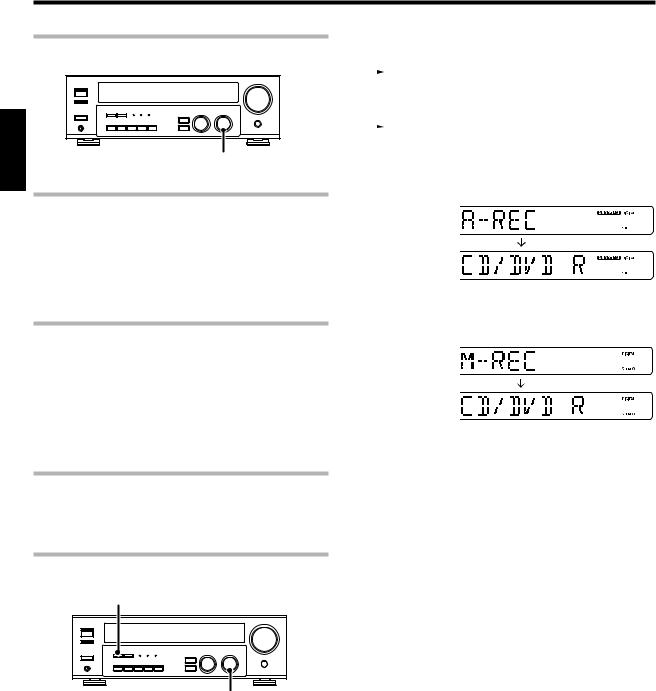
Recording audio (digital sources)
Switch on the REC mode to record a digital input source.
Usually use the A-REC (Auto-Record) mode to record audio input sources. When the digital mode changes during recording in the A-REC mode, the audio input source may be interrupted momentarily.
Recording music in A-REC or M-REC mode
DIMMER
INPUT SELECTOR
1Use the INPUT SELECTOR knob to select the source (CD/DVD, DVD/6CH or VIDEO2) you want to record.
2 Set the MD or TAPE recorder to record.
3Press and hold the DIMMER key for more than 2 seconds to select the A-REC or M-REC mode during digital input.
|
|
1 Rec mode off |
: The digital input record mode is switched off. |
|
|
2 A-REC mode |
: The digital input signals (DTS, Dolby Digital, |
|
|
|
or PCM) are identified automatically and |
|
|
|
converted into stereo signals that are ready |
|
|
|
for recording. |
|
|
3 M-REC mode |
: The input signal type at the moment this |
|
|
||
|
|
|
mode is selected is held throughout this |
|
|
|
mode. |
For A-REC mode: |
|
||
For M-REC mode:
4Start playback, then start recording.
•If the audio reproduction stops in the middle due to change in the input signals, etc., press the DIMMER key.
20 EN
Listening to radio broadcasts
The receiver can store up to 40 stations in the memory and recall them by one-touch operation.
Radio stations can be classified into RDS (Radio Data System) stations and other stations. To listen to or store RDS stations in the preset memory see “Using RDS (Radio Data System)”.
Tuning (non-RDS) radio stations
MULTI CONTROL
BAND
Multi %/ fi
Tune – 1/ + ¡
Auto
AUTO |
INPUT SELECTOR |
TUNER
¢ |
+ |
+ |
Band |
4 |
|
|
+ |
1Use the INPUT SELECTOR knob or TUNER key to select the tuner.
2Use the BAND key to select the desired broadcast band.
Each press switches the band |
“AM” or “FM” indicator |
|
as follows: |
appears in the display |
|
|
||
1 |
FM |
|
2 |
AM |
|
3Use the AUTO key to select the desired tuning method.
Each press switches the tuning method as follows:
 1 AUTO lit (auto tuning)
2 AUTO not lit (manual tuning)
•Normally, set to “AUTO” (auto tuning). If the radio waves are weak and there is a lot of interference, switch to manual tuning. (With manual tuning, stereo broadcasts will be received in monaural.)
4Use the MULTI CONTROL knob or Multi %/ fikeys, or Tune
– 1/ + ¡keys to select the station.
Frequency |
“ST.” lights when |
|
a broadcast is being |
||
display |
||
received in stereo. |
||
|
“TUNED” is displayed when a station is received.
Auto tuning : The next station is tuned automatically.
Manual tuning : Turn the knob (press the key) to select the desired station.
Using RDS (Radio Data System)
RDS is a system that transmits useful information (in the form of digital data) for FM broadcasts along with the broadcast signal. Tuners and receivers designed for RDS reception can extract the information from the broadcast signal for use with various functions, such as automatic display of the station name.
RDS functions: |
|
ENGLISH |
|
PTY (Program TYpe Identification) Search |
£ |
||
|
|||
Automatically tunes to a station that is currently broadcasting the |
|
||
specified program type (genre). |
|
|
|
PS (Program Service Name) Display
Automatically displays the station name transmitted by the RDS station.
RDS AUTO MEMORY function £
Automatically selects and stores up to 40 RDS stations in the preset memory.
If fewer than 40 RDS stations have been stored in the preset memory, regular FM stations will be stored in the remaining places.
Radio Text function
Displays the radio text data transmitted by some RDS stations when you press the RDS Disp. (Display) key. There is “NO RT” display if no text data is transmitted.
The “RDS” indicator lights up when an RDS broadcast (signal) is received.
Note
Some functions and function names may differ for certain countries and areas.
Before using a function utilizing the RDS, be sure to perform the RDS Auto Memory operation by referring to the description in “Presetting RDS stations (RDS AUTO MEMORY)”. £
Presetting radio stations manually
The RDS auto memory function assigns preset numbers to RDS stations starting from preset number “1”. Therefore, be sure to execute the RDS auto memory function before using the following operaptions to manually
store AM stations and other FM stations, and RDS stations. |
|
See “Presetting RDS stations (RDS AUTO MEMORY)”. |
£ |
MEMORY
MULTI CONTROL
1Tune to the station you want to store.
Continued to next page
21 EN
2Press the MEMORY key while receiving the station. |
2Use the P.Call @¥#keys to select the desired station. |
|
Blinks for 5 seconds |
Lights for 5 seconds |
|
Listening to radio broadcasts |
|
|
• Each time you press the key, another preset station is received in order.
Pressing the P.Call # does the following:
ENGLISH |
Proceed to step 3 within 5 seconds. |
3Use the MULTI CONTROL knob or Multi %/ fikeys to select |
|
|
(If more than 5 seconds elapse, press the MEMORY key again). |
|
one of the station presets (1 – 40). |
|
4Press the MEMORY key again to confirm the setting. |
|
• Repeat steps 1, 2, 3, and 4 to store as many stations as |
|
necessary. |
|
• If you store a station at a previously used preset, the previous station |
|
will be replaced by the new one. |
|
Receiving preset stations |
|
TUNER |
|
Numeric keys |
|
¢ + + |
|
4 |
|
+ |
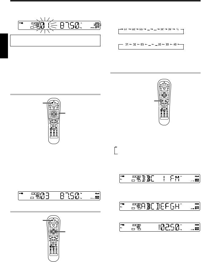
1Press the TUNER key to select tuner as the source.
2Enter the number of the preset station you want to receive (up to “40”).
Press the numeric keys in the following order:
For “15”, press ................................ |
0,5 |
For “20”, press ................................ |
0,0,) |
•If you make a mistake entering a two digit number, press the +10 key repeatedly to return to the original display and start again.
Pressing the P.Call @ does the following:
Holding down the P.Call # or @ key, lets you skip through the presets, receiving each preset station at 0.5 second intervals.
Using the RDS Disp. (Display) key
RDS Disp.
¢ + |
+ |
4
+
Pressing the RDS Disp. key changes the contents of the display.
Each press switches the display mode as follows:
1 PS (Program Service name) display
2 RT (Radio Text) display
3Frequency display
1 PS (Program Service name) display:
The station name is displayed automatically when an RDS broadcast is received.
If no PS data was sent, “NO PS” is displayed.
2RT (Radio Text) display:
Text data accompanying the RDS broadcast scrolls across the display. “NO RT” or “RT----” is displayed if the current RDS station does not provide RT data.
Receiving preset stations in order (P.Call)
|
3 Frequency display: |
TUNER |
Displays the frequency of the current station. |
|
P.Call |
|
@/ # |
¢ + |
+ |
4 |
|
|
+ |
1Press the TUNER key to select tuner as the source.
22 EN

Listening to radio broadcasts
Presetting RDS stations (RDS AUTO MEMORY)
1Press the PTY key to activate the PTY search mode.
This function automatically stores up to 40 RDS stations in the preset memory. In order to use the PTY function, the RDS stations must be stored in the preset memory using the RDS AUTO MEMORY function.
MEMORY
|
|
|
|
|
|
|
|
|
|
|
|
|
|
|
|
|
|
|
|
|
|
|
|
|
|
|
|
|
|
|
|
|
|
|
|
|
|
|
|
|
|
|
|
|
|
|
|
|
|
|
|
|
|
|
|
|
|
|
|
|
|
|
|
|
|
|
|
|
|
|
|
|
|
|
|
|
|
|
|
|
|
|
|
|
|
|
|
|
|
|
|
|
|
|
|
|
|
|
|
|
|
|
|
|
|
|
|
|
|
|
|
|
|
|
|
|
|
|
|
|
|
|
|
|
|
|
|
|
|
BAND |
|
AUTO |
|
INPUT SELECTOR |
|||||||||
|
|||||||||||||||
1Use the INPUT SELECTOR knob to select the tuner.
2Use the BAND key to set the broadcast band to “FM”.
3Press and hold the MEMORY key for more than 2 seconds.
•After a few minutes, up to 40 RDS stations are preset in order from channel “01”.
•Stations already stored in the preset memory may be replaced by RDS stations. (i.e., If the RDS AUTO MEMORY function detects 15 RDS stations, the stations currently preset at numbers 01~15 will be replaced by the RDS stations.)
Tuning by Program TYpe (PTY search)
This function lets you set the tuner to automatically search for stations which are currently broadcasting the type of program (genre) you want to listen to.
Under certain receiving conditions, it may take more than 1 minute to complete the search.
Multi %/ fi
PTY
¢ + |
+ |
4
+
Tune – 1/ + ¡
Preparations
•Execute the RDS auto memory procedure.
•Set the broadcast band to FM.
•Tune to an RDS station.
When an RDS broadcast is received, the program type is shown on |
|
|
the display. If no PTY data is available, or if the station is not an RDS |
ENGLISH |
|
station, “NONE” is displayed. |
||
|
||
2While the “PTY” indicator is lit, use the MULTI CONTROL |
|
|
knob or Multi %/ fikeys, or Tune – 1/ + ¡keys to select |
|
|
the program type of your choice. |
|
Program type table
Program Type Name |
Display |
Program Type Name |
Display |
Pop Music |
POP M |
Weather |
WEATHER |
Rock Music |
ROCK M |
Finance |
FINANCE |
Easy Music |
EASY M |
Children’s Program |
CHILDREN |
Light Classical Music |
LIGHT M |
Social Affairs |
SOCIAL |
Serious Classical Music |
CLASSICS |
Religion |
RELIGION |
Other Music |
OTHER M |
Phone In |
PHONE IN |
News |
NEWS |
Travel |
TRAVEL |
Current Affairs |
AFFAIRS |
Leisure |
LEISURE |
Information |
INFO |
Jazz Music |
JAZZ |
Sport |
SPORT |
Country Music |
COUNTRY |
Education |
EDUCATE |
National Music |
NATION M |
Drama |
DRAMA |
Oldies Music |
OLDIES |
Culture |
CULTURE |
Folk Music |
FOLK M |
Science |
SCIENCE |
Documentary |
DOCUMENT |
Varied Speech |
VARIED |
|
|
“NO PROG” is displayed if this operation is attempted before performing the RDS Auto Memory operation.
3Press the PTY key to start searching.
EXAMPLE: Searching for a Rock Music broadcast.
Display while searching.
Blinks |
Program type name display |
Display when a station is received.
Goes out
Station name display
•No sound is heard while “PTY” is blinking.
•If the desired program type cannot be found, “NO PROG” is displayed, then after several seconds the display returns to the original display.
To select another program type
Repeat steps 1, 2 and 3.
23 EN
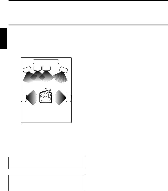
Ambience effects
This receiver is equipped with listening modes that allow you to enjoy an enhanced sonic ambience with a variety of video sources.
In order to obtain the optimum effect from the surround modes, make sure to input the proper speaker settings beforehand.
%
Surround modes
ENGLISH
The below speaker placements are for 5.1 channel surround sound system which are;
•Dolby Digital
•Dolby Pro Logic II
•DTS
•DSP
•DVD 6-channel
The below speaker placements are for 6.1 channel surround sound system which is;
•Dolby Digital EX
•Dolby Digital, Dolby Pro Logic II and DSP if “SURR MIX ON”.
^
|
TV / SCREEN |
|
|
L |
SW |
C |
R |
|
|
||
SL |
SR |
No Surround Back speaker
|
TV / SCREEN |
|
|
L |
SW |
C |
R |
|
|
||
SL |
SR |
SB
With Surround Back speaker
L |
Front left speaker |
SL |
Surround left speaker |
SW |
Subwoofer |
SR |
Surround right speaker |
C |
Center speaker |
SB |
Surround back speaker |
R |
Front right speaker |
|
|
|
|
|
|
Manufactured under license from Dolby Laboratories. “Dolby”, “Pro Logic” and the double-D symbol are trademarks of Dolby Laboratories.
Note
LFE = Low Frequency Effects. This channel delivers separate nondirectional bass signals to the subwoofer for more dynamic deep bass sound effects.
“DTS” and “DTS Digital Surround” are registered trademarks of Digital Theater Systems, Inc.
24 EN

Ambience effects
Dolby Digital
The Dolby Digital surround format lets you enjoy up to 5.1 channels of digital surround sound from Dolby Digital program sources (such
as Laserdisc or DVD software marked 
 ). Compared with previous Dolby surround, Dolby Digital provides even better sound quality, greater spatial accuracy, and improved dynamic range.
Although a full set of speakers (front left, right, and center, surround left and right, and a subwoofer) is required for true 5.1 channel Dolby Digital surround sound, this receiver lets you enjoy Dolby Digital (and Dolby Surround) program sources, even if you connect only the front speakers.
Dolby Digital EX
Dolby Digital EX is an extension of Dolby Digital technology, Dolby Digital EX creates six full-bandwidth output channels from 6.1- channel sources. This is done using a matrix decoder that derives three surround channels from the two in the original recording.
This is achieved by using three different surround signals, surround left, surround right, and surround back, each driving its own array of speakers. Think of it as adding a center channel for the rear speakers, which give more diffuse and natural surround effect, even if you wanted the ability to completely encircle the audience with sound, positioning sound effects exactly where they would be heard in real life. For best results, Dolby Digital EX should be used with movie soundtracks recorded with Dolby Digital Surround EX which contain a digital flag that will automatically activate this feature. However, for titles released prior to late 2001, this feature has to be activated manually.
Although a full set of speakers (front left, right, and center, surround left and right, surround back and a subwoofer) is required for true 6.1 channel Dolby Digital Surround EX sound, this receiver lets you enjoy Dolby Digital (and Dolby Surround) program sources, even if you connect only the front speakers.
Although only Dolby Digital soundtracks incorporate a separate low frequency channel, connecting a subwoofer will also improve deep bass performance in the other surround modes.
The indication “LFE” appears in the display when a signal is being input for this channel. ¢
DTS mode
The DTS multi-channel audio format is available on CD, LD and DVD software. DTS is a strictly digital format and cannot be decoded inside most CD, LD or DVD players. For this reason, if you attempt to listen to DTS encoded software through the analog output of your new CD, LD or DVD player, you will experience digital noise in most cases. This noise can be quite loud if the analog output is connected directly to a high power amplification system. Proper measures for playing the digital output as described below should be taken to avoid this situation. To enjoy DTS Digital Surround playback, an external 5.1 channel DTS Digital Surround decoder system or an amplifier with a built-in DTS Digital Surround decoder must be connected to the digital output (S/P DIF, AES/EBU or TosLink) of a CD, LD or DVD player.
All models are incorporated with the DTS decoder.
DTS has a .1 or LFE channel.
The indication “LFE” appears in the display when a signal is being input for this channel. ¢
DSP mode
The DSP mode lets you add the atmosphere of a live concert or hall to almost any type of program source. These modes are particularly effective when used with stereo program sources, like CD, television, and FM radio. You might enjoy trying the ARENA, JAZZ CLUB, THEATER, STADIUM or DISCO mode the next time you watch a concert or sporting event!
What's DSP?
DSP stands for Digital Signal Processor.
The way a sound is heard in an actual environment depends on a variety of different factors. One of the most important is reverberation (the act of decaying elements of sound echoing in various places). The DSP modes produce the feeling of presence by using the DSP to create reverberation, without spoiling the sound quality of the original signal.
Dolby PRO LOGIC II
Dolby Pro Logic II was designed specifically to provide a new sense of spatiality, directionality and articulation of sounds from Dolby Surround encoded sources (such as video and Laserdisc software marked 
 ). This is achieved with an intelligent, built-in feedback logic design, a matrix surround decoding and the decoding of stereo, full bandwidth surround outputs. The PRO LOGIC II modes programmed into this receiver are “MOVIE”, “MUSIC” and “PRO LOGIC”. The “MOVIE” mode of the PRO LOGIC II has preset characteristics to produce a calibrated, high-level surround sound playback while the “MUSIC” mode has user-adjustable characteristics to offer the three optional controls, like “Dimension”, “Center Width” and “Panorama” modes to allow optimization of the soundfields as desired. The “Dimension” control allows the user to gradually adjust the soundfield either towards the front or towards the rear; the “Center Width” control allows various adjustment of the left-center-right speakers’ balance; the “Panorama” mode extends the front stereo image to include the surround speakers for an exciting “wraparound” effect with side wall imaging.
DVD 6-channel mode
Using a DVD player or the like equipped with six (5.1) output channels and the receiver, you can enjoy multi-channel encoded DVD source material in all its splendor. Since the source signals are digital and each channel is input independently, the resulting sound quality, sense of spaciousness, and dynamic range are superb.
The indication “LFE” appears in the display during DVD 6-channel mode selection. ¢
ENGLISH
25 EN

Ambience effects
Surround play
The DTS compatible models can reproduce a CD, DVD, or LD carrying the DTS mark.
DOLBY DIGITAL can be used when playing DVD or LD software bearing the  mark and DOLBY DIGITAL format digital broadcasts (etc.). DOLBY PRO LOGIC can be used when playing video, DVD, or LD software bearing the

 mark.
mark.
ENGLISH |
|
|
LISTEN MODE |
||||||||||
|
|
|
|||||||||||
|
|
|
|
|
|
|
|
|
|
|
|
|
|
|
|
|
|
|
|
|
|
|
|
|
|
|
|
|
|
|
|
|
|
|
|
|
|
|
|
|
|
|
|
|
|
|
|
|
|
|
|
|
|
|
|
|
|
|
|
|
|
|
|
|
|
|
|
|
|
|
|
|
|
|
|
|
|
|
|
|
|
|
|
|
|
|
|
|
|
|
|
|
|
|
|
|
|
|
|
|
|
|
|
|
|
|
|
|
|
|
|
|
|
|
|
|
|
|
|
|
|
|
|
|
|
INPUT MODE |
INPUT SELECTOR |
Input
Selector
¢ + |
+ |
4
+
Input Mode Listen Mode
Preparations
•Turn ON related components.
•Complete “Preparing for surround sound” (speaker settings).%
•Use the INPUT SELECTOR to select the component you wish to play back with surround sound.
•Use the INPUT MODE key to select the input mode (analog or
digital) for the source you wish to playback. |
8 |
•Noise will be produced when a DTS source is played by selecting the analog input.
1Start playing the video software.
2Press the LISTEN MODE key to select the listening mode.
The listening mode settings are stored separately for each input. If the input mode is set to full auto (“AUTO DETECT” lights), the receiver selects the optimal listening mode automatically based on the type of input signal and the speaker settings.
Each press of the LISTEN MODE key switches the setting as listed.
The listening mode settings are different depending on the type of input signal.
When the DOLBY DIGITAL or DOLBY DIGITAL EX signal is input:
(The DOLBY DIGITAL or PRO LOGIC indicator lights up.)
1 DOLBY DIGITAL |
: DOLBY DIGITAL surround. |
2 DOLBY DIGITAL EX : DOLBY DIGITAL EX surround. |
|
|
(The DOLBY DIGITAL EX LED indicator lights |
|
up.) |
3 PL II MOVIE |
: PRO LOGIC II surround MOVIE mode. |
|
(The PRO LOGIC indicator lights up.) |
4 PL II MUSIC |
: PRO LOGIC II surround MUSIC mode. |
|
(The PRO LOGIC indicator lights up.) |
5 PRO LOGIC |
: PRO LOGIC II surround PRO LOGIC mode. |
|
(The PRO LOGIC indicator lights up.) |
6 STEREO |
: Normal stereo playback. |
|
(The STEREO indicator lights up.) |
When you select DOLBY DIGITAL
“DOLBY DIGITAL” will scroll from right to left.
When the DTS signal is input:
(The DTS LED indicator lights up.)
1 DTS |
: DTS surround |
2 STEREO |
: Normal stereo playback |
When the analog signal or the digital signal (except for DOLBY DIGITAL or DTS signal) is input:
1 PL II MOVIE : PRO LOGIC II surround MOVIE mode.
|
(The PRO LOGIC indicator lights up.) |
2 PL II MUSIC : PRO LOGIC II surround MUSIC mode. |
|
|
(The PRO LOGIC indicator lights up.) |
3 PRO LOGIC |
: PRO LOGIC II surround PRO LOGIC mode. |
|
(The PRO LOGIC indicator lights up.) |
4 ARENA |
: DSP Surround ARENA mode. |
5 JAZZ CLUB |
: DSP Surround JAZZ CLUB mode. |
6 THEATER |
: DSP Surround THEATER mode. |
7 STADIUM |
: DSP Surround STADIUM mode. |
8 DISCO |
: DSP Surround DISCO mode. |
9 STEREO |
: Normal stereo playback. |
|
(The STEREO indicator lights up.) |
•Dolby Digital or DTS signal having more channels than the maximum number of playback channels available using the receiver’s current settings is input, downmixing is performed to match the number of available channels.
3Adjust the volume.
Notes
•Depending on the type of the signal or speaker setting, some listening modes cannot be selected.
•When playback is started, the sound may be cut or interrupted before the input source is confirmed as Dolby Digital.
•To enjoy Dolby Digital surround (as well as all the other listening modes) from a single component, be sure to use a Dolby Digital compatible source component.
26 EN
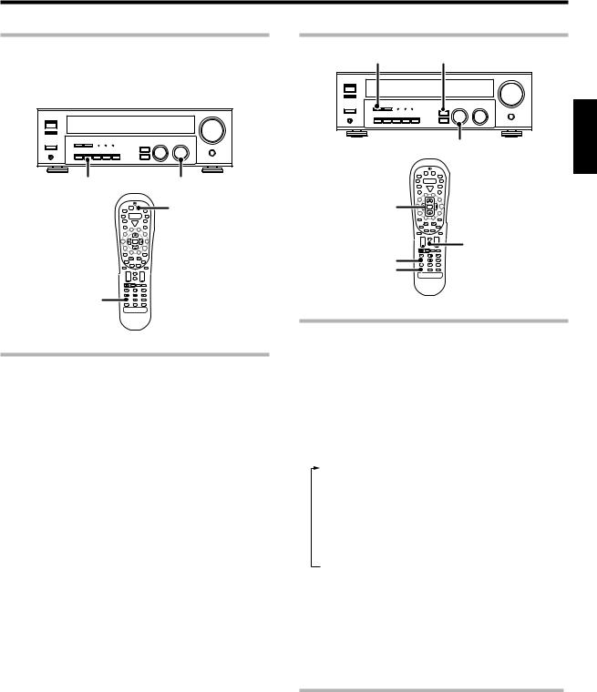
Ambience effects
DVD 6-channel playback
Using a DVD player or the like equipped with six (5.1) output channels and the receiver, you can enjoy surround sound playback.
Connecting a DVD player which can decode the surround signal itself is also acceptable.
INPUT MODE |
INPUT SELECTOR |
DVD/6CH
¢ + |
+ |
4
+
Input Mode
Preparations
•Connect your DVD player to the DVD/6CH jacks of the receiver.
•Turn on all other components that will be used.
• Complete “Preparing for surround sound”. |
% |
1Select “DVD/6CH” as the input source.
2Select "6CH INPT" by pressing the INPUT MODE key.
3Start playback of the DVD software.
4Adjust the volume.
•It is not possible to adjust the volume level or sound quality (SETUP,
SOUND, LISTEN MODE, ACTIVE EQ and Tone keys will not be functional) of the channels separately when the receiver is in the 6CH INPUT mode. Adjust the volume with the controls of the DVD player.
For the powered subwoofer, you can adjust the volume of the subwoofer using the subwoofer’s own volume control.
Convenient functions
DIMMER SOUND
MULTI CONTROL |
ENGLISH |
|
Multi %/ fi
¢ |
+ |
+ |
4 |
|
Sound |
|
|
+ |
Dimmer
Listen Mode
Adjusting the sound
You can make further adjustments to the sound while listening to playback in the surround mode.
1For the remote control, press and hold the TUNER key for more than 3 seconds to switch to receiver mode.
2Press the SOUND key until the desired item appears in the display.
Each time you press the button, the menu changes as follows: Note that some items are not displayed in certain modes.
1 C (center speaker level adjustment)*
2 SR (right surround speaker level adjustment)*
3 SB (surround back speaker level adjustment)*
4 SL (left surround speaker level adjustment)*
5 SW (subwoofer level adjustment)*
6 INPUT (input level adjustment - analog mode only) & 7 NIGHT (midnight mode ON/OFF - Dolby Digital mode only) 8 PANORAMA (panorama mode ON/OFF)**
9 DIMENSION (dimension adjustment)**
0CENTER WIDTH (center width adjustment)**
*The adjustment is only temporary for the current input selection. The value will return automatically to the original setup value
when the power is turned on/off or when the input selection is changed.
** Pro Logic II Music mode only.
3Use the MULTI CONTROL knob or Multi %/fikeys to adjust the setting as desired.
Midnight mode (Dolby Digital mode only)
When watching movies at night, you might not be able to raise the volume as loud as normal. Midnight mode compresses the dynamic range of previously specified heavy sound passage of the Dolby Digital sound track (like scenes with sudden increases in volume) to minimize the difference in volume between the scenes with heavy sound passage and scenes with normal sound passage. This makes it easy to hear all of the sound track, even when listening at low volumes.
Continued to next page
27 EN

ENGLISH
Ambience effects
1Press the SOUND key repeatedly until “NIGHT” appears on the display.
•This can be selected only if CD/DVD, DVD/6CH or VIDEO2 is selected as the source and the listen mode is set to “DOLBY DIGITAL.”
2Use the MULTI CONTROL knob or Multi %/fikeys to select the
ON or OFF setting.
•Some Dolby Digital software may not be compatible with the Midnight mode.
Panorama mode (Pro Logic II Music mode only)
When listening to music, you will be able to enjoy the “wraparound” sound effect when you adjust the panorama mode.
1Press the SOUND key repeatedly until “PANORAMA” appears on the display.
•The PANORAMA setting indication scrolls across the display. “PANORAMA” will be scrolled from right to left.
Center Width mode (Pro Logic II Music mode only)
Center Width adjustment allows you to enjoy an enhanced sound when listening to music through center image from only center speaker, or left and right speakers or various combinations adjustments.
1Press the SOUND key repeatedly until “CENTER WIDTH” appears on the display.
•The CENTER WIDTH indication scrolls across the display.
•When the center speaker is switched OFF, this mode will not be effective.
2Use the MULTI CONTROL knob or Multi %/ fikeys to adjust the left-center-right output.
Center image will be heard from center speaker only.
Center image will be heard from left and right speakers only.
•When in other positions, center image from center speaker, left and right speakers can be heard simultaneously with various combinations.
2Use the MULTI CONTROL knob or Multi %/fi keys to select
PANORAMA ON or OFF.
1 ON : PANORAMA mode is ON.
2 OFF : PANORAMA mode is OFF.
Display dimmer adjustment
The dimmer function lets you select the brightness of the receiver's display. You might find this useful if you darken your room to watch movies or listen to music.
Each time you press the DIMMER key, the display brightness changes among the three available settings. Select the brightness level you find most pleasing.
Dimension mode (Pro Logic II Music mode only)
When listening to music with certain recordings, you will also be able to achieve a suitable balance from all the speakers by adjusting the dimension mode.
1Press the SOUND key repeatedly until “DIMENSION” appears on the display.
• The DIMENSION indication scrolls across the display.
2Use the MULTI CONTROL knob or Multi %/fikeys to adjust the soundfield towards the rear or the front.
Soundfield is adjusted towards the front.
Soundfield is in neutral position.
Soundfield is adjusted towards the rear.
96kHz LPCM playback
The receiver is compatible with the 96kHz LPCM playback. To play a 96kHz DVD, set the listen mode to “STEREO”.
•In F-AUTO input mode, the listen mode will automatically be STEREO.
•When in D-MANUAL input mode (listen mode is not STEREO), “FS 96kHz” will appear in the display and no sound can be heard from the speakers.
Press the LISTEN MODE key (the listen mode changes to the STEREO mode) to output sound from the speakers.
28 EN
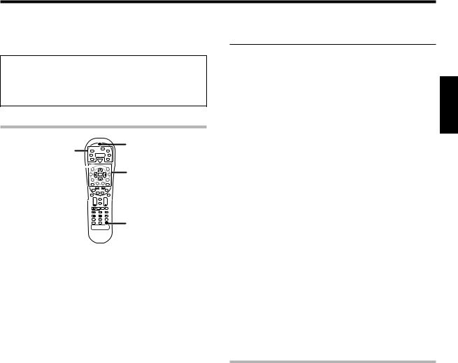
Basic remote control operations for other components
The remote control supplied with this receiver is also capable of controlling components from a variety of manufacturers once you register the appropriate setup codes into the remote control unit.
Low battery warning
Replace all two batteries with new ones when you notice a shortening of the distance from which the remote control will operate. The remote control is designed to retain setup codes in memory while you change batteries.
Registering setup codes for other components

 LED Source
keys
SRC Power 

Numeric keys
¢ + +
4
+
Remote
Setup
1Find the setup code of the component to be registered.
• Refer to the setup code lists to find the setup code for the
component to be registered. |
|
⁄ |
||||||
Example: To register a DVD made by KENWOOD, you would enter |
||||||||
“0534”. |
|
|
|
|
|
|
|
|
|
|
|
|
|
|
|
|
|
Input |
|
Component |
Maker |
|
Code |
Key |
||
|
|
|
|
|
|
|
|
|
(DVD) |
|
DVD player |
KENWOOD |
|
0534 |
DVD/6CH |
||
|
|
|
|
|
|
|
||
|
|
|
|
|
|
|
|
|
|
|
|
|
|
||||
Source key |
|
|
Other components |
|
||||
|
|
|
|
|
|
|||
TUNER |
|
|
Receiver (Kenwood) |
|
|
|||
|
|
|
|
|
||||
DVD/6CH |
|
|
DVD (other manufacturers’) |
|
||||
|
|
|
|
|
|
|||
CD/DVD |
|
|
CD and MD (Kenwood) |
|
|
|||
|
|
|
|
|
||||
MD/TAPE |
|
|
Cassette deck (Kenwood) |
|
||||
|
|
|
|
|||||
VID1 |
|
|
VCR and PVR (other manufacturers’) |
|||||
|
|
|
|
|||||
VID2 |
|
|
Cable and DTV decoder (other manufacturers’) |
|||||
|
|
|
|
|
||||
PHONO |
|
|
Additional key for re-assigning |
|
||||
|
|
|
|
|||||
TV |
|
|
TV/VCR combo, TV/DVD combo, TV (other |
|||||
|
|
|
|
manufacturers’) |
|
|
||
2Press the Source (PHONO, VID2, VID1, DVD/6CH, CD/DVD, |
||||||||
MD/TAPE) keys. |
|
|
|
|
7 |
|||
• PHONO key has to be re-assigned to another key before a setup code can be registered. º
• While in Tuner mode, setup code function will not be available.
3Press and hold the Remote Setup key until the LED blinks twice, then release the Remote Setup key.
4Press the numeric key to enter the four-digit code for the component to be registered.
•If performend correctly, the LED will blink twice.
•Point the remote control at the component and press SRC (source) Power key once. It should turn on or off. If it does not respond repeat steps 2 to 4.
•If the component still does not work, try searching for the code.
5Repeat steps 2to 4to register additional components until all components have been registered.
Note |
|
Although each setup code is designed to work with a number of |
|
different models, certain codes may not work with some models. |
|
(Also, certain codes may only operate some of the functions available |
|
on a given model.) |
ENGLISH |
If your component does not respond after trying all the codes listed for |
|
Searching for your code |
|
your component, or if your component is not listed at all, try searching for |
|
your code. |
|
For example, to search for a code for your TV. |
|
1Press the TV key once. Next, press and hold the Remote Setup key until the LED blinks twice, then release the Remote Setup key.
2Press the numeric key to enter “9 - 9 - 1”.
•The LED will blink twice.
3Point the remote control at the TV and slowly alternate between pressing the SRC (source) Power and TV keys.
•Stop when the TV turns on or off.
•In the search mode, the remote control will send IR codes from its library to the selected device, starting with the most popular code first.
4Press the Remote Setup key once to lock in the code.
5To search for the codes of your other components, repeat steps 1 through 4, but substitute the appropriate key (i.e.,
PHONO, VID2, VID1, DVD/6CH, CD/DVD, MD/TAPE) for the component you are searching for.
• PHONO key has to be re-assigned to another key before a setup code can be registered. º
Checking the codes
If you have set up the remote control using the procedures described in “Searching for your codes”, you may need to find out which four-digit code is operating your equipment:
For example, to find out which code is operating your TV:
1Press the TV key once. Next, press and hold the Remote Setup key until the LED blinks twice, then release the Remote Setup key.
2Press the numeric key to enter “9 - 9 - 0”.
•The LED will blink twice.
3To view the code for the first digit, press “1”once. Wait for 3 seconds, count the number of times the LED blinks (e.g., blinks = 3) and write down that number.
• If a code digit is “0”, the LED will not blink.
4Repeat step 3 three more times for the remaining digit. Use
“2” for the second digit, “3” for the third digit, and “4” for the fourth digit.
5To check the codes of your other components, repeat steps 1 through 4, but substitute the appropriate key (i.e., PHONO,
VID2, VID1, DVD/6CH, CD/DVD, MD/TAPE) for the component you are checking.
•As suggested earlier on, write down each of the four-digit code.
•PHONO key has to be re-assigned to another key before a setup
code can be registered. |
º |
29 EN
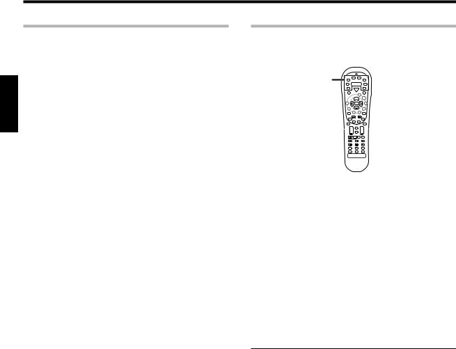
Basic remote control operations for other components
ENGLISH
Re-assigning device keys
The remote control can be set up to control a second TV or VCR, or any combination of eight home entertainment components.
For example, to control the operation of two different VCR using the remote control, the user need to re-assign the unused VID2 key to operate the second VCR (VID1) as follows:
1Press and hold the Remote Setup key until the LED blinks twice, then release the Remote Setup key.
2Press the numeric key to enter “9 - 9 - 2”.
•The LED will blink twice.
3Press the VID1 key once, then press the VID2 key once.
•The user now can operate VID2 as a second VCR along with VID1.
• Refer to the table in the previous page for the combination of source keys and the other components assignment. ª
4To re-assign other device keys, repeat steps 1through 3by substituting the key sequence from the chart below for the most popular components:
To re-assign key
Sequence |
Perform |
|
|
TV as 2nd VID1 key |
Remote Setup -9 -9 -2 |
-VID1 - TV |
|
TV as 2nd VID2 key |
Remote Setup -9 -9 -2 |
-VID2 - TV |
|
TV as 2nd CD/DVD key |
Remote Setup -9 -9 -2 |
-CD/DVD - TV |
|
TV back to TV key |
Remote Setup -9 -9 -2 |
-TV - TV |
|
VID1 as 2nd TV key |
Remote Setup -9 -9 -2 |
-TV - VID1 |
|
VID1 as 2nd VID2 key |
Remote Setup -9 -9 |
-2 |
-VID2 - VID1 |
VID1 as 2nd CD/DVD key |
Remote Setup -9 -9 |
-2 |
-CD/DVD - VID1 |
VID1 back to VID1 key |
Remote Setup -9 -9 |
-2 |
-VID1 - VID1 |
5To clear the re-assignment and reset the remote control to its original operation mode:
1Press and hold the Remote Setup key until the LED blinks twice, then release the Remote Setup key.
2 Press the numeric key to enter “9 - 9 - 2”.
3 Press the VID2 key twice.
•When a re-assignment is done, the LED will blink twice to confirm your choice. At that time, you will need to program the remote control in order to control the new component.
•If an invalid key sequence is entered, the LED blink once and return to normal operation.
•When in Tuner mode, re-assignment is not available.
Operating other components
This operation lets you operate the registered components. KENWOOD audio components with system control turn on and off automatically with the receiver via the system control connections.
Source
keys
SRC Power

¢ + |
+ |
4
+
1Use the Source keys to select the component you desire.
• Pressing the Source keys also changes the input selector on the
receiver. |
7 |
•WhenyouoperateyourregisteredDVDplayer,CDplayer,Cassette deck, MD player, Cable, DTV decoders, VCR or TV, go to step 2.
•When you operate the CD player, Cassette deck, MD player, or Tuner with system control connection, go to step 3.
2Press the SRC (source) Power key.
•To return to the receiver operation mode, press the TUNER key for more than 3 seconds.
3Press the operation keys you desire. |
fi |
The remote control mode remains at the selected input. If you wish to operate another component, repeat step 2 or 3.
Note
•Be sure to point the remote control at the remote sensor on the receiver when you want to operate KENWOOD components connected by system control cords. Otherwise, point the remote control at the component you want to operate.
•To initialize the remote control, press the Remote Setup key until the LED blinks twice. Then press the numeric key to enter “9-8-1”. The LED blinks twice.
30 EN
 Loading...