


AUDIO VIDEO SURROUND RECEIVER
KRF-V7010 KRF-V6010 KRF-V5010
INSTRUCTION MANUAL
Preparation
KENWOOD CORPORATION
This instruction manual is for some models.
Model availability and features (functions) may differ depending on the country and sales area.
About the supplied remote control (RC-R0507) . . .
Compared to standard remote controls, the remote control supplied with this receiver has several operation modes. These modes enable the remote control to control other audio/video components. In order to effectively use the remote control it is important to read the operating instructions and obtain a proper understanding of the remote control and how to switch its operation modes (etc.).
Using the remote control without completely understanding its design and how to switch the operation modes may result in incorrect operations.
B60-3609-00 00 CS MA (T, E2, Q) ID
Operations
Other
Remote Control
99/12 11 10 9 8 7 6 5 4 3 2 1 98/12 11 10 9 8 7 6 5 4 3 2
Getting started
Before applying the power
2
Units are designed for operation as follows.
U.K. and Europe ............................................... |
AC 230 V only |
Russia ............................................................... |
AC 220 V only |
|
For the United Kingdom |
|
|
Preparations |
2. The fuse cover must be refitted when replacing the fuse in the |
||
|
Factory fitted moulded mains plug |
||
|
1. The mains plug contains a fuse. For replacement, use only a 13- |
||
|
Amp ASTA-approved (BS1362) fuse. |
||
|
moulded plug. |
|
|
|
3. Do not cut off the mains plug from this equipment. If the plug fitted |
||
|
is not suitable for the power points in your home or the cable is too |
||
|
short to reach a power point, then obtain an appropriate safety |
||
|
approved extension lead or adapter, or consult your dealer. |
||
|
If nonetheless the mains plug is cut off, remove the fuse and |
||
|
dispose of the plug immediately, to avoid a possible shock hazard |
||
|
by inadvertent connection to the mains supply. |
||
|
|
IMPORTANT |
|
|
The wires in the mains lead are coloured in accordance with the |
||
|
following code: |
Blue |
: Neutral |
|
|
Brown |
: Live |
|
Do not connect those leads to the earth terminal of a three-pin |
||
|
plug. |
|
|
|
|
|
|
REQUIREMENT BY NEDERLAND GAZETTE
Batteries are supplied with this product. When they empty, you should not throw away. Instead, hand them in as small chemical waste.
Safety precautions
WARNING :
TO PREVENT FIRE OR ELECTRIC SHOCK, DO NOT EXPOSE THIS APPLIANCE TO RAIN OR MOISTURE.
CAUTION
RISK OF ELECTRIC SHOCK
DO NOT OPEN
CAUTION: TO REDUCE THE RISK OF ELECTRIC SHOCK, DO NOT REMOVE COVER (OR BACK). NO USER-SERVICEABLE PARTS INSIDE, REFER SERVICING TO QUALIFIED SERVICE PERSONNEL.
THE LIGHTNING FLASH WITH ARROWHEAD SYMBOL, WITHIN AN EQUILATERAL TRIANGLE, IS INTENDED TO ALERT THE USER TO THE PRESENCE OF UNINSULATED “DANGEROUS VOLTAGE” WITHIN THE PRODUCT’S ENCLOSURE THAT MAY BE OF SUFFICIENT MAGNITUDE TO CONSTITUTE A RISK OF ELECTRIC SHOCK TO PERSONS.
THE EXCLAMATION POINT WITHIN AN EQUILATERAL TRIANGLE IS INTENDED TO ALERT THE USER TO THE PRESENCE OF IMPORTANT OPERATING AND MAINTENANCE (SERVICING) INSTRUCTIONS IN THE LITERATURE ACCOMPANYING THE APPLIANCE.
Caution : Read this page carefully to ensure safe operation.
KRF-V7010/V6010/V5010 (En/T)
Unpacking
Unpack the unit carefully and make sure that all accessories are put aside so they will not be lost.
Examine the unit for any possibility of shipping damage. If your unit is damaged or fails to operate, notify your dealer immediately. If your unit was shipped to you directly, notify the shipping company without delay. Only the consignee (the person or company receiving the unit) can file a claim against the carrier for shipping damage.
We recommend that you retain the original carton and packing materials for use should you transport or ship the unit in the future.
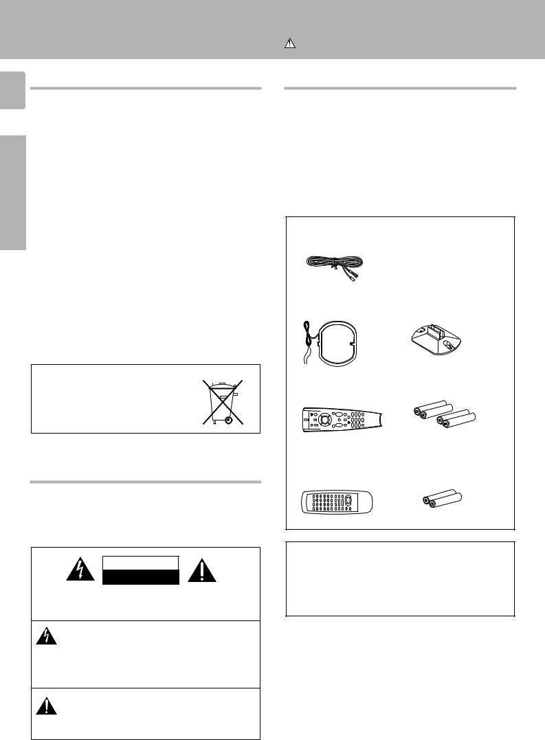
Accessories
FM indoor antenna (1)
AM loop antenna (1) |
Loop antenna stand (1) |
For KRF-V7010 |
|
Remote control unit (1) |
Batteries (R03/AAA) (4) |
RC-R0507 |
|
For KRF-V6010, KRF-V5010 |
|
Remote control unit (1) |
Batteries (R06/AA) (2) |
RC-R0307 |
|
Cleaning
Do not use volatile solvents such as alcohol, paint thinner, gasoline, or benzine, etc. to clean the cabinet. Use a clean dry cloth.
Do not use contact cleaners because it could cause a malfunction. Be specially careful against contact cleaners containing oil, for they may deform the plastic components.

Getting started
KRF-V7010/V6010/V5010 (En/T)
Contents
3
Caution : Read the pages marked  carefully to ensure safe operation.
|
Getting started ................................... |
2 |
|
Before applying the power .................................. |
2 |
|
Safety precautions ............................................... |
2 |
|
Unpacking ............................................................ |
2 |
|
How to use this manual ........................................ |
4 |
|
Special features ................................................... |
4 |
|
Names and functions of parts ................. |
5 |
|
Setting up the system ........................... |
8 |
Preparations |
Connecting audio components ........................... |
8 |
|
Connecting video components ............................ |
9 |
|
Connecting DVD 6-channel jack ......................... |
9 |
|
Connecting the antennas ..................................... |
9 |
|
Connecting the system control .......................... |
10 |
|
Connecting the speakers ................................... |
11 |
|
Preparing the remote control (RC-R0507) ......... |
12 |
|
Preparing the remote control (RC-R0307) ......... |
13 |
|
Preparing for surround sound ................ |
13 |
|
Speaker settings ................................................ |
13 |
Preparations
|
Normal playback ...................... |
14 |
|
Preparing for playback ...................................... |
14 |
|
Listening to a source component ...................... |
15 |
|
Adjusting the sound ........................................... |
15 |
|
Recording ........................................ |
16 |
|
Recording audio ................................................. |
16 |
|
Recording video ................................................. |
16 |
|
Listening to radio broadcasts ................. |
17 |
|
Tuning (non-RDS) radio stations ....................... |
17 |
|
Using RDS (Radio Data System) ....................... |
17 |
|
Using the DISPLAY key ...................................... |
18 |
Operations |
|
|
|
Presetting RDS stations |
|
|
(RDS AUTO MEMORY) ...................................... |
18 |
|
Presetting radio stations manually..................... |
19 |
|
Receiving preset stations .................................. |
19 |
|
Receiving preset stations in order (P.CALL) ..... |
19 |
|
Tuning by program type (PTY search) .............. |
20 |
|
Reserving the desired information ..................... |
20 |
|
Ambience effects ............................... |
22 |
|
Surround modes ................................................. |
22 |
|
Surround play ..................................................... |
23 |
|
DVD 6-channel playback ................................... |
23 |
|
Convenient functions ......................................... |
24 |
|
In case of difficulty ............................. |
25 |
Other |
|
|
|
Specifications ................................... |
27 |
Operations
Other
Remote
Control (Speparete booklet) (RC-R0507)
Quick start guide ................................. |
1 |
Getting the most from |
|
your remote control ............................. |
3 |
Setup code chart ................................. |
7 |
In case of difficulty ............................. |
13 |
Remote operation of other components .... |
14 |
Remote Control

4
Preparations
How to use this manual
The manual covers the KRF-V7010, KRF-V6010, and KRF-V5010. Items such as functions, number of jacks, and remote control details differ somewhat between these models. To confirm the functions available on the model you have purchased, refer to the table below.
Model name |
Remote control |
|
Terminal |
|
|
|
Speaker out |
|
Preout |
|
|
|
|
|
KRF-V7010 |
RC-R0507 |
2 systems |
|
CENTER, SURROUND, |
|
|
(A, B) |
|
SUBWOOFER |
|
|
|
|
|
KRF-V6010 |
RC-R0307 |
2 systems |
|
CENTER, SURROUND, |
|
|
(A, B) |
|
SUBWOOFER |
|
|
|
|
|
KRF-V5010 |
RC-R0307 |
1 system |
|
SUBWOOFER |
|
|
|
|
|
This manual is divided in to four sections, Preparations, Operations, Other, and Remote Control.
Preparations
Shows you how to connect your audio and video components to the receiver and prepare the surround processor.
We've tried to make setting up your system as easy as possible. However, since this receiver works with all of your audio and video components, connecting the system can be fairly complex.
Operations
Shows you how to operate the various functions available from the receiver.
Other
Shows you additional information such as “In case of difficulty” (troubleshooting) and “Specifications.”
Remote Control (Separate booklet) (RC-R0507 only)
Includes the “Quick Start Guide,” which shows you how to operate other components using the remote control, as well as a detailed explanation of all remote control operations. Once you have registered your components with the proper setup codes, you’ll be able to operate both this receiver and your other AV components (TV, VCR, LD player, CD player, etc.) using the remote control supplied with this receiver.
Getting started
KRF-V7010/V6010/V5010 (En/T)
Special features
True home theater sound
This receiver incorporates a wide variety of surround modes to bring you maximum enjoyment from your video software. Select a surround mode according to your equipment or the software you are going to play and enjoy! ™
Dolby Pro Logic & Dolby 3 Stereo
This surround system reproduces theater-like surround sound from video software marked 
 .
.
The PRO LOGIC mode uses the built-in adaptive matrix circuit to steer the Left, Center, Right and Surround channel audio signals. The 3 STEREO mode will redirect the Surround signal to the front left and right speakers when only the front and center speakers are used.
New DSP surround modes
The DSP (Digital Signal Processor) used for this receiver incorporates a variety of high quality adjustable sound fields, like "LIVE" and "HALL", to add the “presence” associated with an arena, jazz club or stadium (etc.) to the original signal. It is compatible with almost any kind of program source.
DVD 6-channel input
If you own a DVD player equipped with 6-channel output, this receiver allows you to obtain the full surround sound impact of DVD source material featuring multi-channel encoding. Since the source signals are digital and each channel is input independently, the resulting ambience is far superior to what can be achieved with conventional surround sound systems.
Universal IR (InfraRed) remote control (RC-R0507 only)
In addition to the basic receiver, the remote control supplied with this receiver can also operate almost all of your remote controllable audio and video components. Just follow the simple setup procedure to register the components you have connected.
MACRO play (RC-R0507 only)
The MACRO function lets you perform a series of operations automatically, like turning ON the power of the receiver and connected components, switching the input selectors, and starting playback. (Be sure to register your components before starting the macro set up procedure.
RDS (Radio Data System) tuner
The receiver is equipped with a RDS tuner that provides several convenient tuning functions: RDS Auto Memory, to automatically preset up to 30 RDS stations broadcasting different programs; station name display, to show you the name of the current broadcast station; and PTY search to let you tune stations by program type.
PTY (Program TYpe) search
Lets you tune stations by specifying the type of program you want to hear.
EON (Enhanced Other Networks) reservation
The EON function lets you monitor information on other stations so you can receive traffic or news programs as soon as they are broadcast, even they are broadcast on a station different from the one you are currently listening to. When the broadcast ends, the receiver returns to the original station. When listening to KENWOOD source components connected with system control cords, the input selector on the receiver automatically switches to the tuner when a program you desire is broadcast.

Names and functions of parts |
|
|
|
|
||||||
|
|
|
|
|
|
|
|
|
|
KRF-V7010/V6010/V5010 (En/T) |
|
|
|
Frequency display, |
|
PRO LOGIC |
|
||||
|
|
|
Input display, |
|
|
|||||
TI.VOL indicator |
Preset channel display, |
|
indicator |
|
|
|||||
For KRF-V5010 |
|
|
Surround mode display |
Band indicators |
|
S.DIRECT indicator |
||||
SP |
|
|
|
|
|
|
||||
|
|
|
|
|
|
|
|
|
AUTO indicator |
|
MUTE indicator |
TP |
TA NEWS |
|
|
|
******;** kHz |
DSP |
TUNED |
||
|
|
|
|
|||||||
Speaker indicator |
SP |
A B TI.VOL |
L |
C |
R |
|
FM |
|
AUTO |
MEMO. indicator |
|
|
MUTE |
|
|
SW |
|
AM PRO LOGIC S.DIRECT MEMO. |
|||
|
|
|
|
|
ST. indicator |
|||||
|
RDS EON PTY |
LS |
S |
RS |
|
MHz 3 STEREO MONITOR |
ST. |
|||
|
|
|
TUNED indicator |
RDS indicator |
MONITOR indicator |
||
|
Speaker selection indicators |
DSP indicator |
|
|
3 STEREO indicator |
||
|
Output channel indicators |
||
|
STEREO indicator |
||
|
|
||
|
|
|
|
|
|
|
Display |
|
|
|
|
|
||
1 |
2 |
|
|
|
|
|
3 |
4 5 6 7 |
8 |
9 |
|
|||
|
AV SURROUND RECEIVER |
|
|
|
|
|
|
|
|
|
|
|
|
|
|
|
|
|
|
|
|
|
|
|
|
|
|
|
VOLUME CONTROL |
|
STANDBY |
|
|
|
|
|
|
|
|
|
|
|
|
|
|
|
|
|
|
|
|
PTY |
TA/NEWS |
DISPLAY |
BAND |
AUTO |
MEMORY |
|
|
|
|
|
|
|
|
|
|
|
|
|
MULTI CONTROL |
INPUT SELECTOR |
|
|
|
ON / STANDBY |
|
|
|
|
|
|
|
|
|
|
|
|
|
|
POWER |
A |
SPEAKERS |
|
VIDEO 2/ |
SOURCE |
LISTEN MODE |
SOUND |
SETUP |
|
|
|
|
|
|
-ON –OFF |
B |
BASS BOOST |
MONITOR |
DIRECT |
|
|
|
|
|
||||
|
PHONES |
|
|
|
|
|
|
|
|
|
|
|
DOWN |
UP |
|
0 |
! @ # $ % ^ & * ( |
) |
|
|
|||||||||
SPEAKERS MUTE
For KRF-V5010
5
Preparation
1 POWER key |
$ |
||
Use to turn the main power ON/OFF. |
|||
2 ON/STANDBY ( |
|
) key |
$ |
|
|||
|
|||
Use to switch the power ON/STANDBY |
|||
when the POWER is turned ON. |
|
||
STANDBY indicator |
|
||
3 PTY key |
|
||
Use to perform PTY search. |
|
||
4 TA/NEWS key |
) |
||
5 DISPLAY key |
* |
||
Use to change the display indications when |
|||
receiving RDS broadcasts. |
|
||
6 BAND key |
& |
||
Use to select the broadcast band. |
|
||
7 AUTO key |
& |
||
Use to select the auto tuning mode.
8 MEMORY key |
* |
Use to store radio stations in the preset |
|
memory. |
|
9 VOLUME CONTROL knob |
% |
0 PHONES jack |
^ |
Use for headphone listening. |
|
! SPEAKERS A key |
$ |
Use to turn speaker system A on and off. |
|
SPEAKERS key (KRF-V5010) |
$ |
Use to turn the speakers on and off. |
|
@ SPEAKERS B key |
$ |
Use to turn speaker system B on and off. |
|
MUTE key (KRF-V5010) |
^ |
Use to temporarily mute the sound.
# BASS BOOST key |
% |
Use to select the maximum adjustment |
|
setting for the low frequency range. |
|
$ VIDEO 2 / MONITOR key |
8^ |
% SOURCE DIRECT key |
^ |
^ LISTEN MODE key |
£ |
Use to select the listening mode. |
|
& SOUND key |
¢ |
Use to adjust the sound quality and ambi- |
|
ence effects. |
|
* SETUP key |
# |
Use to select the surround sound settings.
(MULTI CONTROL knob
Used to make a variety of settings.
) INPUT SELECTOR knob |
% |
Use to select the input sources. |
|
About the STANDBY indicator
This unit has a STANDBY indicator. When the STANDBY indicator is lit, the unit consumes a small amount of power to preserve the memory. This is called STANDBY mode. This mode also lets you turn the power ON using the remote control.

Remote control unit (RC-R0507)
6
1
2
3
Preparations |
4 |
|
5
6
7
8
9
Page references such as “RC 0” indicate pages in the remote control operation manual (Separate booklet).
POWER |
|
|
MACRO |
|
SHIFT |
|
AUDIO |
|
VIDEO |
|
TV |
P. CALL |
8 |
P. CALL |
4 |
BAND |
¢ |
6 |
||
|
7 |
|
REC |
|
GUIDE |
TUNING/SKIP |
|
VOLUME |
|
MUTE |
|
|
LISTEN |
|
SUBWOOFER |
MODE |
SOUND |
FUNCTION |
|
SETUP |
SHIFT |
|
|
|
|
|
MENU |
THEME |
FAV |
1 |
2 |
3 |
TV/SAT/VID |
INFO |
ALT AUD |
4 |
5 |
6 |
+100 |
REPEAT |
RANDOM |
7 |
8 |
9 |
|
DISPLAY |
|
+10 |
0 |
ENT |
Names and functions of parts
KRF-V7010/V6010/V5010 (En/T)
0
!
@
#
$
%
^
&
There are some cases in which keys (or * knobs) that have the same function on the receiver and on the remote control have different names. In the instructions of this manual, if the names of corresponding keys (or knobs) on the receiver and remote control are different, the name of the remote control key
is indicated in parentheses.
1 POWER key |
@ |
8 FUNCTION SHIFT key |
RC$ |
@ AUDIO selector key |
|
Use to turn the receiver on and off. |
Use in combination with the numeric keys |
Selects the audio inputs and sets the re- |
|||
Use in combination with the input selector |
to execute alternate commands. |
mote control to operate the respective |
|||
(AUDIO, VIDEO, or TV) keys and SHIFT |
9 Numeric keys |
RC$ |
KENWOOD audio component. |
|
|
key to turn various components on and off. |
Provide functions identical to those of the |
If you connect audio components from |
|||
2 MACRO key |
RC5 |
original remote control supplied with the |
KENWOOD and other makers to the MD/ |
||
Use in combination with the AUDIO, VIDEO, |
component you are controlling. |
|
TAPE or CD jacks, you can set the remote |
||
or TV keys to execute a series of com- |
To access the functions printed above the |
control to operate these components by |
|||
mands automatically (MACRO PLAY). |
keys, press within 3 seconds of pressing |
registering the appropriate setup code at |
|||
3 VIDEO selector key |
|
the FUNCTION SHIFT key. Function avail- |
the respective input. |
|
|
Selects the video inputs and sets the re- |
ability varies for each component. |
# GUIDE key |
RC% |
||
mote control to operate the component |
0 SHIFT key |
RC5 |
Use to activate the OSD menu functions of |
||
registered at the respective input. |
Use in combination with the AUDIO and |
registered components. |
|
||
4 Multi control keys |
RC$ |
VIDEO keys to change the remote control |
$ VOLUME key |
% |
|
Use to operate the selected component. |
mode without changing the input selector |
Use to adjust the receiver volume. |
|||
5 REC key |
RC$ |
or in combination with the POWER key to |
% MUTE key |
^ |
|
Use to operate the selected component. |
turn on and off components programmed |
Use to temporarily mute the sound. |
|||
6 TUNING/SKIP key |
|
into the remote control. |
|
^ SOUND key |
¢ |
Use during the setup procedure to specify |
! TV selector key |
|
Use to adjust the sound quality and ambi- |
||
various settings. Use to operate the tuner |
Sets the remote control to operate a TV or |
ence effects. |
|
||
or selected component. |
|
cable box. This key does not change the |
& LISTEN MODE key |
£ |
|
7 SUBWOOFER key |
¢ |
input selector on the receiver. |
|
Use to select the listening mode. |
|
Use in combination with the VOLUME +/– |
|
|
* SETUP key |
# |
|
keys to adjust the volume of the subwoofer. |
|
|
Use to select the surround sound settings. |
||

Names and functions of parts
KRF-V7010/V6010/V5010 (En/T)
Remote control unit (RC-R0307)
7
1 |
PTY |
TA/NEWS |
DISPLAY |
POWER |
|
|
|
|
8 |
||
|
|
|
|
||
|
1 |
2 |
3 |
0 |
|
2 |
4 |
5 |
6 |
+10 |
|
|
|
|
|
||
|
7 |
8 |
9 |
BASS BOOST |
|
|
|
|
|
9 |
|
|
VIDEO 1 |
VIDEO2/MON. DVD/6CH INPUT |
SOURCE |
||
|
DIRECT |
||||
3 |
|
|
|
0 |
|
MD/TAPE |
TUNER |
CD |
PHONO |
||
|
|||||
|
TUNING |
P.CALL |
|||
4 |
|
|
|
DISC SKIP |
|
|
|
BAND |
A/B +100 |
||
|
LISTEN |
|
AUTO |
MUTE |
|
|
MODE |
|
|||
5 |
! |
|
VOLUME UP |
|
|
SOUND |
|
|
6 |
|
|
SETUP |
@ |
|
7 |
||
|
||
DOWN |
UP |
|
VOLUME DOWN |
|
|
MULTI CONTROL |
# |
|
|
REMOTE CONTROL UNIT
RC-R0307
Preparation
1 RDS operation key |
|
2 key |
|
5 LISTEN MODE key |
£ |
Use to receive RDS broadcasts. |
|
If tape is selected as the input source, this |
Use to select the listening mode. |
|
|
2 Numeric keys |
|
key functions as the play key for side B of |
6 SOUND key |
¢ |
|
If CD or MD is selected as the input source, |
the cassette (the side facing away from the |
Use to adjust the sound quality and ambi- |
|||
these keys function as numeric keys. If |
front of the deck). |
|
ence effects. |
|
|
tuner is selected as the input source, these |
BAND (6) key |
& |
7 SETUP key |
# |
|
keys are used to call up station presets. |
If tuner is selected as the input source, this |
Use to select the surround sound settings. |
|||
3 Input selector keys |
% |
key functions as the band selector key. |
8 POWER key |
# |
|
Use to select the receiver’s input source. |
If CD is selected as the input source, this |
Use to switch the power ON/STANDBY |
|||
4 Component operation keys |
|
key functions as the play/pause key. |
when the POWER is turned ON. |
|
|
Use these keys to operate other compo- |
If MD is selected as the input source, this |
9 BASS BOOST key |
% |
||
nents with system control connections to |
key functions as the play key. |
|
Use to select the maximum adjustment |
||
the receiver. |
|
DISC SKIP, A/B, +100 key |
|
setting for the low frequency range. |
|
TUNING (1 ¡) keys |
& |
If CD is selected as the input source, this |
0 SOURCE DIRECT key |
^ |
|
If tuner is selected as the input source, |
key functions as the multi-CD player disc |
! MUTE key |
^ |
||
these keys function as tuning keys. |
|
skip key. |
|
Use to temporarily mute the sound. |
|
If CD or MD is selected as the input source, |
If TAPE is selected as the input source, this |
@ MULTI CONTROL key |
|
||
these keys function as search keys. |
key is used to switch between the two |
Used to make a variety of settings. |
|
||
P.CALL (4 ¢) keys |
( |
decks (A and B) of a double cassette |
# VOLUME CONTROL key |
|
|
If tuner is selected as the input source, |
deck. |
|
|
|
|
these keys function as P.CALL keys. |
AUTO key |
& |
|
|
|
If CD or MD is selected as the input source, |
If tuner is selected as the input source, this |
|
|
||
these keys function as skip keys. |
|
key functions as the AUTO key. |
|
|
|
|
|
If CD or MD is selected as the input source, |
|
|
|
|
|
this key functions as the stop key. |
|
|
|

Setting up the system
Make connections as shown below.
8 When connecting the related system components, be sure to also refer to the instruction manuals supplied with the components you are connecting.
Do not connect the power cord to a wall outlet until all connections are completed.
|
Microcomputer malfunction |
|
|
Preparations |
If operation is not possible or an erroneous display appears, even |
||
though all connections have been made properly, reset the micro- |
|||
|
|||
|
computer referring to “In case of difficulty”. |
|
|
|
|
|
|
Caution regarding placement
To maintain proper ventilation, be sure to leave a space around the unit (from the largest outer dimensions, including projections) equal to, or greater than shown below:
Left and right panels: 10 cm, Rear panel: 10 cm, Top panel: 50 cm
KRF-V7010/V6010/V5010 (En/T)
Connecting audio components
Shape of AC outlets
For U.K.
For other countries
SYSTEM CONTROL jacks 0
To AC wall outlet
VIDEO 2/MONITOR jacks
The receiver’s VIDEO 2/MONITOR jacks can be used in two different ways. Make the appropriate setting for the component connected to the jack when the receiver is turned on.
Use as a VIDEO 2 jack
You can connect a video deck or the like to these jacks and perform video playback and recording. The initial factory setting is “VIDEO 2” .
Use as a MONITOR jack
You can connect a cassette deck or the like to these jacks and make use of the deck’s monitoring function during recording. Alternately, you can connect a graphic equalizer to these jacks to apply compensation to the music signal.
To use the VIDEO 2/MONITOR jacks as MONITOR jacks, hold down the VIDEO 2/MONITOR key of the main unit for more two seconds so that the indication shown below appears.
|
VIDEO 2/MONITOR |
|
|
|||
|
|
|
|
MONITOR kHz DOWNMIX |
DSP |
TUNED |
SP |
A B |
L |
R |
FM AUTO SOUND DIGITAL |
AUTO |
|
|
MUTE |
|
SW |
AM PRO LOGIC S.DIRECT MEMO. |
||
|
|
|
|
MHz STEREO |
MONITOR |
ST. |
•At the same time the setting is switched to “MONITOR,” the audio input source switches to tuner and the video input source switches to VIDEO 1.
•To switch the setting back to “VIDEO 2,” once again hold down the VIDEO 2/MONITOR key for two seconds or more.
•If you decide to use the VIDEO 2/MONITOR jacks as MONITOR jacks, make sure to delete the “VIDEO 2 (VCR2)” input from the
preset remote control (RC-R0507). |
RC6 |
Notes
1.Connect all cords firmly. Loose connections may prevent proper sound transmission or produce noise.
2.Be sure to remove the power cord from the AC outlet before plugging or unplugging any connection cords. Plugging / unplugging connection cords without disconnecting the power cord can cause malfunctions and may damage the unit.
3.Do not connect power cords from components whose power consumption is larger than what is indicated on the AC outlet at the rear of this unit.
REC OUT PLAY IN REC OUT PLAY IN
L
R
PHONO |
CD |
MD / TAPE |
VIDEO 2 / MONITOR |
IN |
OUT |
|
Cassette deck or |
|
|
graphic equalizer |
^ |
|
|
|
|
To use these jacks as MONITOR jacks, you must change the appropriate setting.
OUT
Cassette deck or
MD recorder
IN
OUT
CD player
OUT
Record player
To use the receiver for video recording, connect a video deck to the VIDEO 2/MONITOR jacks.

|
|
|
Setting up the system |
|
|
|
KRF-V7010/V6010/V5010 (En/T) |
Connecting video components |
Connecting the antennas |
9 |
|
|
Antenna terminal connections |
||
|
|
||
|
1 Push lever. |
2 Insert cord. |
3 Return lever. |
 VIDEO 1
SUB |
|
VIDEO 2 |
|
WOOFER |
CENTER |
||
|
REC OUT |
PLAY IN |
PLAY IN |
MONITOR |
FRONT SURROUND VIDEO 2
VIDEO 2 / MONITOR VIDEO 1 |
DVD 6CH. INPUT |
VIDEO OUT VIDEO IN |
Monitor TV
|
|
Video Inputs |
|
|
|
|
|
|
|
|
|
|
|
|
|
|
|
|
|
|
||||
|
|
|
|
|
|
|
|
|
|
|
|
|
|
|
|
|
|
|
|
|||||
|
|
(Yellow RCA |
|
|
|
|
|
|
|
|
|
|
|
|
|
|
|
|
|
|
||||
|
|
|
|
|
|
|
|
|
|
|
|
|
|
|
|
|
|
|||||||
|
|
|
|
|
|
|
|
|
|
|
|
|
|
|
|
|
|
|||||||
|
|
|
|
|
|
|
|
|
|
|
|
|
|
|
|
|
|
|||||||
|
|
pin cord) |
|
|
|
|
|
|
|
|
|
|
|
|
|
|
|
|
|
|
||||
|
|
VIDEO IN |
|
|
|
|
|
|
|
|
|
|
|
|
|
|
|
|
|
|
||||
|
|
|
|
|
|
|
|
|
|
|
|
|
|
|
|
|
|
|
|
|
|
|
||
OUT |
DVD player or LD player |
|
|
|
OUT |
|||||||||||||||||||
|
|
|
|
|
|
|
|
|
|
|
|
|
|
|
|
|
||||||||
Video deck |
|
|
|
IN |
||||||||||||||||||||
OUT |
|
|
|
|
|
|
|
|
|
|
|
|
|
|
|
|
|
|
||||||
IN |
|
|
|
|
|
|
|
|
|
|
|
|
|
|
|
|
|
|
OUT |
|||||
|
|
|
|
|
|
|
|
|
|
|
|
|
|
|
|
|
|
|||||||
|
|
|
|
|
|
|
|
|
|
|
|
|
|
|
|
|
|
|
|
|||||
|
|
|
|
|
|
|
|
|
|
|
|
|
|
|
|
|
|
|
|
|||||
|
|
|
|
|
|
|
|
|
|
|
|
|
|
|
|
|
|
|||||||
|
|
|
|
|
|
|
|
|
|
|
|
|
|
|
|
|
|
|
|
|||||
Audio inputs and outputs |
|
Video inputs and outputs |
||||||||||||||||||||||
(Red and white RCA pin cords) |
|
(Yellow RCA pin cords) |
||||||||||||||||||||||
Connecting DVD 6-channel jack
|
|
6CH. INPUT |
|
|
|
VIDEO 1 |
|
SUB |
|
VIDEO 2 |
|
WOOFER |
CENTER |
||
|
|||
|
|
MONITOR |
|
FRONT |
SURROUND |
VIDEO 2 |
|
DVD 6CH. INPUT |
VIDEO OUT VIDEO IN |
||
FRONT |
CENTER |
|
|
SURROUND |
|
||
SUBWOOFER |
VIDEO OUT |
||
|
|||
|
|
DVD player equipped with six channel output jacks, etc.
AM loop antenna |
Preparations |
|
|
The supplied loop antenna is for use indoors. Place it as far as possible |
|
from the receiver, TV set, speaker cords and power cord, and adjust the |
|
direction for best reception. |
|
FM indoor antenna |
|
The supplied indoor antenna is for temporary use only. For stable signal reception we recommend using an outdoor antenna. Disconnect the indoor antenna when you connect one outdoors.
FM outdoor antenna
Lead the 75Ω coaxial cable connected to the FM outdoor antenna into the room and connect it to the FM 75Ω terminal.
ANTENNA |
AM loop |
antenna |
AM |
GND |
FM |
75Ω |
FM indoor antenna
FM outdoor antenna
Use an antenna adaptor (Commercially available)
 Loading...