


AUDIO VIDEO CONTROL CENTER
KRF-V5300D
INSTRUCTION MANUAL
Declaration of Conformity with regard to the
EMC Directive 2004/108/EC
Manufacturer:
Kenwood Corporation
2967-3 Ishikawa-machi, Hachioji-shi, Tokyo, 192-8525 Japan
EU Representative's:
Kenwood Electronics Europe BV
Amsterdamseweg 37, 1422 AC UITHOORN, The Netherlands
© B60-5738-00/00 (EW/XW)
Before applying power
 Caution : Read this page carefully to ensure safe operation.
Units are designed for operation as follows. |
|
Australia...................................................................................... |
AC 240 V only |
Europe ......................................................................................... |
AC 230 V only |
Information on Disposal of Old Electrical and Electronic Equipment (applicable for EU countries that have adopted separate waste collection systems)
Products with the symbol (crossed-out wheeled bin) cannot be disposed as household waste.

 Old electrical and electronic equipment should be recycled at a facility capable of handling these items and their waste byproducts.
Contact your local authority for details in locating a recycle facility nearest to you.
Proper recycling and waste disposal will help conserve resources whilst preventing detrimental effects on our health and the environment.
Safety precautions
WARNING :
TO PREVENT FIRE OR ELECTRIC SHOCK, DO NOT EXPOSE THIS APPLIANCE TO RAIN OR MOISTURE.
CAUTION
RISK OF ELECTRIC SHOCK
DO NOT OPEN
CAUTION: TO REDUCE THE RISK OF ELECTRIC SHOCK, DO NOT REMOVE COVER (OR BACK). NO USER-SERVICEABLE PARTS INSIDE. REFER SERVICING TO QUALIFIED SERVICE PERSONNEL.
THE LIGHTNING FLASH WITH ARROWHEAD SYMBOL, WITHIN AN EQUILATERAL TRIANGLE, IS INTENDED TO ALERT THE USER TO THE PRESENCE OF UNINSULATED "DANGEROUS VOLTAGE" WITHIN THE PRODUCT’ S ENCLOSURE THAT MAY BE OF SUFFICIENT MAGNITUDE TO CONSTITUTE A RISK OF ELECTRIC SHOCK TO PERSONS.
THE EXCLAMATION POINT WITHIN AN EQUILATERAL TRIANGLE IS INTENDED TO ALERT THE USER TO THE PRESENCE OF IMPORTANT OPERATING AND MAINTENANCE (SERVICING) INSTRUCTIONS IN THE
LITERATURE ACCOMPANYING THE APPLIANCE.
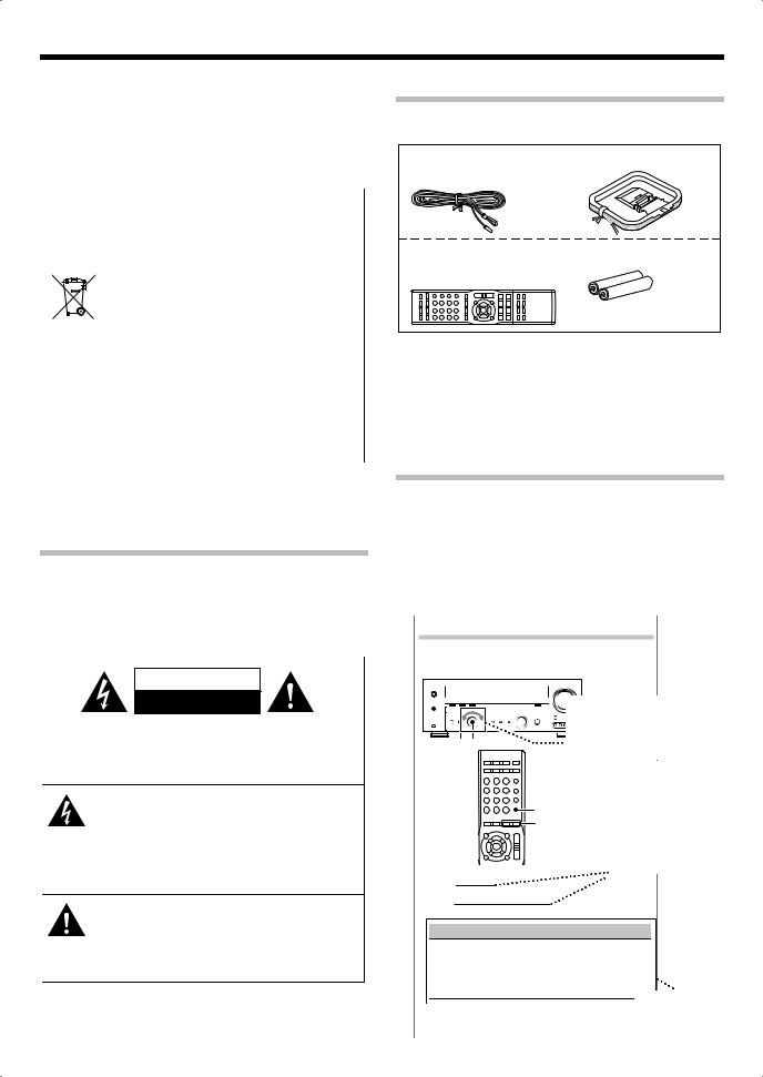
Unpacking
Unpack the unit carefully and make sure that all the accessories are present.
FM indoor antenna (1) |
AM loop antenna (1) |
Remote control unit (1) |
Batteries* (R03) (2) |
RC-R0517 |
|
* Batteries are attached to the packing material.
If any accessories are missing, or if the unit is damaged or fails to operate, notify your dealer immediately. If the unit was shipped to you directly, notify your shipper immediately. Kenwood recommends that you retain the original carton and packing materials in case you need to move or ship the unit in the future.
Keep this manual handy for future reference.
Notes on instructions
The operating instructions given in this manual assume that the user mainly operates the receiver using the remote control unit. When the same operation is also available on the main unit, the operating method is indicated in illustrations.
The [VOLUME CONTROL], [MULTI CONTROL] and [INPUT SELECTOR] knobs on the main unit are operated by turning the knobs clockwise or counterclockwise.
Example:
Getting into the setup mode
The setup procedure is identical for all of the setting elements. Once you remember the following procedure, you can easily set up other setting elements.
The knob on the main unit is pointed with an arrow to
 indicate that it can be turned in
SETUP MULTI CONTROL |
either direction. |
|
|
|
The operating |
|
|
procedures refer to |
|
|
those of the remote |
|
SETUP |
control unit. Some |
|
MULTI CONTROL operations are also |
|
|
/O |
available using the key |
|
|
(or knob) of the same |
|
|
name on the main unit. |
œ Press [SETUP] to enter the setup mode. 
∑Use [MULTI CONTROL 5/∞] to select the element to setup.
Display |
Selection |
|
|
"SP SETUP" |
Speaker setup |
|
|
"TEST TONE" |
Test tone |
|
|
"DISTANCE" |
Distance |
|
|
"LFE LVL" |
Low frequency effects level |
|
|
"EXIT" |
Exit the setup mode. |
Options to be |
|
|
|
||
é Press [SETUP] to get into the setup mode of the selected are listed selected element. in a table.
2 KRF-V5300D

IMPORTANT SAFETY INSTRUCTIONS
 Caution : Read this page carefully to ensure safe operation.
Read Instructions – All the safety and operating instructions should be read before the product is operated.
Retain Instructions – The safety and operating instructions should be retained for future reference.
Heed Warnings – All warnings on the product and in the operating instructions should be adhered to.
Follow Instructions – All operating and use instructions should be followed.
1.Cleaning – Unplug this product from the wall outlet before cleaning. Do not use liquid cleaners or aerosol cleaners. Use a damp cloth for cleaning.
2.Attachments – Do not use attachments not recommended by the product manufacturer as they may cause hazards.
3.Water and Moisture – This product shall not be exposed to dripping and splashing – for example, near a bath tub, wash bowl, kitchen sink, or laundry tub; in a wet basement; or near a swimming pool; and the like. Do not place an object containing liquid, such as a flower vase, on the appliance.
4.Accessories – Do not place this product on an
unstable cart, stand, tripod, bracket, or table. The  product may fall, causing serious injury to a child
 or adult, and serious damage to the product.
  Use only with a cart, stand, tripod, bracket, or
  table recommended by the manufacturer. Any mounting of the product should follow the manufacturer’s instructions, and should use a mounting accessory recommended by the manufacturer. A product and cart combination should be moved with care. Quick stops, excessive force, and uneven surfaces may cause the product and cart combination to overturn.
5.Ventilation – Slots and openings in the cabinet are provided for ventilation and to ensure reliable operation of the product and to protect it from overheating, and these openings must not be blocked or covered. The openings should never be blocked by placing the product on a bed, sofa, rug, or other similar surface. This product should not be placed in a built-in installation such as a bookcase or rack unless proper ventilation is provided or the manufacturer’s instructions have been adhered to.
6.Power Sources – This product should be operated only from the type of power source indicated on the product. If you are not sure of the type of power supply to your home, consult your product dealer or local power company.
7.CAUTION– Polarization – This product may be equipped with a polarized alternating-current line plug (a plug having one blade wider than the other). This plug will fit into the power outlet only one way. This is a safety feature. If you are unable to insert the plug fully into the outlet, try reversing the plug. If the plug should still fail to fit, contact your electrician to replace your obsolete outlet. Do not defeat the safety purpose of the polarized plug.
8.Power Cord Protection – Power-supply cords should be routed so that they are not likely to be walked on or pinched by items placed upon or against them, paying particular attention to cords at plugs, convenience receptacles, and the point where they exit from the product.
9.Lightning – For added protection for this product during a lightning storm, or when it is left unattended and unused for long periods of time, unplug it from the wall outlet and disconnect the antenna or cable system. This will prevent damage to the product due to lightning and power-line surges.
10.Overloading – Do not overload wall outlets, extension cords, or integral convenience receptacles as this can result in a risk of fire or electric shock.
11.Object and Liquid Entry – Never push objects of any kind into this product through openings as they may touch dangerous voltage points or short-out parts that could result in a fire or electric shock. Never spill liquid of any kind on the product.
12.Servicing – Do not attempt to service this product yourself as opening or removing covers may expose you to dangerous voltage or other hazards. Refer all servicing to qualified service personnel.
13.Damage Requiring Service – Unplug this product from the wall outlet and refer servicing to qualified service personnel under the following conditions:
a)When the power-supply cord or plug is damaged,
b)If liquid has been spilled, or objects have fallen into the product,
c)If the product has been exposed to rain or water,
d)If the product does not operate normally by following the operating instructions.
e)If the product has been dropped or damaged in any way, and
f)When the product exhibits a distinct change in performance
– this indicates a need for service.
g)If an abnormal smell or smoke is detected.
14.Replacement Parts – When replacement parts are required, be sure the service technician has used replacement parts specified by the manufacturer or have the same characteristics as the original part. Unauthorized substitutions may result in fire, electric shock, or other hazards.
15.Safety Check – Upon completion of any service or repairs to this product, ask the service technician to perform safety checks to determine that the product is in proper operating condition.
16.Wall or Ceiling Mounting – This product should be mounted to a wall or ceiling only as recommended by the manufacturer.
17.Heat – This product should be situated away from heat sources such as radiators, heat registers, stoves, or other products that produce heat. Do not place a flaming object, such as a candle or lantern, or near the product.
18.Power Lines – An outside antenna system should not be located in the vicinity of overhead power lines or other electric light or power circuits, or where it can fall into such power lines or circuits. When installing an outside antenna system, extreme care should be taken to keep from touching such power lines or circuits as contact with them might be fatal.
19.Outdoor Antenna Grounding – If an outside antenna or cable system is connected to the product, be sure the antenna or cable system is grounded so as to provide some protection against voltage surges and built-up static charges. Article 810 of the National Electrical Code, ANSI/NFPA 70, provides information with regard to proper grounding of the mast and supporting structure, grounding of the lead-in wire to an antenna discharge unit, size of grounding conductors, location of antenna-discharge unit, connection to grounding electrodes, and requirements for the grounding electrode.
EXAMPLE OF ANTENNA GROUNDING AS PER NATIONAL ELECTRICAL CODE
|
ANTENNA |
|
LEAD IN WIRE |
GROUND CLAMPS |
|
|
ANTENNA |
|
DISCHARGE UNIT |
|
(NEC SECTION 810-20) |
ELECTRIC SERVICE |
GROUNDING CONDUCTORS |
EQUIPMENT |
|
|
(NEC SECTION 810-21) |
|
GROUND CLAMP |
|
POWER SERVICE GROUNDING |
|
ELECTRODE SYSTEM |
NEC – NATIONAL ELECTRICAL CODE |
(NEC ART 250, PART H) |
|
Notes:
1.Item 7 is not required except for grounded or polarized equipment.
2.Item 19 complies with UL in the U.S.A.
English 3

Before applying power
Contents
Further adjustments .......................................... |
32 |
Fine adjustment of the sound ......................................... |
32 |
 To ensure safety, read the items carrying this marking carefully.
Before applying power ................................... |
2 |
Safety precautions........................................................... |
2 |
Unpacking.................................................................................. |
2 |
Notes on instructions............................................................. |
2 |
IMPORTANT SAFETY INSTRUCTIONS ............. |
3 |
Special features........................................................................ |
4 |
Names and functions of parts ............................. |
5 |
Main unit .................................................................................... |
5 |
Remote control unit ............................................................... |
6 |
Preparing the remote control............................................. |
7 |
Setting up the system .......................................... |
8 |
Speaker placement................................................................. |
8 |
Digital connections ................................................................ |
9 |
Connecting a DVD player (6-channel input) .............. |
10 |
Connecting audio components...................................... |
11 |
Connecting video components ...................................... |
12 |
Connecting video components |
|
(COMPONENT VIDEO) (For Australia) ................... |
13 |
Connecting the speakers................................................... |
14 |
Connecting the antennas.................................................. |
15 |
Connecting to the AV AUX jacks..................................... |
15 |
Speaker settings ................................................. |
16 |
Speaker setup (Easy Setup) .............................................. |
16 |
Speaker setting flow ........................................................... |
17 |
Getting into the setup mode ........................................... |
17 |
Speaker setup ("SP SETUP").............................................. |
18 |
Adjusting the speaker level ("TEST TONE") ................. |
18 |
Distance setting ("DISTANCE")......................................... |
19 |
Low frequency effects level ("LFE LVL") ........................ |
19 |
Normal Playback................................................. |
20 |
Preparing for playback ....................................................... |
20 |
Listening to a source component .................................. |
21 |
Listening to music with PURE AUDIO MODE.............. |
21 |
Adjusting the sound............................................................ |
22 |
Ambience effects ................................................ |
23 |
Surround modes................................................................... |
23 |
Surround play........................................................................ |
25 |
DVD 6-channel playback ................................................... |
26 |
Listening to radio broadcasts............................ |
27 |
Tuning (non-RDS) radio stations .................................... |
27 |
Using RDS (Radio Data System) ..................................... |
27 |
RDS Auto Memory ............................................................... |
28 |
Presetting radio stations manually ................................ |
28 |
Receiving preset stations .................................................. |
29 |
Receiving preset stations in order (P.CALL)................. |
29 |
Tuning by Program TYpe (PTY search) ......................... |
30 |
Using the RDS DISP. (display) key ................................... |
30 |
Recording ............................................................ |
31 |
Recording mode setting in digital audio source |
|
recording (main unit only)....................................... |
31 |
Recording audio (analog sources) ................................. |
31 |
Recording video.................................................................... |
31 |
Additional functions .......................................... |
34 |
Convenient functions ......................................................... |
34 |
Remote control operations for Kenwood DVD |
|
players ................................................................. |
35 |
Troubleshooting ................................................. |
36 |
Specifications...................................................... |
38 |
Special features
PURE AUDIO MODE¡
This is the mode for enjoying audio sources in high-quality stereo. It shuts off the power to the video circuitry as well as the display to eliminate their influence on the audio circuitry and improve the reproduced audio quality.
True home theater sound£
This unit incorporates a wide variety of surround modes to bring you maximum enjoyment from your video software. Select a surround mode according to your equipment or the software you are going to play and enjoy!
•Dolby Digital
•Dolby Pro Logic II
•DTS
•DSP surround modes
•DVD 6-channel input
4 KRF-V5300D
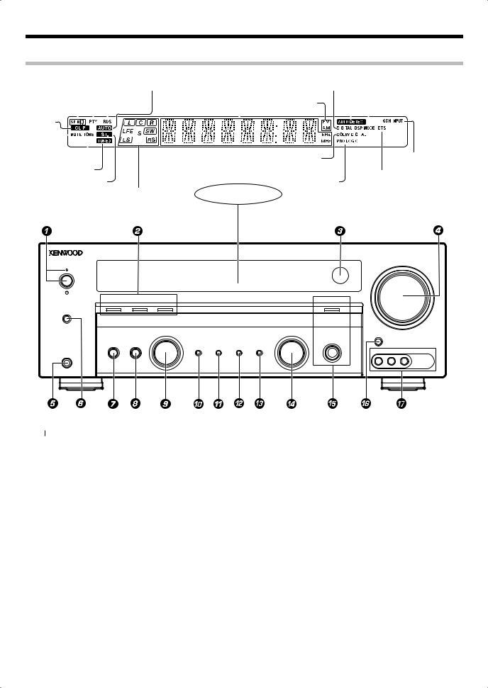
Names and functions of parts
Main unit
|
|
|
|
|
|
|
|
|
|
|
Frequency display, |
|
|
AUTO DETECT indicator |
||||||||
|
|
|
|
|
|
|
|
|
|
|
Input display, |
|
|
|||||||||
|
|
PTY indicator |
AUTO indicator |
Preset channel display, |
DIGITAL indicator |
|
|
|
|
|
|
|
|
|||||||||
|
|
Surround mode display |
|
|
|
|
DSP MODE |
|||||||||||||||
Speaker indicator |
|
RDS indicator |
|
|
|
|
|
|
||||||||||||||
|
|
|
Band indicators |
|
|
|
|
indicator |
||||||||||||||
CLIP indicator |
|
|
|
|
|
|
|
|
|
|
|
|
|
|
|
|
|
|
||||
|
|
|
|
|
|
|
|
|
|
|
|
|
|
|
|
|
|
|||||
|
|
|
|
|
|
|
|
|
|
|
|
|
|
|
|
|
|
|||||
MUTE |
|
|
|
|
|
|
|
|
|
|
|
|
|
|
|
|
|
|
|
|
|
|
|
|
|
|
|
|
|
|
|
|
|
|
|
|
|
|
|
|
|
||||
indicator |
|
|
|
|
|
|
|
|
|
|
|
|
|
|
|
|
|
|||||
|
|
|
|
|
|
|
|
|
|
|
|
|
|
|
||||||||
|
|
|
|
|
|
|
|
|
|
|
|
|
|
|
|
|
|
|
|
|||
|
|
|
|
|
|
|
|
|
|
|
|
|
|
|
|
|
|
|
||||
TONE indicator |
|
|
|
|
|
DOLBY DIGITAL |
|
|
|
|
|
|
|
6CH INPUT indicator |
||||||||
TUNED indicator |
|
|
|
|
|
indicator |
|
|
|
|
DTS indicator |
|||||||||||
|
|
|
|
|
|
|
|
|
|
|
||||||||||||
|
ST. indicator |
|
|
|
PRO LOGIC |
|
|
|
|
|||||||||||||
|
|
|
|
|
|
|
|
|
|
|
|
|||||||||||
|
|
|
|
|
|
|
|
|
|
|
|
|
indicator |
|
|
|
|
|
|
|
|
|
Input channel status indicator |
Display |
|
VOLUME CONTROL
DOLBY DIGITAL |
DTS |
ACTIVE EQ |
|
PURE AUDIO MODE |
SPEAKERS ON/OFF |
|
|
|
|
|
|
MULTI CONTROL |
INPUT SELECTOR |
AV AUX |
|
|
|
|
|
|
|
|
|
PURE AUDIO MODE |
LISTEN MODE |
SETUP |
|
BAND AUTO/MONO ACTIVE EQ INPUT MODE |
|
VIDEO L-AUDIO-R
PHONES
1  (power) key
Standby indicator
Switch the unit ON and standby. When the unit is in standby mode, the standby indicator is lit.
2Surround LED indicators DOLBY DIGITAL indicator
Light when this unit is in the Dolby Digital mode.
DTS indicator
Light when in the DTS mode.
ACTIVE EQ indicator
Light when in the ACTIVE EQ mode.
3 Remote sensor
4 VOLUME CONTROL knob
5PHONES jack
Use for headphone listening.
6SPEAKERS ON/OFF key
Use to turn the speakers ON/OFF.
7 LISTEN MODE key |
∞ |
Use to select the listen mode.
8 SETUP key |
& ^ AV AUX key |
Use to select the speakers' settings etc.
9MULTI CONTROL knob
Use to control a variety of settings.
0BAND key
Use to select the broadcast band.
!AUTO/MONO key
Use to select the auto tuning or
manual tuning mode. |
¶ |
Use to select a recording mode. ⁄ |
|
@ ACTIVE EQ key |
™ |
Use to select ACTIVE EQ setting. |
|
# INPUT MODE key |
) |
Use to select AV AUX source.
&AV AUX jack
Use to connect a device such as a camcorder and a game player.
Standby mode
While the standby indicator is lit, a small amount of power is supplied to the system to back up the memory. This is called standby mode. Under the condition, the system can be turned ON by the remote control unit.
Use to switch between full auto, digital and analog inputs.
$INPUT SELECTOR knob
Use to select the input sources.
% PURE AUDIO MODE key ¡
PURE AUDIO MODE indicator
Use to select PURE AUDIO MODE. When this mode is on, the PURE AUDIO MODE indicator is lit.
English 5
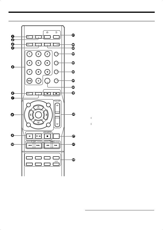
Names and functions of parts
Remote control unit
AUTO MEMORY MEMORY |
|
|
|
ANGLE |
REPEAT |
DVD |
RECEIVER |
RDS DISP. |
PTY |
|
|
AUDIO |
SUBTITLE |
DIMMER |
ACTIVE EQ |
BASS BOOST
TONE
SOUND
4 PTY key |
º |
Use for PTY search.
SUBTITLE key
Use to operate the Kenwood DVD player.*
5Numeric keys
Use to call up preset stations.
Use to operate the Kenwood DVD player.*
6 LISTEN MODE key |
∞ |
Use to select a listen mode. |
|
7 PURE AUDIO MODE key |
¡ |
Select PURE AUDIO MODE.
85, ∞, 2, 3 keys
ENTER key TOP MENU key MENU key RETURN key ON SCREEN key
|
EASY SETUP |
SETUP |
|
|
|
PURE AUDIO |
|
|
LISTEN MODE MODE |
MULTI CONTROL |
|
TOP MENU |
MENU |
|
ENTER
RETURN |
ON SCREEN |
BAND
MUTE
TUNER |
CD/DVD |
MD/TAPE |
AV AUX |
VIDEO 1 |
VIDEO 2 |
DVD/6CH |
|
1 AUTO MEMORY key •
Use for auto memory of RDS and FM radio stations.
ANGLE key
Use to operate the Kenwood DVD player.*
2 MEMORY key |
• |
Use for manual memory of radio stations.
REPEAT key
Use to operate the Kenwood DVD player.*
3 RDS DISP. key |
º |
Use to display RDS information.
AUDIO key
Use to operate the Kenwood DVD player.*
Use to operate the Kenwood DVD player.*
98 key
Use to operate the Kenwood DVD player.*
BAND key
Use to select the broadcast band.
6 key
Use to operate the Kenwood DVD player.*
AUTO/MONO key |
¶ |
Use to select the auto tuning or manual tuning mode.
7 key
Use to operate the Kenwood DVD player.*
0 P.CALL 4/¢ keys
Use to call preset channel. ª Use to operate the Kenwood DVD player.*
!  RECEIVER key
Use to turn this unit on and off.
 DVD key
Use to turn on the Kenwood DVD player on and off.
@ ACTIVE EQ key |
™ |
Use to select ACTIVE EQ setting. |
|
# DIMMER key |
› |
Use to adjust the brightness of the display and the indicators. |
|
$ BASS BOOST key |
™ |
Use to select the maximum adjustment setting for the low frequency range.
% TONE key |
™ |
Use to switch the status of TONE control. |
|
^ SOUND key |
¤ |
Use to adjust the sound quality and ambience effects. |
|
& SETUP key |
& |
Use to select the speakers' settings. |
|
* EASY SETUP key |
^ |
Use to select speaker setting.
(MULTI CONTROL 5/∞ keys
Select an setup item.
)VOLUME %/fi keys
Use to adjust volume setting.
¡MUTE key
Use to temporarily mute the sound.
™TUNING 1/¡ keys
Use to select the radio station.
Use to operate the Kenwood DVD player.*
£Input source keys
Use to select the input source.
Note:
•* For how to be able to use the keys to operate the Kenwood
DVD player, see <Remote control operations for Kenwood DVD players> fi.
6 KRF-V5300D
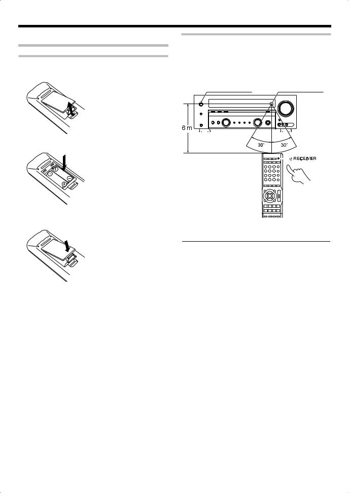
Preparing the remote control
Loading batteries
œ Remove the cover.
∑ Insert batteries.
Operation
When the Standby indicator is lit, the power turns ON when you press [ RECEIVER] on the remote control unit. When the power comes ON, press the key you want to operate.
Operating range (Approx.)
Standby indicator |
Remote sensor |
||||||
|
|
|
|
|
|
|
|
|
|
|
|
|
|
|
|
|
|
|
|
|
|
|
|
|
|
|
|
|
|
|
|
• Insert two (R03) batteries following the polarity indications.
é Close the cover.
Infrared ray system
•When pressing more than one remote control key successively, press the keys securely by leaving an interval of 1 second or more between keys.
Notes:
1.The supplied batteries may have shorter lives than ordinary batteries due to use during operation checks.
2.When the remote-controllable distance gets shorter than before, replace both batteries with new ones.
3.Placing the remote sensor in direct sunlight, or in direct light from a high frequency fluorescent lamp may cause a malfunction.
In such a case, change the location of the system installation to prevent malfunction.
English 7
Setting up the system
Make connections as shown in the following pages.
When connecting the related system components, be sure to refer to the instruction manuals supplied with the components you are connecting.
Do not connect the power cord to a wall outlet until all connections are completed.
Notes:
1.Be sure to insert all connection cords securely. If their connections are imperfect, the sound may not be produced or there will be noise interference.
2.Be sure to remove the power cord from the AC outlet before plugging or unplugging any connection cords. Plugging/ unplugging connection cords without disconnecting the power cord can cause malfunctions and may damage the unit.
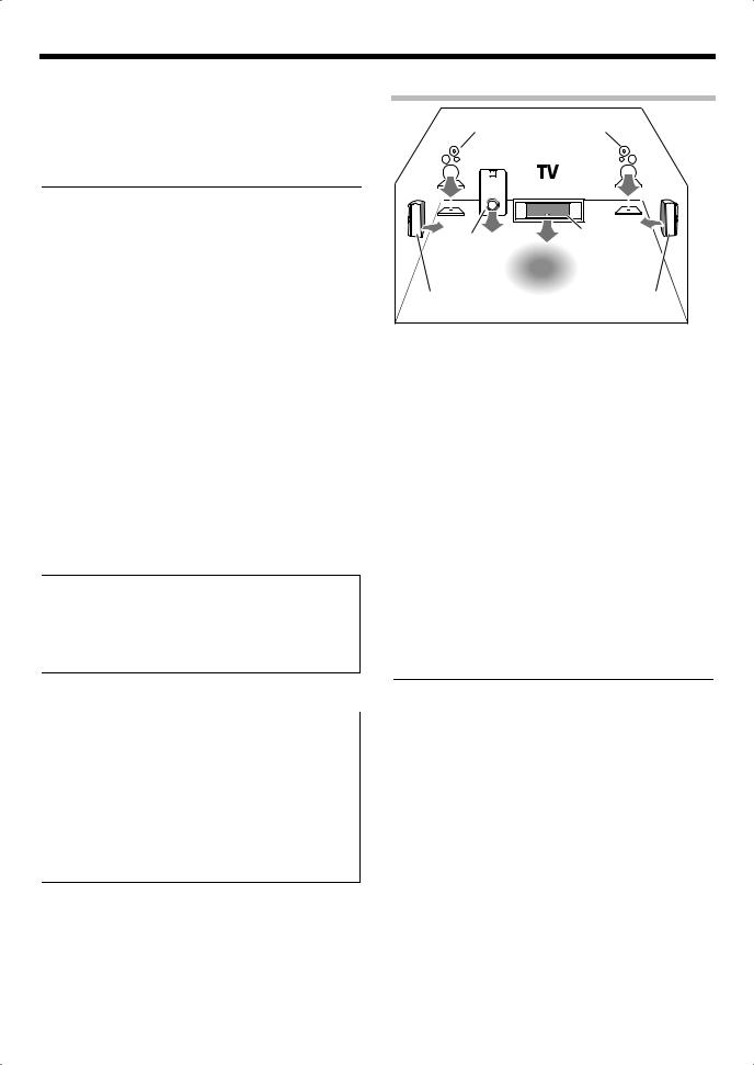
Speaker placement
Front speaker |
|
Front speaker |
||||||||
|
|
|
|
|
|
|
|
|
|
|
|
|
|
|
|
|
|
|
|
|
|
|
|
|
|
|
|
|
|
|
|
|
Subwoofer |
Center speaker |
|
|
|
Listening |
|
position |
Surround speaker |
Surround speaker |
Analog connections
Audio connections are made using RCA pin cords. These cables transfer stereo audio signal in an "analog" form. This means the audio signal corresponds to the actual audio of two channels.
These cables usually have 2 plugs at each end, red for the right channel and white for the left channel. These cables are usually packed together with the source unit, or are available at your local electronics retailer.
Microcomputer malfunction
If operation is not possible or an erroneous display appears, even though all connections have been made properly, reset the microcomputer by referring to <Troubleshooting>. fl
¤CAUTION
The power of this equipment will not be completely cut off from the wall outlet when the power switch is turned off. Install the equipment so that the wall outlet is easily accessible and, in case of emergency, immediately unplug the power cord from the wall outlet.
¤CAUTION
Be sure to adhere to the following, or proper ventilation will be blocked causing damage or fire hazard.
•Leave some space around the unit (from the largest outside dimension including projection) equal to or greater than, shown below.
Side panel : 10 cm Back panel : 10 cm
•This unit is using the cooling fan. Do not place the unit onto a bed, a sofa, a carpet, or similar. Sucked-in dust can cause fire.
Front speakers:
Place the left and right speakers at each side of your TV. Angle the speakers towards the listening area to enhance the stereo effect.
Center speaker:
Place the center speaker on the center between the front left and right speakers. Tilt the speaker upward or down-ward so that it is directly facing the listening area.
Surround speakers:
Place the surround speakers as high as possible, either directly to the sides of the listening area or else slightly behind the listening area. Adjust the angles so that these speakers are facing directly towards the listeners.
Subwoofer:
Usually, place the subwoofer in the front center position in the listening room, near one of the front speakers. (Since the subwoofer has less directivity than other speakers, it can be placed almost in any position that can offer the best low frequency reproduction according to the room layout.)
Note:
•Although the ideal surround system consists of all the speakers listed above, if you don’t have a center speaker or a subwoofer, you can divide those signals between the available speakers in the speaker settings steps to obtain the best possible surround reproduction from the speakers you have available.
8 KRF-V5300D

Digital connections
The DIGITAL IN jacks can accept DTS, Dolby Digital, or PCM signals. Connect components capable of outputting DTS, Dolby Digital, or standard PCM (CD) format digital signals.
If you have connected any digital components to this unit, be sure to read the <Selecting the input mode> ) carefully.
To AC wall outlet |
|
|
|
|
|
|
|
|
|
|
|
|
|
|
|
|
|
|
|
|
|
|
|
|
|
|
COAXIAL |
OPTICAL |
OPTICAL |
||||||||||
DVD |
|
/ |
|
6CH |
|
|
CD/DVD |
|
|
VIDEO2 |
|
|
|
|
|
|
|
|
|
|
|
|
|
|
|
DIGITAL IN
Optical fiber |
Optical fiber |
cable |
cable |
OPTICAL DIGITAL OUT  (AUDIO)
CD or DVD player
Component with DTS, Dolby Digital, or PCM
OPTICAL DIGITAL OUT* OPTICAL DIGITAL OUT (AUDIO)
Note:
• * Connect the video signal and analog audio signals to the VIDEO 2 jacks. (<Connecting video components> @)
English 9
Setting up the system
Connecting a DVD player (6-channel input)
If you have connected a DVD player to this unit with digital connection, be sure to read the <Selecting the input mode> ) carefully.
To AC wall outlet
|
|
|
VIDEO2 |
|
|
|
CENTER |
IN |
|
|
|
|
OUT |
|
|
|
|
VIDEO1 |
|
|
|
SUB |
IN |
|
|
|
|
|
|
|
|
WOOFER |
OPTICAL |
|
|
|
COAXIAL |
|
|
FRONT |
SURROUND |
DVD/6CH |
CD/DVD |
|
DIGITAL IN |
|
|||
|
DVD / 6CH IN |
MONITOR |
||
|
|
|
DVD |
|
|
|
|
IN |
OUT |
|
|
|
VIDEO |
|
FRONT |
SURROUND |
SUBWOOFER |
CENTER |
OUT L/R |
OUT L/R |
OUT |
OUT |
|
|
|
COAXIAL DIGITAL |
DVD player |
|
OUT (AUDIO) |
|
|
|
VIDEO OUT |
|
|
|
(Yellow RCA |
|
|
|
pin cord) |
|
Note:
•For Australia only
If the DVD player has COMPONENT VIDEO OUT, COMPONENT VIDEO connection is possible. (<Connecting video components (COMPONENT VIDEO)> #)
10 KRF-V5300D
Connecting audio components
To AC wall outlet |
L
R
|
REC OUT PLAY IN REC OUT PLAY IN |
|
AUX CD/DVD |
MD / TAPE |
VIDEO 1 |
AUDIO
IN OUT
Casette deck or MD player
OUT
CD or DVD player
Other component
OUT
English 11

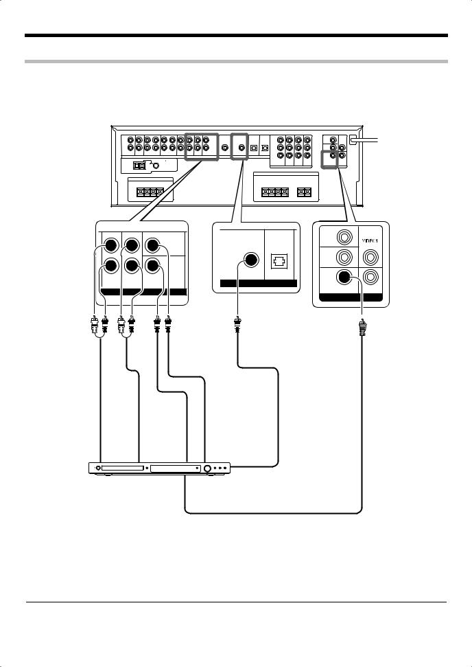
Setting up the system
Connecting video components
To AC wall outlet |
L
R
|
|
|
|
REC OUT PLAY IN REC OUT PLAY IN |
PLAY IN |
|
|||||
|
|
|
|
|
|
|
|
|
|
|
|
AUX |
|
|
CD/DVD |
|
MD |
|
/ |
TAPE |
VIDEO 1 |
VIDEO 2 |
|
AUDIO
VIDEO2 |
|
IN |
VIDEO1 |
|
OUT |
VIDEO1 |
|
IN |
|
DVD |
MONITOR |
IN |
OUT |
VIDEO |
|
|
|
|
|
|
|
|
AUDIO |
|
|
|
VIDEO |
||
|
|
|
|
|
|
|
OUT |
|
|
|
OUT |
||
|
|
|
|
|
|
|
|
|
|
|
|
|
|
|
|
|
|
|
|
|
|
|
|
|
|
|
|
|
|
|
|
|
|
|
|
|
|
|
|
|
|
|
|
|
|
|
|
|
|
|
|
|
|
|
|
|
|
|
|
|
|
|
|
|
|
|
|
|
|
|
|
|
|
|
|
|
|
|
|
|
|
|
|
DVD player
AUDIO |
|
|
|
OUT |
|
Video component with |
VIDEO OUT |
|
|
|
|
AUDIO IN |
|
recording function |
VIDEO IN |
|
|
||
|
|
||
VIDEO
IN
Monitor TV
Note:
• A video component with digital audio outputs should be connected to the VIDEO 2 jacks.
12 KRF-V5300D
 Loading...