


Kenmore 79681362910, 79681462910, 79681463910, 79681562910, 79681563910 Owner’s Manual
...Use & Care Guide
Manual de Uso y Cuidado
Models/Modelos: 796.8156*, 796.9156* 796.8146*, 796.9146* 796.8136*, 796.9136*
Kenmore® Dryer
Secadora
* = color number, número de color
MFL70442637
Transform SR Brands Management LLC
Ho man Estates, IL 60179
www.kenmore.com
®

TABLE OF CONTENTS |
|
|
IMPORTANT SAFETY INSTRUCTIONS .................... |
|
3-7 |
Grounding Requirements ............................................ |
|
4 |
FCC Notice .................................................................... |
|
5 |
Wireless Module Specifications ................................. |
|
5 |
Open Source Software Notice.................................... |
|
5 |
FEATURES AND BENEFITS |
|
|
Key Parts and Components ........................................ |
|
8 |
INSTALLATION INSTRUCTIONS |
|
|
Key Dimensions and Specifications .......................... |
|
9 |
Location Requirements ................................................ |
|
9 |
Choose the Proper Location ....................................... |
|
9 |
Clearances .................................................................... |
|
9 |
Installation with Optional Pedestal Base |
|
|
or Stacking Kit ........................................................... |
|
10 |
Accessories ................................................................. |
|
10 |
Connecting Gas Dryers ........................................ |
|
11-12 |
Gas Requirements (Gas Models Only) ............. |
11 |
|
Electrical Requirements ....................................... |
|
11 |
Connecting Electric Dryers ................................. |
|
13-14 |
Electrical Requirements....................................... |
|
13 |
Venting the Dryer ................................................. |
|
15-16 |
Connecting the Inlet Hose......................................... |
|
17 |
Leveling the Dryer ..................................................... |
|
18 |
Reversing the Door Swing ........................................ |
|
18 |
Final Installation Check ............................................ |
|
19 |
Installation Test (Duct Check) .................................. |
|
20 |
Restricted or Blocked Airflow................................... |
|
21 |
HOW TO USE |
|
|
Control Panel Features |
|
|
Model 8156*/9156* ............................................ |
|
22 |
Model 8146*/9146*........................................... |
|
26 |
Model 8136*/9136* ........................................... |
|
30 |
Operating the Dryer |
|
|
Model 8156*/9156* ............................................ |
|
23 |
Model 8146*/9146*........................................... |
|
27 |
Model 8136*/9136* ........................................... |
|
31 |
Cycle Guide |
|
|
Model 8156*/9156* ..................................... |
|
24-25 |
Model 8146*/9146*..................................... |
|
28-29 |
Model 8136*/9136* ...................................... |
|
32-33 |
Sorting Loads ............................................................ |
|
34 |
Loading the Dryer .................................................... |
|
34 |
Time and Status Display .......................................... |
|
35 |
Cycle Modifier Buttons ............................................. |
|
36 |
Cycle Options and Special Features ..................... |
|
37 |
Wrinkle Guard ................................................... |
|
37 |
Control Lock ....................................................... |
|
37 |
My Cycle ............................................................. |
|
37 |
Damp Dry Signal ................................................ |
|
37 |
Drum Light ........................................................... |
|
37 |
Energy Saver ....................................................... |
|
37 |
Steam Features ................................................... |
|
37-38 |
Important Notes About Steam Functions ....... |
37 |
|
Using the Steam Refresh Cycle ......................... |
|
38 |
Using the Steam Sanitize Cycle......................... |
|
38 |
Using the Static Shield Option .......................... |
|
38 |
Accela Steam ....................................................... |
|
38 |
Steam Cycle Guide ............................................. |
|
38 |
Smart Features .................................................... |
|
39-40 |
USER MAINTENANCE INSTRUCTIONS |
|
|
Regular Cleaning ...................................................... |
|
41 |
Cleaning the Exterior .......................................... |
|
41 |
Cleaning the Interior ........................................... |
|
41 |
Cleaning Around and Under the Dryer ............ |
41 |
|
Cleaning the Lint Filter ....................................... |
|
41 |
Maintaining the Exhaust System............................. |
|
42 |
TROUBLESHOOTING GUIDE |
|
|
FAQs ........................................................................... |
|
43 |
Before Calling for Service ................................ |
|
43-46 |
WARRANTY ................................................................... |
|
47 |
SERVICE.......................................................... |
Back Cover |
|
PRODUCT RECORD
In the space below, record the date of purchase, model, and serial number of your product. You will find the model and serial number printed on an identification plate located inside the dryer door. Have these items of information available whenever you contact Sears concerning your product.
Model No.
Date of Purchase
Serial No.
Save these instructions and your sales receipt for future reference.
2
IMPORTANT SAFETY INSTRUCTIONS
READ ALL INSTRUCTIONS BEFORE USE
Your safety and the safety of others is very important.
We have provided many important safety messages in this manual and on your appliance. Always read and obey all safety messages.
This is the safety alert symbol.
This symbol alerts you to potential hazards that can kill or hurt you and others.
All safety messages will follow the safety alert symbol and either the word DANGER or WARNING. These words mean:
 DANGER: Indicates a hazardous situation which, if not avoided, will result in death or serious injury.
 WARNING: Indicates a hazardous situation which, if not avoided, could result in death or serious injury.
CAUTION: Indicates a hazardous situation which, if not avoided, could result in minor or moderate injury.
All safety messages will tell you what the potential hazard is, tell you how to reduce the chance of injury, and tell you what can happen if the instructions are not followed.
 WARNING: For your safety, the information in this manual must be followed to minimize the risk of fire or explosion, electric shock, or to prevent property damage, personal injury,
or loss of life.
 WARNING:
FIRE HAZARD
Failure to follow safety warnings exactly could result in serious injury, death or property damage.
•Do not install a booster fan in the exhaust duct.
•Install all clothes dryers in accordance with the installation instructions of the manufacturer of the dryer.
 WARNING:
FIRE OR EXPLOSION HAZARD
Failure to follow safety warnings exactly could result in serious injury, death or property damage.
•Do not store or use gasoline or other flammable vapors and liquids in the vicinity of this appliance or any other appliances.
•Installation and service must be performed by a qualified installer, service agency, or the gas supplier.
WHAT TO DO IF YOU SMELL GAS:
1.Do not try to light a match or cigarette, or turn on any gas or electrical appliance.
2.Do not touch any electrical switches. Do not use any phones in your building.
3.Clear the room, building, or area of all occupants.
4.Immediately call your gas supplier from a neighbor’s phone. Carefully follow the gas supplier’s instructions.
5.If you cannot reach your gas supplier, call the fire department.
•Do not install a clothes dryer with flexible plastic venting materials. If a flexible metal (foil type) duct is installed, it must be of a specific type identified by the appliance manufacturer as suitable for use with clothes dryers. Flexible venting materials are known to collapse, be easily crushed, and trap lint. These conditions will obstruct clothes dryer airflow and increase the risk of fire.
SAVE THESE INSTRUCTIONS
3

IMPORTANT SAFETY INSTRUCTIONS
BASIC SAFETY PRECAUTIONS
 WARNING: To reduce the risk of fire, electric shock, or injury to persons when using this appliance, follow basic precautions, including the following:
•Read all instructions before using the dryer.
•Before use, the dryer must be properly installed, as described in this manual.
•Do not place items exposed to cooking oils in your dryer. Items contaminated with cooking oils may contribute to a chemical reaction that could cause a load to catch fire. To reduce the risk of fire due to contaminated loads, the final part of a tumble dryer cycle occurs without heat (cool down period). Avoid
stopping a tumble dryer before the end of the drying cycle unless all items are quickly removed and spread out so that the heat is dissipated.
•Do not dry articles that have been previously cleaned in, washed in, soaked in, or spotted with gasoline, dry-cleaning solvents, or other flammable or explosive substances, as they give o vapors that could ignite or explode.
•Do not reach into the dryer if the drum or any other part is moving.
•Do not place any part of your body, such as hands or feet, or metal objects under the dryer.
•Do not let your hand get pinched when opening or closing the dryer door.
•Do not repair or replace any part of the dryer or attempt any servicing unless specifically recommended in this Use and Care Guide or in published user-repair instructions that you understand and have the skills to carry out.
•Do not tamper with controls.
GROUNDING REQUIREMENTS
This appliance must be grounded. In the event of malfunction or breakdown, grounding will reduce the risk of electric shock by providing a path of least resistance for electric current. This appliance must be
equipped with a cord having an equipment-grounding conductor and a grounding plug. The plug must be plugged into an appropriate outlet that is properly installed and grounded in accordance with all local codes and ordinances.
•Before the dryer is removed from service or discarded, remove the door to the drying compartment.
•Do not allow children to play on or in the dryer. Close supervision of children is necessary when the dryer is used near children.
•Do not allow living animals such as pets to be inside the dryer drum.
•Do not use fabric softeners or products to eliminate static unless recommended by the manufacturer of the fabric softener or product.
•Do not use heat to dry articles containing foam rubber or similarly textured rubber-like materials.
•Keep area around the exhaust opening and adjacent surrounding areas free from the accumulation of lint, dust, and dirt.
•The interior of the dryer and exhaust vent should be cleaned periodically by qualified service personnel.
•Do not install or store the dryer where it will be exposed to the weather.
•Always check the inside of the dryer for foreign objects.
•Clean the lint filter before or after each load.
•Gas appliances can cause minor exposure to four potentially harmful substances, namely benzene, carbon monoxide, formaldehyde, and soot, caused primarily by the incomplete combustion of natural gas or LP fuels. Properly adjusted dryers will minimize incomplete combustion. Exposure to these substances
can be minimized further by properly venting the dryer to the outdoors.
 WARNING: Improper connection of the equipment-grounding conductor can result in a risk of electric shock. Check with a qualified electrician or service person if you are in doubt as to whether the appliance is properly grounded. Do not modify the plug provided with the appliance. If it will not fit the outlet, have a proper outlet installed by a qualified electrician. This appliance must be connected to a grounded metal, permanent wiring system or an equipment grounding conductor must be run with the circuit conductors and connected to the equipment grounding terminal or lead on the appliance. Electric shock can result if the dryer is not properly grounded.
4

FCC NOTICE
(for transmitter module contained in this product)
This equipment has been tested and found to comply with the limits for a Class B digital device, pursuant to Part 15 of the FCC Rules. These limits are designed to provide reasonable protection against harmful
interference in a residential installation. This equipment generates, uses, and can radiate radio frequency energy and, if not installed and used in accordance with the instructions, may cause harmful interference to radio communications. However, there is no guarantee that interference will not occur in a particular installation.
If this equipment does cause harmful interference to radio or television reception, which can be determined by turning the equipment o and on, the user is encouraged to try to correct the interference by one or more of the following measures:
-Reorient or relocate the receiving antenna.
-Increase the separation between the equipment and receiver.
-Connect the equipment to an outlet on a circuit
di erent from that to which the receiver is connected.
-Consult the dealer or an experienced radio/TV technician for help.
This device complies with part 15 of the FCC rules. Operation is subject to the following two conditions:
(1)this device may not cause harmful interference, and
(2)this device must accept any interference received, including interference that may cause undesired operation of the device.
Any changes or modifications in construction of this device which are not expressly approved by the party responsible for compliance could void the user's authority to operate the equipment.
FCC RF Radiation Exposure Statement
This equipment complies with FCC radiation exposure limits set forth for an uncontrolled environment. This transmitter must not be co-located or operating in conjunction with any other antenna or transmitter.
This equipment should be installed and operated with a minimum distance of 20 cm (7.8 inches) between the antenna and your body. Users must follow the
specific operating instructions for satisfying RF exposure compliance.
|
IMPORTANT SAFETY INSTRUCTIONS |
|
WIRELESS MODULE SPECIFICATIONS |
||
|
|
|
Model |
|
LCW-004 |
Frequency |
|
2412–2462 MHz |
Range |
|
|
Maximum |
|
IEEE 802.11b: 22.44 dBm |
Output |
|
IEEE 802.11g: 24.68 dBm |
Power |
|
IEEE 802.11n: 24.11 dBm |
|
|
|
|
|
|
OPEN SOURCE SOFTWARE NOTICE
To obtain the source code that is contained in this product under LGPL and other open source licenses, visit http://kenmore.com/opensource. In addition to the source code, all referred license terms, warranty disclaimers, and copyright notices are available for download.
5

IMPORTANT SAFETY INSTRUCTIONS
SAFETY INSTRUCTIONS FOR INSTALLATION
 WARNING: To reduce the risk of fire, electric shock, or injury to persons when using this appliance, follow basic precautions, including the following:
• Properly ground the dryer to conform with all governing |
• Remove all packing items and dispose of all shipping |
|
codes and ordinances. Follow details in the installation |
materials properly. Failure to do so can result in fire, |
|
instructions. Electric shock can result if the dryer is not |
explosion, burns, or death. |
|
properly grounded. |
• Place the dryer at least 18 inches above the floor for |
|
• Before use, the dryer must be properly installed as |
||
a garage installation. Failure to do so can result in fire, |
||
described in this manual. Electric shock can result if the |
explosion, burns, or death. |
|
dryer is not properly grounded. |
• Keep all packaging from children. Packaging material |
|
• Install and store the dryer where it will not be exposed |
||
can be dangerous for children. There is a risk of |
||
to temperatures below freezing or exposed to |
su ocation. |
|
the weather. |
• Do not install near items that produce heat or open |
|
• All repairs and servicing must be performed by an |
||
flame such as stoves or cooking ovens. Failure to follow |
||
authorized service technician unless specifically |
this warning can cause product deformation, smoke and |
|
recommended in this Use & Care Guide. Use only |
fire. |
|
authorized factory parts. Failure to follow this warning |
• Do not place candles or cigarettes on top of the |
|
can cause serious injury, fire, electric shock, or death. |
||
• To reduce the risk of electric shock, do not install the |
product. Failure to follow this warning can cause |
|
product deformation, smoke and fire. |
||
dryer in humid spaces. Failure to follow this warning |
• Remove all protective vinyl film from the product. |
|
can cause serious injury, fire, electric shock, or death. |
||
• Connect to a properly rated, protected, and sized |
Failure to do so can cause product deformation, smoke |
|
and fire. |
||
power circuit to avoid electrical overload. Improper |
|
|
power circuits can melt, creating risk of electric shock |
|
|
and/or fire hazard. |
|
Exhaust/Ducting:
•Gas dryers MUST be exhausted to the outside. Failure to follow these instructions can result in fire or death.
•The dryer exhaust system must be exhausted to the outside of the dwelling. If the dryer is not exhausted outdoors, some fine lint and large amounts of moisture will be expelled into the laundry area. An accumulation of lint in any area of the home can create a health and fire hazard.
•Use only rigid metal or flexible metal 4 inch diameter duct inside the dryer cabinet or for exhausting to the outside. Use of plastic or other combustible ductwork can cause a fire. Punctured ductwork can cause a fire if it collapses or becomes otherwise restricted in use or during installation.
•Ductwork is not provided with the dryer, and you should obtain the necessary ductwork locally. The end cap should have hinged dampers to prevent backdraft when the dryer is not in use. Failure to follow these instructions can result in fire or death.
•The exhaust duct must be 4 inches (10.2 cm) in diameter with no obstructions. The exhaust duct should be kept as short as possible. Make sure to clean any old ducts before installing your new dryer.
Failure to follow these instructions can result in fire or death.
•Rigid or semi-rigid metal ducting is recommended for use between the dryer and the wall. In special installations when it is impossible to make a connection with the above recommendations, a UL listed flexible metal transition duct may be used between the dryer and wall connection only. The use of this ducting will a ect drying time. Failure to follow these instructions can result in fire or death.
•DO NOT use sheet metal screws or other fasteners which extend into the duct that could catch lint and reduce the e ciency of the exhaust system. Secure all joints with duct tape. For complete details, follow the Installation Instructions. Failure to follow these instructions can result in fire or death.
6

IMPORTANT SAFETY INSTRUCTIONS
SAFETY INSTRUCTIONS FOR STEAM FUNCTIONS
 WARNING: To reduce the risk of fire, electric shock, or injury to persons when using this appliance, follow basic precautions, including the following:
•Do not open the dryer door during steam cycles.
Failure to follow these instructions can result in a burn hazard.
•Do not dry articles that have been previously cleaned in, washed in, soaked in, or spotted with gasoline, dry-cleaning solvents, or other flammable or explosive substances, as they give o vapors that could ignite or explode. Failure to follow these instructions can result in fire or death.
•Do not touch the steam nozzle in the drum during or after the steam cycle. Failure to follow these instructions can result in a burn hazard.
SAFETY INSTRUCTIONS FOR CONNECTING ELECTRICITY
 WARNING: To reduce the risk of fire, electric shock, or injury to persons when using this appliance, follow basic precautions, including the following:
•Do not, under any circumstances, cut or remove the ground prong from the power cord. To prevent personal injury or damage to the dryer, the electrical power cord must be plugged into a properly grounded outlet.
•For personal safety, this dryer must be properly grounded. Failure to do so can result in electric shock or injury.
•Refer to the installation instructions in this manual for specific electrical requirements for your model.
Failure to follow these instructions can create an electric shock hazard and/or a fire hazard.
•This dryer must be plugged into a properly grounded outlet. Electric shock can result if the dryer is not properly grounded. Have the wall outlet and circuit checked by a qualified electrician to make sure the outlet is properly grounded. Failure to follow these instructions can create an electric shock hazard and/or a fire hazard.
•The dryer should always be plugged into its own individual electrical outlet which has a voltage rating that matches the rating plate. This provides the best performance and also prevents overloading house wiring circuits which could cause a fire hazard from overheated wires.
•Never unplug your dryer by pulling on the power cord. Always grip the plug firmly and pull straight out from the outlet. The power cord can be damaged, resulting in a risk of fire and electric shock.
•Repair or replace immediately all power cords that have become frayed or otherwise damaged. Do not use a cord that shows cracks or abrasion damage along its length or at either end. The power cord can melt, creating an electric shock and/or fire hazard.
•When installing or moving the dryer, be careful not to pinch, crush, or damage the power cord. This will prevent injury and prevent damage to the dryer from fire and electric shock.
SAVE THESE INSTRUCTIONS
7

FEATURES AND BENEFITS
 KEY PARTS AND COMPONENTS
There are several important components that are referenced in this manual.
A |
EASY-TO-USE CONTROL PANEL |
A |
D |
|
Rotate the cycle selector knob to select the desired |
|
|
|
|
|
|
|
dry cycle. Add cycle options or adjust settings with |
|
B |
|
the touch of a button. |
|
|
B |
TIME AND STATUS DISPLAY |
|
C |
|
I |
||
|
The easy-to-read LED display shows cycle status |
|
|
|
and estimated time remaining. |
|
|
C |
CYCLE MODIFIERS |
|
|
|
Adjust the cycle settings such as temperature and |
|
|
|
dry level with the touch of a button. |
|
F |
|
NOTE: Not all settings are available for all cycles. |
|
|
|
|
|
|
D |
CHECK VENT |
|
|
|
(Duct Blockage Sensing System) |
|
|
|
The Check Vent (duct blockage sensing system) |
|
|
|
detects and alerts you to blockages in the exhaust |
|
|
|
system that reduce airflow from the dryer. |
|
G |
|
Maintaining clean exhaust system ducts improves |
|
|
|
|
|
|
|
operating e ciency and helps minimize service |
|
|
|
calls, saving you money. |
|
|
|
E |
H |
|
EULTRA-CAPACITY DRUM WITH DRUM LIGHT
The ultra-large drum o ers superior durability. Press and hold the Energy Saver button for 3
|
seconds to turn on the drum light during a cycle. |
Power Cord |
|
|
The light also comes on when the door is opened, |
Terminal Block |
|
|
Location |
||
|
if the control panel is activated. |
Access Panel |
|
|
(Gas Models) |
||
|
|
(Electric Models) |
|
F |
EASY-ACCESS REVERSIBLE DOOR |
|
|
|
|
||
|
The wide-opening, see-through glass door |
|
|
|
provides easy access for loading and unloading. |
|
|
|
Door swing can be reversed to adjust for |
|
|
|
installation location. |
|
|
G |
FRONT-MOUNT LINT FILTER |
|
|
|
The front-mount lint filter allows for easy access |
|
|
|
and cleaning between loads. |
|
|
H LEVELING FEET
Four leveling feet (two in front, and two in back) adjust to improve dryer stability on uneven floors.
I REMOTE START
Control your dryer remotely using the Kenmore
Smart mobile app.
Inlet Valve
Exhaust Duct
Gas Connection Outlet
Location
(Gas Models)
Rear of Dryer
8
|
|
|
INSTALLATION INSTRUCTIONS |
|
|
|
KEY DIMENSIONS AND SPECIFICATIONS |
||
|
|
|||
|
|
|
|
|
|
Description |
Dryer |
|
|
|
Electrical Requirements |
Refer to the rating label |
||
|
|
|
||
|
Gas Requirements* NG: |
4–10.5 inches WC (Water Column) |
|
|
|
|
|
||
|
Gas Requirements* LP: |
8–13 inches WC |
|
|
|
|
|
||
|
Dimensions |
27 in. (W) X 30 in. (D) X 39 in. (H), 51 3/4 in. (D with door open) |
|
|
|
|
|
68.6 cm (W) X 76.5 cm (D) X 99 cm (H), 130.5 cm (D with door open) |
|
|
|
|
||
|
Net Weight |
Electric: 8156*/8146* 123.1 lb. (55.8 kg), 8136* 118 lb. (53.5 kg) |
|
|
|
|
|
Gas: 9156*/9146* 124.4 lb. (56.4 kg), 9136* 121.3 lb. (55 kg) |
|
|
Drying Capacity |
IEC 7.4 cu. ft. |
||
|
|
|
|
|
|
*Gas Models Only |
|
|
|
 LOCATION REQUIREMENTS
IMPORTANT: Read all installation instructions completely before installing and operating your dryer. It is important that you review this entire manual before installing and using your dryer. It contains detailed instructions concerning electrical connections, gas connections and exhaust requirements.
 CHOOSE THE PROPER LOCATION
•Store and install the dryer where it will not be exposed to temperatures below freezing or exposed to outdoor weather conditions.
•Choose a location with a solid, level floor.
•If the dryer is being installed in a garage, place the dryer at least 18 inches (45.7cm) above the floor.
•Properly ground the dryer to conform with all governing codes and ordinances.
•To reduce the risk of electric shock, do not install the dryer in damp or wet locations.
NOTE: Installing the dryer in a humid space, or installing or storing the dryer where it will be exposed to the weather or freezing temperatures, may result in rust or other damage that is not covered by the product warranty.
IMPORTANT: If you are installing your dryer in a manufactured or mobile home, please refer to the
Special Electrical Requirements for Mobile or Manufactured Homes section.
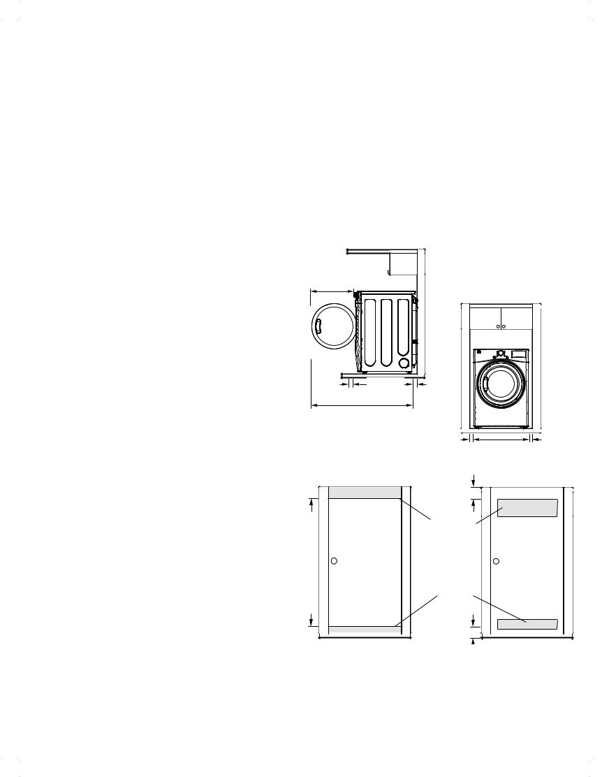
 CLEARANCES
•Most installations require a minimum 5 inch (12.7 cm) clearance behind the dryer for the exhaust ducting.
•Allow minimum clearances of at least 1 inch (2.5 cm) on the sides and back to minimize vibration and noise.
•Allowing additional clearance for installation and servicing is recommended.
•Be sure to allow for wall, door, or floor moldings that may increase the required clearances.
•Allow at least 22 ½ inches (57.3 cm) in front of the dryer to open the door.
Standard Installation – Side View |
|
|
|||
22 ½in. |
|
|
|
|
|
(57.3 cm) |
|
|
|
|
|
|
|
|
Standard Installation – Front View |
||
5 in. |
|
30 in. |
5 in. |
|
|
(12.7 cm) |
|
(12.7 cm) |
|
|
|
|
(76.5 cm) |
|
|
||
|
|
|
|
|
|
51 |
3 |
4 in. |
|
|
|
|
/ |
|
|
|
|
(130.5 cm) |
|
|
|
||
|
|
|
1 in. |
|
1 in. |
|
|
|
(2.5 cm) |
27 in. |
(2.5 cm) |
|
|
|
|
|
|
|
|
|
|
(68.6 cm) |
|
3" (7.6 cm)
Vent
48 sq. in.
(310 sq. cm. )
Vent
24 sq. in.
(155 sq. cm. )
3" (7.6 cm)
Additional instructions for closet installations:
The closet door must allow for su cient airflow. Refer to the diagram above for minimum vent opening requirements. A louvered door is also acceptable.
9
INSTALLATION INSTRUCTIONS
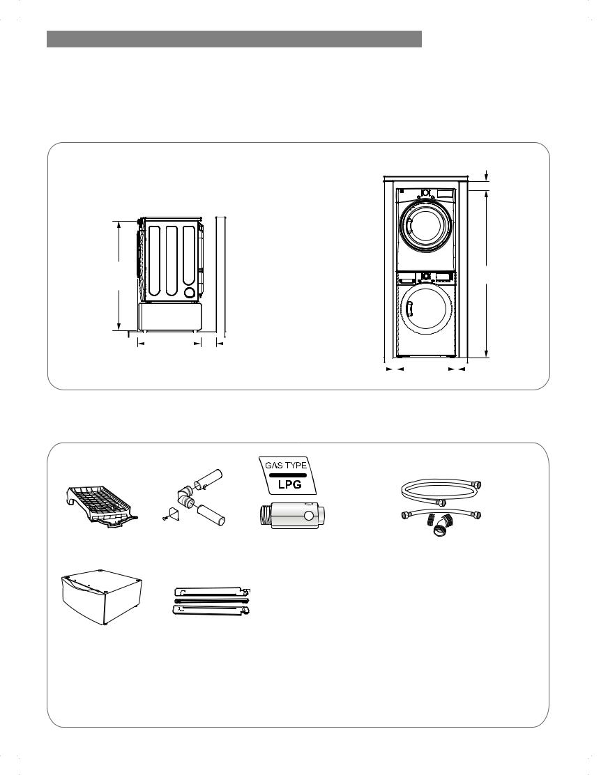
 INSTALLATION WITH OPTIONAL PEDESTAL BASE OR STACKING KIT
IMPORTANT: If you are installing your dryer using an optional pedestal base or stacking kit, refer to the instructions included with the accessory.
Required Dimensions for
Installation with Pedestal
53 in. |
(134.6 cm) |
 5 in. 30 in. (12.7 cm)
(76.5 cm)
Required Dimensions for
Installation with Stacking Kit
6 in. |
(15.2 cm) |
77 ½ in. |
(196.8 cm) |
1 in. |
|
|
|
|
|
|
|
|
|
|
|
|
1 in. |
|
|
|
|
|
|
|
|
|
|
|
|
||||
|
|
|
|
|
|
27 in. |
|
|
|
|||||
(2.5 cm) |
|
|
|
|
(2.5 cm) |
|||||||||
(68.6 cm) |
||||||||||||||
|
|
|
|
|
|
|
||||||||
 ACCESSORIES
Optional Accessories |
Required Accessories |
(sold separately) |
(sold separately) |
drying rack** |
side vent kit* |
|
|
LP conversion kit* |
|
|
connector* |
|
|
|
Hoses and Y |
||||||
No. 3751EL1001B |
Kit No. 26-49670 |
|
|
No. 26-17025 |
Kit No. 26-59029 |
|||
|
|
|
|
|
|
|
|
|
|
|
|
|
|
|
|
|
|
|
|
|
|
|
|
|
|
|
|
|
|
|
|
|
|
|
|
pedestal* |
|
stacking kit* |
* at Sears.com |
White = 51122 |
Chrome Look = 26-17013 |
** at SearsPartsDirect.com |
|
Metallic Silver = |
51123 |
|
|
Use the LP conversion kit for changing the dryer gas connections from natural gas (NG) to propane gas (LP). NOTE: Installation of the LP conversion kit must be performed by a qualified service technician.
10
 CONNECTING GAS DRYERS
GAS REQUIREMENTS (GAS MODELS ONLY)
 WARNING: To reduce the risk of fire, electric shock, or injury to persons when using this appliance, follow basic precautions, including
the following:
•Gas supply requirements: As shipped from the factory, this dryer is configured for use with natural gas (NG). It can be converted for use with propane (LP) gas. Gas pressure must not exceed 8 inches water column for (NG), or 13 inches water column for (LP).
•A qualified service or gas company technician must connect the dryer to the gas service. Failure to follow these instructions can result in fire, explosion, or death.
•Isolate the dryer from the gas supply system by closing its individual manual shuto valve during any pressure testing of the gas supply. Failure to do so can result in fire, explosion, or death.
•Supply line requirements: Your laundry room must have a rigid gas supply line to your dryer. In the United States, an individual manual shuto valve MUST be installed within at least 6 ft. (1.8 m) of the dryer, in accordance with the National Fuel Gas Code ANSI Z223.1 or Canadian gas installation code CSA B149.1. A ⅛ inch NPT pipe plug must be installed.
Failure to do so can result in fire, explosion, or death.
•If using a rigid pipe, the rigid pipe should be ½ inch IPS. If acceptable under local codes and ordinances and when acceptable to your gas supplier, ⅜ inch approved tubing may be used where lengths are less than 20 ft. (6.1 m). Larger tubing should be used for lengths in excess of 20 ft. (6.1 m). Failure to do so can result in fire, explosion, or death.
INSTALLATION INSTRUCTIONS
•Connect the dryer to the type of gas shown on the nameplate. Failure to do so can result in fire, explosion, or death.
•To prevent contamination of the gas valve, purge the gas supply of air and sediment before connecting the gas supply to the dryer. Before tightening the connection between the gas supply and the dryer, purge remaining air until the odor of gas is detected.
Failure to do so can result in fire, explosion, or death.
•DO NOT use an open flame to inspect for gas leaks. Use a noncorrosive leak detection fluid. Failure to do so can result in fire, explosion, or death.
•Use only a new AGAor CSA-certified gas supply line with flexible stainless steel connectors. Failure to do so can result in fire, explosion, or death.
•Securely tighten all gas connections. Failure to do so can result in fire, explosion, or death.
•Use Teflon tape or a pipe-joint compound that is insoluble in propane (LP) gas on all pipe threads.
Failure to do so can result in fire, explosion, or death.
•DO NOT attempt any disassembly of the dryer; disassembly requires the attention and tools of an authorized and qualified service technician or
company. Failure to follow this warning can result in fire, explosion, or death.
ELECTRICAL REQUIREMENTS FOR
GAS MODELS ONLY
•Do not, under any circumstances, cut or remove the third (ground) prong from the power cord. Failure to follow this warning can result in fire, explosion, or death.
•For personal safety, this dryer must be properly grounded. Failure to follow this warning can result in fire, explosion, or death.
•The power cord of this dryer is equipped with a 3-prong (grounding) plug which mates with a
standard 3-prong (grounding) wall outlet to minimize the possibility of electric shock hazard from this appliance. Failure to follow this warning can result in fire, explosion, or death.
•This dryer must be plugged into a 120-VAC, 60-Hz. grounded outlet protected by a 15-ampere fuse or circuit breaker. Failure to follow this warning can result in fire, explosion, or death.
•Where a standard 2-prong wall outlet is encountered, it is your personal responsibility and obligation to have it replaced with a properly grounded 3-prong wall outlet. Failure to follow this warning can result in fire, explosion, or death.
3-prong grounding type wall receptacle
Ensure proper ground exists before use.
3-prong grounding
plug
11

INSTALLATION INSTRUCTIONS
 CONNECTING GAS DRYERS (continued)
 WARNING: To reduce the risk of fire, electric shock, or injury to persons when using this appliance, follow basic precautions, including
the following:
•Installation and service must be performed by a qualified installer, service agency, or the gas supplier.
Failure to do so can result in fire, explosion, or death.
•Use only a new stainless steel flexible connector and a new AGA-certified connector. Failure to do so can result in fire, explosion, or death.
•A gas shuto valve must be installed within 6 ft. (1.8 m) of the dryer. Failure to do so can result in fire, explosion, or death.
•The dryer is configured for natural gas when shipped from the factory. Make sure that the dryer is equipped with the correct burner nozzle for the type of gas being used (natural gas or propane gas).
Failure to do so can result in fire, explosion, or death.
Connecting the Gas Supply
NOTE: This dryer is configured from the factory set for natural gas (NG). If dryer is to be used with propane (LP) gas, it must be converted by a qualified
service technician.
1Make sure that the gas supply to the laundry room is turned OFF and the dryer is unplugged. Confirm that the type of gas available in your laundry room is appropriate for the dryer.
2Remove the shipping cap from the gas fitting at the back of the dryer. Be careful not to damage the threads of the gas connector when removing the shipping cap.
3Connect the dryer to your laundry room’s gas supply using a new flexible stainless steel connector with a ⅜ inches NPT fitting.
NOTE: DO NOT use old connectors.
4Securely tighten all connections between the dryer and your laundry room’s gas supply.
5Turn on the gas supply.
6Check all pipe connections (both internal and external) for gas leaks with a noncorrosive leak-detection fluid.
7Proceed to Venting the Dryer.
•If necessary, the correct nozzle (for the LP nozzle kit, order part number D26-17025) should be installed by a qualified technician and the change should be noted on the dryer. Failure to do so can result in fire, explosion, or death.
•All connections must be in accordance with local codes and regulations. Failure to do so can result in fire, explosion, or death.
•Gas dryers MUST exhaust to the outdoors. Failure to do so can result in fire, explosion, or death.
⅜ in. NPT Gas |
⅛ in. NPT Pipe Plug |
|
|
Connection |
|
|
Gas Supply |
AGA/CSA-Certified |
Shutoff Valve |
Stainless Steel Flexible |
|
Connector |
|
High-Altitude Installations
The BTU rating of this dryer is AGA-certified for elevations below 10,000 feet.
If your gas dryer is being installed at an elevation above 10,000 feet, it must be derated by a qualified technician or gas supplier.
12

 CONNECTING ELECTRIC DRYERS ELECTRICAL REQUIREMENTS
 WARNING: To help prevent fire, electric shock, serious injury, or death, the wiring and grounding
must conform to the latest edition of the National Electrical Code, ANSI/NFPA 70 and all applicable local regulations. Please contact a qualified electrician to check your home’s wiring and fuses to ensure that your home has adequate electrical power to operate the dryer.
Special Electrical Requirements for Mobile or Manufactured Homes
 WARNING: To reduce the risk of fire, electric shock, or injury to persons when using this appliance, follow basic precautions, including the following:
•Any installation in a manufactured or mobile home must comply with the Manufactured Home
Construction and Safety Standards Title 24 CFR, Part 3280 or Standard CAN/CSA Z240 MH and local codes and ordinances.
•A 4-wire connection is required for all mobile and manufactured home installations, as well as all new construction after January 1, 1996. Failure to do so can result in fire, explosion, or death.
INSTALLATION INSTRUCTIONS
Electrical Requirements for Electric Models Only
 WARNING: To reduce the risk of fire, electric shock, or injury to persons when using this appliance, follow basic precautions, including
the following:
•This dryer must be connected to a grounded metal, permanent wiring system, or an equipment grounding conductor must be run with the circuit conductors and connected to the equipment grounding terminal or lead on the dryer. Failure to do so can result in fire, explosion, or death.
•The dryer has its own terminal block that must be connected to a separate 240 VAC, 60-Hertz, single phase circuit, fused at 30 amperes (the circuit must be fused on both sides of the line). ELECTRICAL SERVICE FOR THE DRYER SHOULD BE OF THE MAXIMUM RATE VOLTAGE LISTED ON THE NAMEPLATE. DO NOT CONNECT THE DRYER TO A 110-, 115-, OR 120-VOLT CIRCUIT. Failure to follow these instructions can result in fire, explosion, or death.
•If the branch circuit to the dryer is 15 ft. (4.5 m) or less in length, use UL (Underwriters Laboratories) listed No.-10 AWG wire (copper wire only), or as required by local codes. If over 15 ft. (4.50 m), use UL-listed No.-8 AWG wire (copper wire only), or as required by local codes. Allow su cient slack in the wiring so the dryer can be moved from its normal location when necessary. Failure to do so can result in fire, explosion, or death.
•The power cord (pigtail) connection between wall receptacle and dryer terminal block IS NOT supplied with the dryer. Type of pigtail and gauge of wire must conform to local codes and with instructions on the following pages. Failure to follow these instructions can result in fire, explosion, or death
•A 4-wire connection is required for all new construction after January 1, 1996. A 4-wire connection must be used where local codes do not permit grounding through the neutral wire. Failure to do so can result in fire, explosion, or death.
13

INSTALLATION INSTRUCTIONS
 CONNECTING ELECTRIC DRYERS (continued)
 WARNING:
Connect the power cord to the terminal block. Connect each power cord wire to the terminal block screw that has the same colored wire. For example, connect the black power cord wire to the terminal block screw with the black wire. Failure to follow these instructions may result in a short, overload, fire or death.
Grounding through the neutral wire is prohibited for:
(1) new branch-circuit installations, (2) mobile homes,
(3) recreational vehicles, and (4) areas where local codes prohibit grounding through the neutral wire.
Four-Wire Power Cord
• A 4-wire connection is required for all
mobile and manufactured home installations, as well as all new construction after January 1, 1996.
•A UL-listed strain relief is required.
•Use a 30-amp, 240-volt, 4-wire, UL-listed power cord with #10 AWG-minimum copper conductor and closed loop or forked terminals with upturned ends.
Terminal
Block
UL-Listed |
Strain Relief |
UL-Listed |
4 Wire |
Power |
Cord |
1Remove the terminal block access cover on the upper back of the dryer.
2Install a UL-listed strain relief into the power cord through-hole.
3Thread a 30-amp, 240-volt, 4-wire, UL-listed power cord with #10 AWG-minimum copper conductor through the strain relief.
Hot |
Neutral |
Hot |
(Black) |
(White) (Red) |
|
Green Ground Screw |
|
Neutral |
Green Wire of |
|
|
|
Grounding |
|
Power Cord |
|
Wire |
4Transfer the neutral grounding wire from behind the green ground screw to the center screw of the terminal block.
5Attach the two hot leads (black and red) of the power cord to the outer terminal block screws.
6Attach the power cord white neutral wire to the center screw of the terminal block.
7Attach the power cord ground wire to the green ground screw.
8TIGHTEN ALL SCREWS SECURELY.
9Reinstall the terminal block access cover.
Three-Wire Power Cord
• A 3-wire connection is NOT permitted on  new construction after January 1, 1996.
• A UL-listed strain relief is required.
•Use a 30-amp, 240-volt, 3-wire, UL-listed power cord with #10 AWG-minimum copper conductor and closed loop or forked terminals with upturned ends.
Terminal
Block
UL-Listed
Strain Relief
UL-Listed
3 Wire
Power
Cord
1Remove the terminal block access cover on the upper back of the dryer.
2Install a UL-listed strain relief into the power cord through-hole.
3Thread a 30-amp, 240-volt, 3-wire, UL-listed power cord with #10 AWG-minimum copper conductor through the strain relief.
Neutral |
|
|
Hot |
Grounding |
Hot |
Neutral |
|
Wire |
(Black) |
(White) |
(Red) |
Green Ground Screw 


External Ground Wire 
4Attach the two hot leads (black and red) of the power cord to the outer terminal block screws.
5Attach the power cord neutral (white) wire to the center terminal block screw.
6Connect the external ground (if required by local codes) to the green ground screw.
7TIGHTEN ALL SCREWS SECURELY.
8Reinstall the terminal block access cover.
14

INSTALLATION INSTRUCTIONS
 VENTING THE DRYER
IMPORTANT! CHECK YOUR EXHAUST SYSTEM FOR PROBLEMS
The most common cause of dryer problems is poor exhaust venting. Before installing your new dryer, check the items listed below to make sure you get the best possible performance. This can save you time and money by reducing cycle times and increasing energy e ciency.
•DIRTY OR DAMAGED EXHAUST DUCTS. Lint builds up in exhaust ducts over time. This decreases the airflow and makes the dryer work harder. Visually inspect your ducts from both ends and have them cleaned if they have not been cleaned recently.
•WRONG VENT MATERIAL. Check your vent to make sure it is rigid or semi-rigid metal ducting. If your venting is plastic or flexible foil, have it replaced before using the dryer.
•RESTRICTED OR DAMAGED VENT HOOD. Check your vent hood outside. It must be clean and free of lint buildup. Check the damper and make sure it opens fully and easily.
•EXCESSIVELY LONG VENT. Measure the length of your exhaust system and count the elbows. Use the chart below to see if your duct is too long. If it is too long, have the duct routed to another location that is within the venting guidelines.
•DO NOT USE PLASTIC OR FOIL VENTING. The transition duct from your dryer to the wall must be rigid or semi-rigid metal ducting. If your old transition duct is plastic or foil, REPLACE IT with semi-rigid metal ducting.
Using the DUCT LENGTH CHART (below)
1Find your vent hood type in the chart below.
2Select the row that matches the number of elbows in your dryer duct run.
3Look to the right of the elbow number for the maximum duct length for your installation. Longer duct length will result in reduced drying performance, longer dry times and increased energy consumption. Extremely long ducts can even shorten the life of the dryer.
DO NOT exceed the maximum length for the vent hood type and number of elbows used.
|
|
Vent Hood Type |
Number of 90° |
Maximum length of 4" (10.2 cm ) |
||||||||||||
|
|
Elbows |
diameter rigid metal duct |
|||||||||||||
|
|
|
|
|
|
|
|
|
|
|
|
|
|
|
||
|
|
Recommended |
0 |
65 feet (19.8 m) |
||||||||||||
|
|
|
|
|
|
|
|
|
|
|
|
|
|
|
|
|
|
|
|
|
|
|
|
|
|
|
|
|
|
|
1 |
55 feet (16.8 m) |
|
|
|
|
|
|
|
|
|
|
|
|
|
|
|
|
|
|
|
|
|
|
|
|
|
|
|
|
|
|
|
|
2 |
47 feet (14.3 m) |
|
|
|
|
|
|
|
|
|
|
|
|
|
|
|
|||
|
|
|
|
|
|
|
|
|
|
|
|
|
|
|
|
|
|
|
|
|
|
|
|
|
|
|
|
|
|
|
3 |
36 feet (11.0 m ) |
|
|
|
|
|
|
|
|
|
|
|
|
|
|
|
|||
4" |
|
|
4" |
|
|
|||||||||||
|
|
|
|
|
|
|||||||||||
4 |
28 feet (8.5 m) |
|||||||||||||||
(10.2 cm ) |
|
|
|
|
(10.2 cm ) |
|||||||||||
|
|
|
|
|
|
|
|
|
|
|
|
|
|
|
|
|
Only for Short-Run Installations |
0 |
55 feet (16.8 m) |
||||||||||||||
|
|
|||||||||||||||
|
|
|
|
|
|
|
|
|
|
|
|
|
|
1 |
47 feet (14.3 m) |
|
|
|
|
|
|
|
|
|
|
|
|
|
|
|
|
|
|
|
|
|
|
|
|
|
|
|
|
|
|
|
|
2 |
41 feet (12.5 m) |
|
|
|
|
|
|
|
|
|
|
|
|
|
|
|
|||
|
|
|
|
|
|
|
|
|
|
|
|
|
|
|||
|
|
|
|
|
|
|
|
|
|
|
|
|
|
|
|
|
|
|
|
|
|
|
|
|
|
|
|
|
|
|
3 |
30 feet (9.1 m) |
|
|
|
|
|
|
|
|
|
|
|
|
|
|
|
|||
|
|
|
|
|
21/2" |
|
|
|
|
|
||||||
|
|
|
|
|
|
|
|
|
|
|
|
|||||
|
|
|
|
|
|
|
||||||||||
|
|
|
|
|
(6.35 cm ) |
4 |
22 feet (6.7 m) |
|||||||||
|
|
|
|
|
|
|
|
|
|
|
|
|
|
|||
|
|
|
|
|
|
|
|
|
|
|
|
|
|
|
|
|
NOTE:
•Deduct 6 ft. (1.8 m) for each additional elbow. Using more than four 90° elbows is not recommended.
•Treat two 45° elbows as one 90° elbow.
•One elbow of 45° or less by itself can be ignored.
15
 Loading...