

Page 1
Use & Care Guide
Model: 796.8128#, 796.9128#, 796.8118#, 796.9118#
Kenmore
Dryer
# = color number
MFL67731010
Sears Brands Management Corporation
Hoff man Estates, IL 60179 U.S.A.
www.kenmore.com
®
®
Page 2

TABLE OF CONTENTS
PROTECTION AGREEMENTS
IMPORTANT SAFETY INSTRUCTIONS ....................3-6
GROUNDING REQUIREMENTS ...................................
FEATURES AND BENEFITS
Key Parts and Components ........................................7
INSTALLATION INSTRUCTIONS
Key Dimensions and Specifi cations
Location Requirements ................................................8
Choose the Proper Location ....................................... 8
Clearances ....................................................................8
Installation with Optional Pedestal Base
or Stacking Kit .............................................................9
Optional Accessories ..................................................9
Gas Dryers .............................................................10-11
Gas Requirements (Gas Models Only) .............. 10
Electrical Requirements for Gas Models Only ..... 10
Connecting the Gas Supply ................................. 11
Electric Dryers ......................................................12-13
Electrical Requirements ....................................... 12
Connecting Electric Dryers ................................. 13
Venting the Dryer .................................................14-15
Leveling the Dryer ..................................................... 16
Reversing the Door Swing ........................................ 16
Final Installation Check ............................................ 17
HOW TO USE
Control Panel Features ............................................. 18
Operating the Dryer ................................................. 19
Cycle Guide ......................................................... 20-21
Sorting Loads .............................................................22
Loading the Dryer .....................................................22
Time and Status Display ..........................................23
Cycle Modifi er Buttons ............................................ 24
Cycle Options and Special Features ......................25
Wrinkle Guard ....................................................25
Control Lock ........................................................25
My Cycle ..............................................................25
Damp Dry Signal .................................................25
USER MAINTENANCE INSTRUCTIONS
Regular Cleaning ..................................................... 26
Cleaning the Exterior ......................................... 26
Cleaning the Interior .......................................... 26
Cleaning Around and Under the Dryer ........... 26
Cleaning the Lint Filter ...................................... 26
Maintaining the Exhaust System .............................27
KENMORE CONNECT ................................................. 28
TROUBLESHOOTING GUIDE
Before Calling for Service ................................. 29-31
ARRANTY ................................................................... 32
W
SERVICE .......................................................... Back Cover
PRODUCT RECORD
In the space below, record the date of purchase, model,
and serial number of your product. You will fi nd the
model and serial number printed on an identifi cation
plate located inside the dryer door. Have these items of
information available whenever you contact Sears
concerning your product.
Model No
Date of Purchase
Serial No.
Save these instructions and your sales receipt for future
reference.
.
..........................8
4
Master Protection Agreements
Congratulations on making a smart purchase. Your new
enmore
K
years of dependable operation. But like all products,
it may require preventive maintenance or repair from
time to time. That’s when having a Master Protection
Agreement can save you money and aggravation.
The Master Protection Agreement also helps extend the
life of your new product. Here’s what the Agreement*
includes:
• Parts and labor needed to help keep products
operating properly under normal use
Our coverage goes well beyond the product warranty.
No deductible, no functional failure excluded from
coverage – real protection.
• Expert service b
authorized Se
someone you can trust will be working on your product.
• Unlimited service calls and nationwide service, as often
as you want us, whenever you want us.
• “No-lemon” guarantee – r
covered product if four or more product failures occur
within 12 months.
• Product replacement if y
be fi xe
• Annual Preventive Maintenance Check at y
– no extra charge.
• Fast help by phone – w
Phone support from a Sears representative on all
pr
Power surge protection against electrical damage due
•
power fl uctuations.
• $250 food loss protection annually for an
spoilage that is the result of mechanical failure of any
co
• Rental reimbursement if repair of your covered
product takes longer than promised.
• 25% discount off
repair service and related installed parts.
Once you purchase the Agreement, a simple phone call
is all that it tak
call at any time day or night or schedule a service
appointment online.
The Master Protection Agreement is a risk-free purchase.
If you cancel for any reason during the product warranty
period, we will provide a full refund, or a prorated refund
anytime after the product warranty period expires.
Purchase your Master Protection Agreement today!
Some limitations and exclusions apply.
For prices and additional information in the U.S.A.
call 1-800-827-6655.
*Coverage in Canada varies on some items.
For full details call Sears Canada at 1-800-361-6665.
Sears Installation Service
For Sears professional installation of home appliances,
garage door openers, water heaters, and other major
home items, in the U.S.A. or Canada call:
1-800-4-MY-HOME
2
®
product is designed and manufactured for
, not just defects.
y a force of more than 10,000
ars service technicians, which means
eplacement of your
our covered product can not
d.
our request
e call it Rapid Resolution.
oducts. Think of us as a “talking owner’s manual.”
y food
vered refrigerator or freezer.
the regular price of any non-covered
es for you to schedule service. You can
®
.
to
Page 3
IMPORTANT SAFETY INSTRUCTIONS
READ ALL INSTRUCTIONS BEFORE USE
Your safety and the safety of others is very important.
We have provided many important safety messages in this manual and on your appliance. Always read and
obey all safety messages.
This is the safety alert symbol.
This symbol alerts you to potential hazards that can kill or hurt you and others.
All safety messages will follow the safety alert symbol and either the word DANGER or WARNING.
These words mean:
DANGER:
Indicates a hazardous situation which, if not avoided, could result in death or serious injury.
WARNING:
CAUTION:
All safety messages will tell you what the potential hazard is, tell you how to reduce the chance of injury, and
tell you what can happen if the instructions are not followed.
For your safety, the information in this manual must be followed to
WARNING:
minimize the risk of fi re or explosion, electric shock, or to prevent property damage, personal injury,
or loss of life.
• Do not install a clothes dryer with fl exible plastic venting materials. If a fl exible metal (foil type) duct is installed,
it must be of a specifi c type identifi ed by the appliance manufacturer as suitable for use with clothes dryers.
Flexible venting materials are known to collapse, be easily crushed, and trap lint. These conditions will obstruct
clothes dryer airfl ow and increase the risk of fi re.
• Do not store or use gasoline or other fl ammable vapors and liquids in the vicinity of this appliance or any
other appliances.
• Installation and service must be performed by a qualifi ed installer, service agency, or the gas supplier.
• Install the clothes dryer according to the manufacturer’s instructions and local codes.
• Save these instructions.
Indicates a hazardous situation which, if not avoided, will result in death or serious injury.
Indicates a hazardous situation which, if not avoided, could result in minor or
moderate injury.
WHAT TO DO IF YOU SMELL GAS:
1. Do not try to light a match or cigarette, or turn on any gas or electrical appliance.
2. Do not touch any electrical switches. Do not use any phones in your building.
3. Clear the room, building, or area of all occupants.
4. Immediately call your gas supplier from a neighbor’s phone. Carefully follow the gas supplier’s instructions.
5. If you cannot reach your gas supplier, call the fi r
e department.
SAVE THESE INSTRUCTIONS
3
Page 4

IMPORTANT SAFETY INSTRUCTIONS
BASIC SAFETY PRECAUTIONS
To reduce the risk of fi re, electric shock, or injury to persons when using this appliance,
WARNING:
follow basic precautions, including the following:
• Read all instructions before using the dryer.
• Before use, the dryer must be properly installed, as
described in this manual.
• Do not place items exposed to cooking oils in your
dryer. Items contaminated with cooking oils may
contribute to a chemical reaction that could cause a
load to catch fi re.
• Do not dry articles that have been previously cleaned
in, washed in, soaked in, or spotted with gasoline,
dry-cleaning solvents, or other fl ammable or explosive
substances, as they give off vapors that could ignite
or explode.
• Do not reach into the dryer if the drum or any other
part is moving.
• Do not repair or replace any part of the dryer or
attempt any servicing unless specifi cally recommended
in this Use and Care Guide or in published user-repair
instructions that you understand and have the skills to
carry out.
• Do not tamper with controls.
• Before the dryer is removed from service or discarded,
remove the door to the drying compartment.
• Do not allow children to play on or in the dryer. Close
supervision of children is necessary when the dryer is
used near children.
• Do not use fabric softeners or products to eliminate
static unless recommended by the manufacturer of the
fabric softener or product.
• Do not use heat to dry articles containing foam rubber
or similarly textured rubber-like materials.
• Keep the area around the exhaust opening and
adjacent surrounding areas free from the accumulation
of lint, dust, and dirt.
• The interior of the dryer and exhaust vent should be
cleaned periodically by qualifi ed service personnel.
• Do not install or store the dryer where it will be
exposed to the weather.
• Always check the inside of the dryer for
foreign objects.
• Clean the lint fi lter before or after each load.
• Gas appliances can cause minor exposure to four
potentially harmful substances, namely benzene,
carbon monoxide, formaldehyde, and soot, caused
primarily by the incomplete combustion of natural
gas or LP fuels. Properly adjusted dryers will minimize
incomplete combustion. Exposure to these substances
can be minimized further by properly venting the dryer
to the outdoors.
GROUNDING REQUIREMENTS
This appliance must be grounded. In the event of
malfunction or breakdown, grounding will reduce
the risk of electric shock by providing a path of least
resistance for electric current. This appliance must be
equipped with a cord having an equipment-grounding
conductor and a grounding plug. The plug must be
plugged into an appropriate outlet that is properly
installed and grounded in accordance with all local
codes and ordinances.
WARNING:
equipment-grounding conductor can result in a risk of
electric shock. Check with a qualifi ed electrician or
service person if you are in doubt as to whether the
appliance is properly grounded. Do not modify the plug
provided with the appliance. If it will not fi t the outlet,
have a proper outlet installed by a qualifi ed electrician.
This appliance must be connected to a grounded metal,
permanent wiring system or an equipment grounding
conductor must be run with the circuit conductors and
connected to the equipment grounding terminal or lead
on the appliance. Electrical shock can result if the dryer
is not properly grounded.
Improper connection of the
4
Page 5

IMPORTANT SAFETY INSTRUCTIONS
SAFETY INSTRUCTIONS FOR INSTALLATION
To reduce the risk of fi re, electric shock, or injury to persons when using this appliance,
WARNING:
follow basic precautions, including the following:
• Properly ground dryer to conform with all governing
odes and ordinances. Follow details in the installation
c
instructions. Electrical shock can result if the dryer is not
properly grounded.
• Before use, the dryer must be properly installed as
described in this manual. Electrical shock can result if
the dryer is not properly grounded.
• Install and store the dryer where it will not be exposed
to temperatures below freezing or exposed to
the weather.
• All repairs and servicing must be performed by an
authorized service technician unless specifi cally
recommended in this Use & Care Guide. Use only
authorized factory parts. Failure to follow this warning
can cause serious injury, fi re, electrical shock, or death.
• To reduce the risk of electrical shock, do not install the
dryer in humid spaces. Failure to follow this warning
can cause serious injury, fi re, electrical shock, or death.
• Connect to a properly rated, protected, and sized
power circuit to avoid electrical overload. Improper
power circuits can melt, creating risk of electrical shock
and/or fi re hazard.
• Remove all packing items and dispose of all shipping
materials properly. Failure to do so can result in fi re,
explosion, burns, or death.
• Place dryer at least 18 inches above the fl oor for a
garage installation. Failure to do so can result in fi re,
explosion, burns, or death.
• Keep all packaging from children. Packaging material
can be dangerous for children. There is a risk of
suff ocation.
• Do not install near items that produce heat or open
fl ame such as stoves or cooking ovens. Failure to follow
this warning can cause product deformation, smoke and
fi re.
• Do not place candles or cigarettes on top of the
product. Failure to follow this warning can cause
product deformation, smoke and fi re.
• Remove all protective vinyl fi lm from the product.
Failure to do so can cause product deformation, smoke
and fi re.
Exhaust/Ducting:
• Gas dryers MUST be exhausted to the outside. Failure
to follow these instructions can result in fi re or death.
• The dryer exhaust system must be exhausted to the
outside of the dwelling. If the dryer is not exhausted
outdoors, some fi ne lint and large amounts of
moisture will be expelled into the laundry area. An
accumulation of lint in any area of the home can
create a health and fi re hazard.
• Use only rigid metal or fl exible metal 4 inch diameter
duct inside the dryer cabinet or for exhausting to the
outside. Use of plastic or other combustible ductwork
can cause a fi re. Punctured ductwork can cause a fi re
if it collapses or becomes otherwise restricted in use or
during installation.
• Ductwork is not provided with the dryer, and you
should obtain the necessary ductwork locally. The end
cap should have hinged dampers to prevent backdraft
when the dryer is not in use. Failure to follow these
instructions can result in fi re or death.
• The exhaust duct must be 4 inches (10.2 cm) in
diameter with no obstructions. The exhaust duct
should be kept as short as possible. Make sure to
an any old ducts before installing your new dryer.
cle
Failure to follow these instructions can result in fi re or
death.
• Rigid or semi rigid metal ducting is recommended
for use between the dryer and the wall. In special
installations when it is impossible to make a
connection with the above recommendations, a UL
listed fl exible metal transition duct may be used
between the dryer and wall connection only. The
use of this ducting will aff ect drying time. Failure to
follow these instructions can result in fi re or death.
• DO NOT use sheet metal screws or other fasteners
which extend into the duct that could catch lint and
reduce the effi ciency of the exhaust system. Secure
all joints with duct tape. For complete details, follow
the Installation Instructions. Failure to follow these
instructions can result in fi re or death.
5
Page 6

IMPORTANT SAFETY INSTRUCTIONS
To reduce the risk of fi re, electric shock, or injury to persons when using this appliance,
WARNING:
follow basic precautions, including the following:
SAFETY INSTRUCTIONS FOR CONNECTING ELECTRICITY
To reduce the risk of fi re, electric shock, or injury to persons when using this appliance,
WARNING:
follow basic precautions, including the following:
• Do not, under any circumstances, cut or remove
the gr
ound prong from the power cord. To prevent
personal injury or damage to the dryer, the electrical
power cord must be plugged into a properly
grounded outlet.
• For personal safety, this dryer must be properly
grounded. Failure to do so can result in electrical
shock or injury.
• Refer to the installation instructions in this manual
for specifi c electrical requirements for your model.
Failure to follow these instructions can create an
electrical shock hazard and/or a fi re hazard.
• This dryer must be plugged into a properly grounded
outlet. Electrical shock can result if the dryer is not
properly grounded. Have the wall outlet and circuit
checked by a qualifi ed electrician to make sure the
outlet is properly grounded. Failure to follow these
instructions can create an electrical shock hazard
and/or a fi re hazard.
• The dryer should always be plugged into its own
individual electrical outlet which has a voltage rating
that matches the rating plate. This provides the best
performance and also prevents overloading house
wiring circuits which could cause a fi re hazard from
overheated wires.
• Never unplug your dryer by pulling on the power
cord. Always grip the plug fi rmly and pull straight
out from the outlet. The power cord can be damaged,
resulting in a risk of fi re and electrical shock.
• Repair or replace immediately all power cords that
have become frayed or otherwise damaged. Do not
use a cord that shows cracks or abrasion damage
along its length or at either end. The power cord can
melt, creating electrical shock and/or fi re hazard.
• When installing or moving the dryer, be careful not
to pinch, crush, or damage the power cord. This will
prevent injury and prevent damage to the dryer from
fi re and electrical shock.
SAVE THESE INSTRUCTIONS
6
Page 7
FEATURES AND BENEFITS
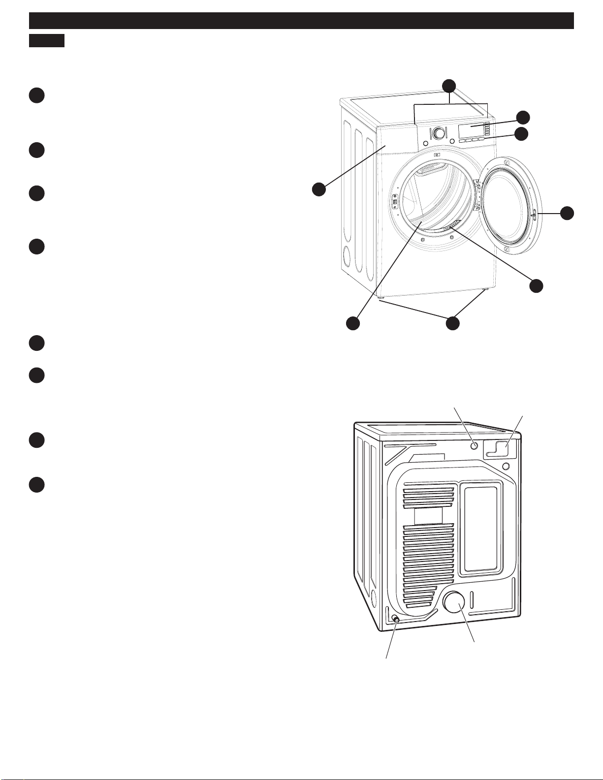
KEY PARTS AND COMPONENTS
There are several important components that are
eferenced in this manual.
r
A
EASY-TO-USE CONTROL PANEL
Rotate the cycle selector knob to select the desired
dry cycle. Add cycle options or adjust settings with
the touch of a button.
TIME AND STATUS DISPLAY
B
The easy-to-read LED display shows cycle status
and estimated time remaining.
A
B
C
CYCLE MODIFIERS
C
Adjust the cycle settings such as temperature and
dry level with the touch of a button.
NOTE: Not all settings are available for all cycles.
D
CHECK VENT
(Duct Blockage Sensing System)
The Check Vent (Duct Blockage Sensing System)
detects and alerts you to blockages in the exhaust
system that reduce airfl ow from the dryer.
Maintaining clean exhaust system ducts improves
operating effi ciency and helps minimize service
calls, saving you money.
E
ULTRA-CAPACITY DRUM
The ultra-large drum off ers superior durability.
F
EASY-ACCESS REVERSIBLE DOOR
The wide-opening, see-through glass door
provides easy access for loading and unloading.
Door swing can be reversed to adjust for
installation location.
G
FRONT-MOUNT LINT FILTER
The front-mount lint fi lter allows for easy access
and cleaning between loads.
D
F
G
HE
Power Cord
Location
(Gas Models)
Terminal Block
Access Panel
(Electric Models)
H
LEVELING FEET
Four leveling feet (two in front, and two in back)
adjust to improve dryer stability on uneven fl oors.
Gas Connection
Location
(Gas Models)
Rear of Dryer
7
Exhaust Duct
Outlet
Page 8
INSTALLATION INSTRUCTIONS
KEY DIMENSIONS AND SPECIFICATIONS
Description Dryer (Gas and Electric)
Electrical Requirements Refer to the rating label
Gas Requirements* NG: 4–10.5 inches WC (Water Column)
Gas Requirements* LP: 8–13 inches WC
Dimensions 27 in. (W) X 30
68.6 cm (W) X 76.7 cm (D) X 96.5 cm (H), 130 cm (D with door open)
Net Weight Electric : 147 lb. (66.7 kg) Gas : 150.5 lb. (68.3 kg)
Drying Capacity IEC 7.3 cu. ft.
*Gas Models Only
1/4
in. (D) X 38 in. (H), 51 3/16 in. (D with door open)
LOCATION REQUIREMENTS
IMPORTANT: Read all installation instructions
completely before installing and operating your dryer.
It is important that you review this entire manual before
installing and using your dryer. It contains detailed
instructions concerning electrical connections, gas
connections and exhaust requirements.
CHOOSE THE PROPER LOCATION
• Store and install the dryer where it will not be exposed
to temperatures below freezing or exposed to outdoor
weather conditions.
• Choose a location with a solid, level fl oor.
• If the dryer is being installed in a garage, place the
dryer at least 18 inches (45.7cm) above the fl oor.
• Properly ground the dryer to conform with all
governing codes and ordinances.
• To reduce the risk of electric shock, do not install the
dryer in damp or wet locations.
IMPORTANT: If you are installing your dryer in a
manufactured or mobile home, please refer to the
Special Electrical Requirements for Mobile or
Manufactured Homes section.
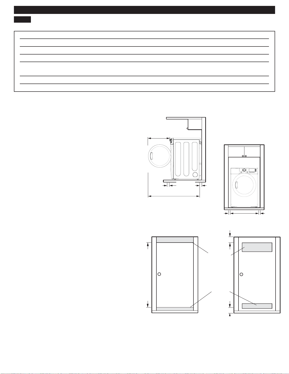
CLEARANCES
• Most installations require a minimum 5 ½ inch (14 cm)
clearance behind the dryer for the exhaust ducting.
• Allow minimum clearances of at least 1 inch (2.5 cm)
on the sides and back to minimize vibration and noise.
• Allowing additional clearance for installation and
servicing is recommended.
• Be sure to allow for wall, door, or fl oor moldings that
may increase the required clearances.
• Allow at least 21 inches (53.3 cm) in front of the dryer
to open the door.
Standard Installation – Side View
22 1/2 in.
(57.3 cm)
(10 cm)
30 1/4 in.
(76.7 cm)
52 ¼ in.
(132.7 cm)
Standard Installation – Front View
4 in.
(10 cm)
1 in.
(2.5 cm)
3"
(7.6 cm)
Vent
48 sq. in.
(310 sq. cm.)
Vent
24 sq. in.
(155 sq. cm.
3"
(7.6 cm)
27 in.
(68.6 cm)
)
1 in.
(2.5 cm)
Additional instructions for closet installations:
The closet door must allow for suffi cient airfl
diagram above for minimum vent opening requirements. A
louvered door is also acceptable.
8
ow. Refer to the
Page 9
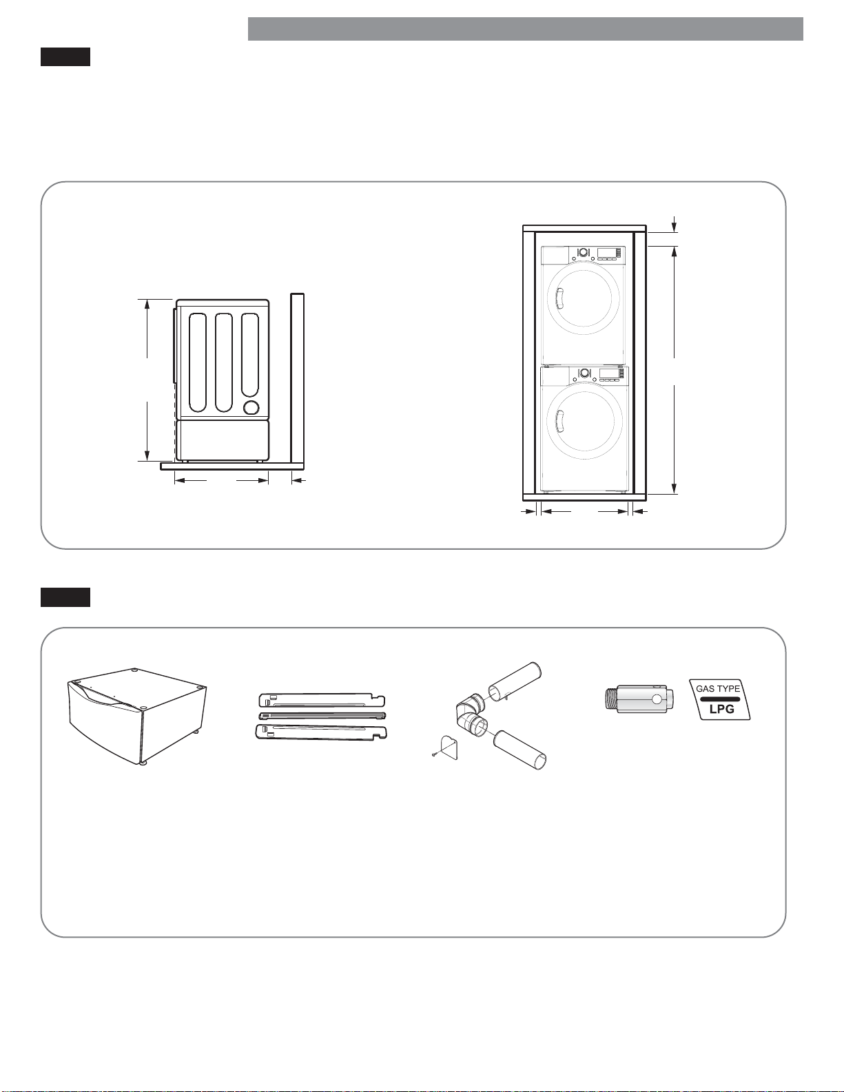
INSTALLATION WITH OPTIONAL PEDESTAL BASE OR STACKING KIT
IMPORTANT: If you are installing your dryer using
an optional pedestal base or stacking kit, refer to the
instructions included with the accessory.
INSTALLATION INSTRUCTIONS
Required Dimensions for
Installation with Pedestal
52 ½ in.
(133.4 cm)
30 1/4 in.
(76.7 cm)
(10 cm)
4 in.
Required Dimensions for
Installation with Stacking Kit
1 in.
(2.5 cm)
27 in.
(68.6 cm)
6 in.
(15.2 cm)
77 ⅞ in.
(198 cm)
1 in.
(2.5 cm)
OPTIONAL ACCESSORIES
Use a pedestal to make
laundry easier to reach.
White = 796.51022
Ginger = 796.51028
Chili Pepper = 796.51029
Use the stacking kit to
mount the dryer on top of
the washer to save fl oor
space.
Chrome = D26 17013
Use the side vent kit
for venting directly to
either side or to the
bottom. Gas dryers
can only vent to
the left.
Kit # D26-49670
Use the LP conversion kit
for changing the dryer gas
connections from natural
gas (NG) to propane gas (LP).
Part No. 383EEL3002D
NOTE: Installation of the
LP conversion kit must be
performed by a qualifi ed
service technician.
9
Page 10
INSTALLATION INSTRUCTIONS
GAS DRYERS
GAS REQUIREMENTS (GAS MODELS ONLY)
WARNING:
To reduce the risk of fi re,
electric shock, or injury to persons when using this
appliance, follow basic precautions, including
the following:
• Gas supply requirements: As shipped from the
factory, this dryer is confi gured for use with natural
gas (NG). It can be converted for use with propane
(LP) gas. Gas pressure must not exceed 8 inches
water column for (NG), or 13 inches water column for
(LP).
• A qualifi ed service or gas company technician must
connect the dryer to the gas service. Failure to follow
these instructions can result in fi re, explosion, or death.
• Isolate the dryer from the gas supply system by
closing its individual manual shutoff valve during any
pressure testing of the gas supply. Failure to do so can
result in fi re, explosion, or death.
• Supply line requirements: Your laundry room must
have a rigid gas supply line to your dryer. In the
United States, an individual manual shutoff valve
MUST be installed within at least 6 ft. (1.8 m) of the
dryer, in accordance with the National Fuel Gas Code
ANSI Z223.1 or Canadian gas installation code CSA
B149.1. A ⅛ inch NPT pipe plug must be installed.
Failure to do so can result in fi re, explosion, or death.
• If using a rigid pipe, the rigid pipe should be ½ inch
IPS. If acceptable under local codes and ordinances
and when acceptable to your gas supplier, ⅜ inch
approved tubing may be used where lengths are less
than 20 ft. (6.1 m). Larger tubing should be used for
lengths in excess of 20 ft. (6.1 m). Failure to do so can
result in fi re, explosion, or death.
• Connect the dryer to the type of gas shown on
the nameplate. Failure to do so can result in fi re,
explosion, or death.
• To prevent contamination of the gas valve, purge the
gas supply of air and sediment before connecting
the gas supply to the dryer. Before tightening the
connection between the gas supply and the dryer,
purge remaining air until the odor of gas is detected.
Failure to do so can result in fi re, explosion, or death.
• DO NOT use an open fl ame to inspect for gas leaks.
Use a noncorrosive leak detection fl uid. Failure to do
so can result in fi re, explosion, or death.
• Use only a new AGA- or CSA-certifi ed gas supply
line with fl exible stainless steel connectors. Failure to
do so can result in fi re, explosion, or death.
• Securely tighten all gas connections. Failure to do so
can result in fi re, explosion, or death.
• Use Tefl on tape or a pipe-joint compound that is
insoluble in propane (LP) gas on all pipe threads.
Failure to do so can result in fi re, explosion,
or death.
• DO NOT attempt any disassembly of the dryer;
disassembly requires the attention and tools of
an authorized and qualifi ed service technician or
company. Failure to follow this warning can result in fi re,
explosion, or death.
ELECTRICAL REQUIREMENTS FOR
GAS MODELS ONLY
• Do not, under any circumstances, cut or remove the
third (ground) prong from the power cord. Failure
to follow this warning can result in fi re, explosion, or
death.
• For personal safety, this dryer must be properly
grounded. Failure to follow this warning can result in
fi re, explosion, or death.
• The power cord of this dryer is equipped with
a 3-prong (grounding) plug which mates with a
standard 3-prong (grounding) wall outlet to minimize
the possibility of electric shock hazard from this
appliance. Failure to follow this warning can result in
fi re, explosion, or death.
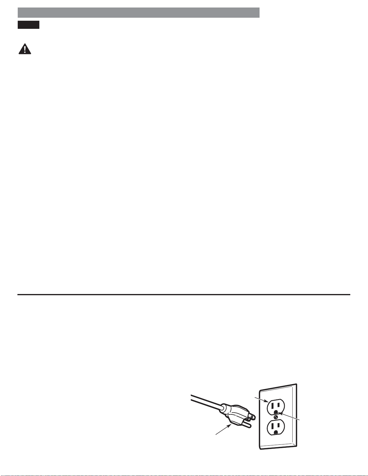
• This dryer must be plugged into a 120-VAC, 60-Hz.
grounded outlet protected by a 15-ampere fuse or
circuit breaker. Failure to follow this warning can result
in fi re, explosion, or death.
• Where a standard 2-prong wall outlet is encountered,
it is your personal responsibility and obligation to
have it replaced with a properly grounded 3-prong
wall outlet. Failure to follow this warning can result in
fi re, explosion, or death.
3-prong
grounding
type wall
receptacle
Ensure proper
ground exists
before use.
3-prong
grounding
plug
10
Page 11
3
GAS DRYERS (continued)
INSTALLATION INSTRUCTIONS
To reduce the risk of fi re
WARNING:
electric shock, or injury to persons when using this
appliance, follow basic precautions, including
the following:
• Installation and service must be performed by a
qualifi ed installer, service agency, or the gas supplier.
Failure to do so can result in fi re, explosion, or death.
• Use only a new stainless steel fl exible connector and
a new AGA-certifi ed connector. Failure to do so can
result in fi re, explosion, or death.
• A gas shutoff valve must be installed within 6 ft.
(1.8 m) of the dryer. Failure to do so can result in fi re,
explosion, or death.
• The dryer is confi gured for natural gas when
shipped from the factory. Make sure that the dryer
is equipped with the correct burner nozzle for the
type of gas being used (natural gas or propane gas).
Failure to do so can result in fi re, explosion, or death.
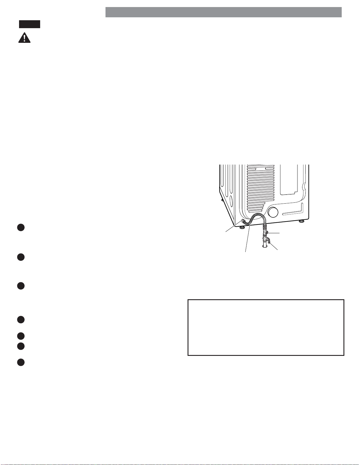
CONNECTING THE GAS SUPPLY
NOTE: This dryer is confi gured from the factory set for
natural gas (NG). If dryer is to be used with propane
(LP) gas, it must be converted by a qualifi ed
service technician.
,
• If necessary, the correct nozzle (for the LP nozzle kit,
order part number 383EEL3002D) should be installed
by a qualifi ed technician and the change should be
noted on the dryer. Failure to do so can result in fi re,
explosion, or death.
• All connections must be in accordance with local
codes and regulations. Failure to do so can result in
fi re, explosion, or death.
• Gas dryers MUST exhaust to the outdoors. Failure to do
so can result in fi re, explosion, or death.
1
Make sure that the gas supply to the laundry room is
d OFF and the dryer is unplugged. Confi rm that
turne
the type of gas available in your laundry room is
appropriate for the dryer.
2
Remove the shipping cap from the gas fi tting at the
back of the dryer. Be careful not to damage the
threads of the gas connector when removing the
shipping cap.
3
Connect the dryer to your laundry room’s gas supply
using a new fl exible stainless steel connector with a ⅜
inches NPT fi tting.
NOTE: DO NOT use old connectors.
4
Securely tighten all connections between the dryer
and your laundry room’s gas supply.
5
Turn on the gas supply.
6
Check all pipe connections (both internal and external)
for gas leaks with a noncorrosive leak-detection fl uid.
7
Proceed to Venting the Dryer.
1/8" NPT Pipe Plug
⅜ in. NPT Gas
/8" NPT Gas
Connection
Connection
AGA/CSA-Certified
AGA/CSA-Certified
Stainless Steel Flexible
Stainless Steel
Connector
Flexible Connector
High-Altitude Installations
The BTU rating of this dryer is AGA-certifi ed for
elevations below 10,000 feet.
If your gas dryer is being installed at an elevation
above 10,000 feet, it must be derated by a qualifi ed
technician or gas supplier.
⅛ in. NPT Pipe Plug
Gas Supply
Gas Supply
Shutoff Valve
Shutoff Valve
11
Page 12
INSTALLATION INSTRUCTIONS
ELECTRIC DRYERS
ELECTRICAL REQUIREMENTS
To help prevent fi re,
WARNING:
electrical shock, serious injury, or death, the wiring
and grounding must conform to the latest edition of
the National Electrical Code, ANSI/NFPA 70 and all
applicable local regulations. Please contact a qualifi ed
electrician to check your home’s wiring and fuses to
ensure that your home has adequate electrical power to
operate the dryer.
Special Electrical Requirements for Mobile
or Manufactured Homes
Electrical Requirements for Electric Models Only
WARNING:
To reduce the risk of
fi re, electric shock, or injury to persons when using this
appliance, follow basic precautions, including
the following:
• This dryer must be connected to a grounded metal,
permanent wiring system, or an equipment grounding
conductor must be run with the circuit conductors and
connected to the equipment grounding terminal or
lead on the dryer. Failure to do so can result in fi re,
explosion, or death.
WARNING:
To reduce the risk of fi re,
electric shock, or injury to persons when using this
appliance, follow basic precautions, including the
following:
• Any installation in a manufactured or mobile
home must comply with the Manufactured Home
Construction and Safety Standards Title 24 CFR, Part
3280 or Standard CAN/CSA Z240 MH and local codes
and ordinances.
• A 4-wire connection is required for all mobile and
manufactured home installations, as well as all new
construction after January 1, 1996. Failure to do so
can result in fi re, explosion, or death.
• The dryer has its own terminal block that must be
connected to a separate 240 VAC, 60-Hertz, single
phase circuit, fused at 30 amperes (the circuit must be
fused on both sides of the line). ELECTRICAL SERVICE
FOR THE DRYER SHOULD BE OF THE MAXIMUM
RATE VOLTAGE LISTED ON THE NAMEPLATE. DO
NOT CONNECT DRYER TO 110-, 115-, OR 120-VOLT
CIRCUIT. Failure to follow these instructions can result
in fi re, explosion, or death.
• If branch circuit to dryer is 15 ft. (4.5 m) or less in
length, use UL (Underwriters Laboratories) listed No.10 AWG wire (copper wire only), or as required by
local codes. If over 15 ft. (4.50 m), use UL-listed No.-8
AWG wire (copper wire only), or as required by local
codes. Allow suffi cient slack in wiring so dryer can
be moved from its normal location when necessary.
Failure to do so can result in fi re, explosion, or death.
• The power cord (pigtail) connection between wall
receptacle and dryer terminal block IS NOT supplied
with the dryer. Type of pigtail and gauge of wire
must conform to local codes and with instructions on
the following pages. Failure to follow these instructions
can result in fi re, explosion, or death
• A 4-wire connection is required for all new
construction after January 1, 1996. A 4-wire
connection must be used where local codes do not
permit grounding through the neutral wire. Failure to
do so can result in fi re, explosion, or death.
12
Page 13
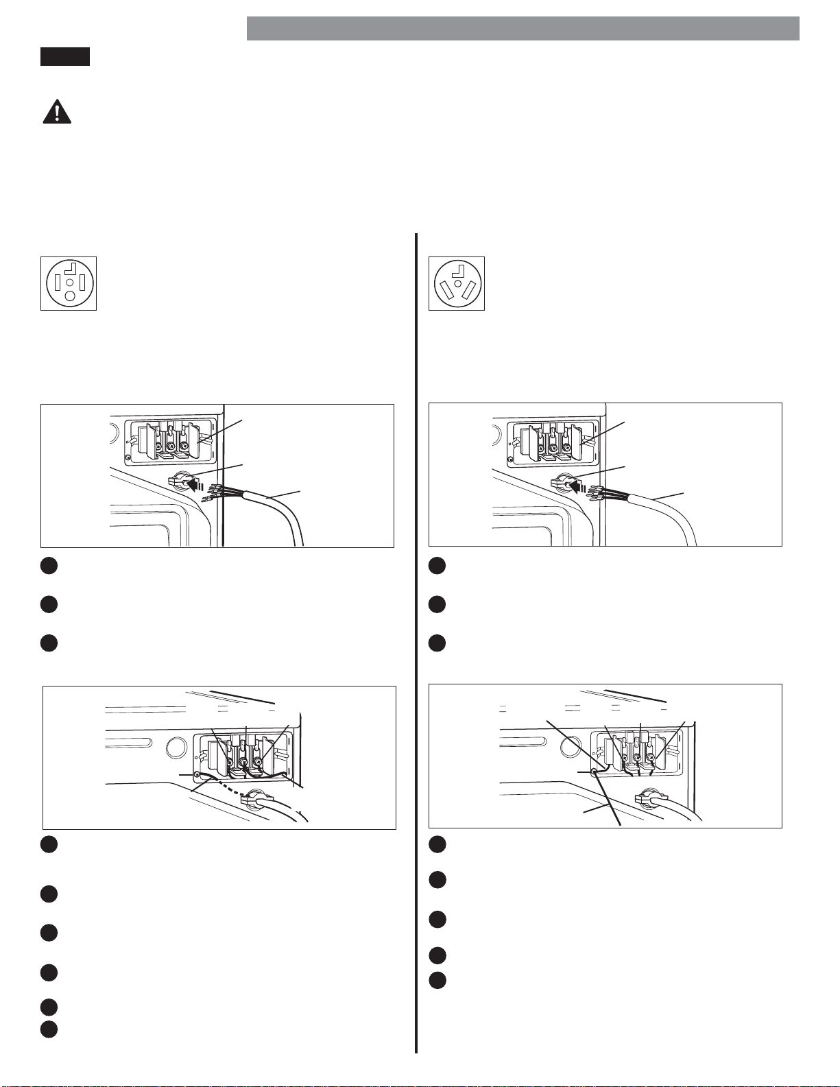
ELECTRIC DRYERS (continued)
CONNECTING ELECTRIC DRYERS
WARNING:
Connect the power cord to the terminal block. Connect
each power cord wire to the terminal block screw that
has the same colored wire. For example, connect the
black power cord wire to the terminal block screw
with the black wire. Failure to follow these instructions
may result in a short, overload fi re or death.
INSTALLATION INSTRUCTIONS
Grounding through the neutral wire is prohibited for: (1)
w branch-circuit installations, (2) mobile homes, (3)
ne
recreational vehicles, and (4) areas where local codes
prohibit grounding through the neutral wire.
Four-Wire Power Cord
• A 4-wire connection is required for all
mobile and manufactured home installations,
as well as all new construction after
January 1, 1996.
• A UL-listed strain relief is required.
• Use a 30-amp, 240-volt, 4-wire, UL-listed power cord
with #10 AWG-minimum copper conductor and closed
loop or forked terminals with upturned ends.
Terminal
Block
UL-Listed
Strain Relief
UL-Listed
4 Wire
Power
Cord
Remove the terminal block access cover on the upper
1
back of the dryer.
Install a UL-listed strain relief into the power cord
2
through-hole.
Thread a 30-amp, 240-volt, 4-wire, UL-listed power
3
cord with #10 AWG-minimum copper conductor
through the strain relief.
Hot
(Black)
Neutral
(White)
Hot
(Red)
Three-Wire Power Cord
• A 3-wire connection is NOT permitted on
new construction after January 1, 1996.
• A UL-listed strain relief is required.
• Use a 30-amp, 240-volt, 3-wire, UL-listed power cord
with #10 AWG-minimum copper conductor and closed
loop or forked terminals with upturned ends.
Terminal
Block
UL-Listed
Strain Relief
UL-Listed
3 Wire
Power
Cord
Remove the terminal block access cover on the upper
1
back of the dr
Install a UL-listed strain relief into the power cord
2
through-hole.
Thread a 30-amp, 240-volt, 3-wire, UL-listed power
3
cord with #10 AWG-minimum copper conductor
through the strain relief.
yer.
Neutral
Grounding
Wire
Hot
(Black)
Neutral
(White)
Hot
(Red)
Green Ground Screw
Green Wire of
Power Cord
Transfer the neutral grounding wire from behind the
44
een ground screw to the center screw of the terminal
gr
block.
5
Attach the two hot leads (black and red) of the power
cord to the outer terminal block screws.
6
Attach the power cord white neutral wire to the center screw of the terminal block.
7
Attach the power cord ground wire to the green
ground screw.
8
TIGHTEN ALL SCREWS SECURELY.
9
Reinstall the terminal block access cover.
Neutral
Grounding
Wire
Green Ground Screw
Ground WireExternal
Attach the two hot leads (black and red) of the
power cord to the outer terminal block screws.
5
Attach the power cord neutral (white) wire to the center
terminal block screw.
6
Connect the external ground (if required by local
codes) to the green ground screw.
7
TIGHTEN ALL SCREWS SECURELY.
8
Reinstall the terminal block access cover.
13
Page 14
INSTALLATION INSTRUCTIONS
VENTING THE DRYER
IMPORTANT!
The most common cause of dryer problems is poor
exhaust venting. Before installing your new dryer,
check the items listed below to make sure you get the
best possible performance. This can save you time and
money by reducing cycle times and increasing energy
effi ciency.
• DIRTY OR DAMAGED EXHAUST DUCTS. Lint builds
up in exhaust ducts over time. This decreases the
airfl ow and makes the dryer work harder. Visually
inspect your ducts from both ends and have them
cleaned if they have not been cleaned recently.
• WRONG VENT MATERIAL. Check your vent to make
sure it is rigid or semi-rigid metal ducting. If your
venting is plastic or fl exible foil, have it replaced
before using the dryer.
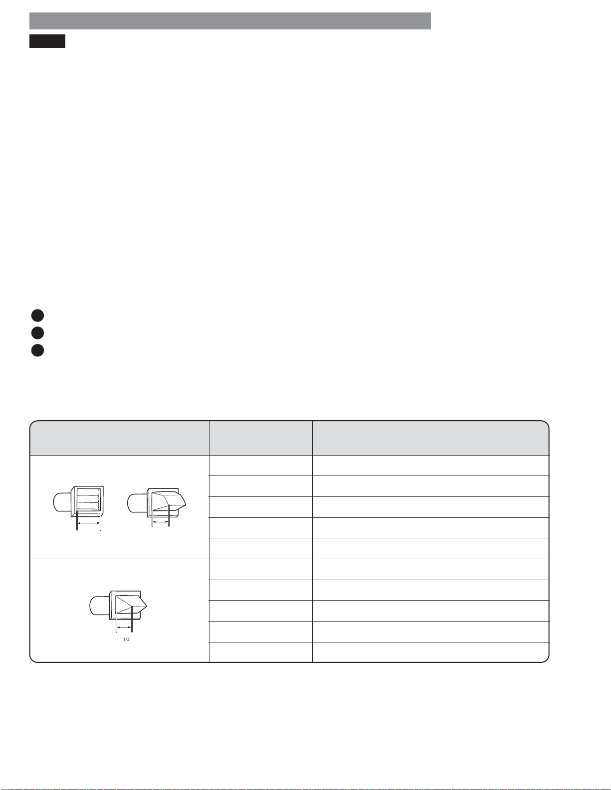
Using the DUCT LENGTH CHART (below)
1
Find your vent hood type in the chart below.
2
Select the row that matches the number of elbows in your dryer duct run.
3
Look to the right of the elbow number for the maximum duct length for your installation. Longer duct length will result
in reduced drying performance, longer dry times and increased energy consumption. Extremely long ducts can even
shorten the life of the dryer.
CHECK YOUR EXHAUST SYSTEM FOR PROBLEMS
• RESTRICTED OR DAMAGED VENT HOOD. Check
your vent hood outside. It must be clean and free of lint
buildup. Check the damper and make sure it opens fully
and easily.
• EXCESSIVELY LONG VENT. Measure the length of your
exhaust system and count the elbows. Use the chart
below to see if your duct is too long. If it is too long,
have the duct routed to another location that is within
the venting guidelines.
• DO NOT USE PLASTIC OR FOIL VENTING. The
transition duct from your dryer to the wall must be rigid
or semi-rigid metal ducting. If your old transition duct is
plastic or foil, REPLACE IT with semi-rigid metal ducting.
DO NOT exceed the maximum length for the vent hood type and number of elbows used.
Maximum length of 4" (10.2 cm )
diameter rigid metal duct
65 feet (19.8 m)
55 feet (16.8 m)
47 feet (13.7 m)
36 feet (11.0 m )
28 feet (8.5 m)
55 feet (16.8 m)
47 feet (13.7 m)
41 feet (12.5 m)
30 feet (9.1 m)
22 feet (6.7 m)
Vent Hood Type
Recommended
4"
(10.2 cm )
Only for Short-Run Installations
1/2
2
(6.35 cm )
4"
(10.2 cm )
"
Number of 90°
Elbows
0
1
2
3
4
0
1
2
3
4
NOTE: Deduct 6 ft. (1.8 m) for each additional elbow. Using more than four 90° elbows is not recommended.
14
Page 15
VENTING THE DRYER (continued)
Routing and Connecting Ductwork
Follow the guidelines below to maximize dryer
performance and reduce lint buildup and condensation
in the ductw
NOTE: T
are NOT included and must be purchased separately.
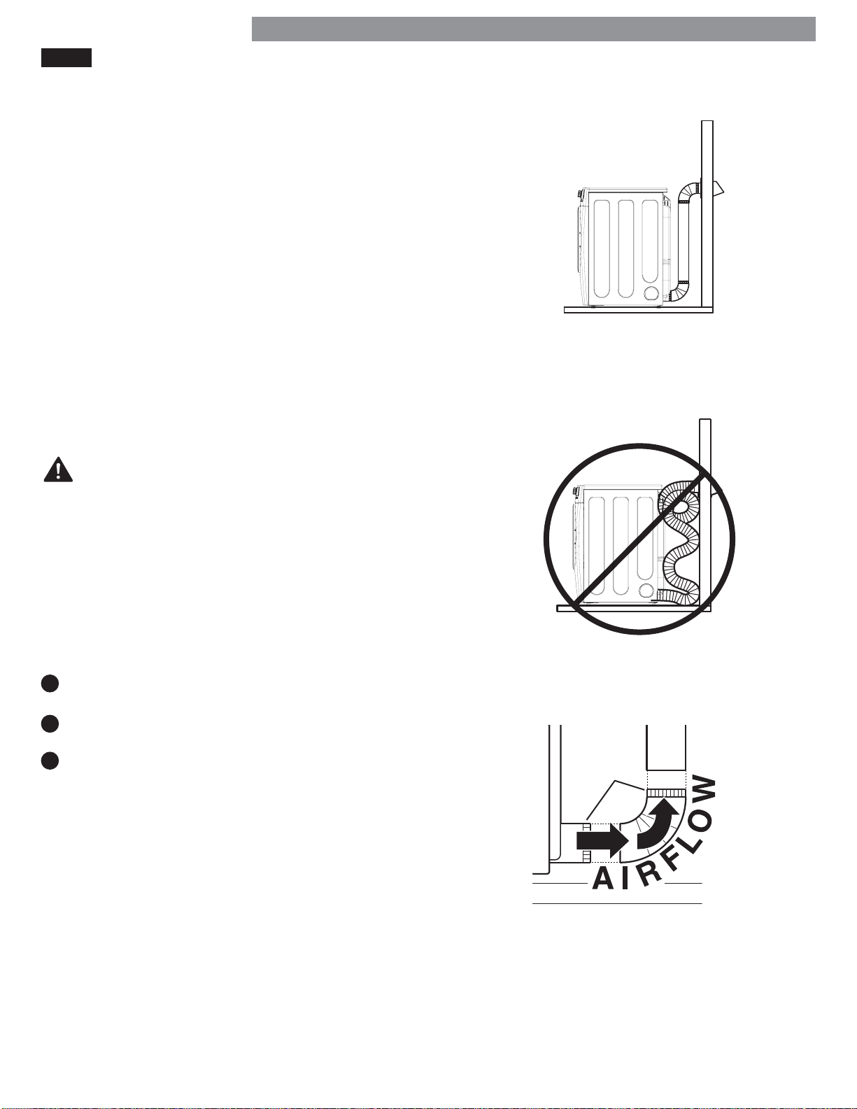
• Use 4 inch (102mm) diameter rigid or semi-rigid
metal duct.
• The exhaust duct run should be as short as possible.
• Use as few elbow joints as possible.
• The male end of each section of exhaust duct must
point away from the dryer. See fi gure on lower right of
page.
• Use duct tape on all joints. Never use screws.
• Insulate ducts that runs through unheated areas in
order to reduce condensation and lint buildup on
duct surfaces.
• The total length of semi-rigid metal transition duct
should not exceed 8 ft. (2.4 m).
ork.
ransition duct (from dryer to wall) and fi ttings
INSTALLATION INSTRUCTIONS
Correct Venting
Incorrect Venting
WARNING:
Failure to follow these
guidelines will result in poor performance, product
failure, and/or result in fi re or death.
IMPORTANT: Failure to exhaust the dryer, per the
guidelines included within these instructions, may
result in unsatisfactory dryer performance. All venting
and ductwork beyond the exterior of the dryer is the
responsibility of the consumer. Product failure, as a
result of improper venting, is not covered by the dryer
warranty.
Connecting the Dryer Vent
1
Verify all ducts and elbows are clean and free
from any blockages.
2
Measure duct length. DO NOT exceed the
maximum length listed in the Duct Length Chart.
3
Connect dryer exhaust to existing duct.
• Only use duct tape or clamps.
• DO NOT use screws to secure ductwork.
• Use rigid or semi-rigid metal ducts.
• DO NOT use plastic or thin metal foil tubing
for ductwork.
• The male end of each elbow must always point in
the direction of the airfl ow.
Male
Ends
15
Page 16
INSTALLATION INSTRUCTIONS
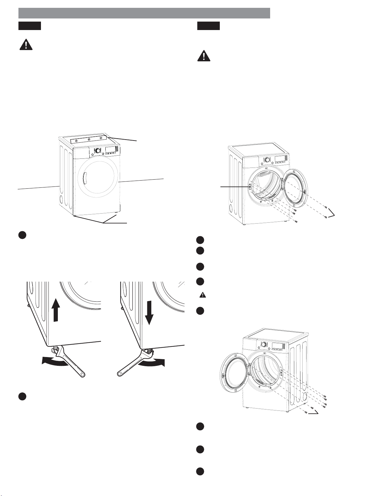
LEVELING THE DRYER REVERSING THE DOOR SWING
INSTALLATION INSTRUCTIONS
WARNING:
• Wear gloves during installation.
• Failure to follow these instructions can result in injury.
To ensure that the dryer provides optimal drying
performance, it must be level. To minimize vibration,
noise, and unwanted movement, the fl oor must be a
level, solid surface.
NOTE: Adjust the leveling feet only as far as necessary
to level the dryer. Extending the leveling feet more than
necessary can cause the dryer to vibrate.
Level
Level
The swing of the dryer door can be reversed to fi t your
installation location.
WARNING:
THE DRYER DOOR IS VERY LARGE AND HEAVY.
Failure to follow the instructions below can result in
damage to the dryer, property damage or personal injury.
• To avoid damage to the dryer or the door, support the
door with a stool or box that fi ts under the door, or
have an assistant support the weight of the door.
• Always reverse the door BEFORE stacking the dryer on
top of the washer
• Avoid dropping the door to avoid damage to the door
or the fl oor.
Door
Latch
Leveling Feet
Leveling Feet
1
Position the dryer in the fi nal location. Place a level
across the top of the dryer.
All four leveling feet must rest solidly on the fl oor.
Gently push on the top corners of the dryer to make
sure that the dryer does not rock from corner to corner.
Hinge
Screws
Latch Screws
1
Open the dryer door.
2
Using a Phillips screwdriver, remove the two latch
screws and the latch.
Remove the two hole caps, one each above and
3
below the latch by rotating them slightly clockwise.
4
While supporting the weight of the door, remove the
four hinge screws.
CAUTION: Be sure to support the weight of the door
e removing the hinge screws.
befor
5
Carefully turn the door upside down and reinstall it on
the opposite side using the screws removed in step 4.
Use a wrench to turn the leveling feet. Turn the
2
leveling foot clockwise to raise the dryer; turn the
foot counterclockwise to lower the dryer. Using a
level, adjust the feet until the dryer is level from side
to side and front to back. Make sure all four feet
are in fi rm contact with the fl oor.
NOTE: If you are installing the dryer on the optional
pedestal, the dryer leveling feet should be fully retracted.
Use the leveling feet on the pedestal to level the dryer.
16
Latch Screws
Hinge Screws
6
Install the door latch in the opening on the side from
which the door was removed using the screws from
step 2.
7
Install the hole caps removed in step 3 in the holes
above and below the latch where the door was
originally mounted.
8
Test the door for proper operation and make sure it
latches properly.
Page 17
INSTALLATION INSTRUCTIONS
FINAL INSTALLATION CHECK
INSTALLATION INSTRUCTIONS
Once you have completed the installation of the dryer
and it is in its fi nal location, confi rm proper operation
with the following steps and tests.
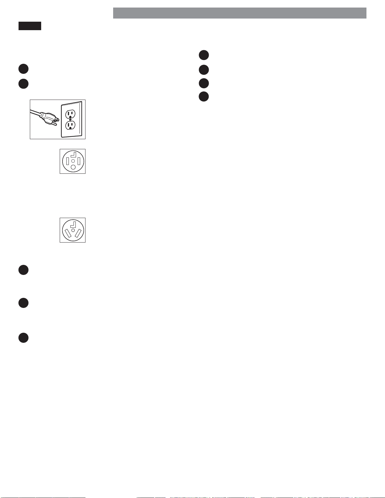
1
Is gas turned on? (Gas models only)
Is dryer plugged in? Dryer should always be
2
plugged into the proper outlet.
Gas dryer should use a
120-VAC, 60-Hz. grounded
3-prong outlet.
Electric dryer should use a
4-wire connection which is
required for all mobile
and manufactured home
installations, as well as all new
construction after
January 1, 1996.
-- OR --
A 3-wire connection.
NOTE: A 3-wire connection
is NOT permitted on new
construction after
January 1, 1996.
Testing Dryer Heating
1
Close the dryer door.
2
Press the POWER button to turn the dryer on.
3
Turn the cycle selector knob to Normal drying cycle.
4
Press the START/PAUSE button to start the dryer.
After three minutes, open the dryer door and check
that the air inside is warm.
NOTE: If the air inside the dryer is not warm after
three minutes, there may be air in the gas supply line to
the dryer, and the gas igniter may turn off before the
main burner ignites. When this happens, the igniter will
continue to attempt main burner ignition until all air is
purged from the line. Once ignition occurs, the air inside
the dryer will become warm.
Checking Venting
Vent ductwork should be checked for lint buildup
and cleaned at least once per year. If any noticeable
reduction in drying performance occurs, check the duct
for obstructions and blockages.
Is the dryer transition duct from dryer to wall
3
connected? Make sure the transition duct behind the
dryer is properly connected and is not crushed or
damaged.
4
Is dryer level? Once the dryer is in its fi nal location,
recheck the dryer to be sure it is level. Make sure it is
level front to back and side to side, and that all four
leveling feet rest fi rmly on the fl oor.
5
Is the dryer heating normally? Perform the following
dryer heating test.
17
Page 18
HOW TO USE
To reduce the risk of fi re, electric shock, or injury to persons, read this entire
WARNING:
manual, including the Important Safety Instructions, before operating this dryer.
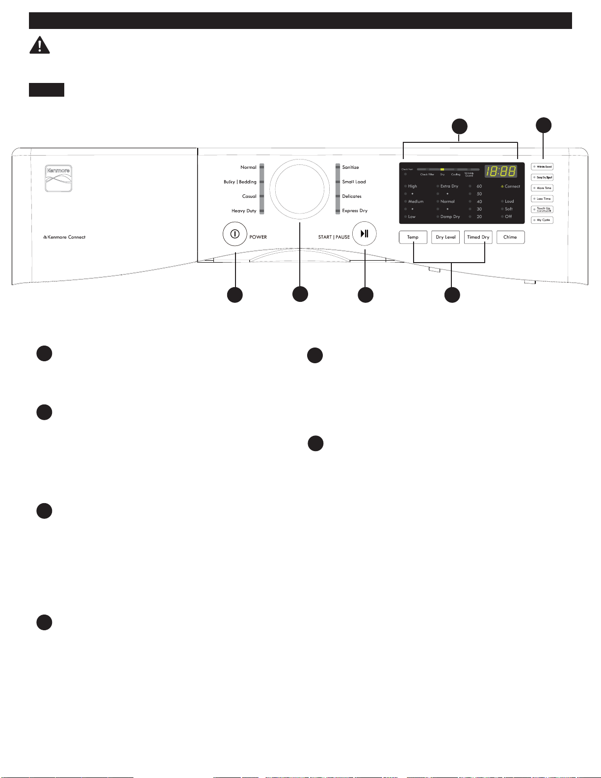
CONTROL PANEL FEATURES
A
POWER (ON/OFF) BUTTON
Press to turn the dryer ON or OFF. Pressing the
POWER button during a cycle will cancel that cycle
and any settings will be lost.
CYCLE SELECTOR KNOB
B
The cycle selector knob is used to select the desired
dry cycle by rotating the knob in either direction until
the desired cycle LED is illuminated. Once the desired
cycle has been selected, the standard presets for that
cycle will show in the display. These settings can be
adjusted using the cycle modifi er or option buttons
any time before starting the cycle.
C
START/PAUSE BUTTON
Press this button to start the selected cycle. The
dryer will display the estimated time (AUTO DRY) or
set time (TIMED DRY) remaining and start tumbling.
To pause the cycle at any time, open the dryer door
or press START/PAUSE. To resume the cycle where it
was stopped, press START/PAUSE again.
NOTE: If the dryer has been stopped for more than
four minutes, the dryer will turn off automatically.
F
B
E
CYCLE MODIFIER BUTTONS
Use these buttons to adjust the settings for the
selected cycle. The settings light up above the
buttons to show the current selection. The default
temperature setting cannot be changed in AUTO
DRY cycles. AUTO DRY cycles are modifi ed using
the DRY LEVEL button.
F
TIME AND STATUS DISPLAY
The display shows the estimated time remaining for
auto cycles and actual time for timed cycles. The
status of the cycle is also displayed. The CHECK
VENT indicator will illuminate if there is a serious
restriction in the exhaust system.
CA
E
D
D
OPTION BUTTONS
These buttons allow you to select cycle options.
Some of the option buttons have secondary
functions. The controls can be locked or unlocked by
pressing and holding the CONTROL LOCK button
for fi ve seconds.
NOTE: T
o protect your fabrics, not all settings are allowed in all cycles.
18
Page 19
OPERATING THE DRYER
HOW TO USE
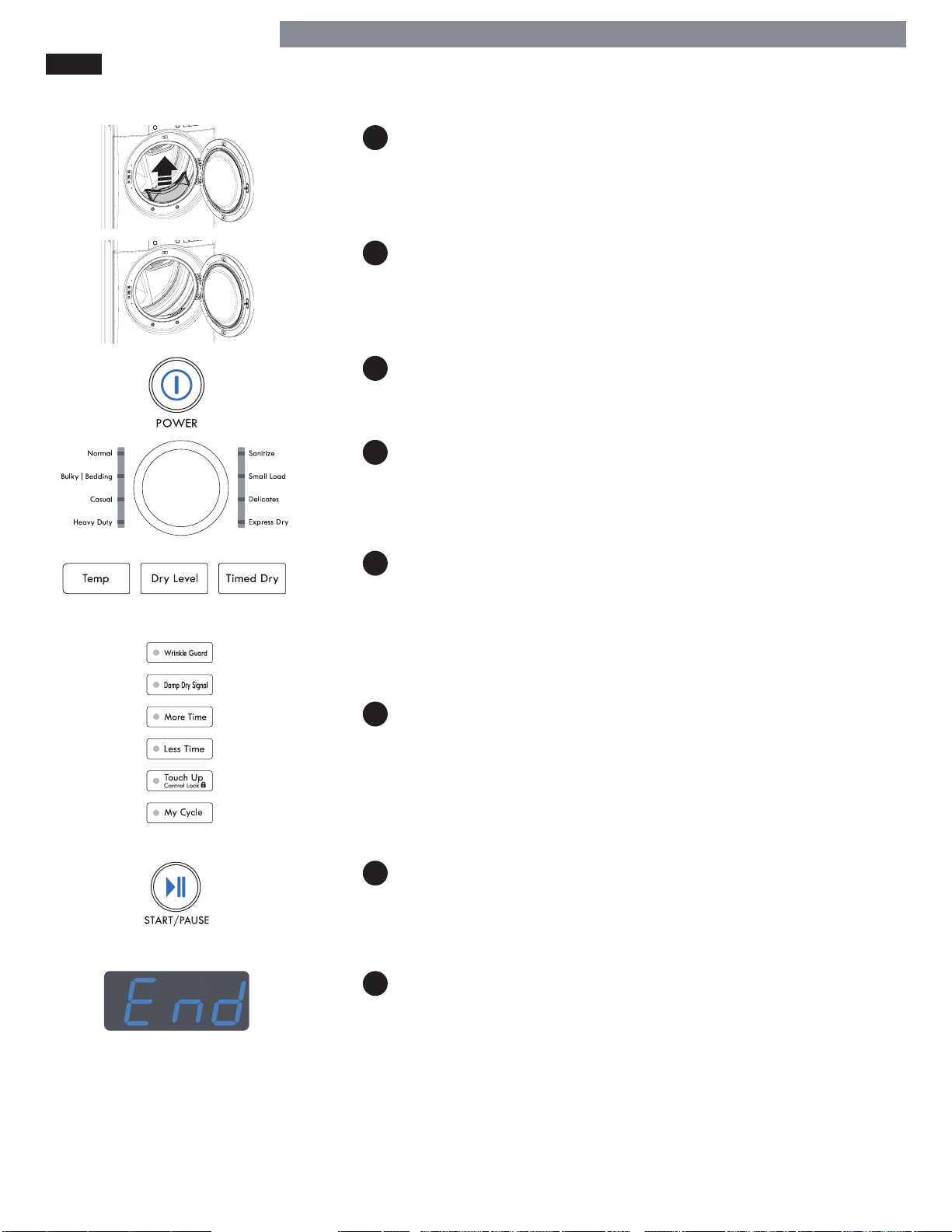
CLEAN THE LINT FILTER
1
If the lint fi lter has not already been cleaned, lift out the fi lter and
remove the lint from the last load. This will help ensure the fastest
and most effi cient drying performance.
LOAD THE DRYER
2
Load the dryer with the wet laundry from the washer. If the load is
extra large, you may need to divide it into smaller loads for proper
performance and fabric care.
TURN ON THE DRYER
3
Press the POWER button to turn ON the dryer. The cycle LEDs will
illuminate and a chime will sound.
SELECT A CYCLE
4
Turn the cycle selector knob in either direction until the LED for the
desired cycle is illuminated. The preset temperature, dry level, and
option settings for that cycle will display.
SELECT CYCLE MODIFIERS
5
Default settings for the selected cycle can now be changed, if
desired.
NOTE: Not all options or modifi ers are available with all cycles.
Temperature can only be adjusted on Timed Dry cycles; Dry Level is
only available on Auto Dry cycles. A diff erent chime will sound and
the LED will not illuminate if the selection is not allowed.
SELECT CYCLE OPTIONS
6
Cycle options can be added using the option buttons.
NOTE: Not all options or modifi ers are available with all cycles.
A diff erent chime will sound and the LED will not come on if the
selection is not allowed.
BEGIN CYCLE
7
Press the START/PAUSE button to begin the cycle. The cycle can be
paused at any time by opening the door or by pressing the START/
PAUSE button. If the cycle is not restarted within four minutes of being
paused, the dryer will shut off and the settings will be lost.
END OF CYCLE
8
When the cycle is fi nished, a chime will sound. Immediately remove
your clothing from the dryer to reduce wrinkling. If WRINKLE
GUARD is selected, the dryer will tumble briefl y every few minutes
to help prevent wrinkles from setting in the clothes.
19
Page 20
HOW TO USE
CYCLE GUIDE
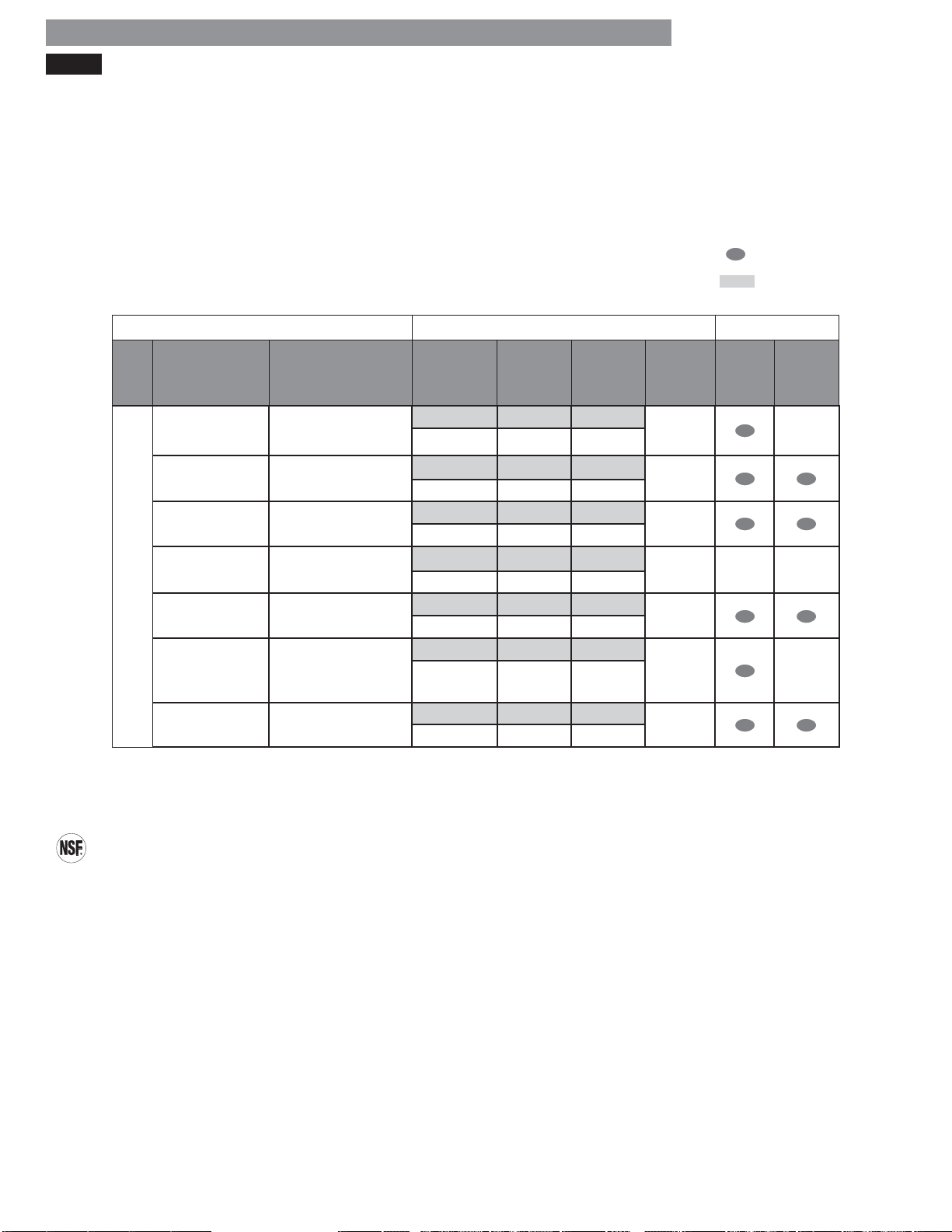
The cycle guide below shows the available options and recommended fabric types for AUTO DRY cycles.
*NOTE: The default time and actual time will vary depending on the size of the load and moisture content.
Auto Dry Cycles
Auto Dry cycles utilize a sensor that detects moisture levels in the clothes and adjusts the drying time as needed to ensure superior
results. The dryer automatically sets the dry level and temperature at the recommended setting for each cycle. The estimated time
remaining will be shown in the display.
= available option
= default setting
Modifi ers Options
Mor
Type Cycle Fabric Type Temperature Dry Level
Sanitize
Heavy Duty
Casual
Bulky/Bedding
AUTO DRY
NOTE: To protect your garments, not every dry level, or option is available with every cycle. Temperature settings cannot be
changed. A diff erent chime will sound and the LED will not illuminate or the selection will not change if the selection is not allowed.
Normal Work clothes, etc.
Small Load
Delicates
Comforter, bedding,
children’s clothing, etc.
Jeans, heavyweight
items
Permanent press,
synthetic items
Comforter, pillows,
shirts
Only normal &
cotton/towel fabric
type (Max 3 lb)
Lingerie, sheets,
blouses
High Extra dry 70
High Normal 54
Adjustable
Mid low Normal 32
Adjustable
Medium Normal 55
Adjustable
Medium Normal 41
Adjustable
High Normal 30
Adjustable
Mid low Normal 28
Adjustable
*Time in
Min.
e
Time/Less
Time
Wrinkle
Guard
Damp
Dry
Signal
CERTIFIED BY NSF
NSF International (formerly the National Sanitation Foundation), certifi es that the SANITIZE cycle reduces 99.9% of bacteria on
laundry, and none of the bacteria will carry over onto the next laundry load.
• The default settings for the SANITIZE cycle are HIGH temperature and EXTRA DRY. These default settings cannot be
changed.
• Do NOT use this cycle with delicate items or fabrics.
20
Page 21
HOW TO USE
CYCLE GUIDE
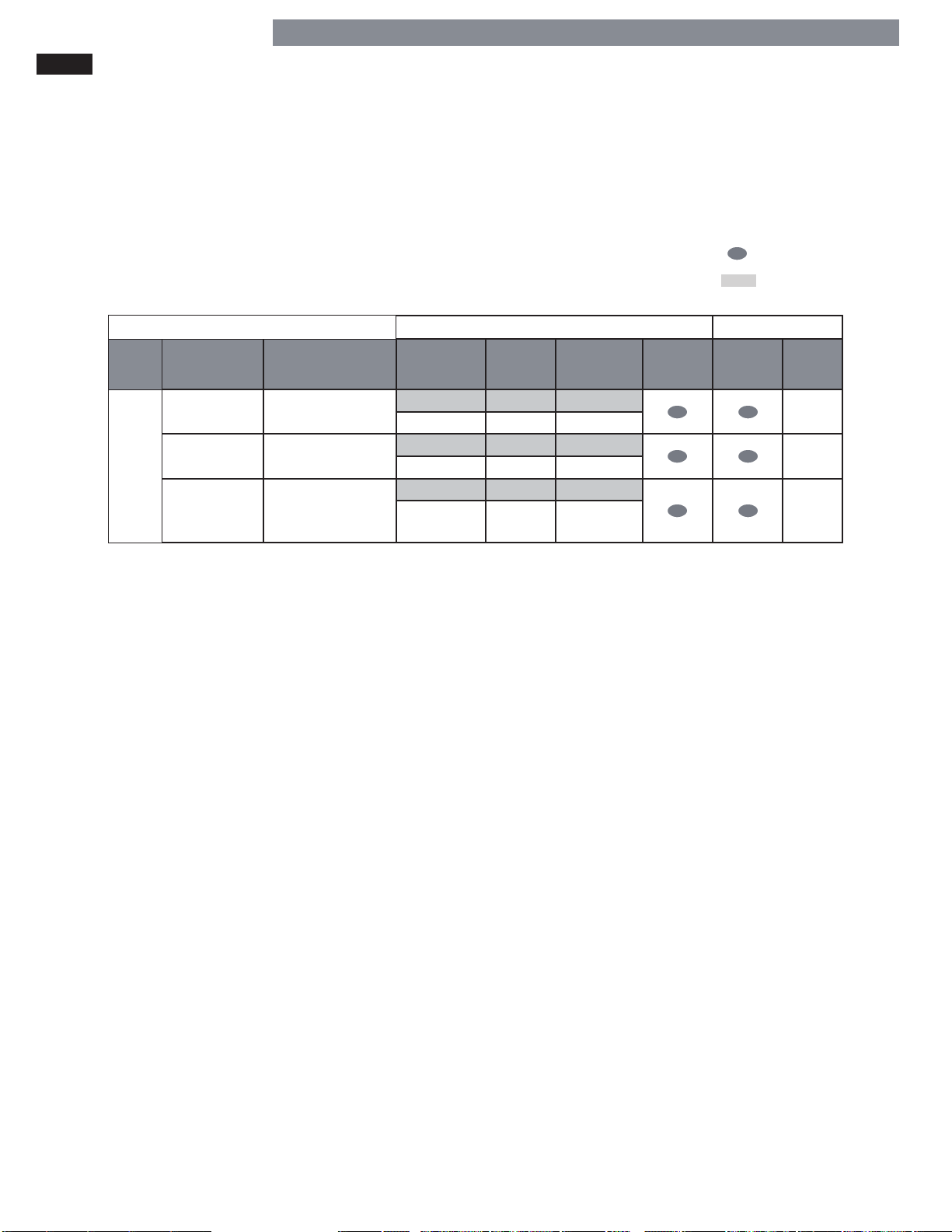
The cycle guide below shows the available options and recommended fabric types for TIMED DRY cycles.
Timed Dry Cycles
Use Timed Dry cycles to select a specifi c amount of drying time and the drying temperature. When a TIMED DRY
cycle is selected, the display shows the actual time remaining in your cycle.
You can change the actual time for the cycle by pressing MORE TIME or LESS TIME. Press and hold the MORE TIME or
LESS TIME buttons to rapidly change the time.
= available option
= default setting
Modifi ers Options
Type Cycle Fabric Type Temperature Dry Level
High Auto 25
Adjustable Max. 100
Mid high Auto 20
Adjustable Max. 100
High Auto 40
Adjustable Max. 100
TIMED DRY
Express Dry
Touch Up
Timed Dry*
For small loads with
short drying times
For removing light
wrinkles
For general drying.
Time, temperature,
and options can be
set manually
*Time in
Min.
More
Time/Less
Time
Wrinkle
Guard
Damp
Dry
Signal
NOTE: To protect your garments, not every temperature or option is available with every cycle. Temperature settings
cannot be changed. A diff erent chime will sound and the LED will not illuminate if the selection is not allowed.
*Timed Dry is accessed by pressing the Timed Dry button in the Cycle Modifi ers fi eld of the of the Control Panel.
21
Page 22
HOW TO USE
To reduce the risk of fi re, electric shock, or injury to persons, read this entire manual,
WARNING:
including the Important Safety Instructions, before operating this dryer.
SORTING LOADS LOADING THE DRYER
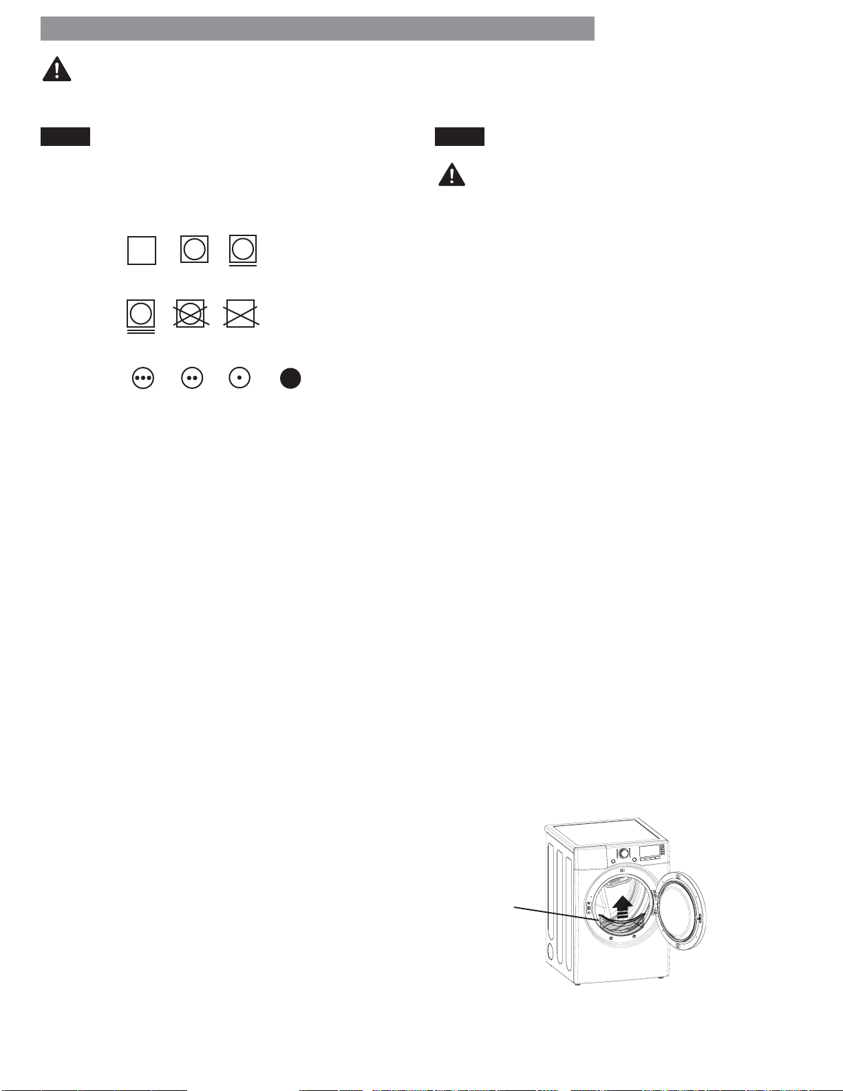
Fabric Care Labels
Most articles of clothing feature fabric care labels that
include instructions for proper care.
Tumble
dry
Heat
setting
Group Similar Items
For best results, sort clothes into loads that can be dried
with the same drying cycle.
Diff erent fabrics have diff erent care requirements, and
some fabrics will dry more quickly than others. For best
fabric care results, always dry fabrics with similar care
requirements together.
Dry
Gentle/
delicate
High
Normal
Do not
tumble dry
Medium Low
Permanent Press/
wrinkle resistant
Do not dry
(used with do
not wash)
No heat/air
WARNING:
To reduce the risk of
fi re, electric shock, or injury to persons when using
this appliance, follow basic precautions, including the
following:
• Check all pockets to make sure that they are empty.
Items such as clips, pens, coins, and keys can damage
both your dryer and your clothes. Flammable objects
such as lighters or matches could ignite, causing a
fi re. Failure to follow this warning can result in fi re,
explosion, or death.
• Never dry clothes that have been exposed to oil,
gasoline, or other fl ammable substances. Washing
clothes will not completely remove oil residues. Failure
to obey this warning can result in fi re, explosion,
or death.
Loading Tips
• Combine large and small items in the same load.
• Damp clothes will expand as they dry. Do not overload
the dryer; clothes require room to tumble and
dry properly.
• Close zippers, hooks, and drawstrings to prevent these
items from snagging or tangling on other clothes.
CHECK THE LINT FILTER BEFORE EVERY LOAD
Every time the dryer is turned on, the CHECK FILTER
light will blink as a reminder to make sure the fi lter is
clean. Always make sure the lint fi lter is clean before
starting a new load; a clogged lint fi lter will increase
drying times. To clean, pull the lint fi lter straight up and
roll any lint off the fi lter with your fi ngers. Do not rinse
or wash the fi lter to remove lint. Push the lint fi lter fi rmly
back into place.
Always ensure the lint fi lter is properly installed before
running the dryer. Running the dryer with a loose or
missing lint fi lter may damage the dryer and articles in
the dryer.
Lint Filter
22
Page 23
HOW TO USE
TIME AND STATUS DISPLAY
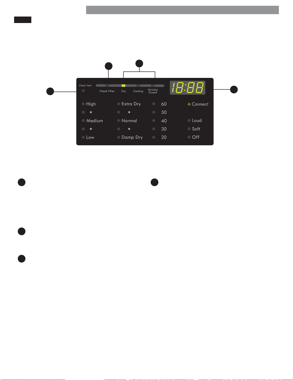
The Time and Status Display shows the cycle time, cycle progress, and vent status. When the dryer is turned on, the
display will illuminate.
B
D
AD
TIME DISPLAY
When a cycle is selected, the display will indicate
the default time for that cycle including selected
options or adjustments. In AUTO DRY cycles, the
time remaining will be estimated and may change
during the cycle, depending on the condition of the
load. In TIMED DRY, the time displayed will be the
actual time remaining.
B
CHECK FILTER LIGHT
The CHECK FILTER light will blink before each load,
as a reminder to check the lint fi lter. Always clean
the lint fi lter before every cycle.
C
A
CHECK VENT INDICATOR
(DUCT BLOCKAGE SENSING SYSTEM)
The CHECK VENT duct blockage sensing system
detects and alerts you to blockages in the ductwork
that reduce exhaust fl ow from the dryer. This light
does not indicate any problems with your dryer. If
this light blinks, it indicates that your home’s exhaust
system has a serious restriction, which is not covered
by your dryer’s warranty. Call 1-800-4-MY-HOME
for information regarding duct cleaning services
off ered through Sears.
®
C
CYCLE STATUS INDICATORS
This portion of the display shows which stage of the
drying cycle is currently under way (DRY, COOLING,
or WRINKLE GUARD).
23
Page 24
HOW TO USE
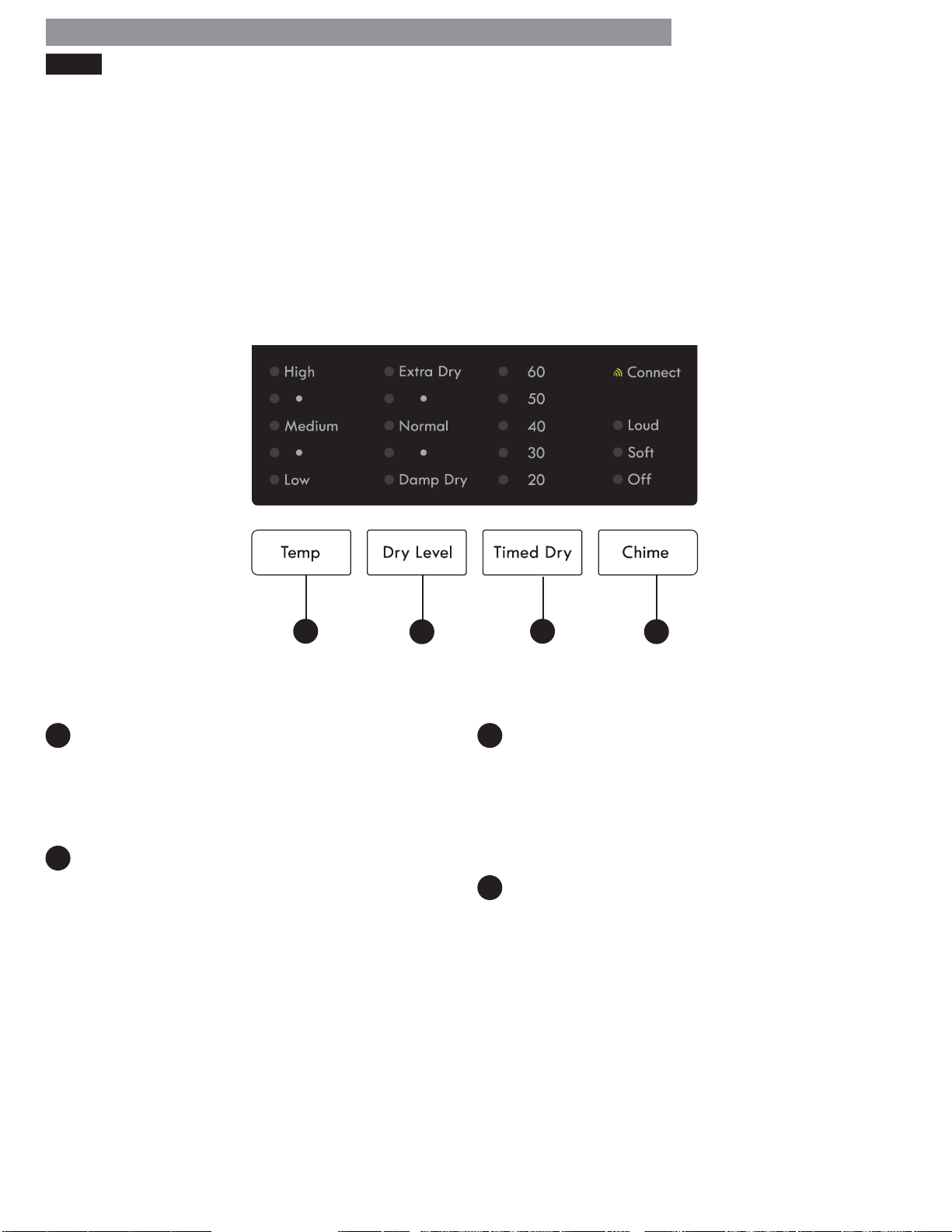
CYCLE MODIFIER BUTTONS
Each cycle has default settings that are selected
automatically
using the cycle modifi er buttons.
AUTO DRY cycles are designed to properly care for
specifi c fabrics and loads. As a result, not all settings are
available for each cycle selection.
TIMED DRY cycles have default settings, but you may
also customize the temperature setting and add options.
Settings are not limited in most timed dry cycles. Use
care when setting options and modifi ers for these cycles
to prevent damage to your clothing.
. You may also customize these settings
NOTE: To protect your garments, not every dry level,
temperature, or option is available with every cycle.
A
AC
TEMP
Adjusts the temperature setting from LOW to
HIGH. This allows precise care of your fabrics and
garments. Press the TEMP button repeatedly to scroll
through available settings. The temperature setting is
not adjustable in AUTO DRY cycles.
B
DRY LEVEL
Sets the level of dryness for the selected AUTO DRY
cycle. Press the DRY LEVEL button repeatedly to
scroll through available settings. Use this button to
adjust the dryness of the articles in the load to
your preference.
• This option is not available with TIMED DRY cycles.
• The dryer will automatically adjust the cycle time.
Selecting EXTRA DRY will increase the cycle time
and dry level, while DAMP DRY will decrease the
cycle time and dry level.
• Use the DAMP DRY setting for items that you wish
to iron or hang for fi nal drying.
B
D
C
TIMED DRY
Allows you to manually select the drying time in
10-minute increments. Use this cycle for small loads
or to remove wrinkles. Use the MORE TIME/LESS
TIME buttons to increase or decrease the selected
drying time in 1-minute increments. Press and hold
the MORE TIME or LESS TIME buttons to rapidly
change the time.
CHIME
Adjusts the volume of the chime or turns off the
chime. Press the button repeatedly until the desired
volume setting is illuminated.
D
24
Page 25
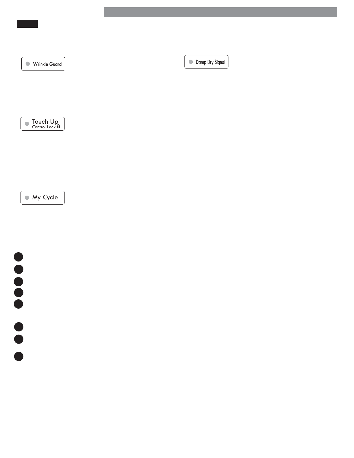
CYCLE OPTIONS AND SPECIAL FEATURES
Your dryer features several additional cycle options and special features to meet your individual needs.
HOW TO USE
WRINKLE GUARD
Selecting this option will tumble the
clothes after the cycle ends for a few
seconds every few minutes without
heat. This option is active for 150
minutes after the end of the cycle, or until the door is
opened. This helps prevent wrinkles if the clothes are not
removed immediately after the cycle has fi nished.
CONTROL LOCK
Use this option to disable the
controls. The Control Lock can be
activated any time the dryer is ON.
When the controls are locked “CL”
will display alternately with the estimated time
remaining. Once set, the Control Lock must be turned off
before the controls can be used.
Press and hold the TOUCH UP button for fi ve seconds to
lock or unlock the controls.
MY CYCLE
My Cycle allows you to store a
customized dry cycle for future use. It
allows you to save favorite temperature,
dry level, and other options for a cycle,
and then recall them at the touch of a button.
NOTE: O
and hold the MY CYCLE button to overwrite any previously saved cycle.
nly one My Cycle can be saved at a time. Press
DAMP DRY SIGNAL
If you press the Damp Dry Signal,
the dryer will emit a chime when the
clothes are just short of completely
dry, in case you want to remove them for ironing or
hang drying.
To save a MY CYCLE:
1
Press the POWER button to turn on the dryer.
Turn the cycle selector knob to select the desired cycle.
2
Press the CYCLE MODIFIER button to change the desired setting.
3
Press the CYCLE OPTION button to add the desired options.
4
Press and hold the MY CYCLE button.
5
To recall a MY CYCLE:
1
Press the POWER button to turn on the dryer.
Press the MY CYCLE button. The stored settings will
2
be displayed.
Press the START/PAUSE button to start the cycle.
3
NOTE: My Cycle can be adjusted the same as any
other cycle. However, once any other button is pressed,
the LED will turn off , indicating that the settings are no
longer those of your saved cycle.
25
Page 26
USER MAINTENANCE INSTRUCTIONS
To reduce the risk of fi re, electric shock, or injury to persons, read this entire manual,
WARNING:
including the Important Safety Instructions, before operating this dryer.
• Unplug the dryer or turn the power off before cleaning to avoid the risk of electric shock. Failure to follow this
warning can cause serious injury, fi re, electrical shock, or death.
• Never use harsh chemicals, abrasive cleaners, or solvents to clean the dryer. They will damage the fi nish.
REGULAR CLEANING
Cleaning the Exterior
Proper care of your dryer can extend its life. The outside
of the machine can be cleaned with warm water and
a mild, nonabrasive household detergent. Immediately
wipe off any spills with a soft, damp cloth.
IMPORTANT: Do not use cleaning alcohols, solvents, or
similar products.
NEVER use steel wool or abrasive cleansers because
they can damage the surface.
Cleaning the Interior
Wipe around the door opening and seal with a soft,
damp cloth to prevent lint and dust buildup that could
damage the door seal.
Clean the window with a soft cloth dampened with
warm water and a mild, nonabrasive household
detergent, then wipe dry.
NEVER use steel wool or abrasive cleansers; they can
scratch or damage the surface.
Cleaning Around and Under the Dryer
Vacuum lint and dust from around the dryer and
underneath it regularly.
ALWAYS make sure the lint fi lter is clean before every
cycle. The Check Lint Filter Light on the control panel
will blink before every cycle to remind you.
NOTE: NEVER operate the dryer without the lint fi lter.
To remove lint between cycles:
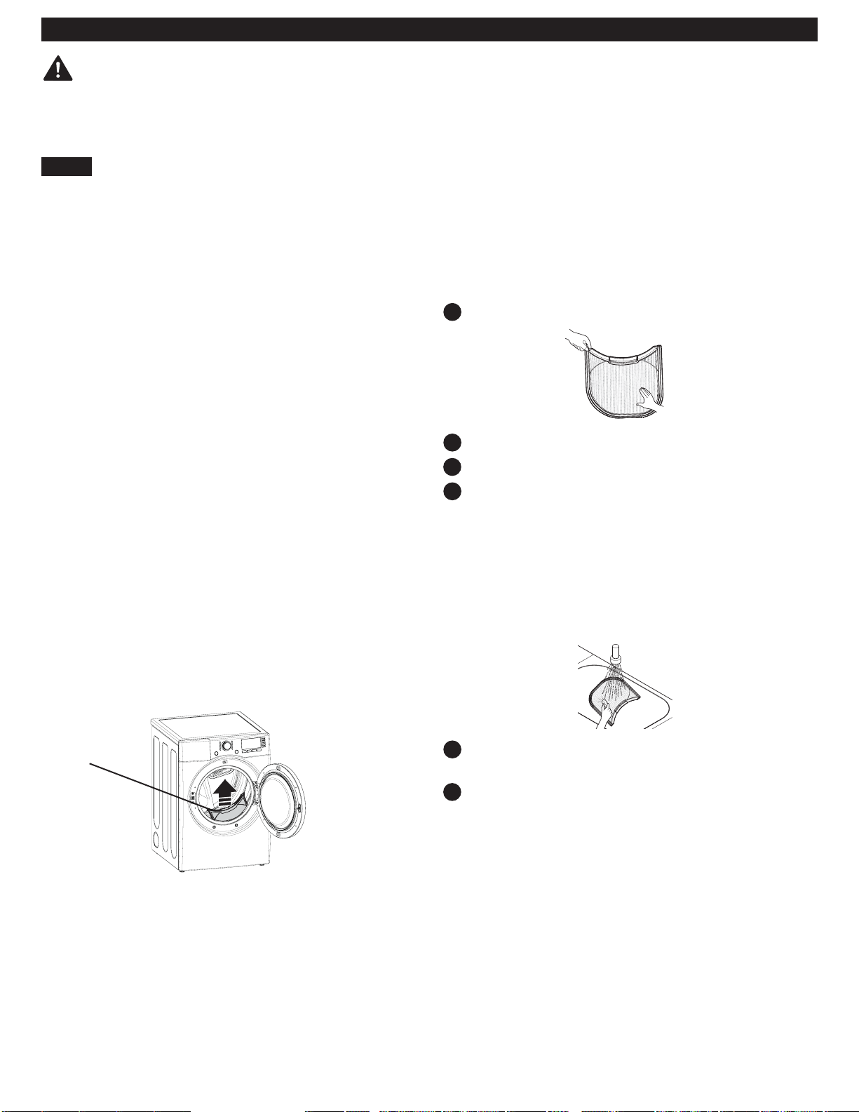
1
Open the dryer door.
2
Pull the lint fi lter straight up.
3
Roll any lint off the fi lter with your fi ngers.
4
Insert the lint fi lter back into the dryer.
Periodic thorough cleaning:
Some fabric softeners can build up on the lint fi lter over
time. This buildup can restrict the airfl ow through the
fi lter reducing dryer effi ciency and lengthening drying
times. After removing lint, if the fi lter looks dark or dirty
when held up to the light, follow these steps to clean:
Cleaning the Lint Filter
Lint
Filter
1
Use hot soapy water and a stiff brush to clean
the fi lter.
Make sure the fi lter is completely dry before
2
reinstalling it and using the dryer.
NOTE: NEVER operate the dryer with a wet lint fi lter.
Maintaining Ductwork
Vent ductwork should be checked for lint build up once
per month and cleaned at least once per year. If any
noticeable reduction in airfl ow or drying performance
occurs, immediately check the ductwork for obstructions
and blockages. Contact a qualifi ed technician or service
provider.
26
Page 27

MAINTAINING THE EXHAUST SYSTEM
USER MAINTENANCE INSTRUCTIONS
The most common cause of dryer problems is poor exhaust venting. P
following conditions:
• DIRTY OR DAMAGED EXHAUST DUCTS
• WRONG VENT MATERIAL
• RESTRICTED OR DAMAGED VENT HOOD
• EXCESSIVELY LONG VENT
• THE USE OF PLASTIC OR FOIL VENTING
Maintaining the Exhaust System
Vent ducts should be checked for lint buildup and
cleaned at least once per year. If any noticeable
reduction in drying performance occurs, check the ducts
for obstructions and blockages.
If the CHECK VENT indicator illuminates, the exhaust
system should be checked immediately for damage
or obstructions. The CHECK VENT indicator signals a
serious reduction in exhaust airfl ow which will greatly
reduce energy effi ciency and increase drying times.
Damaged or restricted exhaust systems are not covered
by the dryer warranty. Damage to the dryer that is
caused by damaged, restricted, or otherwise inadequate
exhaust systems is not covered by the dryer warranty.
CHECK VENT Indicator
The CHECK VENT warning system is designed to
help you avoid the reduced performance caused by
restrictions in the household exhaust system. The CHECK
VENT indicator illuminates to alert you when problems
in the system occur, so you can have them repaired.
While you should always check and maintain your
exhaust system regularly, the CHECK VENT warning
system will detect and alert you if serious problems
develop in your home’s exhaust system. This includes
exhaust systems that are unsatisfactory for any reason
including a blockage in the venting, crushed/kinked
venting, or venting which exceeds the maximum
recommended length requirement as described in the
installation section.
NOTE: The total length includes the length from the
back of the dryer to the outside vent hood, PLUS a
factor for every 90° elbow in the exhaust system. For
example, if the distance from the back of the dryer to
the vent hood is 30 feet, and there are four elbows in
the system, then it exceeds the 28 foot maximum length
allowed for those conditions as specifi ed in the Duct
Length Chart.
The CHECK VENT indicator on the control panel will
alert you that the exhaust system is not moving enough
air from the dryer to the outside. This lack of airfl ow will
lead to long dry times, poor drying and possibly dryer
failure.
As a reminder, external dryer venting is considered
part of your home and is not covered by the product
warranty or protection agreements. There are services
available for cleaning/maintaining the external venting.
Sears provides this service via Sears Carpet, Upholstery,
and Duct Cleaning. Call 1-800-661-6594 to schedule
duct cleaning service from Sears (if it is available in
your area).
oor exhaust venting may result from the
CHECK VENT Operation
The CHECK VENT system uses components already
in the dryer. By monitoring these components over the
course of several cycles, the control is able to determine
how much restriction there is in the exhaust system. If
it detects a high level of restriction, it will turn on the
CHECK VENT light to alert you to the condition. The
dryer will continue to operate after the light comes
on, but you should have the exhaust system cleaned or
repaired immediately to avoid longer dry times and
higher energy consumption.
IMPORTANT: In order for a dryer to properly and
effi ciently dry your clothes, it is extremely important that
the exhaust system is as short and clean as possible. It
MUST be less than the maximum length specifi cations
as outlined in the installation section. It is also very
important that you make sure that when the dryer is
installed, the exhaust system is clean and clear of any
restrictions and is not kinked or crushed.
Failure to meet these guidelines will result in long dry
times, increased energy consumption and possibly even
clothing damage or dryer failure. When exhaust system
restrictions become extreme, the CHECK VENT light will
blink to alert you to the condition so you can have the
exhaust system cleaned or repaired.
1
To prevent false alarms and for increased reliability,
the dryer will monitor the exhaust condition for
several loads. If multiple, consecutive cycles exceed
the restriction limits, the control will blink the CHECK
VENT indicator.
A blinking CHECK VENT indicator means the external
2
venting should be checked for potential restrictions as
soon as possible.
3
The CHECK VENT indicator will remain active
(blinking) until the restriction is resolved AND the
control has verifi ed the improved airfl ow for
several cycles.
4
After the exhaust is cleaned or repaired, it will take
several cycles for the CHECK VENT indicator to reset
and turn off the light.
NOTE: The CHECK VENT indicator is designed to
measure performance over several consecutive cycles
before activating or deactivating, to avoid false alarms.
A very large load, such as a large comforter, could
cause the CHECK VENT system to sense that the exhaust
system is restricted, but this would not cause the light to
blink. However, if several large loads were to run back
to back, the CHECK VENT indicator could be activated.
27
Page 28
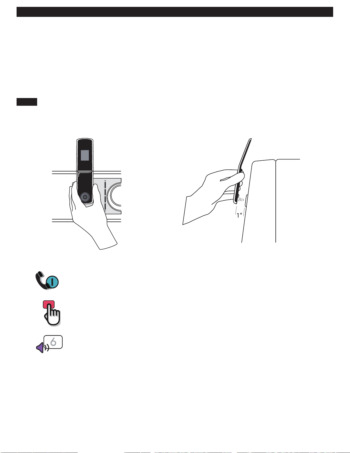
Kenmore Connect™ System
Should you experience any problems with your
dryer, it has the capability of transmitting data via
your telephone to the Kenmore Connect Team. This
gives you the capability of speaking directly to our
specially trained technicians. The technician records
the data transmitted from your machine and uses it
to analyze the issue, providing a fast and eff ective
diagnosis.
Using the Kenmore Connect™ System
Follow the technician’s instructions and perform
the following steps when requested.
If you experience problems with your dryer, call
1-800-4-MY-HOME
System feature when instructed to do so by the
Kenmore Connect Team. The transmission sounds that
you will hear are normal and sound similar to a fax
machine.
Kenmore Connect cannot be activated unless your
dryer is turned on by pressing the POWER button. If
your dryer is unable to turn on, then troubleshooting
must be done without using Kenmore Connect.
®
. Only use the Kenmore Connect
Appearance may vary by model.
HOLD the mouthpiece of your phone over the POWER button, when instructed to do so by
the call center, no more than one inch from (but not touching) the machine.
NOTE: Do not press any other buttons or turn the cycle selector knob.
PUSH and hold the TEMP button while continuing to hold your phone to the
POWER button.
LISTEN for three beeps. After you hear the three beeps, release the TEMP button. Keep the
phone in place until the tone transmission has finished. This takes about 6 seconds, and the
display will count down the time. Once the countdown is over and the tones have stopped,
resume your conversation with the technician, who will then be able to assist you in using the
information transmitted for analysis.
NOTE:
• For best results, do not move the phone while the tones are being transmitted.
• If the call center agent is not able to get an accurate recording of the data, you may be
asked to try again.
• Pressing the POWER button during the transmission will shut off Kenmore Connect.
28
Page 29
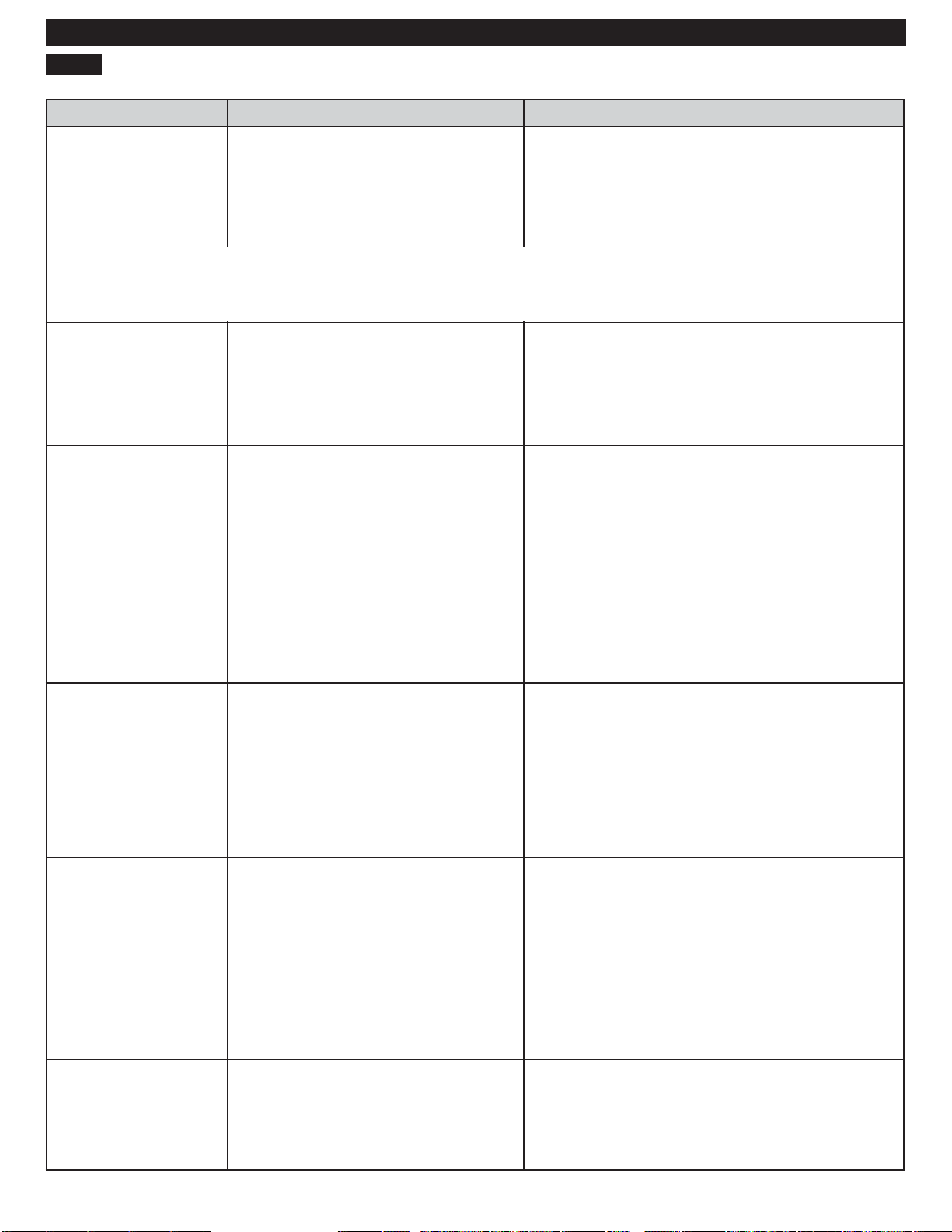
BEFORE CALLING FOR SERVICE
Problem Possible Cause Solutions
*CHECK VENT is
blinking
TROUBLESHOOTING GUIDE
Exhaust system is too long or has too
many turns/restrictions.
Install a shorter or straighter duct run. See the
Installation Instructions for details.
Partial blockage of the ductwork due
to lint buildup or other foreign object.
* This warning light does not indicate a dryer failure and is not covered by the dryer
warranty. Contact a duct cleaning service to set up an appointment to have your
exhaust system cleaned and inspected.
Dryer will not turn on Power cord is not properly plugged in.
House fuse is blo
has tripped, or power outage has
occurred.
Dryer does not heat House fuse is blown, circuit breaker
d, or power outage has
d together.
Greasy or dirty spots on
clothes
has trippe
occurred.
Gas supply or service is turned off
(gas models only).
Clean and dirty clothes are being
drie
wn, circuit breaker
Ductwork should be checked/cleaned
immediately. Dryer can be used in this condition,
but drying times will be longer and energy
consumption will increase.
Make sure that the plug is securely plugged into a
grounded outlet matching the dryer’s rating plate.
Reset circuit breaker or replace fuse. Do not
increase fuse capacity. If the problem is a
circuit overload, have it corrected by a qualifi ed
electrician.
Reset circuit breaker or replace fuse. Do not
increase fuse capacity. If the problem is a
circuit overload, have it corrected by a qualifi ed
electrician.
NOTE: Due to the design of electric dryers, it is
possible for a circuit problem to allow an electric
dryer to run without heat.
Confi rm that the house gas shutoff and the dryer
gas shutoff valves are both fully open. Even if gas
is not supplied to the dryer, it will run and no error
codes will display. Verify that other gas appliances
in the home are working normally.
Only use your dryer to dry clean items. Soil from dirty
clothes can transfer to the clean clothes in the same
or later loads.
Clothes were not properly cleaned
or rinsed before being placed in the
dryer.
Excess static in clothes
after dr
Drying time is not
onsistent
c
ying
Fabric softener is not used or used
incorrectly.
Clothes dried too long (over dried).
Drying synthetics, permanent press, or
synthetic blends.
Heat settings, load size, or dampness
of clothing is not consistent.
Stains on dried clothes could be stains that
weren’t removed during the washing process.
Make sure that clothes are being completely
cleaned or rinsed according to the instructions for
your washer and detergent. Some diffi cult soils
may require pre-treating prior to washing.
Use a fabric softener to reduce static
electricity. Be sure to follow the fabric softener
manufacturer’s instructions.
Overdrying a load of laundry can cause a buildup
of static electricity. Adjust settings and use a
shorter drying time, or use AUTO DRY cycles.
These fabrics are naturally more prone to static
buildup. Try using fabric softener, or use DAMP
DRY and/or shorter TIMED DRY time settings.
The drying time for a load will vary depending on the type
of heat used (electric, natural gas, or LP gas), the size of the
load, the type of fabrics, the wetness of the clothes, and
the condition of the exhaust duct and lint filter. Even an
unbalanced load in the washer can cause poor spinning,
resulting in wetter clothes which will take longer to dry.
29
Page 30
TROUBLESHOOTING GUIDE
BEFORE CALLING FOR SERVICE (continued)
Problem Possible Cause Solutions
Clothes take too long to
dry
Exhaust ducts are blocked, dirty, or
duct run is too long.
Confi rm that the exhaust duct is properly
confi gured and free of debris, lint, and
obstructions. Make sure that outside wall
dampers can open properly and are not
blocked, jammed, or damaged.
Load is not properly sorted.
Large load of heavy fabrics.
Dryer controls are not set properly.
Lint fi lter needs to be cleaned.
House fuse is blown, circuit breaker has
tripped, or power outage has occurred.
Separate heavy items from lightweight items.
Larger and heavier items take longer to dry.
Light items in a load with heavy items can fool
the sensor because the light items dry faster.
Heavy fabrics take longer to dry because they
tend to retain more moisture. To help reduce
and maintain more consistent drying times for
large and heavy fabrics, separate these items
into smaller loads of a consistent size.
Use the appropriate control settings for the
type of load you are drying. Some loads
may require an adjustment of the DRY LEVEL
setting for proper drying.
Remove the lint from the fi lter before every
load. With the lint removed, hold the fi lter up to
a light to see if it is dirty or clogged. If it looks
dirty, follow the cleaning instructions in the Care
and Cleaning section. With some loads that
produce high amounts of lint, such as new bath
towels, it may be necessary to pause the cycle
and clean the fi lter during the cycle.
Reset the circuit breaker or replace the fuse.
Do not increase fuse capacity. If the problem
is a circuit overload, have it corrected by a
qualifi ed electrician.
Dryer is overloaded.
Dryer is underloaded.
Clothes are wrinkled Clothes dried too long (overdried).
Clothes left in dr
cycle ends.
Clothes are shrinking Garment care instructions are not being
follo
wed.
yer too long after
NOTE: Due to the design of electric dryers, it
is possible for a circuit problem to allow an
electric dryer to run without heat.
Divide extra large loads into smaller loads for
better drying performance and effi ciency.
If you are drying a very small load, add a
few extra items to ensure proper tumbling
action. If the load is very small and you are
using AUTO DRY cycles, the electronic control
cannot properly sense the dryness of the load
and may shut off too soon. Use TIMED DRY or
add some extra wet clothes to the load.
Overdrying a load of laundry can lead to
wrinkled clothes. Try a shorter drying time or
DAMP DRY setting and remove items while
they still retain a slight amount of moisture.
Use the WRINKLE GUARD option. This feature
will tumble the clothes briefl y every few minutes
for up to 150 minutes to help prevent wrinkling.
To avoid shrinking your clothes, always consult
and follow fabric care instructions. Some
fabrics will naturally shrink when washed.
Other fabrics can be washed but will shrink
when dried in a dryer. Use a low or no heat
setting.
30
Page 31
BEFORE CALLING FOR SERVICE (continued)
Problem Possible Cause Solutions
Display shows error
code: tE1 or tE2
Lint on clothes Lint fi
Temperature sensor failure. Turn off the dryer and call for service.
lter not cleaned properly.
TROUBLESHOOTING GUIDE
Remove the lint from the fi lter before every load.
With the lint removed, hold the fi lter up to a light
to see if it is dirty or clogged. If it looks dirty,
follow the cleaning instructions in the Care and
Cleaning Section. With some loads that produce
high amounts of lint, it may be necessary to clean
the fi lter during the cycle.
Buttons are disabled or
CL shows in display
Light does not turn on
when door is opened
Laundry not sorted properly.
Excess static in clothes.
Dryer is overloaded.
Tissue, paper, etc., left in pockets.
CONTROL LOCK function is engaged. Press and hold the TOUCH UP button for fi ve
Dryer has been off for more than four
minutes and the light is disabled.
Some fabrics are lint producers (i.e., a fuzzy white
cotton towel) and should be dried separately from
clothes that are lint trappers (i.e., a pair of black
linen pants).
Use a fabric softener to reduce static electricity.
Be sure to follow the manufacturer’s instructions.
Overdrying a load of laundry can cause a buildup
of static electricity. Adjust settings and use a
shorter drying time, or use AUTO DRY cycles.
Divide extra large loads into smaller loads for drying.
Check pockets thoroughly before washing and
drying clothes.
seconds to activate or deactivate the function.
Press the POWER button to turn on the dryer, which
will enable the drum light.
31
Page 32
WARRANTY
Kenmore Limited Warranty
WITH PROOF OF SALE the following warranty coverage applies when this appliance is correctly installed,
operated and maintained according to all supplied instructions.
One Year on Appliance
FOR ONE YEAR from the date of sale this appliance is warranted against defects in material or workmanship.
A defective appliance will receive free repair. If the appliance cannot be repaired it will be replaced free of
charge.
Lifetime on Dryer Drum and Baffl es
FOR AS LONG AS IT IS USED from the date of sale, a free replacement will be supplied for a defective dryer
drum, including baffl es.* If the defect appears within the fi rst year, a new drum or baffl es will be installed at no
charge. If the defect appears after the fi rst year, a new drum or baffl es will be supplied but not installed at no
charge. This Lifetime warranty covers only the dryer drum and baffl es, and does not apply to any other related
component or mechanism. You are responsible for the labor cost of drum or baffl es installation after the fi rst year
from the date of sale. *Defects must be verifi ed by a Sears authorized service technician.
For warranty coverage details to obtain free repair or replacement, visit the web page:
www.kenmore.com/warranty
This warranty applies for only 90 DAYS from the sale date in the United States if this appliance is ever used for
other than private household purposes.
This warranty covers ONLY defects in material and workmanship, and will NOT pay for:
1. Expendable items that can wear out from normal use, including but not limited to fi lters, belts, bags or screw-
in base light bulbs.
2. A service technician to clean or maintain this appliance, or to instruct the user in correct appliance
installation, operation and maintenance.
3. Service calls to correct appliance installation not performed by Sears authorized service agents, or to repair
problems with house fuses, circuit breakers, house wiring, and plumbing or gas supply systems resulting from
such installation.
4. Damage to or failure of this appliance resulting from installation not performed by Sears authorized service
agents, including installation that was not in accord with electrical, gas or plumbing codes.
5. Damage to or failure of this appliance, including discoloration or surface rust, if it is not correctly operated
and maintained according to all supplied instructions.
6. Damage to or failure of this appliance, including discoloration or surface rust, resulting from accident,
alteration, abuse, misuse or use for other than its intended purpose.
7. Damage to or failure of this appliance, including discoloration or surface rust, caused by the use of
detergents, cleaners, chemicals or utensils other than those recommended in all instructions supplied with the
product.
8. Damage to or failure of parts or systems resulting from unauthorized modifi cations made to this appliance.
9. Service to an appliance if the model and serial plate is missing, altered, or cannot easily be determined to
have the appropriate certifi cation logo.
Disclaimer of implied warranties; limitation of remedies
Customer’s sole and exclusive remedy under this limited warranty shall be product repair or replacement as
provided herein. Implied warranties, including warranties of merchantability or fi tness for a particular purpose, are
limited to one year or the shortest period allowed by law. Seller shall not be liable for incidental or consequential
damages. Some states and provinces do not allow the exclusion or limitation of incidental or consequential
damages, or limitation on the duration of implied warranties of merchantability or fi tness, so these exclusions or
limitations may not apply to you.
This warranty applies only while this appliance is used in the United States.
This warranty gives you specifi c legal rights, and you may also have other rights which vary from state to state.
Sears Brands Management Corporation, Hoff man Estates, IL 60179
32
Page 33

NOTE
33
Page 34
Kenmore ®
®
Customer Care Hotline
To schedule in-home repair service
or order replacement parts
Para pedir servicio de reparación
a domicilio, y ordenar piezas
1-844-553-6667
www. kenmore. com
 Loading...