


REFRIGERATOR SERVICE MANUAL
CAUTION
BEFORE SERVICING THE UNIT,
READ THE SAFETY PRECAUTIONS IN THIS MANUAL.
Model #s:
795.71022.010
795.71023.010
795.71024.010
795.71026.010
795.71029.010
P/No. MFL63273703

CONTENTS |
|
SAFETY PRECAUTIONS ....................................................................................................................................................... |
2 |
1. SPECIFICATIONS ........................................................................................................................................................... |
3-4 |
2. PARTS IDENTIFICATION .................................................................................................................................................. |
5 |
3. DISASSEMBLY ............................................................................................................................................................. |
6-17 |
REMOVING AND REPLACING REFRIGERATOR DOORS ............................................................................................... |
6 |
DOOR .............................................................................................................................................................................. |
7-8 |
DOOR ALIGNMENT ........................................................................................................................................................... |
8 |
FAN AND FAN MOTOR(Evaporator) .................................................................................................................................. |
8 |
DEFROST CONTROL ASSEMBLY .................................................................................................................................... |
9 |
LAMP .................................................................................................................................................................................. |
9 |
MULTI DUCT .................................................................................................................................................................... |
10 |
MAIN PWB ........................................................................................................................................................................ |
10 |
DISPENSER ....................................................................................................................................................................... |
10 |
DISPLAY PWB REPLACEMENT....................................................................................................................................... |
11 |
FUNNEL REPLACEMENT.................................................................................................................................................. |
11 |
SUB PWB FOR WORKING DISPENSER........................................................................................................................... |
11 |
DUCT DOOR REPLACEMENT ......................................................................................................................................... |
11 |
ICE CORNER DOOR REPLACEMENT.............................................................................................................................. |
12 |
ICEMAKER ASSEMBLY ..................................................................................................................................................... |
12 |
AUGER MOTOR COVER ................................................................................................................................................... |
12 |
HOW TO REMOVE A DOOR ICE BIN................................................................................................................................ |
13 |
HOW TO INSERT A DOOR ICE BIN .................................................................................................................................. |
13 |
HOW TO REMOVE AND REINSTALL THE PULLOUT DRAWER................................................................................ |
14-15 |
WATER VALVE DISASSEMBLY METHOD........................................................................................................................ |
16 |
FAN AND FAN MOTOR DISASSEMBLY METHOD........................................................................................................... |
16 |
PULL OUT DRAWER.......................................................................................................................................................... |
17 |
4. ADJUSTMENT ............................................................................................................................................................ |
18-20 |
COMPRESSOR ................................................................................................................................................................ |
18 |
INTRODUCTION OF E-LINEAR COMPRESSOR........................................................................................................ |
18-20 |
5. CIRCUIT DIAGRAM ......................................................................................................................................................... |
21 |
6. TROUBLESHOOTING ...................................................................................................................................................... |
22 |
7. PCB PICTURE.............................................................................................................................................................. |
23-24 |
8. TROUBLESHOOTING WITH ERROR DISPLAY......................................................................................................... |
25-33 |
9. TROUBLESHOOTING WITHOUT ERROR DISPLAY................................................................................................... |
34-42 |
10. REFERENCE ............................................................................................................................................................... |
43-48 |
11. COMPONENT TESTING INFORMATION .................................................................................................................. |
49-57 |
12. TROUBLESHOOTING ................................................................................................................................................ |
58-64 |
13. OPERATION PRINCIPLE AND REPAIR METHOD OF ICEMAKER.......................................................................... |
65-67 |
14. DESCRIPTION OF FUNCTION & CIRCUIT OF MICOM............................................................................................. |
68-71 |
SAFETY PRECAUTIONS |
|
Please read the following instructions before servicing your refrigerator.
1.Unplug the power before handling any elctrical componets.
2.Check the rated current, voltage, and capacity.
3.Take caution not to get water near any electrical components.
4.Use exact replacement parts.
5.Remove any objects from the top prior to tilting the product.
- 2 -

1. SPECIFICATIONS
1-1 DISCONNECT POWER CORD BEFORE SERVICING
IMPORTANT - RECONNECT ALL GROUNDING DEVICES
All parts of this appliance capable of conducting electrical current are grounded. If grounding wires, screws, straps, clips, nuts or washers used to complete a path to ground are removed for service, they must be returned to their original position and properly fastened.
1-2 IMPORTANT NOTICE
This information is intended for use by individuals possessing adequate backgrounds of electrical, electronic and mechanical experience. Any attempt to repair a major appliance may result in personal injury and property damage. The manufacturer or seller cannot be responsible for the interpretation of this information, nor can it assume any liability in connection with its use.
1-3 ELECTRICAL SPECIFICATIONS
Temperature Control (Freezer Compartment) .. -6°F to +8°F Defrost Control .....Total Comp Running Time: 7 hrs~50 hrs
Defrost Thermostat ...................................................... |
46°F |
Electrical Rating : 115VAC, 60Hz ................................ |
5.2 A |
Maximum Current Leakage ...................................... |
0.5 mA |
Maximum Ground Path Resistance ................... |
0.14 Ohms |
Energy Consumption ....................... |
25 cu.ft. 547 (E/STAR) |
1-4 NO LOAD PERFORMANCE CONTROL POSITION : MID/MID
And Ambient of : ................ |
70°F ................................. |
90°F |
Fresh Food, °F .................. |
33°F to 41°F ........ |
33°F to 41°F |
Frozen Food, °F ................ |
-4°F to +4°F ......... |
-4°F to +4°F |
Percent Running Time ...... |
35%-45% ................. |
50°F-70°F |
1-5 REFRIGERATION SYSTEM
Minimum Compressor Capacity Vacuum |
................ 21 MIN. |
Minimum Equalized Pressure |
|
@ 70°F ............................................................ |
49 PSIG |
@ 90°F ............................................................ |
56 PSIG |
Refrigerant R134a ................................................... |
4.94 oz. |
Compressor ....................................................... |
956 BTU/hr |
1-6 INSTALLATION
Clearance must be provided at top, sides and rear of the refrigerator for air circulation.
AT REAR ....................................................................... 2 in
1-7 REPLACEMENT PARTS
|
25 cuft |
|
795.71022.010 |
|
795.71023.010 |
|
795.71024.010 |
|
795.71026.010 |
|
795.71029.010 |
Defrost Thermostat ....................................... |
6615JB2005H |
Defrost Heater ............................................... |
5300JK1005D |
Evaporator Fan Motor ................................... |
4681JB1027C |
|
(4681JK1004E) |
Capacitor (Running) ..................................... |
EAE58905701 |
Compressor (Hi-Side) ................................... |
TCA34649901 |
Evaporator (Lo-Side) ..................................... |
5421JJ1003B |
Condenser ................................................... |
ACG72915205 |
Dryer ............................................................. |
5851JA2007E |
Condenser Fan Motor ................................... |
4681JB1029D |
Temperature Control ............................ |
ACQ36820516(SW) |
|
ACQ36820517(STS) |
|
ACQ36820518(TI) |
|
ACQ36820519(WB) |
|
ACQ36820520(BI) |
Main Control ................................................. |
EBR67348003 |
Ice Fan Motor ................................................ |
4681JB1027E |
1-8 AIR FLOW / CIRCULATION D’AIR
- 3 -

|
|
|
|
|
|
|
|
|
|
|
|
|
|
|
|
|
|
|
|
|
|
|
|
|
|
|
|
|
|
|
|
|
|
|
|
|
|
|
|
|
|
|
|
|
|
|
|
|
|
|
|
|
|
|
|
|
|
|
|
|
|
|
|
|
|
Description |
|
795.710* |
|
|
|
|
||||
Depth w/ Handles |
A |
34 1/4 in |
||||
|
|
|
||||
Depth w/ Handles |
B |
31 3/4 in |
||||
|
|
|
||||
Depth w/ o Door |
C |
27 7/8 in |
||||
|
|
|
||||
Depth (Total with Door Open) |
D |
46 1/2 in |
||||
|
|
|
||||
Height to Top of Case |
E |
68 3/8 in |
||||
|
|
|
||||
Height to Top of Door Hinge |
F |
69 3/4 in |
||||
|
|
|
||||
Width |
G |
35 3/4 in |
||||
|
|
|
||||
Width (door open 90 deg. w/o handle) |
H |
39 1/4 in |
||||
|
|
|
||||
Width (door open 90 deg. w/ handle) |
I |
44 1/4 in |
||||
|
|
|
|
|
|
|
- 4 -
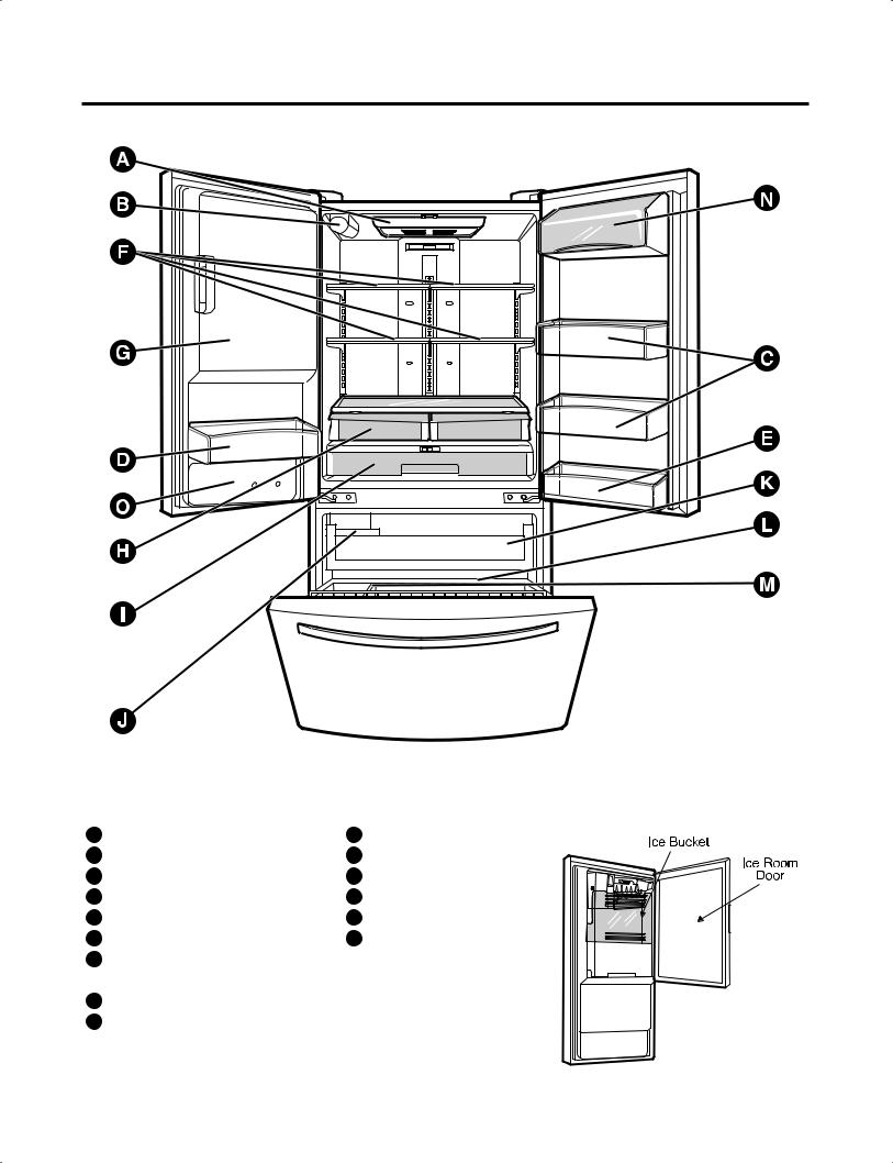
2. PARTS IDENTIFICATION
Use this page to become more familiar with the parts and features. Page references are included for your convenience. NOTE : This guide covers several different models. The refrigerator you have purchased may have some or all of the items listed below. The locations of the features shown below may not match your model.
Light |
|
Filter (Inside) |
Pull out Drawer |
Modular Door Bins |
Durabase |
Fixed door bin |
Divider |
Fixed door bin |
Dairy Bin |
Refrigerator Shelves |
O Water Tank Cover |
Ice Room |
|
(Ice Maker and Ice Bucket) |
|
Humidity Controlled Crisper |
|
I Glide’N’Serve |
|
- 5 -
3. DISASSEMBLY
3-1 REMOVING AND REPLACING REFRIGERATOR DOORS
 CAUTION : Before you begin, unplug the refrigerator and remove the food and bins from the doors.
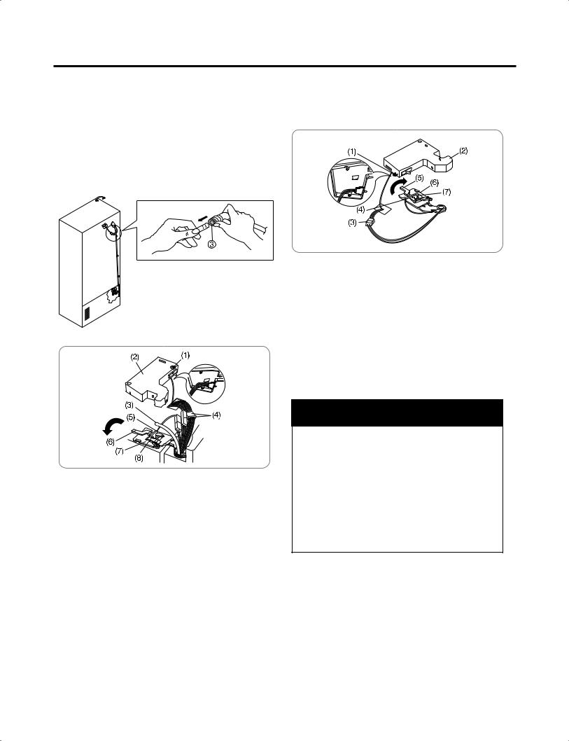
To remove the left refrigerator door:
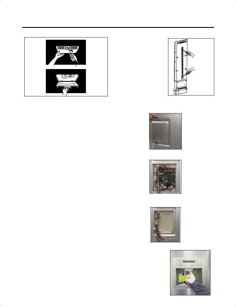
On the back of the refrigerator, press back on the release ring of the fitting (see 3 in figure below) and pull out the water tube in the direction of the arrow.
1.Open the door. Remove the top hinge cover screw (1).
2.Use a flat-head screwdriver to pry back the hooks (not shown) on the front underside of the cover (2).
Lift up the cover.
3.Remove the cover. Pull out the tube (3).
4.Disconnect all the wire harnesses (4).
5.Remove the grounding screw (5).
6.Rotate hinge lever (6) counterclockwise.
Lift the top hinge (7) free of the hinge lever latch (8).
 CAUTION : When lifting the hinge free of the latch, be careful that the door does not fall forward.
7.Remove the door by lifting it off the middle hinge pin, located at the bottom of the door.
8.Place the door on a soft, smooth surface with the inside up to prevent damage.
To remove the right refrigerator door:
1.Open the door. Remove the top hinge cover screw (1). Lift up cover (2).
2.Remove cover.
3.Disconnect wire harness (3).
4.Remove the grounding screw (4).
5.Rotate hinge lever (5) clockwise.
Lift top hinge (6) free of hinge lever latch (7).
6.Remove the door by lifting it off the middle hinge pin, located at the bottom of the door.
7.Place the door on a soft, smooth surface with the inside up to prevent damage.
 CAUTION : When lifting the hinge free of the latch, be careful that the door does not fall forward.
 WARNING
Electrical Shock Hazard
 Disconnect electrical supply to the refrigerator before installing. Failure to do so could result in death or serious injury.
 Do not put hands or feet or other objects into the air vents, base grille, or bottom of the refrigerator. You may be injured or receive an electrical shock.
 Be careful when you work with the hinge, base grille, and stopper. You may be injured.
- 6 -

3-2 DOOR
 Door Gasket Removal
1.Remove door frame cover
Starting at top of cover and working down, snap cover out and away from door.
Frame Cover 
Handle
Figure 1
2.Remove gasket bracket clips
There are two clips on each door. Start bracket removal near one of the middle clips.
1)Pull gasket back to expose gasket bracket clip and door frame.
2)Insert a flat tip screwdriver into seam between gasket bracket and door frame and pry back until clips snap out.
3)Continue prying back along seam until all clips snap out.
Gasket
Door Bracket Clip
Frame
Flat Tip
Screwdriver 
Gasket
Bracket
Figure 2
3.Remove gasket
Pull gasket free from gasket channel on the three remaining sides of door.
Figure 3
 Door Gasket Replacement
1.Insert gasket bracket clips
1)Insert gasket bracket edge beneath door frame edge.
2)Turn upper gasket bracket spring so that the spring ends are in the door channel.
3)Push in clip until you hear it snap securely into place.
Gasket
Bracket Clip
 Spring
Door
Frame
Correct |
Incorrect |
Figure 4
4)Push in remaining clip until you hear it snap securely into place.
Note : Make sure that no part of gasket bracket edge protrudes from beneath door frame edge.
2.Insert gasket into channel
1)Snap gasket assembly into the door bracket.
<Inserting the Gasket Assembly into the Bracket Door>
|
Correct |
Incorrect |
Figure 5 |
|
- 7 -
2)Press gasket into channels on the three remaining sides of door.
Figure 6
3. Replace door frame cover
Starting at top of cover and working down, snap cover back into door.
Figure 7
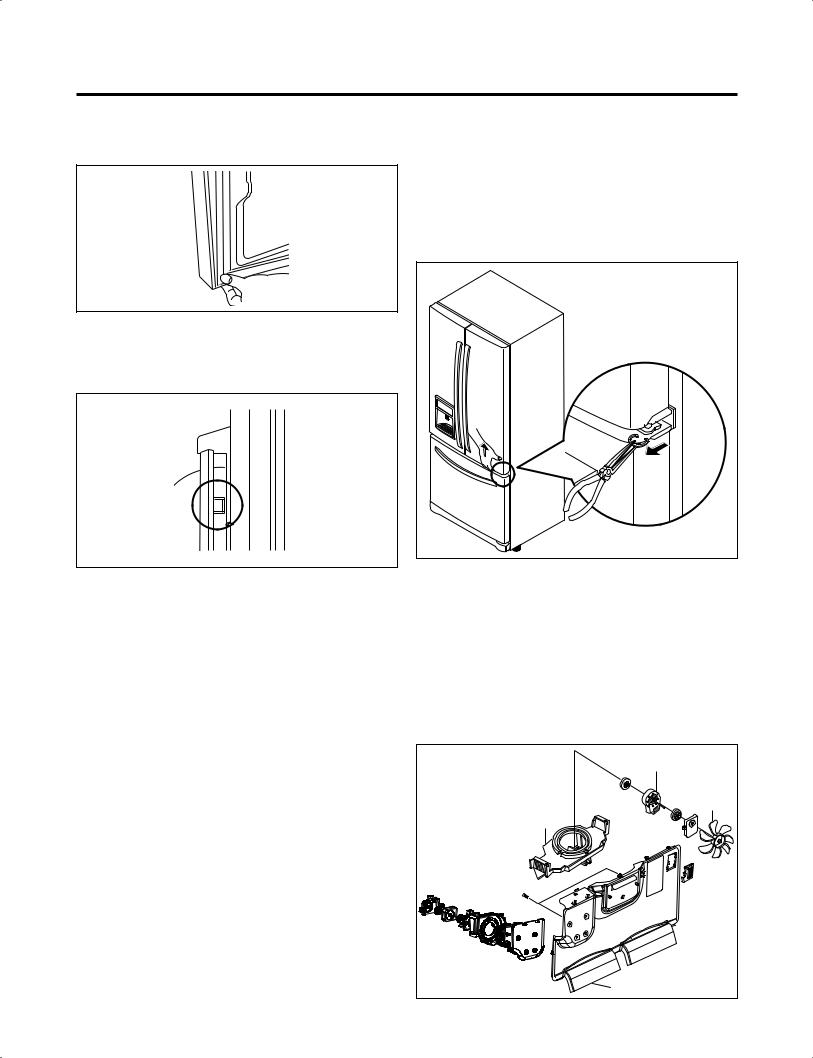
3-3 DOOR ALIGNMENT
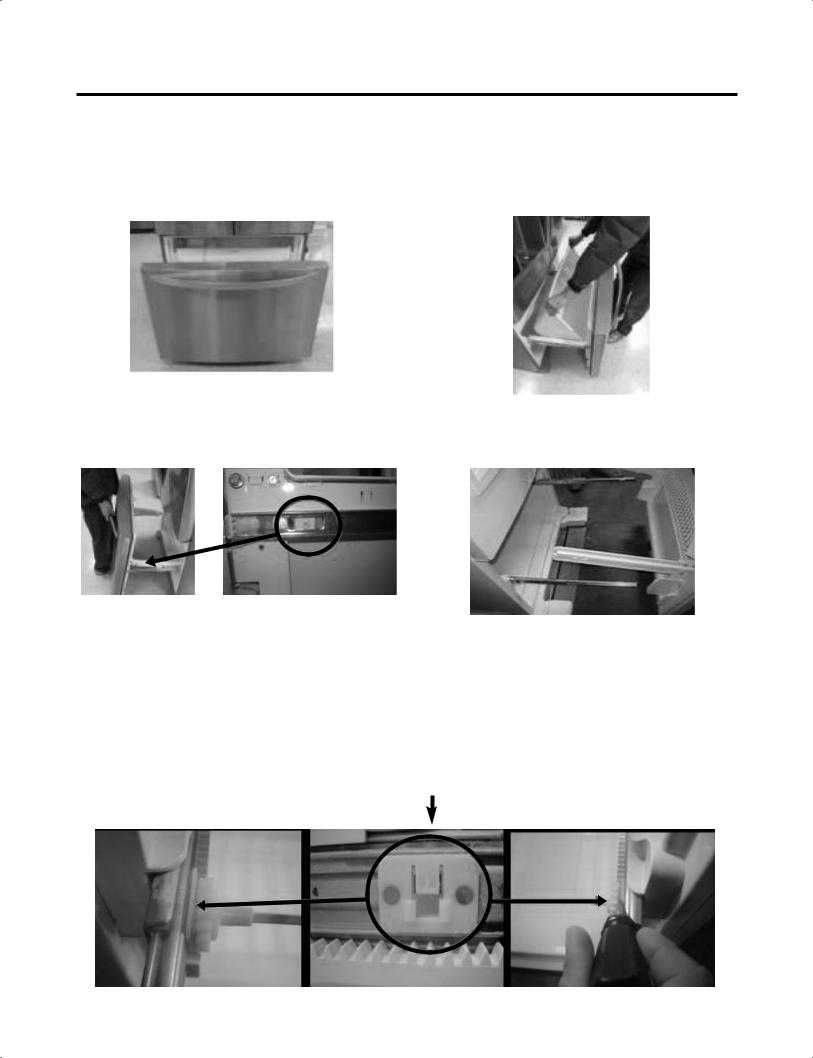
If the space between your doors is uneven, follow the instructions below to align the doors :
1.With one hand, lift up the door you want to raise at middle hinge.
2.With other hand, use pliers to insert snap ring as shown.
3.Insert additional snap rings until the doors are aligned. (Three snap rings are provided with unit.)
Figure 10 |
3-4 FAN AND FAN MOTOR(EVAPORATOR)
1.Remove the freezer shelf. (If your refrigerator has an icemaker, remove the icemaker first)
2.Remove the plastic guide for slides on left side by unscrewing phillips head screws.
3.Remove the grille by removing one screw and pulling the grille forward.
4.Remove the Fan Motor assembly by loosening 2 screws and disassembling the shroud.
5.Pull out the fan and separate the Fan Motor and Bracket.
FAN MOTOR |
|
BRACKET |
FAN |
|
|
MOTOR |
|
GRILLE |
Figure 11 |
- 8 - |
|
* Ice Fan Scroll Assembly Replacement
1)Remove the plastic guide for slides on left side by unscrewing phillips head screws.
2)Pull the grille forward as shown in the second picture.
3)Disconnect wire harness of the grille.
4)Remove the scroll assembly by loosening all screws.
(1) |
(2) |
(3) |
(4) |
3-5 DEFROST CONTROL ASSEMBLY
Defrost Control assembly consists of Defrost Sensor and FUSE-M.
The Defrost Sensor works to defrost automatically. It is attached to the metal side of the Evaporator and senses its temperature. At 46°F (8°C), it turns the Defrost Heater off. Fuse-M is a safety device for preventing over-heating of the Heater when defrosting.
1.Pull out the grille assembly. (Figure 10)
2.Separate the connector with the Defrost Control assembly and replace the Defrost Control assembly after cutting the Tie Wrap. (Figure 11)
GRILLE ASSEMBLY |
DEFROST-CONTROL |
|
ASSEMBLY |
3-6 LAMP
Unplug Refrigerator, or disconnect power at the circuit breaker.
If necessary, remove top shelf or shelves.
3-6-1 Refrigerator Compartment Lamp
1)Release 2 screws.
2)Hold both ends with your both hands and pull it downward to remove it.
3)Use a flat tool as shown below to remove the cover lamp.
Figure 12
4)As shown below, use a flat tool to remove the cover lamp.
Figure 13
Cover, Lamp |
LED, Assembly Case Lamp |
|
Figure 14 |
Figure 10 |
Figure 11 |
- 9 -
To change freezer light
NOTE: Some models have LED interior lighting and service should be performed by a qualified technician.
1.Unplug refrigerator power cord form outlet.
2.Using a flat instrument, gently pry the lamp cover loose in the front as shown. Rotate downward to remove the rear tabs.
3.Make sure the bulb is cool to the touch. Turn the bulb counterclockwise to remove.
4.Replace with a new 60-watt appliance bulb.
5.Insert tabs on back of cover into slots in freezer ceiling. Push cover up to snap front into place.
3-7 MULTI DUCT
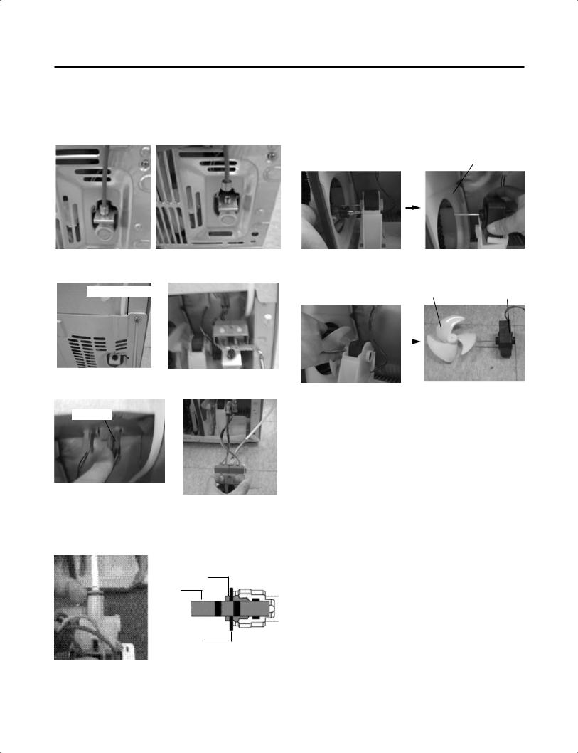
1. Remove the upper and lower Caps by using a flat screwdriver, and remove 2 screws. (Figure 17)
2. Disconnect the lead wire on the bottom position.
Figure 17
3-8 MAIN PWB
1) Loosen the 4 screws on the PWB cover.
2) Remove the PWB cover
3)Disconnect wire harness and replace the main PWB in the reverse order of removal.
3-9 DISPENSER
1)Disconnect funnel and button assembly by pulling down and forward.
- 10 -
2)Hold the left and right side of the “Cover Assembly, dispenser” as shown in the picture, and pull and remove it. The cover dispenser is attached with a hook.
 CAUTION : When replacing the dispenser cover in the reverse order of removal, be careful that the lead wire does not come out and the water tube is not pinched by the dispenser cover, as shown in the picture below.
3-10 DISPLAY PWB REPLACEMENT
1) Pull up and out on the dispenser cover to remove.
2) Follow the steps in the pictures
3-11 FUNNEL REPLACEMENT
1)Pull up and out on the dispenser cover to remove.
2)Disconnect the wire harness.
3)Replace in reverse order.
3-12 SUB PWB FOR WORKING DISPENSER
1) Loosen the screw on the sub PWB.
2)Pull the sub PWB down.
3)Disconnect the wire harness and replace the sub PWB in the reverse order of removal.
3-13 DUCT DOOR REPLACEMENT
1)Pull up and out on the dispenser cover to remove.
2)Disconnect the wire harness.
3)Remove the funnel
4)Replace in reverse order.
- 11 -

3-14 ICE CORNER DOOR REPLACEMENT
1)Loosen the front screw as shown in the picture.
2)Lift up the hinge with one hand.
3)Pull out the Ice Corner Door with the other hand.
3-15 ICEMAKER ASSEMBLY
1) Loosen two screws as shown in the first picture.
2)Disconnect the wire harness & ground screw replace theIcemaker assembly in the reverse order of removal.
3-16 AUGER MOTOR COVER
1)After removing the icemaker remove the (5) stainless screws holding the auger motor cover, shown in the picutres below.
2) Grip the bottom of motor cover assembly and pull out it.
3)Disconnect wire harness of motor cover assembly. There is a auger motor on the back, as shown in the picture.
Auger Motor
3) It separates a ground connection screw.
- 12 -

3-17 HOW TO REMOVE A DOOR ICE BIN
1) Grip the handles, as shown in the picture.
2) Lift the lower part slightly.
3) Take the Ice Bin out slowly.
3-18 HOW TO INSERT A DOOR ICE BIN
1)Insert the Ice Bin, slightly tilting it to avoid touching the Icemaker. (especially, ice maker lever)
 Insert the ice bucket carefully avoid contacing the automatic shut off arm.
- 13 -
3-19 HOW TO REMOVE AND REINSTALL THE PULLOUT DRAWER
3-19-1 Follow Steps to Remove
Step 1) Open the freezer door. |
Step 2) Remove the lower basket. |
Step 3) Remove the two screws from the guide rails (one from each side).
Step 4) Lift the freezer door up to unhook it from the rail support and remove.
Pull both rails to full extension.
Step 5) First : Remove the gear from the left side first by releasing the tab behind the gear, place a screwdriver between the gear and the tab and pull up on the gear.
Second : Remove the center rail.
Third : Remove the gear from the right side by following the same steps for the left side.
NOTE : THIS TAB MUST BE PUSHED IN TO RELEASE THE GEAR.
- 14 -

3-19-2 Follow Steps to Reinstall
Step 1) Reinstall the right side gear into the clip.
Step 2) Insert the rail into the right side gear. Gears do not need to be perpendicular to each other.
Step 4) The rail system will align itself by pushing the rails all the way into the freezer section.
Pull the rails back out to full extension.
Step 6) Reinstall the two screws into the guide rails (one from each side).
Step 3) Insert the rail into the left side gear, and insert the gear into the clip.
Step 5) Reinstall the freezer door by inserting the rail tabs into the guide rail.
Step 7) Reinstall the lower basket, and close the freezer door.
- 15 -
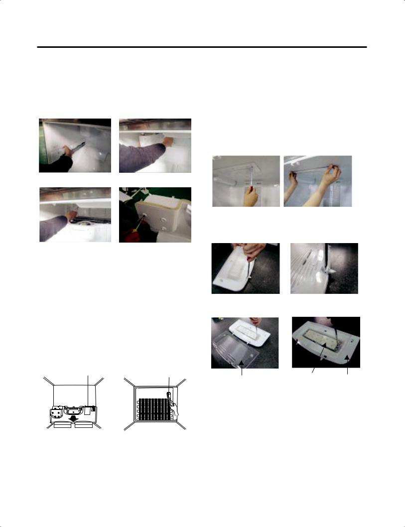
3-20 WATER VALVE DISASSEMBLY METHOD
1)Turn off the water. Then separate the water line from the valve.
2) Separate the Mechanical Cover and Valve Screw.
Mechanical Cover
3) Separate the housing and pull out the valve.
Housing
4)Lay a dry towel on the floor and get ready to spill water from the water filter. Pull out the Cilp. Then press te collet to separate the tube from the connector and pour out the water until emptied.
Collet
Tube
Insert Line 
Clip
3-21 FAN AND FAN MOTOR DISASSEMBLY METHOD
1)Using a short screwdriver, loosen one SCREW in DRAIN PIPE ASSEMBLY and one connected to the MOTOR COVER.
MOTOR COVER
2)Pull and separate the FAN ASSEMBLY and MOTOR turning counterclockwise based on the MOTOR SHAFT.
|
FAN ASSEMBLY |
MOTOR |
|||
|
|
|
|
|
|
|
|
|
|
|
|
|
|
|
|
|
|
The assembly is in the reverse order of the disassembly and take special care for the following details.
1.Be careful not to bend the tube during assembly.
2.Press the WATER DISPENSER button until water pours out and check for leakage in the CONNECTOR TUBE (It differs by the water pressure but usually takes about 2 minutes until water pours out.)
- 16 -

3-22 PULL OUT DRAWER
Separate the drawer, push the front left and right hooks in  direction to pull up and remove. Then gently lift and pull it out in
  direction.
3 |
2 |
1 |
To install, After pulling out both rails as much as possible, and insert an end of rib to the bracket  at left and right then gently push down both left and right side while checking the hook on the front part.
Hook
4
- 17 -

4. ADJUSTMENT
4-1 COMPRESSOR
4-1-1 Role
The compressor intakes low temperature and low pressure gas from the evaporator of the refrigerator and compresses this gas to high-temperature and high-pressure gas. It then delivers the gas to the condenser.
4-1-2 Note for Usage
(1)Be careful not to allow over-voltage and over-current.
(2)Do not drop or handle carelessly.
(3)Keep away from any liquid.
If liquid such as oil or water enters the Cover PTC Compressor may fail due to breakdown of their insulating capabilities.
(4)Always use the Parts designed for the compressor and make sure it is properly attached to the compressor. Parts may appear physically identical but could have different electrical ratings. Replace parts by part number and model number. Use only approved substitute parts.
4-1-3 REMOVE THE COVER PTC
(1) Remove the Cover Back M/C
(2) Loosen two screws on comp base
(3)Use a L-shaped flap tooll to pry off the cover
(4)Assembly in reverse order of disassembly
4-2 Introduction of E-Linear Compressor
 E-Linear compressor is run by mechanical part design through automatically varying the cooling power. The main parts consist of compressor and Sub PCB which controls the compressor. PCB authorizes constant voltage and constant frequency to the compressor and protects it.
4-2-1 Control of Compressor Block Diagram
|
|
|
PWM |
|
|
Linear |
||||
Compressor Controller |
Signal |
|
Inverter |
|
|
|||||
Frequ |
|
|
Comp |
|||||||
|
|
|
|
|
|
|
||||
|
|
|
-ency |
|
|
|
|
|
|
|
|
|
|
|
|
|
|
|
|
||
|
|
|
|
|
|
|
|
|
|
|
|
|
|
|
|
|
|
|
|
|
|
|
|
|
|
|
DC link |
|
|
Vcap Voltage |
||
|
|
|
|
|
Voltage |
|
|
|||
|
|
|
|
|
|
|||||
|
|
|
|
|
|
|
|
|
||
|
|
|
|
|
|
|
|
|
|
|
Main |
Counter elec- |
Micom |
tromotive force |
Calculate counter electromotive force
Control Block Diagram of Compressor
4-2-2 Compressor operating pattern
 Drive half stroke after turning on initial power for 30 seconds. Then, slowly increase stroke and reach target input. Once reaching the target input, input naturally changes according to refrigerator load without any special control.
|
Comp. input |
|
|
|
|
Interval 1) Half stroke interval - after initial running, stay at the initial value for 30 seconds
Interval 2) Running interval - Increase at every 0.8 till it reaches the target input; it takes about
3 Minutes and 45 seconds.
Interval 3) CVCF interval - Run by target voltage and main operating frequency and the input naturally changes according to refrigerator load
- 18 -

4-2-3 Compressor protection logic
 Since linear Comp conducts linear reciprocating motion, we have protection logic for compressor, motor and PCB as the below.
-Stroke Trip
During the operation, if stroke is above the target value, decrease the target volt by 3V.
-Current Trip
Current trip is set in order to protect compressor mechanical part and drive from the overcurrent that might arise during the operation.
Check the current for every 416.7us and if the Trip exceeds 1.86Arms more than three times at Comp ON, forcibly stop and restart six minutes later.
-Lock Piston Trip
If stroke is under 5mm even if the current is more than 14Arms, Take it as ‘piston lock’ and restart after 2’30” of Comp OFF. Check the current and stroke for every 416.7us and if the condition fits more than three times at Comp ON, the Trip occurs.
-IPM fault Trip
It occurs if FO signal received from IPM is LOW. For every 416.7us, check whether FO signal is LOW. The trip occurs if it is found three times during the five periods(83ms).
4-2-4 Compressor problems diagnosis
 When there is a problem or failure with the `operation, you are kindly recommended to check it as follows ;
1) Check to normality by measurement of resistance
Measure the resistance between poles of the hermetic terminal (as shown picture) with a multi-tester. (measurement several minutes after power off)
P : Power Line |
|
C : Common Line |
Multi-tester |
|
Case 1-1
If the measured values lie in the normal resistance range as in the table below,
 Compressor is normal.
Case 1-2
If the measured values are above several M or a infinity,
  Wire is disconnected in the shell.
Case 1-3
If the measured values are excessively of small number,  There is short somewhere in the shell.
 Normal resistance range (measured at ambient temperature 23
 )
)
Resistance
FC75LANE |
6~8 |
 According to ambient temperature or operation situation, the values could show a little deviation.
- 19 -

2) Check to normality by measurement of Voltage
Measure the resistance between pin of the connector (as shown picture) with a multi-tester.
<Fig. 1> |
<Fig. 1> |
Standard for normality
-In order to decide whether compressor operating is normal or not, check the output transfer during the refrigerator operation.
-After input the initial power and compressor operates, wait for 10 minutes to estimate.
-Compressor operation may be diagnosed as normal if the voltage falls between 145V and 180V.
Warning
1.Please be cautious of electric shock and short (it is estimated after turning on initial power).
2.If the voltage is estimated less than 80V, it is diagnosed as bad.
3) Check problems by LED On & Off Count _ (Sub PCB)
If compressor protection logic is running, LED Lamp’s blinking frequency of sub PCB, which takes in charge of control, can help estimate the protection logic’s symptoms and the cause of its problems.
Trip name |
Led Times |
Comp Off Time |
Stroke Trip |
2 |
1min |
Current Trip |
6 |
6min |
|
|
|
Lock Piston Trip |
5 |
2min 30sec |
|
|
|
IPM fault trip |
7 |
20sec |
|
|
|
-Current Trip  PCB defects or Cycle clogging maybe the causes. After estimating winding resistance, estimate compressor operation voltage to check if there is any problem and take actions to repair cycle at replacement of compressor.
-Stroke Trip  can occur when the surrounding temperature is high, C-Fan, F-Fan and so on are constrained, or when cycle problems, such as moisture blocking or compressor defect, are related.
-Lock Piston Trip  Since compressor itself can be a potential cause of a defect, estimate the compressor resistance value according to #1’s compressor winding value estimation method and estimate the #2’s compressor operation voltage to decide whether it is defective or not
(Before replacement of compressor, replace PCB and conduct the replacement of compressor during compressor replacement)
-IPM fault Trip  Replace sub PCB since there is high chance that it is caused by sub PCB’s part defect.
- 20 -

5. CIRCUIT DIAGRAM
- 21 -

6. TROUBLESHOOTING
ERROR CODE on display panel
|
Error Detection |
Error Display |
|
|
||
NO |
|
|
Error Generation Factors |
Remark |
||
Freezer |
Ref. |
|||||
Category |
||||||
|
Temperature |
Temperature |
|
|
||
|
|
|
|
|||
|
|
|
|
|
|
|
1 |
Normality |
|
|
None |
Normal operation of Display |
|
|
|
|
|
|
|
|
2 |
Freezer Sensor |
Er |
FS |
Short or Disconnection of |
|
|
Error |
Freezer Sensor |
|
||||
|
|
|
|
|||
|
|
|
|
|
|
|
3 |
Refrigerator |
Er |
rS |
Short or Disconnection of |
|
|
Sensor Error |
Refrigerator Sensor |
Each Sensor have to check |
||||
|
|
|
||||
|
|
|
|
|
||
|
|
|
|
|
disconnection |
|
4 |
Defrosting Sensor |
Er |
dS |
Short or Disconnection of |
||
|
||||||
Error |
Defrosting Sensor |
|
||||
|
|
|
|
|||
|
|
|
|
|
|
|
5 |
Icing Sensor Error |
Er |
IS |
Short or Disconnection of |
|
|
Icing Sensor |
|
|||||
|
|
|
|
|
||
|
|
|
|
|
|
|
|
|
|
|
Even though it is passed |
Temperature Fuse |
|
6 |
Poor Defrosting |
Er |
dH |
1hour since then Defrosting, |
Disconnection, Heater |
|
if Defrosting sensor is not |
disconnection, DRAIN Jam, |
|||||
|
|
|
|
|||
|
|
|
|
over 46°F(8°C), it is caused |
Poor Relay for Heater |
|
|
|
|
|
|
|
|
|
Abnormality of |
|
|
It is caused when F/B signal |
Poor BLDC Motor connection, |
|
7 |
Brushless DC |
Er |
IF |
isn’t over 65 seconds during |
DRIVE IC, and TR |
|
FAN Motor for Ice |
Brushless DC FAN motor |
|
||||
|
|
|
|
|||
|
Making |
|
|
operating |
|
|
|
|
|
|
|
|
|
|
Abnormality of |
|
|
It is caused when F/B signal |
Poor BLDC Motor connection, |
|
8 |
Brushless DC |
Er |
FF |
isn’t over 65seconds during |
DRIVE IC, and TR |
|
FAN Motor for |
Brushless DC FAN motor |
|
||||
|
Freezer |
|
|
operating |
|
|
|
|
|
|
|
|
|
|
Abnormality of |
|
|
It is caused when F/B signal |
Poor BLDC Motor connection, |
|
9 |
Brushless DC |
Er |
CF |
isn’t over 65seconds during |
DRIVE IC, and TR |
|
FAN Motor for |
Brushless DC FAN motor |
|
||||
|
|
|
|
|||
|
Mechanic Room |
|
|
operating |
|
|
|
|
|
|
|
|
|
|
Communication |
|
|
Communication Error |
Poor Communication |
|
10 |
Er |
CO |
between Micom of Main PCB |
connection, Poor TR of |
||
Error |
||||||
|
|
|
and Display Micom |
Transmitter and Receiver |
||
|
|
|
|
|||
|
|
|
|
|
|
|
NOTE) In the case of Room Temperature Seneor Error, “Er rt” appears on the Display when Ultra Ice KEY and Freezer Temp’ KEY pressed at the same time for one second.
- 22 -
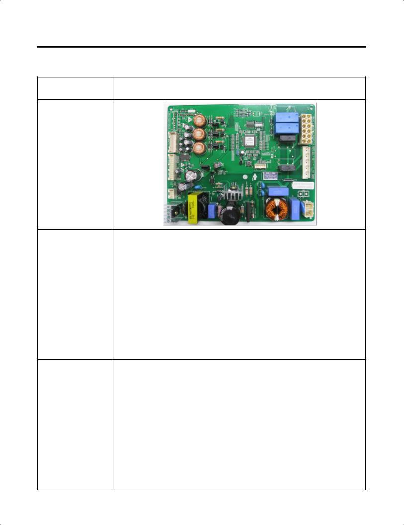
7. PCB Picture
7-1 Main PCB
P/No & MFG |
Picture |
|
CON4 |
|
|
|
|
CON3 |
|
|
|||||
|
|
|
|
|
|
|
EBR67348003 |
|
|
|
|
|
CON2 |
|
|
|
|
|
||
|
|
|
|
|
||
(2010.02~) |
CON5 |
|
|
|
|
|
|
|
|
|
|||
|
CON8 |
|
|
|
|
|
|
|
|
|
|
|
|
|
|
|
|
|
|
|
|
|
|
|
|
|
CON1 |
|
|
|
|
|
|
|
|
|
|
|
|
|
|
- 23 -
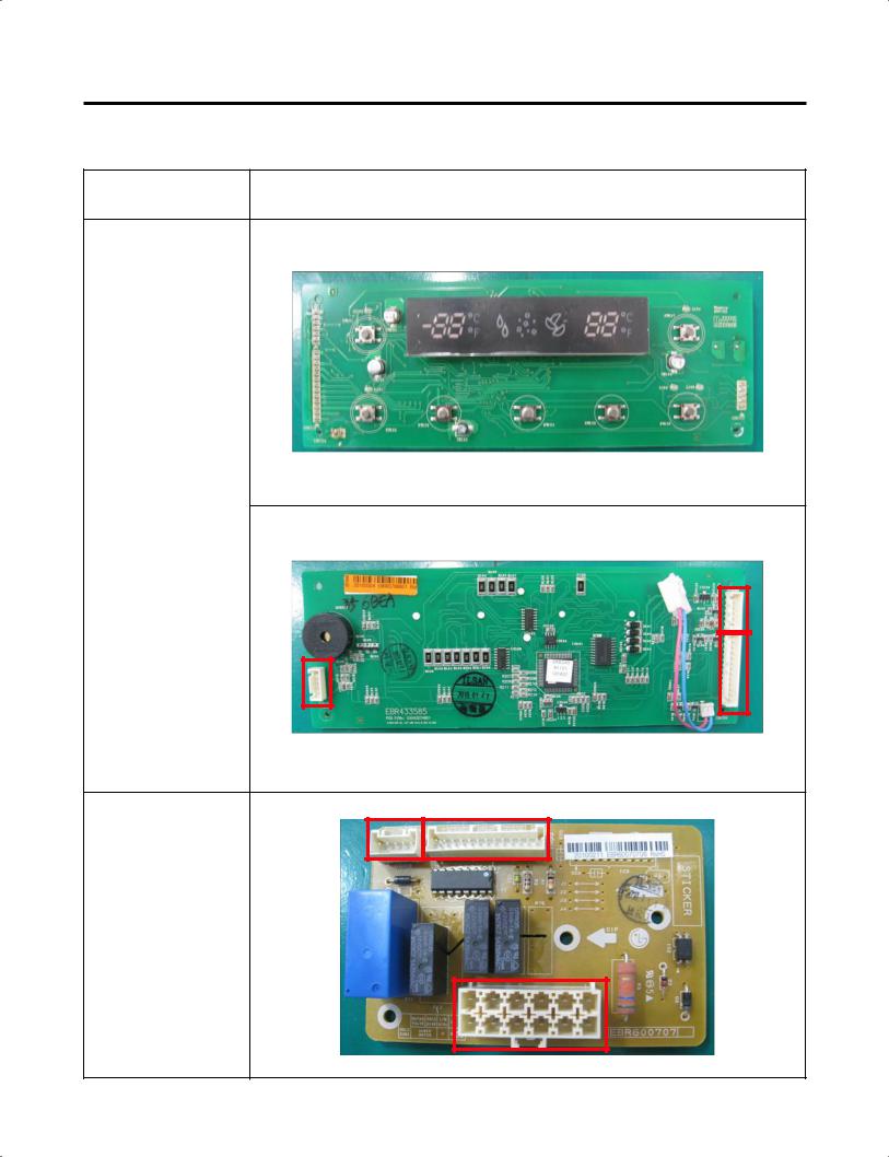
7-2 Display PCB & Sub PCB
P/No |
Picture |
Display PCB EBR43358505 (2010.02~)
CON101
CON102 |
CON104 |
|
CON3 CON1
Sub PCB
EBR60070706
(2010.02~)
CON2
- 24 -

8. Troubleshooting With Error Display
8-1 Freezer Sensor Error (Er FS)
No |
Checking flow |
|
|
|
Result & SVC Action |
|
||||||
|
|
|
|
|
|
|
|
|
|
|
|
|
1 |
Check for a loose connection. |
|
|
|
|
|
|
|
|
|
||
|
|
|
|
|
|
|
|
|
|
|
|
|
2 |
Check the Blue/White to |
|
|
|
|
|
|
|
|
|
||
|
|
Result |
SVC Action |
|
||||||||
|
Blue/White. |
|
|
|
|
|||||||
|
|
|
|
|
0 |
|
|
Short |
Change the sensor |
|
||
|
|
|
|
|
|
|
|
|
|
|
||
|
|
|
|
|
Infinite |
|
Open |
Replace the |
|
|||
|
|
|
|
|
ohms |
|
refrigerator |
|
||||
|
|
|
|
|
|
|
|
|||||
|
|
|
|
|
|
|
|
|
|
|
|
|
|
|
|
|
|
|
See |
|
|
Check the Temp and |
|
||
|
|
|
|
|
|
|
|
|
||||
|
|
|
|
|
resistance |
Normal |
|
|||||
|
|
|
|
|
resistance (Table-1) |
|
||||||
|
|
|
|
|
table |
|
|
|
||||
|
|
|
|
|
|
|
|
|
|
|||
|
|
|
|
|
|
|
|
|
|
|
|
|
|
|
<CON4> |
|
|
|
|
<Temperature table-1> |
|
||||
|
|
|
|
|
|
|
|
|
|
|||
|
|
|
|
|
|
|
(1) To (2) |
Result |
|
|
||
|
|
|
|
|
|
|
|
|
|
|
|
|
|
|
|
|
|
|
|
-22°F / -30°C |
40 |
|
|
||
|
|
|
|
|
|
|
|
|
|
|
||
|
|
|
|
|
|
|
-13°F / -25°C |
30 |
|
|
||
|
|
|
|
|
|
|
|
|
|
|
||
|
|
|
|
|
|
|
-4°F / -20°C |
23 |
|
|
||
|
|
|
|
|
|
|
|
|
|
|
||
|
|
|
|
|
|
|
5°F / -15°C |
17 |
|
|
||
|
|
|
|
|
|
|
|
|
|
|
||
|
|
|
|
|
|
|
14°F / -10°C |
13 |
|
|
||
|
|
|
|
|
|
|
|
|
|
|
||
|
|
|
|
|
|
|
23°F / -5°C |
10 |
|
|
||
|
|
|
|
|
|
|
|
|
|
|
||
|
|
|
|
|
|
|
32°F / 0°C |
8 |
|
|
||
|
|
|
|
|
|
|
|
|
|
|
||
|
|
|
|
|
The sensor is determined by |
|
||||||
|
|
|
|
|
the temperature. |
|
|
|
||||
|
|
|
|
|
For example, 23 |
indicates -4°F. |
|
|||||
|
|
|
|
|
|
|
|
|
|
|
|
|
- 25 -
 Loading...