


Ninja® 650R
ER-6f
ER-6f ABS
Motorcycle
Assembly & Preparation
Manual

Foreword
In order to ship Kawasaki vehicles as efficiently as possible, they are partially disassembled before crating. Since some of the most commonly removed parts have a direct bearing on a vehicle’s reliability and safety, conscientious pre-sale assembly and preparation becomes extremely important. Good setup procedures can prevent needless warranty claims and give customers a greater sense of confidence in Kawasaki and their Kawasaki Dealers.
This Assembly and Preparation Manual explains step by step procedures of the following items for the Kawasaki Ninja 650R, ER-6f and ER-6f ABS.
1.Uncrating
2.Assembly
3.Preparation
The selling dealer assumes sole responsibility for any unauthorized modifications prior to sale. Refer to your Service Binder for any Service Bulletins specifying Factory Directed Modifications (Special Claims) which must be performed before the vehicle is ready for sale.
Whenever you see the following symbols heed their instructions! Always follow safe operating and maintenance practices.
 WARNING
This warning symbol identifies special instructions or procedures which, if not correctly followed, could result in personal injury, or loss of life.
CAUTION
This caution symbol identifies special instructions or procedures which, if not correctly followed, could result in damage to, or destruction of equipment.
NOTE
This note symbol indicates points of particular interest for more efficient and convenient operation.
Kawasaki Heavy Industries, Ltd. accepts no liability for any inaccuracies or omissions in this publication, although every possible measure has been taken to make it as complete and accurate as possible. All procedures and specifications subject to change without notice.
© 2008 Kawasaki Heavy Industries, Ltd. |
Dec., 2008 |
Table of Contents |
|
Uncrating ...................................................................................... |
3 |
Opening Crate ............................................................................. |
3 |
Parts Check................................................................................. |
4 |
Assembly ...................................................................................... |
5 |
Handlebar.................................................................................... |
5 |
Throttle Grip and Right Switch Housing ...................................... |
5 |
Front Brake Master Cylinder ....................................................... |
6 |
Cables, Harness and Hoses Routing .......................................... |
7 |
Left Switch Housing..................................................................... |
8 |
Clutch Cable................................................................................ |
8 |
Lower Fairing............................................................................... |
8 |
Windshield................................................................................... |
9 |
Brake Disc Cleaning.................................................................... |
10 |
Preparation ................................................................................... |
10 |
Battery Service ............................................................................ |
10 |
Front Brake Fluid......................................................................... |
13 |
Rear Brake Fluid ......................................................................... |
14 |
Clutch Lever and Cable............................................................... |
16 |
Drive Chain.................................................................................. |
17 |
Rear Shock Absorber .................................................................. |
19 |
Tire Air Pressures........................................................................ |
19 |
Fuel ............................................................................................. |
19 |
Coolant ........................................................................................ |
20 |
Engine Oil (4-stroke) ................................................................... |
21 |
Idle Speed Adjustment ................................................................ |
22 |
Throttle Grip and Cable ............................................................... |
23 |
Rear Brake Light Switch.............................................................. |
24 |
Headlight Aim .............................................................................. |
24 |
Digital Meter ................................................................................ |
25 |
Fastener Check ........................................................................... |
26 |
Standard Torque Table ................................................................ |
28 |
Test Ride the Motorcycle ............................................................. |
28 |
A&P Check List ........................................................................... |
28 |
Uncrating
Opening Crate
 WARNING
Always wear protective gloves, boots and eye protection when uncrating to prevent injury.
 WARNING
Be careful not to injure your body by the sharp edges of the steel crate panel plates and other sharp fasteners.
•Clear a space about 6 m (20 ft) square to give yourself plenty of space to work.
•Place the crate upright on its base.
•Remove the cardboard cover.
•Remove the handlebar and the parts box.
CAUTION
When removing the crate bracket from the motorcycle, be careful not to drop any parts or the bracket onto the fuel tank and other components, and not to scratch the fuel tank or other components with the crate bracket.
UNCRATING 3
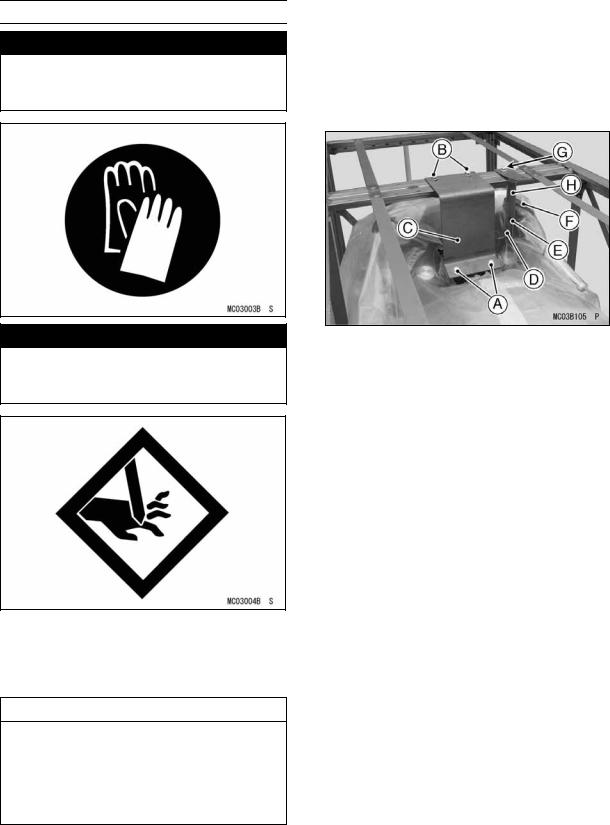
•First, remove the lower bolts (D = 8, L = 16) at the steering stem and discard them.
•Remove the upper bolts (D = 8, L = 22) to take off the steering stem support bracket and discard them.
•Remove the lower bolts (D = 6, L = 12) and washer to take off the front master cylinder.
•Remove the upper bolt (D = 8, L = 16) to take off the front master cylinder support bracket and discard it.
A.Lower Bolts (D = 8, L = 16)
B.Upper Bolts (D = 8, L = 22)
C.Steering Stem Support Bracket
D.Lower Bolt (D = 6, L = 12) and Washer
E.Lower Bolt (D = 6, L = 12)
F.Front Master Cylinder
G.Upper Bolt (D = 8, L = 16)
H.Front Master Cylinder Support Bracket
•Take out all the bolts and screws and remove the top and sides of the crate.
NOTE
Roll the vehicle off the crate base after installing the handlebar and front master cylinder.
4 UNCRATING
Parts Check
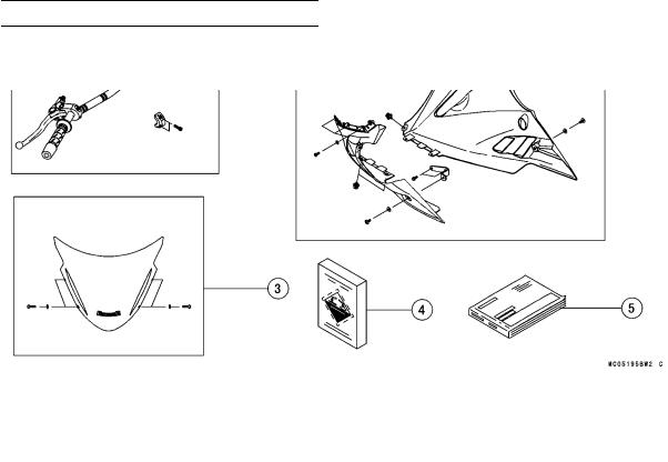
•Open the parts box, and check the parts against the illustrations. There may be minor differences between these illustrations and the actual vehicle parts. In the following charts under Remarks, D = diameter in millimeters, and L = length in millimeters.
|
|
|
|
|
|
|
|
|
|
|
|
No. |
Part Name |
Qty |
Remarks |
|
|
|
|
|
|
|
|
1 |
Handlebar with Grips, Weights and Clutch Lever Assy |
1 |
|
|
|
|
Clamp, Handlebar |
1 |
|
|
|
|
Socket Bolt, Clamp, Handlebar |
4 |
D = 8, L = 30 |
|
|
|
Clamp, Front Master Cylinder |
1 |
|
|
|
|
Socket Bolt, Clamp, Front Master Cylinder |
2 |
D = 6, L = 22 |
|
|
|
|
|
|
|
|
2 |
Left Bracket, Lower Fairing |
1 |
|
|
|
|
Flanged Bolt with Non-permanent Locking Agent, Left Bracket |
2 |
D = 6, L = 14 |
|
|
|
Lower Fairing, LH & RH |
2 |
|
|
|
|
|
|
|
||
|
Socket Bolt, Lower Fairing |
6 |
D = 5, L = 16 |
|
|
|
Plastic Washer, Lower Fairing |
6 |
D = 5.3 |
|
|
|
Socket Bolt, Lower Fairing |
|
D = 6, L = 14 |
|
|
|
2 |
|
|
||
|
Plastic Washer, Lower Fairing |
2 |
D = 6.5 |
|
|
|
Plastic Rivet, Lower Fairing |
3 |
|
|
|
|
|
|
|
|
|
3 |
Windshield |
1 |
|
|
|
|
Socket Bolt, Windshield |
4 |
D = 5, L = 20 |
|
|
|
Plastic Washer, Windshield |
4 |
D = 5.3 |
|
|
|
|
|
|
|
|
4 |
Battery Electrolyte, FTX12-BS |
1 |
12 V 10 Ah |
|
|
|
|
|
|
|
|
5 |
Owner’s Manual |
1 |
|
|
|
|
|
|
|
|
|
Assembly
Handlebar
Handlebar Installation
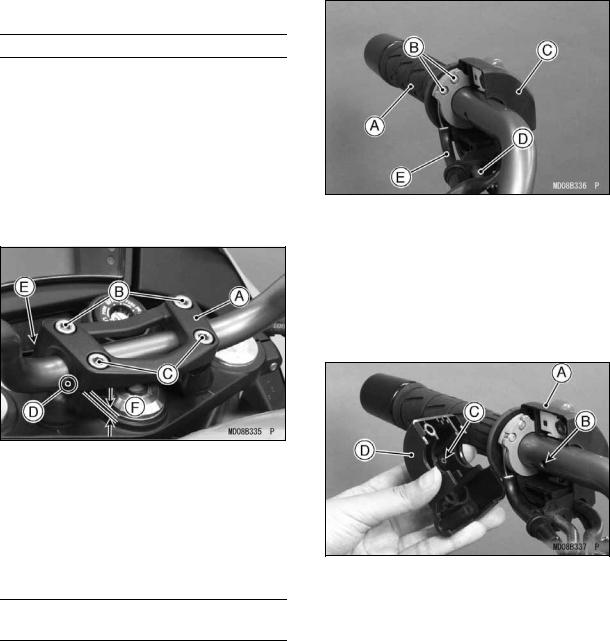
•Set the handlebar so that its punched mark is aligned with the upper rear edge of the lower handlebar clamp and install the upper handlebar clamp and bolts (D = 8, L = 30).
•Tighten the front clamp bolts first, and then the rear clamp bolts to the specified torque. There will be a gap at the rear part of the clamp after tightening.
Torque: 25 N·m (2.5 kgf·m, 18 ft·lb)
A.Handlebar Clamp (Upper)
B.Front Bolts (D = 8, L = 30)
C.Rear Bolts (D = 8, L = 30)
D.Punched Mark
E.No Gap
F.Gap
Throttle Grip and Right Switch
Housing
•Apply a light coat of grease on the exposed portion of the throttle inner cables.
•Fit both throttle cable tips into the nearest socket in the throttle grip.
ASSEMBLY 5
A.Throttle Grip
B.Cable Tips : Apply Grease.
C.Rear Half
D.Throttle Cable (Decelerator)
E.Throttle Cable (Accelerator)
•Fit the two halves of the right switch housing so that the projection on the front half fits into the hole in the handlebar.
A.Rear Half
B.Hole
C.Projection
D.Front Half
•Insert the two screws (D = 5, L = 25) (D = 5, L = 40) and tighten them.
6 ASSEMBLY
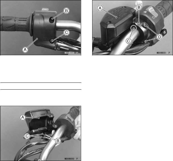
A.Right Switch Housing
B.Screw (D = 5, L = 25)
C.Screw (D = 5, L = 40)
Front Brake Master Cylinder
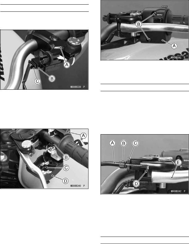
•Connect the right switch housing lead connectors to the front brake light switch terminals on the front brake master cylinder.
A.Front Master Cylinder
B.Brake Light Switch Terminals
C.Connectors and Dust Covers
•Install the front master cylinder with its clamp and the two bolts (D = 6, L = 22).
•Position the master cylinder so that the mating surface of the front and rear master cylinder clamps align with the punched mark on the handlebar.
A.Front Master Cylinder
B.Clamp
C.Punched Mark
D.Bolts (D = 6, L = 22)
•Tighten the upper clamp bolt first and then the lower clamp bolt to the specified torque.
Torque: 11 N·m (1.1 kgf·m, 97 in·lb)

ASSEMBLY 7
Cables, Harness and Hoses Routing
•Check that the cables, wiring leads and hoses are routed correctly.
Right Side View
Left Side View
A.Right Switch Housing Harness |
F.Left Switch Housing Harness |
B.Throttle Cable (Accelerator) |
G.Clutch Cable |
C.Throttle Cable (Decelerator) |
H.Run the clutch cable and left switch |
D.Front Brake Hose |
housing harness through the guide. |
E.From the inside sequentially, run the right switch |
I.Run the left switch housing harness |
housing harness, front brake hose, throttle ca- |
through the guide. |
ble (decelerator) and throttle cable (accelerator) |
|
through the guides. |
|
8 ASSEMBLY
Left Switch Housing
•Connect the left switch housing connector to the starter lock-out switch on the clutch lever assembly.
A.Clutch Lever Assy
B.Starter Lock-out Switch
C.Connector
•Fit the two halves of the left switch housing together so that the small projection on the front half fits into the hole in the handlebar.
A.Rear Half
B.Hole
C.Projection
D.Front Half
•Insert the two screws (D = 5, L = 25) and tighten them securely.
A.Left Switch Housing
B.Screws (D = 5, L = 25)
Clutch Cable
•Apply a light coat of grease on the clutch inner cable.
•Line up the slots on the clutch lever, locknut, and adjuster.
•Fit the tip of the clutch inner cable into the lever socket, slide the inner cable through the slots, and release the outer cable into the adjuster.
A.Clutch Cable
B.Adjuster
C.Locknut
D.Cable Tip
E.Clutch Lever
Lower Fairing
NOTE
It is recommended that the lower fairing should be installed after completing the steps in the “Coolant” section on page 20 in the PREPARATION chapter.
 Loading...