


KX125
KX250
Motorcycle
Service Manual

Quick Reference Guide
This quick reference guide will assist you in locating a desired topic or procedure.
•Bend the pages back to match the black tab of the desired chapter number with the black tab on the edge at each table of contents page.
•Refer to the sectional table of contents for the exact pages to locate the specific topic required.
General Information |
1 |
j |
|
|
|
Periodic Maintenance |
2 |
j |
|
|
|
Fuel System |
3 |
j |
|
|
|
Cooling System |
4 |
j |
|
|
|
Engine Top End |
5 |
j |
|
|
|
Engine Right Side |
6 |
j |
|
|
|
Engine Removal/Installation |
7 |
j |
|
|
|
Engine Bottom End/Transmission |
8 |
j |
|
|
|
Wheels/Tires |
9 |
j |
|
|
|
Final Drive |
10 |
j |
|
|
|
Brakes |
11 |
j |
|
|
|
Suspension |
12 |
j |
|
|
|
Steering |
13 |
j |
|
|
|
Electrical System |
14 |
j |
|
|
|
Appendix |
15 |
j |

KX125
KX250
Motorcycle
Service Manual
All rights reserved. No parts of this publication may be reproduced, stored in a retrieval system, or transmitted in any form or by any means, electronic mechanical photocopying, recording or otherwise, without the prior written permission of Quality Assurance Division/Consumer Products & Machinery Company/Kawasaki Heavy Industries, Ltd., Japan.
No liability can be accepted for any inaccuracies or omissions in this publication, although every possible care has been taken to make it as complete and accurate as possible.
The right is reserved to make changes at any time without prior notice and without incurring an obligation to make such changes to products manufactured previously. See your Motorcycle dealer for the latest information on product improvements incorporated after this publication.
All information contained in this publication is based on the latest product information available at the time of publication. Illustrations and photographs in this publication are intended for reference use only and may not depict actual model component parts.
© 2002 Kawasaki Heavy Industries, Ltd., |
7th Edition (1) : Mar. 22, 2007 (K) |
LIST OF ABBREVIATIONS
A |
ampere(s) |
lb |
pound(s) |
ABDC |
after bottom dead center |
m |
meter(s) |
AC |
alternating current |
min |
minute(s) |
ATDC |
after top dead center |
N |
newton(s) |
BBDC |
before bottom dead center |
Pa |
pascal(s) |
BDC |
bottom dead center |
PS |
horsepower |
BTDC |
before top dead center |
psi |
pound(s) per square inch |
°C |
degree(s) Celsius |
r |
revolution |
DC |
direct current |
rpm |
revolution(s) perminute |
F |
farad(s) |
TDC |
top dead center |
°F |
degree(s) Fahrenheit |
TIR |
total indicator reading |
ft |
foot, feet |
V |
volt(s) |
g |
gram(s) |
W |
watt(s) |
h |
hour(s) |
Ω |
ohm(s) |
L |
liter(s) |
|
|
Read OWNER’S MANUAL before operating

Foreword
This manual is designed primarily for use by trained mechanics in a properly equipped shop. However, it contains enough detail and basic information to make it useful to the owner who desires to perform his own basic maintenance and repair work. A basic knowledge of mechanics, the proper use of tools, and workshop procedures must be understood in order to carry out maintenance and repair satisfactorily. Whenever the owner has insufficient experience or doubts as to his ability to do the work, all adjustments, maintenance, and repair should be carried out only by qualified mechanics.
In order to perform the work efficiently and to avoid costly mistakes, read the text, thoroughly familiarize yourself with the procedures before starting work, and then do the work carefully in a clean area. Whenever special tools or equipment are specified, do not use makeshift tools or equipment. Precision measurements can only be made if the proper instruments are used, and the use of substitute tools may adversely affect safe operation.
To get the longest life out of your motorcycle:
•Follow the Periodic Maintenance Chart in the Service Manual.
•Be alert for problems and non-scheduled maintenance.
•Use proper tools and genuine Kawasaki motorcycle parts. Special tools, gauges, and testers that are necessary when servicing Kawasaki Motorcycles are introduced by the Service Manual. Genuine parts provided as spare parts are listed in the Parts Catalog.
•Follow the procedures in this manual carefully. Don’t take shortcuts.
•Remember to keep complete records of maintenance and repair with dates and any new parts installed.
How to Use this Manual
In this manual, the product is divided into its major systems and these systems make up the manual’s chapters. The Quick Reference Guide shows you all of the product’s system and assists in locating their chapters. Each chapter in turn has its own comprehensive Table of Contents.
For example, if you want ignition coil information, use the Quick Reference Guide to locate the Electrical System chapter. Then, use the Table of Contents on the first page of the chapter to find the Ignition Coil section.
Whenever you see these WARNING and CAUTION symbols, heed their instructions! Always follow safe operating and maintenance practices.

 WARNING
This warning symbol identifies special instructions or procedures which, if not correctly followed, could result in personal injury, or loss of life.
CAUTION
This caution symbol identifies special instructions or procedures which, if not strictly observed, could result in damage to or destruction of equipment.
This manual contains four more symbols (in addition to WARNING and CAUTION) which will help you distinguish different types of information.
NOTE
○This note symbol indicates points of particular interest for more efficient and convenient operation.
•Indicatesdone. a procedural step or work to be ○Indicates a procedural sub-step or how to do the work of the procedural step it follows. It
also precedes the text of a NOTE.
 Indicates a conditional step or what action to take based on the results of the test or inspection in the procedural step or sub-step it follows.
In most chapters an exploded view illustration of the system components follows the Table of Contents. In these illustrations you will find the instructions indicating which parts require specified tightening torque, oil, grease or a locking agent during assembly.

GENERAL INFORMATION 1-1
General Information |
|
|
|
|
1 |
|
|
Table of Contents |
|
|
|
Before Servicing ..................................................................................................................... |
1-2 |
|
|
Model Identification................................................................................................................. |
1-5 |
|
|
General Specifications............................................................................................................ |
1-7 |
|
|
Technical Information.............................................................................................................. |
1-13 |
|
|
Unit Conversion Table ............................................................................................................ |
1-21 |
|
|

1-2 GENERAL INFORMATION
Before Servicing
Before starting to perform an inspection service or carry out a disassembly and reassembly operation on a motorcycle, read the precautions given below. To facilitate actual operations, notes, illustrations, photographs, cautions, and detailed descriptions have been included in each chapter wherever necessary. This section explains the items that require particular attention during the removal and reinstallation or disassembly and reassembly of general parts.
Especially note the following:
(1) Dirt
Before removal and disassembly, clean the motorcycle. Any dirt entering the engine will shorten the life of the motorcycle. For the same reason, before installing a new part, clean off any dust or metal filings.
(2) Battery Ground
Disconnect the ground (–) cable from the battery before performing any disassembly operations on the motorcycle. This prevents the engine from accidentally turning over while work is being carried out, sparks from being generated while disconnecting the leads from electrical parts, as well as damage to the electrical parts themselves. For reinstallation, first connect the positive cable to the positive (+) terminal of the battery
(3) Installation, Assembly
Generally, installation or assembly is the reverse of removal or disassembly. However, if installation or assembly sequence is given in this Service Manual, follow it. Note parts locations and cable, wire, and hose routing during removal or disassembly so they can be installed or assembled in the same way. It is preferable to mark and record the locations and routing whenever possible.
(4) Tightening Sequence
When installing bolts, nuts, or screws for which a tightening sequence is given in this Service Manual, make sure to follow the sequence. When installing a part with several bolts, nuts, or screws, start them all in their holes and tighten them to a snug fit, thus ensuring that the part has been installed in its proper location. Then, tighten them to the specified torque in the tightening sequence and method indicated. If tightening sequence instructions are not given, tighten them evenly in a cross pattern. Conversely, to remove a part, first loosen all the bolts, nuts, or screws that are retaining the part a 1/4-turn before removing them.
(5) Torque
When torque values are given in this Service Manual, use them. Either too little or too much torque may lead to serious damage. Use a good quality, reliable torque wrench.
(6) Force
Common sense should dictate how much force is necessary in assembly and disassembly. If a part seems especially difficult to remove or install, stop and examine what may be causing the problem. Whenever tapping is necessary, tap lightly using a wooden or plastic-faced mallet. Use an impact driver for screws (particularly for the removing screws held by non-permanent locking agent) in order to avoid damaging the screw heads.
(7) Edges
Watch for sharp edges, as they could cause injury through careless handling, especially during major engine disassembly and assembly. Use a clean piece of thick cloth when lifting the engine or turning it over.
(8) High-Flash Point Solvent
A high-flash point solvent is recommended to reduce fire danger. A commercial solvent commonly available in North America is standard solvent (generic name). Always follow manufacturer and container directions regarding the use of any solvent.
(9) Gasket, O-ring
Replace a gasket or an O-ring with a new part when disassembling. Remove any foreign matter from the mating surface of the gasket or O-ring to ensure a perfectly smooth surface to prevent oil or compression leaks.
(10)Liquid Gasket, Locking Agent
Clean and prepare surfaces where liquid gasket or non-permanent locking agent will be used. Apply them sparingly. Excessive amount may block engine oil passages and cause serious damage.
GENERAL INFORMATION 1-3
Before Servicing
(11)Press
When using a press or driver to install a part such as a wheel bearing, apply a small amount of oil to the area where the two parts come in contact to ensure a smooth fit.
(12)Ball Bearing and Needle Bearing
Do not remove a ball bearing or a needle bearing unless it is absolutely necessary. Replace any ball or needle bearings that were removed with new ones. Install bearings with the manufacturer and size marks facing out, applying pressure evenly with a suitable driver. Apply force only to the end of the race that contacts the press fit portion, and press it evenly over the base component.
(13)Oil Seal and Grease Seal
Replace any oil or grease seals that were removed with new ones, as removal generally damages seals. Oil or grease seals should be pressed into place using a suitable driver, applying a force uniformly to the end of seal until the face of the seal is even with the end of the hole, unless instructed otherwise. When pressing in an oil or grease seal which has manufacturer’s marks, press it in with the marks facing out.
(14)Circlip, Retaining Ring, and Cotter Pin
When installing circlips and retaining rings, take care to compress or expand them only enough to install them and no more. Install the circlip with its chamfered side facing load side as well.
Replace any circlips, retaining rings, and cotter pins that were removed with new ones, as removal weakens and deforms them. If old ones are reused, they could become detached while the motorcycle is driven, leading to a major problem.
(15)Lubrication
Engine wear is generally at its maximum while the engine is warming up and before all the sliding surfaces have an adequate lubricative film. During assembly, make sure to apply oil to any sliding surface or bearing that has been cleaned. Old grease or dirty oil could have lost its lubricative quality and may contain foreign particles that act as abrasives; therefore, make sure to wipe it off and apply fresh grease or oil. Some oils and greases in particular should be used only in certain applications and may be harmful if used in an application for which they are not intended.
(16)Direction of Engine Rotation
To rotate the crankshaft manually, make sure to do so in the direction of positive rotation. Positive rotation is counterclockwise as viewed from the left side of the engine. To carry out proper adjustment, it is furthermore necessary to rotate the engine in the direction of positive rotation as well.
(17)Replacement Parts
When there is a replacement instruction, replace these parts with new ones every time they are removed.
Replacement parts will be damaged or lose their original function once they are removed. Therefore, always replace these parts with new ones every time they are removed. Although the previously mentioned gasket, O-ring, ball bearing, needle bearing, grease seal, oil seal, circlip, and cotter pin have not been so designated in their respective text, they are replacement parts.
(18)Electrical Leads
All the electrical leads are either one-color or two-color. A two-color lead is identified first by the primary color and then the stripe color. For example, a yellow lead with thin red stripes is referred to as a “yellow/red” lead; it would be a “red/yellow” lead if the colors were reversed. Unless instructed otherwise, electrical leads must be connected to leads of the same color.
Two-Color Electrical

1-4 GENERAL INFORMATION
Before Servicing
(19)Inspection
When parts have been disassembled, visually inspect these parts for the following conditions or other damage. If there is any doubt as to the condition of them, replace them with new ones.
Abrasion |
Crack |
Hardening |
Warp |
Bent |
Dent |
Scratch |
Wear |
Color change |
Deterioration |
Seizure |
|
(20)Specifications
Specification terms are defined as follows:
“Standards” show dimensions or performances which brand-new parts or systems have. “Service Limits” indicate the usable limits. If the measurement shows excessive wear or deteri-
orated performance, replace the damaged parts.
GENERAL INFORMATION 1-5
Model Identification
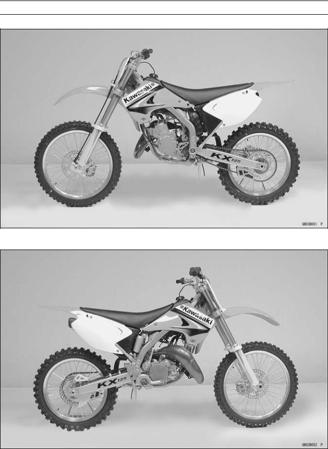
KX125-M1 Left Side View
KX125-M1 Right Side View

1-6 GENERAL INFORMATION
Model Identification
KX250-M1 Left Side View
KX250-M1 Right Side View

GENERAL INFORMATION 1-7
General Specifications
Items |
KX125-M1 |
KX125-M2 M3 |
|
KX125M6F |
Dimensions |
|
|
|
|
Overall Length |
2 155 mm (84.8 in.) |
2 165 mm (85.2 in.) |
||
Overall Width |
825 mm (32.5 in.) |
840 mm (33.1 in.) |
|
815 mm (32.1 in.) |
Overall Height |
1 200 mm (47.2 in.) |
1 265 mm (49.8 in.) |
||
Wheelbase |
1 455 mm (57.3 in.) |
1 470 mm (57.9 in.) |
||
Road Clearance |
340 mm (13.4 in.) |
|
← |
|
Seat Height |
930 mm (36.6 in.) |
940 mm (37.0 in.) |
||
Dry Mass |
87 kg (192 lb) |
|
← |
|
Curb Mass: |
|
|
|
|
Front |
45 kg (99 lb) |
|
← |
|
Rear |
47 kg (104 lb) |
|
← |
|
Fuel Tank Capacity |
8.2 L (2.2 US gal) |
|
← |
|
Engine |
|
|
|
|
Type |
2-stroke, single cylinder, |
|
← |
|
|
crankcase reed valve |
|
||
|
|
|
|
|
Cooling System |
Liquid-cooled |
|
← |
|
Bore and Stroke |
54.0 × 54.5 mm (2.13 × 2.15 in.) |
|
← |
|
Displacement |
124 cm³(7.6 cu in.) |
|
← |
|
Compression Ratio: |
|
|
|
|
Low Speed |
10.6 : 1 |
11.1 : 1 (EUR) 10.9 : 1 |
||
High Speed |
8.1 : 1 |
8.5 : 1 (EUR) 8.3 : 1 |
||
Carburetion System |
Carburetor, MIKUNI TMX38χ |
|
← |
|
Starting System |
Primary kick |
|
← |
|
Ignition System |
CDI |
|
← |
|
Ignition Timing |
13° BTDC @9 710 r/min (rpm) |
13° BTDC @9 710 r/min (rpm) |
||
Spark Plug |
NGK BR9EIX |
NGK R6918B-9 |
|
NGK BR9ECMVX |
Port Timing |
|
|
|
|
Inlet: |
|
|
|
|
Open |
Full open |
|
← |
|
Close |
– |
|
|
– |
Scavenging: |
|
|
|
|
Open |
64.9° BBDC |
|
← |
|
Close |
64.9° ABDC |
|
← |
|
Exhaust: |
|
|
|
|
Open |
73.8° BBDC (low speed), |
|
← |
|
|
95.4° BBDC (high speed) |
|
← |
|
Close |
73.8° ABDC (low speed), |
|
← |
|
|
95.4° ABDC (high speed) |
|
← |
|
Lubrication System |
Petrol mix (32 : 1) |
|
← |
|
(Gasoline : Oil) |
|
|
|
|
Drive Train |
|
|
|
|
Primary Reduction |
|
|
|
|
System: |
|
|
|
|
Type |
Gear |
|
← |
|
Reduction Ratio |
3.200 (64/20) |
|
← |
|

1-8 GENERAL INFORMATION
General Specifications
Items |
KX125-M1 |
KX125-M2 |
M3 |
KX125M6F |
Clutch Type |
Wet, multi disc |
|
← |
|
Transmission: |
|
|
|
|
Type |
6-speed, constant mesh, return |
|
← |
|
|
shift |
|
|
|
Gear Ratios: |
|
|
|
|
1st |
2.384 (31/13) |
|
← |
|
2nd |
1.857 (26/14) |
|
← |
|
3rd |
1.529 (26/17) |
|
← |
|
4th |
1.294 (22/17) |
|
← |
|
5th |
1.125 (27/24) |
|
← |
|
6th |
1.000 (25/25) |
|
← |
|
Final Drive System: |
|
|
|
|
Type |
Chain drive |
|
← |
|
Reduction Ratio |
3.923 (51/13) |
|
← |
|
Overall Drive Ratio |
12.553 @Top gear |
|
← |
|
Transmission Oil: |
|
|
|
|
Grade |
API SE, SF or SG |
← |
|
API SH, SJ or |
|
API SH or SJ with JASO MA |
|
SL with JASOMA |
|
|
|
|
(KX125M7F ) |
|
|
|
|
|
|
Viscosity |
SAE 10W-40 |
|
← |
|
Capacity |
0.7 L (0.74 US qt) |
|
← |
|
Frame |
|
|
|
|
Type |
Tubular, semi-double cradle |
|
← |
|
Steering Angle |
45° to either side |
42° to either side |
||
Caster (rake angle) |
27.5° |
|
27° |
|
Trail |
100 mm (3.9 in.) |
113 mm (4.4 in.) |
||
Front Tire: |
|
|
|
|
Size |
80/100-21 51M |
|
← |
|
Make/Type |
DUNLOP, Tube type |
|
← |
|
Rear Tire: |
|
|
|
|
Size |
100/90-19 57M |
|
← |
|
Make/Type |
DUNLOP, Tube type |
|
← |
|
Rim Size: |
|
|
|
|
Front |
21 × 1.60 |
|
← |
|
Rear |
19 × 1.85 |
|
← |
|
Front Suspension: |
|
|
|
|
Type |
Telescopic fork (up side down) |
|
← |
|
Wheel Travel |
300 mm (11.8 in.) |
|
← |
|
Rear Suspension: |
|
|
|
|
Type |
Swingarm (Uni-trak) |
Swingarm (New Uni-trak) |
||
Wheel Travel |
310 mm (12.2 in.) |
|
← |
|
Brake Type: |
|
|
|
|
Front and Rear |
Single disc |
|
← |
|
|
|
|
|
|

GENERAL INFORMATION 1-9
General Specifications
Items |
KX125-M1 |
KX125-M2 |
M3 |
KX125M6F |
|
Effective Disc Diameter: |
|
|
|
|
|
Front |
220 mm (8.7 in.) |
225 |
mm (8.9 |
in.) |
|
Rear |
200 mm (7.9 in.) |
215 |
mm (8.5 |
in.) |
|
Specifications are subject to change without notice, and may not apply to every country. (EUR): Europe Model

1-10 GENERAL INFORMATION
General Specifications
Items |
KX250-M1 |
KX250-M2 |
|
Dimensions |
|
|
|
Overall Length |
2 175 mm (85.6 in.) |
← |
|
Overall Width |
825 mm (32.5 in.) |
840 mm (33.1 in.) |
|
Overall Height |
1 205 mm (47.4 in.) |
1 265 mm (49.8 in.) |
|
Wheelbase |
1 480 mm (58.3 in.) |
← |
|
Road Clearance |
355 mm (14.0 in.) |
340 mm (13.4 in.) |
|
Seat Height |
945 mm (37.2 in.) |
← |
|
Dry Mass |
97 kg (214 lb) |
← |
|
Curb Mass: |
|
|
|
Front |
50 kg (110 lb) |
← |
|
Rear |
51 kg (112 lb) |
← |
|
Fuel tank Capacity |
8.2 L (2.2 US gal) |
← |
|
Engine |
|
|
|
Type |
2-stroke, single cylinder, piston |
← |
|
|
reed valve |
|
|
|
|
|
|
Cooling System |
Liquid-cooled |
← |
|
Bore and Stroke |
66.4 × 72.0 mm (2.61 × 2.85 in.) |
← |
|
Displacement |
249 cm³ (15.25 cu in.) |
← |
|
Compression Ratio |
|
|
|
Low Speed |
10.1 : 1 |
10.5 : |
1 |
High Speed |
8.6 : 1 |
8.8 : |
1 |
Carburetion System |
Carburetor, KEIHIN PWK38S |
← |
|
Starting System |
Primary kick |
← |
|
Ignition System |
CDI |
← |
|
Ignition Timing |
14° BTDC @7 740 r/min (rpm) |
← |
|
Spark Plug |
NGK BR8EIX |
← |
|
Port Timing: |
|
|
|
Inlet: |
|
|
|
Open |
Full open |
← |
|
Close |
– |
– |
|
Scavenging: |
|
|
|
Open |
57.6° BBDC |
59.3° BBDC |
|
Close |
57.6° ABDC |
59.3° ABDC |
|
Exhaust: |
|
|
|
Open |
78.1° BBDC (low speed), |
78.4° BBDC (low speed), |
|
|
91.4° BBDC (high speed) |
92.2° BBDC (high speed) |
|
Close |
78.1° ABDC (low speed), |
78.4° ABDC (low speed), |
|
|
91.4° ABDC (high speed) |
92.2° ABDC (high speed) |
|
Lubrication System (Gasoline: Oil) |
Petrol mix (32 : 1) |
← |
|
Drive Train |
|
|
|
Primary Reduction System: |
|
|
|
Type |
Gear |
← |
|
Reduction ratio |
3.000 (63/21) |
← |
|
Clutch Type |
Wet, multi disc |
← |
|

GENERAL INFORMATION 1-11
General Specifications
Items |
KX250-M1 |
KX250-M2 |
|
Transmission: |
|
|
|
Type |
5 speed, constant mesh, return |
← |
|
|
shift |
|
|
Gear Ratios: |
|
|
|
1st |
1.800 (27/15) |
← |
|
2nd |
1.437 (23/16) |
← |
|
3rd |
1.176 (20/17) |
← |
|
4th |
1.000 (21/21) |
← |
|
5th |
0.869 (20/23) |
← |
|
Final Drive System |
|
|
|
Type |
Chain drive |
← |
|
Reduction Ratio |
3.769 (49/13) |
← |
|
Overall Drive Ratio |
9.832 @Top gear |
← |
|
Transmission Oil: |
|
|
|
Grade |
API SE, SF or SG |
← |
|
|
API SH or SJ with JASO MA |
← |
|
Viscosity |
SAE 10W-40 |
← |
|
Capacity |
0.85 L (0.90 US qt) |
← |
|
Frame |
|
|
|
Type |
Tubular, semi-double cradle |
← |
|
Steering Angle |
45° to either side |
42° to either side |
|
Caster (rake angle) |
27° |
← |
|
Trail |
97 mm (3.8 in.) |
112 mm (4.4 in.) |
|
Front Tire: |
|
|
|
Size |
80/100-21 51M |
← |
|
Make/Type |
BRIDGESTONE, Tube type |
← |
|
|
(EUR) DUNLOP, Tube type |
← |
|
Rear Tire: |
|
|
|
Size |
110/90-19 62M |
← |
|
Make/Type |
BRIDGESTONE, Tube type |
← |
|
|
(EUR) DUNLOP, Tube type |
← |
|
Rim Size: |
|
|
|
Front |
21 × 1.60 |
← |
|
Rear |
19 × 2.15 |
← |
|
Front Suspension: |
|
|
|
Type |
Telescopic fork (up side down) |
← |
|
Wheel Travel |
300 mm (11.8 in.) |
← |
|
Rear Suspension: |
|
|
|
Type |
Swingarm (Uni-trak) |
Swingarm (New Uni-trak) |
|
Wheel Travel |
310 mm (12.2 in.) |
← |
|
Brake Type: |
|
|
|
Front and Rear |
Single disc |
← |
|
|
|
|

1-12 GENERAL INFORMATION
General Specifications
Items |
KX250-M1 |
KX250-M2 |
Effective Disc Diameter: |
|
|
Front |
220 mm (8.7 in.) |
225 mm (8.9 in.) |
Rear |
200 mm (7.9 in.) |
215 mm (8.5 in.) |
Specifications are subject to change without notice, and may not apply to every country. (EUR): Europe Model
GENERAL INFORMATION 1-13
Technical Information
Ratchet-Type Shift Mechanism (KX250M, KX125M)
○The shift mechanism of the KX250M (5-speed) is shown in the following figure.
○This mechanism is stronger and simpler than the usual slide type and enables light and positive shifting. When the shift pedal [D] is applied, its turning force is transmitted almost directly to the shift drum [E].
○The mechanism has shorter length between the shift drum and the drive shaft, compared with the previous model (for example, from 67 mm to 43.2 mm for KX125).
○The shift force is transmitted as follows:
Shift Pedal → Shift Shaft [F] → Shift Mechanism Arm [G] → Ratchet [H] → Pawls [I], [M] in Ratchet → Shift Drum Cam [J] → Shift Forks → Gears
|
|
|
|
|
|
A. Top View |
F. Top View |
K. Gear Set Lever |
B. Front |
G. Shift Mechanism Arm |
L. Return Spring Pin |
C. Ratchet Plate |
H. Ratchet |
M. Lower Pawl |
D. Shift Pedal |
I. Upper Pawls |
N. Neutral Detent |
E. Shift Drum |
J. Shift Drum Cam |
O. Return Spring |

1-14 GENERAL INFORMATION
Technical Information
○This mechanism operates as follows:
1.Suppose the 1st gear position is set as shown. Neutral Detent [N]
2.Shift Up (for example: shift from 1st to 2nd) (→) : transmitting of shift force
The shift pedal is lifted. → The arm [G] turns counterclockwise until it stops at pin [L]. → ratchet [H] → lower pawl [M] → shift drum cam [J] → shift drum → The gear is shifted in 2nd position.
3.Ratchet Returns.
The arm [G] returns by force of spring [O]. →The ratchet
[H]disengages to be free by itself. → The set lever [K] holds the shift drum cam [J]. → The ratchet [H] returns (turns clockwise).
4.The 2nd Gear Position settles.
The upper and lower pawls [I], [M] catch the next teeth inside the shift drum cam [J] → The ratchet [H] settles in position. → The 2nd gear position settles.
5.Shift Down (for example: shift from 2nd to 1st)
The shift pedal is depressed. →The arm [G] turns clockwise until it stops at the pin [L]. → ratchet [H] → upper pawl [I] → shift drum cam [J] → shift drum → The gear is shifted into 1st position. → (continues to operate in the same way as Shift Up)
GENERAL INFORMATION 1-15
Technical Information
Chrome Composite Plating Cylinder (KX250M, KX125M)
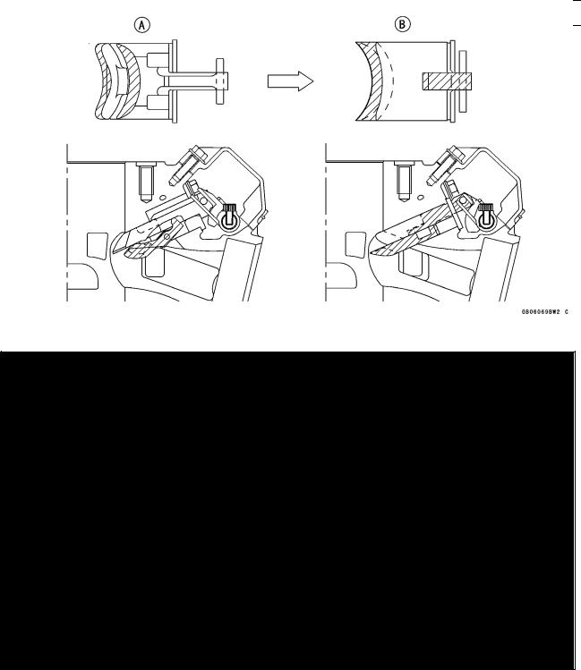
○This new cylinder bore [A] has Kawasaki’s composite cylinder plating, which is used for the first time on two stroke engines. The composite plating includes a nickel-phosphorous alloy, inorganic materials like ceramic, silicone carbide and some organic materials.
○The treatment improves heat transfer of the cylinder for consistent power output, allows closer piston-to-cylinder clearances for more horsepower.
○The treatment is porous, so it holds lubrication well, and hard, so it resists abrasion and seizure.
○This plating gets on well even the chamfered edge of the cylinder top or port.
○This improves the surface of the chamber at the top of the cylinder, preventing hot spots, resultant pre-ignition and other abnormal combustion in the chamber.
Previous Cylinder [A] New Cylinder [B] Exhaust Port [C] Cylinder Top [D]
○This enables the top end of the exhaust port from round to straight in order to make gas flow smooth and improve mid-high performance and extending piston ring life.
Previous Cylinder [A] New Cylinder [B] Exhaust Port [C]
1-16 GENERAL INFORMATION
Technical Information
KIPS (Kawasaki Integrated Power Valve System, KX250M, KX125M)
○KIPS varies the exhaust port height to broaden the useful rpm range for low end and mid-range without sacrificing the top end power (see ’95 KDX200H Service Manual (Part No. 99924-1181-01) for basic information about KIPS).
○KIPS is 2-stage-3-way type: the main exhaust port is opened earlier than the sub-exhaust ports (2-stage) and they are opened differently in low, middle and high rpm (3-way).
(In low rpm)
resonator: open to fully, sub-exhaust ports and main exhaust port: close (In middle rpm)
resonator: close, main exhaust port: open to fully, sub-exhaust ports open to halfway (In high rpm)
resonator: close, main exhaust port and sub-exhaust ports open fully. ○The KIPS valve is now made of aluminum instead of steel to save weight.
○The KIPS main valve holder shape is modified to match the straightened exhaust port, and timing for the main and sub-valves is changed to deliver more power in the low to mid-range.
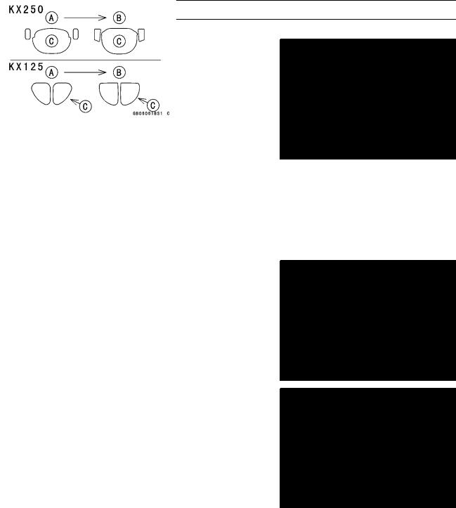
○The main valve end is changed from thick end to thin end, reducing exhaust pressure on the valve and making valve operation smooth.
(KX250M)
A.Previous KIPS
B.New KIPS
GENERAL INFORMATION 1-17
Technical Information
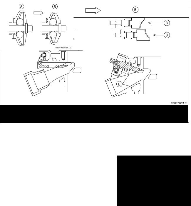
(KX125M)
A.Previous KIPS
B.New Model
C.Full Opened Position
D.Low Speed Position
E.Straightened Exhaust Passage
○The KIPS governor is modified so that the exhaust valves operate over a wider rpm range to improve low and mid -range power and smooth the power delivery.
○The KX250’s governor inside is changed from straight to concave in order to move the balls smoothly.
Previous Governor [A] New Governor [B]
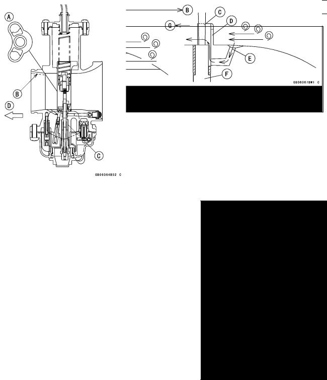
Carburetor (KX250M)
○The 38.7 mm (1.524 in.) Keihin PWK 38S carburetor helps boost mid-range and top-end power.
1-18 GENERAL INFORMATION
Technical Information
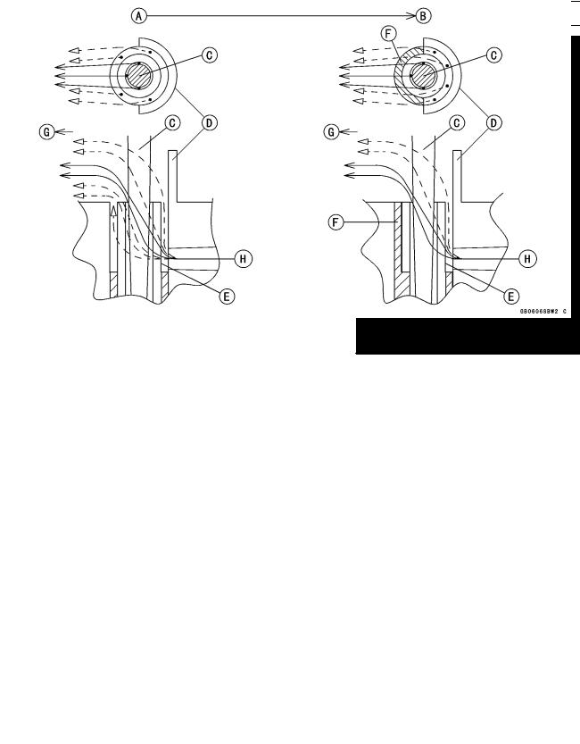
○The crescent shaped slide [A] enables the needle to sit closer to the intake ports for quicker throttle response.
○Large bores in the front and back of the carburetor and a smoother shape (38 to 40 mm-tapered bore [B]) boost mixture flow for more mid-range and top-end power.
○The semi air bleed needle jet [C] improves throttle response in the very low and low range.
Front [D]
○The air baffle forms vacuum, the stop narrows the outlet and speeds up outflow from the needle jet, improving atomization.
|
|
|
|
←—: |
Fuel Droplets |
|
|
← - -: |
Fuel Mist |
|
|
A. Previous Carburetor |
E. Needle Jet |
|
|
B. New Carburetor |
F. Stop |
|
|
C. Jet Needle |
G. Engine Inlet |
|
|
D. Air Baffle |
H. Main Air |
|
|
○The new main air inlet tends to take in static pressure and to exclude dynamic pressure and vortexes, making the main air flow stable.
GENERAL INFORMATION 1-19
Technical Information
A.Previous Carburetor
B.New Carburetor
C.Jet Needle
D.Air Baffle
E.Main Air
F.Needle Jet
G.Engine Inlet
Carburetor (KX125M)
○The 38 mm (1.496 in.) Mikuni TMX 38-27 carburetor helps boost mid-range and top-end power.
○The arched slide [A] improves throttle response in the very low and low ranges.
○Large bores in the front and back of the carburetor and a smoother shape (38 to 40 mm-tapered bore [B]) boost mixture flow for more mid-range and top-end power.
○The semi air bleed needle jet [C] improves throttle response in the low range and provides proper mixture from the low to top range.
Front [D]
1-20 GENERAL INFORMATION
Technical Information
○In low range, fuel drops in the fuel/air mixture is larger and tends to stick to the carburetor wall. The arched slide deflects fuel/air mixture flow from the wall to the middle of the carburetor for better atomization and better throttle response.
A.Previous Carburetor
B.New Carburetor
C.Flat Slide (piston valve)
D.Arched Shape Slide (piston valve)
E.Engine Intake
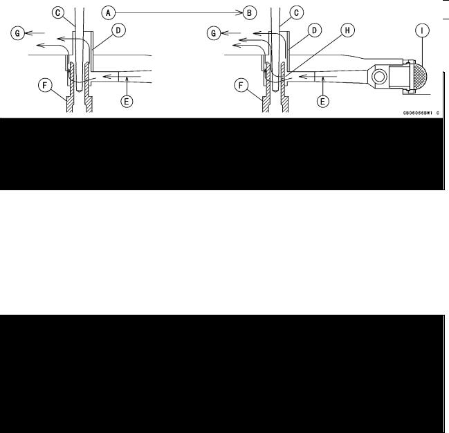
○The semi air bleed hole is positioned at the side of the needle jet, where fuel mixes with air well (due to enough fuel and faster air flow than in main bore), resulting in better atomizing. The air screen suppresses dynamic pressure around the main air inlet.
A.Previous Carburetor
B.New Carburetor
C.Jet Needle
D.Air Baffle
E.Main Air
F.Needle Jet
G.Engine Intake
H.Semi Air Bleed Hole
I.Air Screen

GENERAL INFORMATION 1-21
Unit Conversion Table
Prefixes for Units: |
Units of Length: |
Prefix |
Symbol |
|
Power |
|
mega |
M |
× 1 000 |
000 |
|
kilo |
k |
× |
1 000 |
|
centi |
c |
× |
0.01 |
|
milli |
m |
× |
0.001 |
|
micro |
µ |
× 0.000001 |
||
Units of Mass:
kg |
× |
2.205 |
= |
lb |
g |
× |
0.03527 |
= |
oz |
Units of Volume:
L |
× |
0.2642 |
= |
gal (US) |
L |
× |
0.2200 |
= |
gal (imp) |
L |
× |
1.057 |
= |
qt (US) |
L |
× |
0.8799 |
= |
qt (imp) |
L |
× |
2.113 |
= |
pint (US) |
L |
× |
1.816 |
= |
pint (imp) |
mL |
× |
0.03381 |
= |
oz (US) |
mL |
× |
0.02816 |
= |
oz (imp) |
mL |
× |
0.06102 |
= |
cu in |
Units of Force:
N |
× |
0.1020 |
= |
kgf |
N |
× |
0.2248 |
= |
lb |
kgf |
× |
9.807 |
= |
N |
kgf |
× |
2.205 |
= |
lb |
km |
× |
0.6214 |
= |
mile |
m |
× |
3.281 |
= |
ft |
mm |
× |
0.03937 |
= |
in |
Units of Torque:
N·m |
× |
0.1020 |
= |
kgf·m |
N·m |
× |
0.7376 |
= |
ft·lb |
N·m |
× |
8.851 |
= |
in·lb |
kgf·m |
× |
9.807 |
= |
N·m |
kgf·m |
× |
7.233 |
= |
ft·lb |
kgf·m |
× |
86.80 |
= |
in·lb |
Units of Pressure:
kPa |
× |
0.01020 |
= |
kgf/cm² |
kPa |
× |
0.1450 |
= |
psi |
kPa |
× |
0.7501 |
= |
cm Hg |
kgf/cm² |
× |
98.07 |
= |
kPa |
kgf/cm² |
× |
14.22 |
= |
psi |
cm Hg |
× |
1.333 |
= |
kPa |
Units of Speed:
km/h × 0.6214 = mph
Units of Power:
kW |
× |
1.360 |
= |
PS |
kW |
× |
1.341 |
= |
HP |
PS |
× |
0.7355 |
= |
kW |
PS |
× |
0.9863 |
= |
HP |
Units of Temperature:
 Loading...