


 Loading...
KX65
Motorcycle
Service Manual

Quick Reference Guide
General Information |
1 |
j |
|
|
|
Fuel System |
2 |
j |
|
|
|
Cooling System |
3 |
j |
|
|
|
Engine Top End |
4 |
j |
|
|
|
Engine Right Side |
5 |
j |
|
|
|
Engine Removal/Installation |
6 |
j |
|
|
|
Engine Bottom End/Transmission |
7 |
j |
|
|
|
Wheels/Tires |
8 |
j |
|
|
|
Final Drive |
9 |
j |
|
|
|
Brakes |
10 |
j |
|
|
|
Suspension |
11 |
j |
|
|
|
Steering |
12 |
j |
|
|
|
Electrical System |
13 |
j |
|
|
|
Appendix |
14 |
j |
This quick reference guide will assist you in locating a desired topic or procedure.
•Bend the pages back to match the black tab of the desired chapter number with the black tab on the edge at each table of contents page.
•Refer to the sectional table of contents for the exact pages to locate the specific topic required.

KX65
Motorcycle
Service Manual
All rights reserved. No parts of this publication may be reproduced, stored in a retrieval system, or transmitted in any form or by any means, electronic mechanical photocopying, recording or otherwise, without the prior written permission of Quality Assurance Division/Consumer Products & Machinery Company/Kawasaki Heavy Industries, Ltd., Japan.
No liability can be accepted for any inaccuracies or omissions in this publication, although every possible care has been taken to make it as complete and accurate as possible.
The right is reserved to make changes at any time without prior notice and without incurring an obligation to make such changes to products manufactured previously. See your Motorcycle dealer for the latest information on product improvements incorporated after this publication.
All information contained in this publication is based on the latest product information available at the time of publication. Illustrations and photographs in this publication are intended for reference use only and may not depict actual model component parts.
© 1999 Kawasaki Heavy Industries, Ltd. |
12th Edition (1) : Mar. 1, 2010 |

LIST OF ABBREVIATIONS
A |
ampere(s) |
lb |
pound(s) |
ABDC |
after bottom dead center |
m |
meter(s) |
AC |
alternating current |
min |
minute(s) |
ATDC |
after top dead center |
N |
newton(s) |
BBDC |
before bottom dead center |
Pa |
pascal(s) |
BDC |
bottom dead center |
PS |
horsepower |
BTDC |
before top dead center |
psi |
pound(s) per square inch |
°C |
degree(s) Celsius |
r |
revolution |
DC |
direct current |
rpm |
revolution(s) per minute |
F |
farad(s) |
TDC |
top dead center |
°F |
degree(s) Fahrenheit |
TIR |
total indicator reading |
ft |
foot, feet |
V |
volt(s) |
g |
gram(s) |
W |
watt(s) |
h |
hour(s) |
Ω |
ohm(s) |
L |
liter(s) |
|
|
This motorcycle is designed for a rider weighing less than 121 pounds (55 kg). Exceeding this limit could damage the motorcycle.
Foreword
This manual is designed primarily for use by trained mechanics in a properly equipped shop. However, it contains enough detail and basic information to make it useful to the owner who desires to perform his own basic maintenance and repair work. A basic knowledge of mechanics, the proper use of tools, and workshop procedures must be understood in order to carry out maintenance and repair satisfactorily. Whenever the owner has insufficient experience or doubts as to his ability to do the work, all adjustments, maintenance, and repair should be carried out only by qualified mechanics.
In order to perform the work efficiently and to avoid costly mistakes, read the text, thoroughly familiarize yourself with the procedures before starting work, and then do the work carefully in a clean area. Whenever special tools or equipment are specified, do not use makeshift tools or equipment. Precision measurements can only be made if the proper instruments are used, and the use of substitute tools may adversely affect safe operation.
To get the longest life out of your motorcycle:
•Follow the Periodic Maintenance Chart in the Service Manual.
•Be alert for problems and non-scheduled maintenance.
•Use proper tools and genuine Kawasaki motorcycle parts. Special tools, gauges, and testers that are necessary when servicing Kawasaki Motorcycles are introduced by the Service Manual. Genuine parts provided as spare parts are listed in the Parts Catalog.
•Follow the procedures in this manual carefully. Don’t take shortcuts.
•Remember to keep complete records of maintenance and repair with dates and any new parts installed.
How to Use this Manual
In this manual, the product is divided into its major systems and these systems make up the manual’s chapters.
The Quick Reference Guide shows you all of the product’s system and assists in locating their chapters. Each chapter in turn has its own comprehensive Table of Contents.
Foe Example, if you want ignition coil information, use the Quick Reference Guide to locate the Electrical System chapter. Then, use
the Table of Contents on the first page of the chapter to find the ignition coil section.
Whenever you see these symbols, heed their instructions! Always follow safe operating and maintenance practices.

 DANGER
DANGER indicates a hazardous situation which, if not avoided, will result in death or serious injury.
 WARNING
WARNING indicates a hazardous situation which, if not avoided, could result in death or serious injury.
 CAUTION
CAUTION indicates a hazardous situation which, if not avoided, could result in minor or moderate injury.
NOTICE
NOTICE is used to address practices not related to personal injury.
This manual contains four more symbols which will help you distinguish different types of information.
NOTE
○This note symbol indicates points of particular interest for more efficient and convenient operation.
•Indicatesdone. a procedural step or work to be ○Indicates a procedural sub-step or how to do the work of the procedural step it follows. It
also precedes the text of a NOTE.
 Indicates a conditional step or what action to take based on the results of the test or inspection in the procedural step or sub-step it follows.
In most chapters an exploded view illustration of the system components follows the Table of Contents. In these illustrations you will find the instructions indicating which parts require specified tightening torque, oil, grease or a locking agent during assembly.

GENERAL INFORMATION 1-1
General Information |
|
|
|
Table of Contents |
|
|
|
|
1 |
|
|
Before Servicing |
1-2 |
|
|
|
|
||
Model Identification................................................................................................................. |
1-5 |
|
|
General Specifications............................................................................................................ |
1-6 |
|
|
Periodic Maintenance Chart ................................................................................................... |
1-9 |
|
|
Torque and Locking Agent...................................................................................................... |
1-11 |
|
|
Special Tools and Sealants .................................................................................................... |
1-14 |
|
|
Cable, Wire and Hose Routing............................................................................................... |
1-18 |
|
|

1-2 GENERAL INFORMATION
Before Servicing
Before starting to perform an inspection service or carry out a disassembly and reassembly operation on a motorcycle, read the precautions given below. To facilitate actual operations, notes, illustrations, photographs, cautions, and detailed descriptions have been included in each chapter wherever necessary. This section explains the items that require particular attention during the removal and reinstallation or disassembly and reassembly of general parts.
Especially note the following:
(1) Dirt
Before removal and disassembly, clean the motorcycle. Any dirt entering the engine will shorten the life of the motorcycle. For the same reason, before installing a new part, clean off any dust or metal filings.
(2) Battery Ground
Disconnect the ground (–) cable from the battery before performing any disassembly operations on the motorcycle. This prevents the engine from accidentally turning over while work is being carried out, sparks from being generated while disconnecting the cables from electrical parts, as well as damage to the electrical parts themselves. For reinstallation, first connect the positive cable to the positive (+) terminal of the battery
(3) Installation, Assembly
Generally, installation or assembly is the reverse of removal or disassembly. However, if installation or assembly sequence is given in this Service Manual, follow it. Note parts locations and cable, wire, and hose routing during removal or disassembly so they can be installed or assembled in the same way. It is preferable to mark and record the locations and routing whenever possible.
(4) Tightening Sequence
When installing bolts, nuts, or screws for which a tightening sequence is given in this Service Manual, make sure to follow the sequence. When installing a part with several bolts, nuts, or screws, start them all in their holes and tighten them to a snug fit, thus ensuring that the part has been installed in its proper location. Then, tighten them to the specified torque in the tightening sequence and method indicated. If tightening sequence instructions are not given, tighten them evenly in a cross pattern. Conversely, to remove a part, first loosen all the bolts, nuts, or screws that are retaining the part a 1/4-turn before removing them.
(5) Torque
When torque values are given in this Service Manual, use them. Either too little or too much torque may lead to serious damage. Use a good quality, reliable torque wrench.
(6) Force
Common sense should dictate how much force is necessary in assembly and disassembly. If a part seems especially difficult to remove or install, stop and examine what may be causing the problem. Whenever tapping is necessary, tap lightly using a wooden or plastic-faced mallet. Use an impact driver for screws (particularly for the removing screws held by non-permanent locking agent) in order to avoid damaging the screw heads.
(7) Edges
Watch for sharp edges, as they could cause injury through careless handling, especially during major engine disassembly and assembly. Use a clean piece of thick cloth when lifting the engine or turning it over.
(8) High-Flash Point Solvent
A high-flash point solvent is recommended to reduce fire danger. A commercial solvent commonly available in North America is standard solvent (generic name). Always follow manufacturer and container directions regarding the use of any solvent.
(9) Gasket, O-ring
Replace a gasket or an O-ring with a new part when disassembling. Remove any foreign matter from the mating surface of the gasket or O-ring to ensure a perfectly smooth surface to prevent oil or compression leaks.
(10)Liquid Gasket, Locking Agent
Clean and prepare surfaces where liquid gasket or non-permanent locking agent will be used. Apply them sparingly. Excessive amount may block engine oil passages and cause serious damage.
GENERAL INFORMATION 1-3
Before Servicing
(11)Press
When using a press or driver to install a part such as a wheel bearing, apply a small amount of oil to the area where the two parts come in contact to ensure a smooth fit.
(12)Ball Bearing and Needle Bearing
Do not remove a ball bearing or a needle bearing unless it is absolutely necessary. Replace any ball or needle bearings that were removed with new ones. Install bearings with the manufacturer and size marks facing out, applying pressure evenly with a suitable driver. Apply force only to the end of the race that contacts the press fit portion, and press it evenly over the base component.
(13)Oil Seal and Grease Seal
Replace any oil or grease seals that were removed with new ones, as removal generally damages seals. Oil or grease seals should be pressed into place using a suitable driver, applying a force uniformly to the end of seal until the face of the seal is even with the end of the hole, unless instructed otherwise. When pressing in an oil or grease seal which has manufacturer’s marks, press it in with the marks facing out.
(14)Circlip, Retaining Ring, and Cotter Pin
When installing circlips and retaining rings, take care to compress or expand them only enough to install them and no more. Install the circlip with its chamfered side facing load side as well.
Replace any circlips, retaining rings, and cotter pins that were removed with new ones, as removal weakens and deforms them. If old ones are reused, they could become detached while the motorcycle is driven, leading to a major problem.
(15)Lubrication
Engine wear is generally at its maximum while the engine is warming up and before all the sliding surfaces have an adequate lubricative film. During assembly, make sure to apply oil to any sliding surface or bearing that has been cleaned. Old grease or dirty oil could have lost its lubricative quality and may contain foreign particles that act as abrasives; therefore, make sure to wipe it off and apply fresh grease or oil. Some oils and greases in particular should be used only in certain applications and may be harmful if used in an application for which they are not intended.
(16)Direction of Engine Rotation
To rotate the crankshaft manually, make sure to do so in the direction of positive rotation. Positive rotation is counterclockwise as viewed from the left side of the engine. To carry out proper adjustment, it is furthermore necessary to rotate the engine in the direction of positive rotation as well.
(17)Replacement Parts
When there is a replacement instruction, replace these parts with new ones every time they are removed.
Replacement parts will be damaged or lose their original function once they are removed. Therefore, always replace these parts with new ones every time they are removed. Although the previously mentioned gasket, O-ring, ball bearing, needle bearing, grease seal, oil seal, circlip, and cotter pin have not been so designated in their respective text, they are replacement parts.
(18)Electrical Leads
All the electrical leads are either one-color or two-color. A two-color lead is identified first by the primary color and then the stripe color. For example, a yellow lead with thin red stripes is referred to as a “yellow/red” lead; it would be a “red/yellow” lead if the colors were reversed. Unless instructed otherwise, electrical leads must be connected to leads of the same color.
Two-Color Electrical

1-4 GENERAL INFORMATION
Before Servicing
(19)Inspection
When parts have been disassembled, visually inspect these parts for the following conditions or other damage. If there is any doubt as to the condition of them, replace them with new ones.
Abrasion |
Crack |
Hardening |
Warp |
Bent |
Dent |
Scratch |
Wear |
Color change |
Deterioration |
Seizure |
|
(20)Specifications
Specification terms are defined as follows:
"Standards" show dimensions or performances which brand-new parts or systems have. "Service Limits" indicate the usable limits. If the measurement shows excessive wear or dete-
riorated performance, replace the damaged parts.
GENERAL INFORMATION 1-5
Model Identification
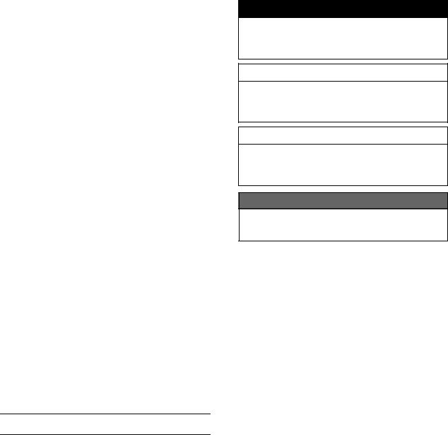
KX65-A1 Left Side View
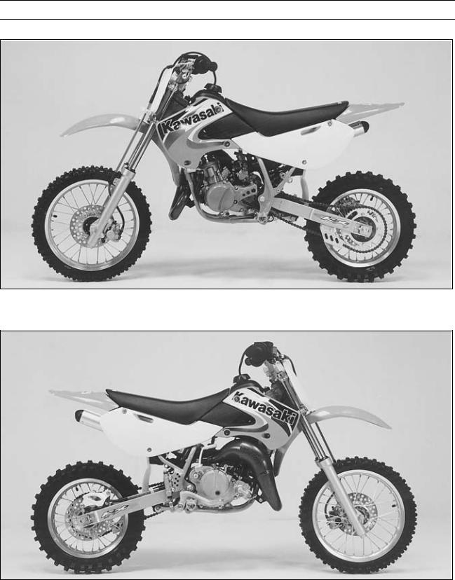
KX65-A1 Right Side View

1-6 GENERAL INFORMATION
General Specifications
Items |
KX65-A1 A2 |
KX65-A3 A6, A6F |
|
ABF |
|
||
|
|
|
|
Dimensions |
|
|
|
Overall Length |
1 580 mm |
1 590 mm |
|
Overall Width |
690 mm (KX65-A1), 730 mm (KX65-A2) |
760 mm |
|
Overall Height |
925 mm (KX65-A1), 935 mm (KX65-A2) |
955 mm |
|
Wheelbase |
1 110 mm |
1 120 mm |
|
Road Clearance |
270 mm (KX65-A1), 280 mm (KX65-A2) |
305 mm |
|
Seat Height |
720 mm (KX65-A1), 730 mm (KX65-A2) |
760 mm |
|
Dry Mass |
53 kg |
57 kg (KX65-A3 |
A8F) |
Curb Mass |
– |
60 kg (KX65A9F ) |
|
Front |
26.5 kg |
28.5 kg |
|
Rear |
29.5 kg |
31.5 kg |
|
Fuel Tank Capacity |
3.8 L |
← |
|
Engine |
|
|
|
Type |
2-stroke, single cylinder, piston reed valve |
← |
|
Cooling System |
Liquid-cooled |
← |
|
Bore and Stroke |
44.5 × 41.6 mm |
← |
|
Displacement |
64 cm³ |
← |
|
Compression Ratio |
8.4: 1 |
← |
|
Carburetion System |
MIKUNI VM24SS |
← |
|
Starting System |
Primary kick |
← |
|
Ignition System |
MAGNETO CDI |
← |
|
Ignition Timing |
20.5° BTDC @6 000 r/min (rpm) |
← |
|
|
|
20.5ºBTDC |
|
|
|
@7 100 r/min (rpm) |
|
|
|
(KX65A6F |
) |
Spark Plug |
NGK BR10EG (US) NGK B10EG |
← |
|
|
|
NGK BR10EG |
|
|
|
(KX65A6F |
) |
Port Timing |
|
|
|
Intake: |
|
|
|
Open |
Full open |
← |
|
Close |
— |
← |
|
Scavenging: |
|
|
|
Open |
61.8° BBDC |
← |
|
Close |
61.8° ABDC |
← |
|
Duaration |
123.6° |
← |
|
Exhaust: |
|
|
|
Open |
91.5° BBDC |
← |
|
Close |
91.5° ABDC |
← |
|
Duaration |
183° |
← |
|
Lubrication System |
Petrol mix (32:1) |
← |
|
(Gasoline : Oil) |
|
|
|
|
|
|
|
|
GENERAL INFORMATION 1-7 |
||
General Specifications |
|
|
|
|
|
|
|
|
|
|
|
Items |
KX65-A1 A2 |
KX65-A3 A6, A6F |
|
ABF |
|||
|
|
||
Drive Train |
|
|
|
Primary Reduction System: |
|
|
|
Type |
Gear |
← |
|
Reduction Ratio |
3.500 (77/22) |
← |
|
Clutch Type |
Wet, multi disc |
← |
|
Transmission: |
|
|
|
Type |
6-speed, constant mesh, return shift |
← |
|
Gear Ratios: |
|
|
|
1st |
2.846 (37/13) |
← |
|
2nd |
2.125 (34/16) |
← |
|
3rd |
1.722 (31/18) |
← |
|
4th |
1.428 (30/21) |
← |
|
5th |
1.217 (28/23) |
← |
|
6th |
1.083 (26/24) |
← |
|
Final Drive System: |
|
|
|
Type |
Chain drive |
← |
|
Reduction Ratio |
3.538 (46/13) |
3.615 (47/13) |
|
Overall Drive Ratio |
13.416 @Top gear |
13.703 @Top gear |
|
Transmission Oil: |
|
|
|
Grade |
API SG, SH, SJ, SL or SM with JASO MA, |
← |
|
|
MA1 or MA2 |
||
|
|
||
Viscosity |
SAE 10W-40 |
← |
|
Capacity |
0.5 L |
← |
|
Frame |
|
|
|
Type |
Tubular, semi-double cradle |
← |
|
Steering Angle |
40° to either side |
← |
|
Caster (Rake Angle) |
26.5° |
27° |
|
Trail |
60 mm |
← |
|
Front Tire: |
|
|
|
Size |
60/100-14 30M |
← |
|
Type |
tube type |
← |
|
Rear Tire: |
|
|
|
Size |
80/100-12 41M |
← |
|
Type |
tube type |
← |
|
Rim Size: |
|
|
|
Front |
14 × 1.40 |
← |
|
Rear |
12 × 1.60 |
← |
|
Front Suspension: |
|
|
|
Type |
Telescopic fork |
← |
|
Wheel Travel |
210 mm |
← |
|
Rear Suspension: |
|
|
|
Type |
Swingarm (Uni-trak) |
← |
|
Wheel Travel |
225 mm |
240 mm |
|

1-8 GENERAL INFORMATION
General Specifications
Items |
|
KX65-A1 |
A2 |
KX65-A3 A6, A6F |
|
ABF |
|||
|
|
|
|
|
Brake Type: |
|
|
|
|
Front and Rear |
Single disc |
|
|
← |
Effective Disc Diameter: |
|
|
|
|
Front |
154.8 mm |
|
|
← |
Rear |
146 mm |
|
|
← |
Specifications are subject to change without notice, and may not apply to every country. US: United States Model

GENERAL INFORMATION 1-9
Periodic Maintenance Chart
The maintenance must be done in accordance with this chart to keep the motorcycle in good running condition.
FREQUENCY |
After |
Every |
Every |
Every |
|
|
each |
3 races |
5 races |
10 races |
As |
OPERATION |
race (or |
(or 7.5 |
(or 12.5 |
(or 25 |
required |
|
2.5 hr.) |
hr.) |
hr.) |
hr.) |
|
Clutch - adjust |
• |
|
|
|
|
|
|
|
|
|
|
Clutch and friction plates - inspect † |
|
• |
R |
|
|
|
|
|
|
|
|
Throttle cable - adjust |
• |
|
|
|
|
|
|
|
|
|
|
Spark plug - clean, gap † |
• |
R |
|
|
|
|
|
|
|
|
|
Air cleaner element - clean |
• |
|
|
|
|
|
|
|
|
|
|
Air cleaner element - replace |
|
When damaged |
|
||
Carburetor - inspect/adjust |
• |
|
|
|
|
|
|
|
|
|
|
Transmission oil - change |
|
• |
|
|
|
|
|
|
|
|
|
Piston and piston ring - clean/inspect † |
|
• |
R |
|
|
|
|
|
|
|
|
Cylinder head, cylinder - inspect |
|
• |
|
|
|
|
|
|
|
|
|
Muffler body - clean/inspect † |
• |
|
|
|
|
Muffler body packing - change |
|
• |
|
|
|
|
|
|
|
|
|
Small end bearing - inspect † |
|
• |
|
R |
|
|
|
|
|
|
|
Kick pedal and shift pedal - clean |
• |
|
|
|
|
|
|
|
|
|
|
Exhaust pipe O-ring - replace |
|
• |
|
|
|
|
|
|
|
|
|
Engine sprocket - inspect † |
• |
|
|
|
|
Coolant - inspect † |
• |
|
|
|
R |
|
|
|
|
|
|
Water hoses, connections - inspect † |
• |
|
|
|
|
|
|
|
|
|
|
Reed valve - inspect † |
• |
|
|
|
|
|
|
|
|
|
|
Brake adjustment - inspect † |
• |
|
|
|
|
|
|
|
|
|
|
Brake pad wear - inspect † |
|
|
• |
|
|
Brake fluid level - inspect † |
|
• |
|
|
|
|
|
|
|
|
|
Brake fluid - change |
|
Every 2 years |
|
||
Brake master cylinder cup and dust seal - replace |
|
Every 2 years |
|
||
Brake caliper fluid seal and dust seal - replace |
|
Every 2 years |
|
||
Brake hose - replace |
|
Every 4 years |
|
||
Brake hoses, connections - inspect † |
• |
|
|
|
|
|
|
|
|
|
|
Spoke tightness and rim runout - inspect † |
• |
|
|
|
|
|
|
|
|
|
|
Drive chain - adjust |
• |
|
|
|
|
|
|
|
|
|
|
Drive chain - lubricate |
• |
|
|
|
|
Drive chain wear - inspect † |
|
|
• |
|
|
Drive chain slipper and guide - replace |
|
When damaged |
|
||
Front fork - inspect/clean |
• |
|
|
|
|
Front fork oil - change |
1st time after 2 races, then every 5 races |
||||
Nuts, bolts, fasteners - inspect † |
• |
|
|
|
|
|
|
|
|
|
|
Fuel system - clean |
• |
|
|
|
|
|
|
|
|
|
|
Fuel hose - replace |
|
Every 4 years |
|
||

1-10 GENERAL INFORMATION
Periodic Maintenance Chart
FREQUENCY |
After |
Every |
Every |
Every |
|
|
each |
3 races |
5 races |
10 races |
As |
OPERATION |
race (or |
(or 7.5 |
(or 12.5 |
(or 25 |
required |
|
2.5 hr.) |
hr.) |
hr.) |
hr.) |
|
Fuel hoses, connections - inspect † |
• |
|
|
|
|
|
|
|
|
|
|
|
|
|
|
|
|
Steering play - inspect † |
• |
|
|
|
|
|
|
|
|
|
|
|
|
|
|
|
|
Steering stem bearing - grease |
|
|
• |
|
|
|
|
|
|
|
|
Rear sprocket - inspect † |
|
|
• |
|
|
|
|
|
|
|
|
|
|
|
|
|
|
General lubrication - perform |
• |
|
|
|
|
|
|
|
|
|
|
|
|
|
|
|
|
Wheel bearing - inspect † |
|
|
|
• |
|
|
|
|
|
|
|
|
|
|
|
|
|
Swing arm and Uni-Trak linkage pivots - grease |
|
|
• |
|
|
|
|
|
|
|
|
|
|
|
|
|
|
Swing arm and Uni-Trak linkage pivots - inspect † |
|
|
• |
|
|
Rear shock oil - replace |
1st time after 2 races, then every 5 races |
||||
†: Replace, add, adjust, clean or torque if necessary. R: Replace

GENERAL INFORMATION 1-11
Torque and Locking Agent
Tighten all bolts and nuts to the proper torque using an accurate torque wrench. If insufficiently tightened, a bolt or nut may become damaged, strip an internal thread, or break and then fall out. The following table lists the tightening torque for the major bolts and nuts, and the parts requiring use of a non-permanent locking agent or liquid gasket.
When checking the tightening torque of the bolts and nuts, first loosen the bolt or nut by half a turn and then tighten to specified torque.
Letters used in the "Remarks" column mean:
L: Apply a non-permanent locking agent to the threads. Lh: Left-hand Threads.
S: Tighten the fasteners following the specified sequence.
Fastener |
|
Torque |
|
|
Remarks |
||
N·m |
kgf·m |
ft·lb |
|||||
|
|
||||||
Fuel System |
|
|
|
|
|
|
|
Rear Frame Mounting Bolts |
34 |
3.5 |
|
25 |
|
||
Carburetor Clamp Screws |
1.5 |
0.15 |
|
13 in·lb |
|
||
Carburetor Holder Mounting Bolts |
8.8 |
0.90 |
|
78 |
in·lb |
|
|
Air Cleaner Housing Plate Nuts |
3.0 |
0.31 |
|
27 |
in·lb |
|
|
Air Cleaner Housing Mounting Bolts |
8.8 |
0.90 |
|
78 |
in·lb |
|
|
Reed Valve Screws |
9.8 |
1.0 |
|
87 in·lb |
|
||
Cooling System |
|
|
|
|
|
|
|
Radiator Mounting Bolts |
8.8 |
0.90 |
|
78 |
in·lb |
|
|
Shroud Mounting Bolts |
8.8 |
0.90 |
|
78 |
in·lb |
|
|
Air Bleeder Bolt |
|
|
|
|
in·lb |
|
|
8.8 |
0.90 |
|
78 |
|
|||
Water Pump Cover Bolts |
8.8 |
0.90 |
|
78 in·lb |
|
||
Water Pump Impeller Bolt |
8.3 |
0.85 |
|
73 |
in·lb |
|
|
Water Hose Clamp Screws |
1.5 |
0.15 |
|
13 in·lb |
|
||
Coolant Drain Plug (Water Pump) |
8.8 |
0.90 |
|
78 in·lb |
|
||
Water Pump Cover Fitting Bolts |
5.9 |
0.60 |
|
52 |
in·lb |
|
|
Engine Top End |
|
|
|
|
|
|
|
Cylinder Head Nuts |
25 |
2.5 |
|
18 |
|
||
Spark Plug |
26 |
2.6 |
|
19 |
|
||
Cylinder Nuts |
25 |
2.5 |
|
18 |
|
||
Muffler Mounting Bolts |
8.8 |
0.90 |
|
78 |
in·lb |
L |
|
Expansion Chamber Damper Mounting Bolt, |
8.8 |
0.90 |
|
78 |
in·lb |
|
|
Nut |
|
|
|||||
|
|
|
|
|
|
||
Inner Pipe Mounting Bolts |
5.9 |
0.6 |
|
52 |
in·lb |
L |
|
Engine Right Side |
|
|
|
|
|
|
|
Primary Gear Nut (KX65A6F ) |
49 |
5.0 |
|
36 |
Lh |
||
Clutch Spring Bolts |
9.3 |
0.95 |
|
82 |
in·lb |
|
|
Clutch Hub Bolt |
64 |
6.5 |
|
47 |
|
||
Ratchet Guide Bolt |
8.8 |
0.90 |
|
78 |
in·lb |
|
|
Ratchet Guide Screw |
5.2 |
0.53 |
|
46 in·lb |
|
||
Kick Pedal Bolt |
12 |
1.2 |
|
104 in·lb |
|
||
|
|
||||||
Right Engine Cover Bolts |
8.8 |
0.90 |
|
78 |
in·lb |
|
|
Oil Filler Cap |
1.5 |
0.15 |
|
13 |
in·lb |
|
|
Gear Set Lever Screw |
8.8 |
0.90 |
|
78 in·lb |
|
||
|
|
|
|
|
|
|
|

1-12 GENERAL INFORMATION
Torque and Locking Agent
Fastener |
|
Torque |
|
Remarks |
|
N·m |
kgf·m |
ft·lb |
|||
|
|
||||
Engine Removal/Installation |
|
|
|
|
|
Engine Mounting Nuts |
25 |
2.5 |
18 |
|
|
Engine Mounting Nuts (KX65-A3 ) |
29 |
3.0 |
21 |
|
|
Swing Arm Pivot Shaft Nut |
69 |
7.0 |
51 |
|
|
Engine Bottom End/Transmission |
|
|
|
|
|
Cylinder Stud |
– |
– |
– |
L (Planted |
|
|
|
|
|
Side) |
|
Crankcase Bolts |
8.8 |
0.90 |
78 in·lb |
|
|
Shift Pedal Bolt |
8.8 |
0.90 |
78 in·lb |
|
|
Engine Oil Drain Plug |
20 |
2.0 |
15 |
|
|
Bearing Retaining Screws |
8.8 |
0.90 |
78 in·lb |
|
|
Shift Drum Operating Plate Bolt |
24 |
2.4 |
17 |
L |
|
Shift Drum Plate Mounting Screws |
5.2 |
0.53 |
46 in·lb |
L |
|
Gear Set Lever Screw |
8.8 |
0.90 |
78 in·lb |
|
|
Flywheel Nut |
29 |
3.0 |
21 |
|
|
Wheels/Tires |
|
|
|
|
|
Front Axle Nut |
79 |
8.0 |
58 |
|
|
Rear Axle Nut |
79 |
8.0 |
58 |
|
|
Spoke Nipple |
Not less |
Not less |
Not less |
|
|
|
than 1.5 |
than 0.15 |
than 13 |
|
|
|
|
|
in·lb |
|
|
Final Drive |
|
|
|
|
|
Rear Axle Nut |
79 |
8.0 |
58 |
|
|
Rear Sprocket Bolts |
26 |
2.7 |
20 |
|
|
Brakes |
|
|
|
|
|
Caliper Mounting Bolts (Front, Rear) |
25 |
2.5 |
18 |
|
|
Brake Hose Banjo Bolts |
25 |
2.5 |
|
|
|
18 |
|
||||
Master Cylinder Clamp Bolts |
8.8 |
0.90 |
78 in·lb |
S |
|
Rear Master Cylinder Mounting Screws |
9.8 |
1.0 |
87 in·lb |
|
|
Rear Master Cylinder Push Rod Locknut |
18 |
1.8 |
13 |
|
|
Brake Disc Mounting Bolts (Front, Rear) |
9.8 |
1.0 |
87 in·lb |
L |
|
Caliper Bleed Valves (Front, Rear) |
7.8 |
0.80 |
69 in·lb |
|
|
Brake Pedal Mounting Bolt |
|
|
|
|
|
25 |
2.5 |
18 |
|
||
Brake Lever Adjuster locknut |
4.9 |
0.50 |
43 in·lb |
|
|
Brake Pad Bolts |
|
|
|
|
|
18 |
1.8 |
13 |
|
||
Suspension |
|
|
|
|
|
Front Fork Clamp Bolts (Upper) |
20 |
2.0 |
14 |
|
|
Front Fork Clamp Bolt (Lower) |
29 |
3.0 |
22 |
|
|
Fork Bottom Allen Bolt |
20 |
2.0 |
14 |
L |
|
Front Fork Top Plug |
22 |
2.2 |
16 |
|
|
Swingarm Pivot Shaft Nut |
69 |
7.0 |
51 |
|
|
Rear Shock Absorber Mounting Bolt (Upper) |
39 |
4.0 |
29 |
|
|
Rear Shock Absorber Mounting Nut (Lower) |
34 |
3.5 |
25 |
|
|
Tie-rod Mounting Nuts (Front, Rear) |
59 |
6.0 |
43 |
|
GENERAL INFORMATION 1-13
Torque and Locking Agent
Fastener |
|
Torque |
|
|
Remarks |
|
N·m |
kgf·m |
ft·lb |
||||
|
|
|||||
Rocker Arm Pivot Nut |
83 |
8.5 |
61 |
|
||
Caliper Mounting Bolts |
25 |
2.5 |
18 |
|
||
Rear Frame Mounting Bolts |
34 |
3.5 |
25 |
|
||
Steering |
|
|
|
|
|
|
Steering Stem Head Nut |
44 |
4.5 |
33 |
|
||
Steering Stem Nut |
2.9 |
0.30 |
26 |
in·lb |
|
|
Handlebar Clamp Bolts |
25 |
2.5 |
18 |
|
||
Clutch Lever Clamp Bolts |
8.8 |
0.90 |
78 |
in·lb |
|
|
Front Fork Clamp Bolts (Upper) |
20 |
2.0 |
15 |
|
||
Front Fork Clamp Bolts (Lower) |
29 |
3.0 |
22 |
|
||
Electrical System |
|
|
|
|
|
|
Magneto Cover Bolts |
8.8 |
0.90 |
78 in·lb |
|
||
Flywheel Nut |
29 |
3.0 |
21 |
|
||
Stator Plate Mounting Screws |
4.9 |
0.50 |
43 |
in·lb |
|
|
Ignition Coil Mounting Bolts |
8.8 |
0.90 |
78 |
in·lb |
|
|
CDI Unit Mounting Bolts |
8.8 |
0.90 |
78 |
in·lb |
|
|
Spark Plug |
26 |
2.6 |
19 |
|
||
The table below relating tightening torque to thread diameter, lists the basic torque the bolts and nuts. Use this table for only the bolts and nuts which do not require a specific torque value. All of the values are for use with dry solvent-cleaned threads.
Basic Torque for General Fasteners
Threads dia. |
|
|
|
|
Torque |
|
|
|
|||
(mm) |
N·m |
kgf·m |
ft·lb |
||||||||
5 |
3.4 |
|
4.9 |
|
0.35 |
|
0.50 |
|
30 |
43 in·lb |
|
|
|
|
7.8 |
|
|
|
0.80 |
|
52 |
69 in·lb |
|
6 |
5.9 |
|
0.60 |
|
|||||||
8 |
14 |
|
19 |
|
1.4 |
|
1.9 |
|
10.0 |
13.5 |
|
10 |
25 |
|
34 |
|
2.6 |
|
3.5 |
|
19.0 |
25 |
|
12 |
44 |
|
61 |
|
4.5 |
|
6.2 |
|
33 |
|
45 |
14 |
73 |
|
98 |
|
7.4 |
10.0 |
|
54 |
|
72 |
|
16 |
115 |
|
155 |
|
11.5 |
|
16.0 |
|
83 |
115 |
|
18 |
165 |
|
225 |
|
17 |
|
23 |
|
125 |
|
165 |
20 |
225 |
|
325 |
|
23 |
|
33 |
|
165 |
|
240 |

1-14 GENERAL INFORMATION
Special Tools and Sealants
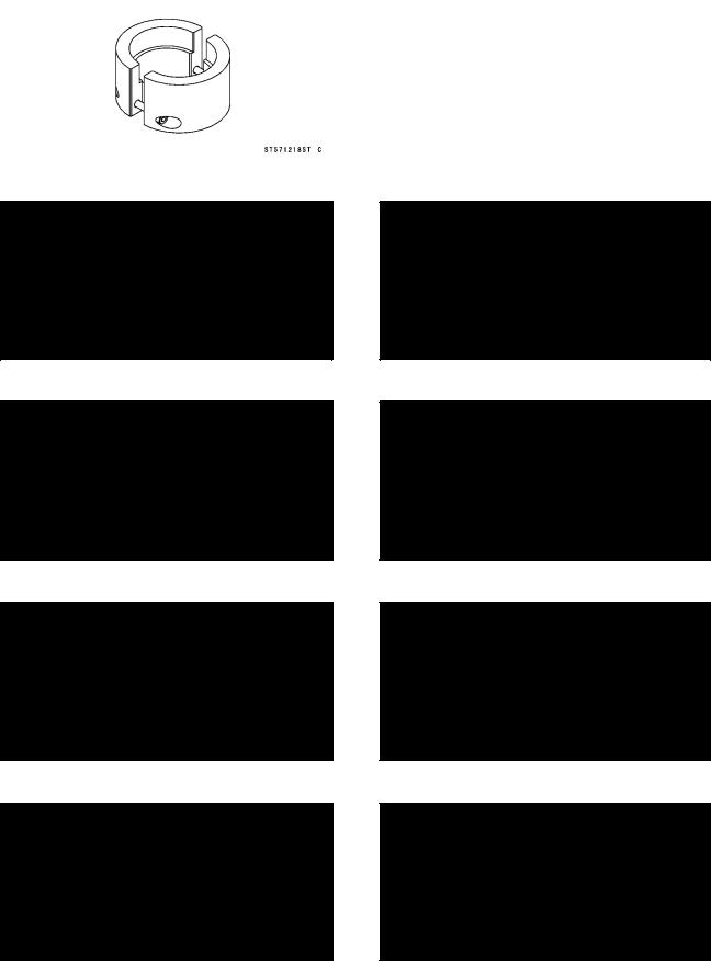
Bearing Puller Adapter: |
|
Fork Cylinder Holder Handle: |
57001-136 |
57001-183 |
|
|
|
|
Steering Stem Bearing Driver: 57001-137
Flywheel Puller, M12 × 1.75: 57001-252
Inside Circlip Pliers: 57001-143
Piston Pin Puller Assembly: 57001-910
Outside Circlip Pliers: 57001-144
Fork Cylinder Holder Adapter: 57001-1011
|
|
|
Bearing Puller: |
|
Oil Seal & Bearing Remover: |
57001-158 |
57001-1058 |
|
|
|
|
|
|
GENERAL INFORMATION 1-15 |
Special Tools and Sealants |
|
|
|
|
|
Rim Protector: |
|
Hook Wrench R37.5, R42: |
57001-1063 |
57001-1101 |
|
|
|
|
Bead Breaker Assembly: 57001-1072
Head Pipe Outer Race Driver,  46.5: 57001-1106
Head Pipe Outer Race Press Shaft: 57001-1075
Head Pipe Outer Race Remover ID > 37 mm: 57001-1107
Steering Stem Bearing Driver Adapter,  29.7: 57001-1092
Bearing Driver Set: 57001-1129
Steering Stem Nut Wrench: 57001-1100
Fork Outer Tube Weight: 57001-1218
1-16 GENERAL INFORMATION
Special Tools and Sealants
Front Fork Oil Seal Driver: |
Peak Voltage Adapter: |
57001-1219 |
57001-1415 |
|
|
|
Jack: |
|
Crank Shaft Jig: |
57001-1238 |
57001-1439 |
|
|
|
|
Fork Oil Level Gauge: 57001-1290
Graduated Cylinder & Tube: 57001-1584
Crankcase Splitting Tool Assembly: 57001-1362
Flywheel & Pulley Holder: 57001-1605
|
|
|
Hand Tester: |
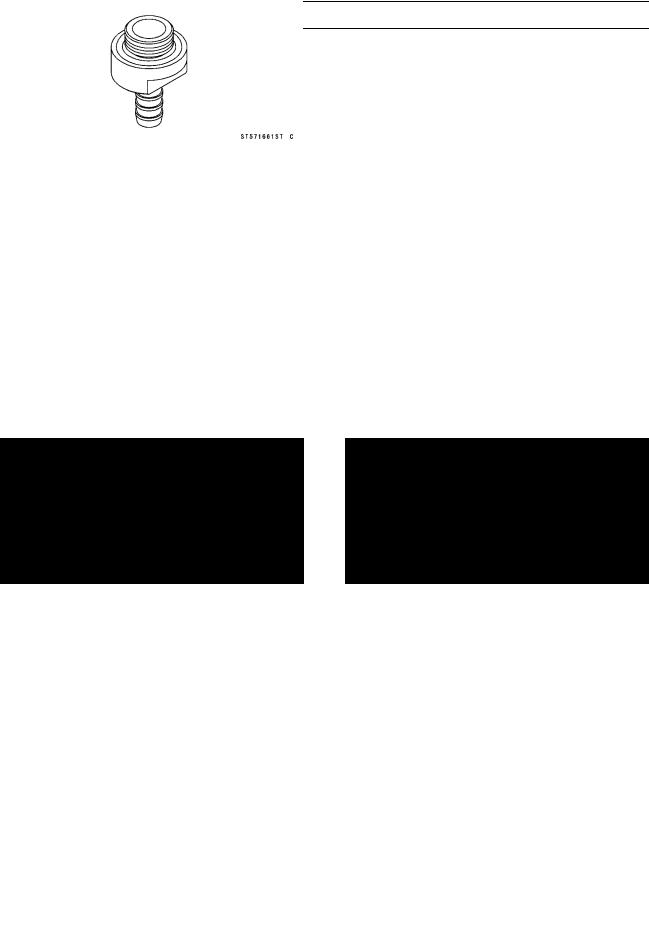
|
Fuel Level Gauge Adapter, M16 × 1: |
57001-1394 |
57001-1661 |
|
|
|
|
|
|
GENERAL INFORMATION 1-17 |
Special Tools and Sealants |
|
|
|
|
|
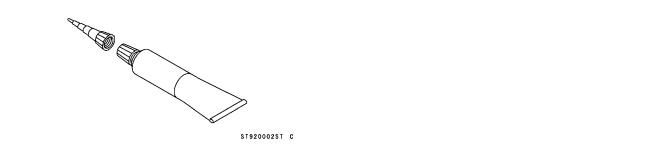
Liquid Gasket, TB1211: |
|
Liquid Gasket, TB1105B: |
56019-120 |
92104-002 |
|
|
|
|

1-18 GENERAL INFORMATION
Cable, Wire and Hose Routing
1.Throttle Cable
2.Carburetor
3.Breather Hose
4.Air Vent Hose
5.Overflow Hose
6.The hoses are passed from the left side of the engine through the clamp in order of the air vent hose, the overflow hose and the breather hose as shown in figure.
7.CDI Unit (KX65-A1 A6)
8.Clamp
9.Rubber Damper (Note its installing direction.)
10.Clutch Cable
11.Engine Stop Button Lead
12.Band
13.Install the kick pedal so that it should be parallel to the frame as shown in figure.
14.KX65-A1 A2
15.KX65-A3 A6
GENERAL INFORMATION 1-19
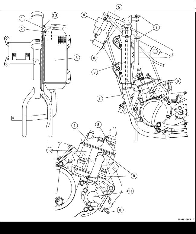
Cable, Wire and Hose Routing
1.Breather Hose
2.Run the throttle cable under the breather hose.
3.Radiator
4.CDI Unit (KX65-A1 A6)
5.Clamp (KX65-A1 A6)
6.Throttle Cable
7.Clamp as shown in figure. (Be sure the clamp screw position is inside.)
8.Clamp as shown in figure.
9.Cylinder Head
10.Cylinder
11.Water Pump Cover
12.Engine Stop Button Lead (KX65A6F )
1-20 GENERAL INFORMATION
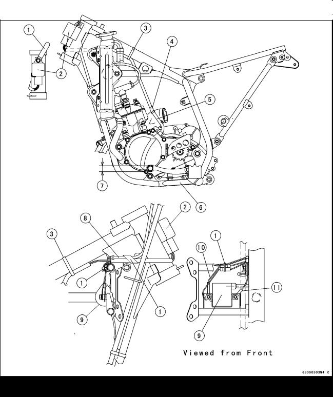
Cable, Wire and Hose Routing
1.Clamp
2.CDI Unit (KX65-A1 A6)
3.Band
4.Clamp the magneto leads at the upper part of the left on the carburetor holder.
5.Magneto Leads
6.Shift Pedal
7.19 ±10 mm (Shift Pedal Position)
8.Engine Stop Button Lead
9.Ignition Coil
10.Engine Stop Button Lead Ground
11.CDI Unit Ground Lead
GENERAL INFORMATION 1-21
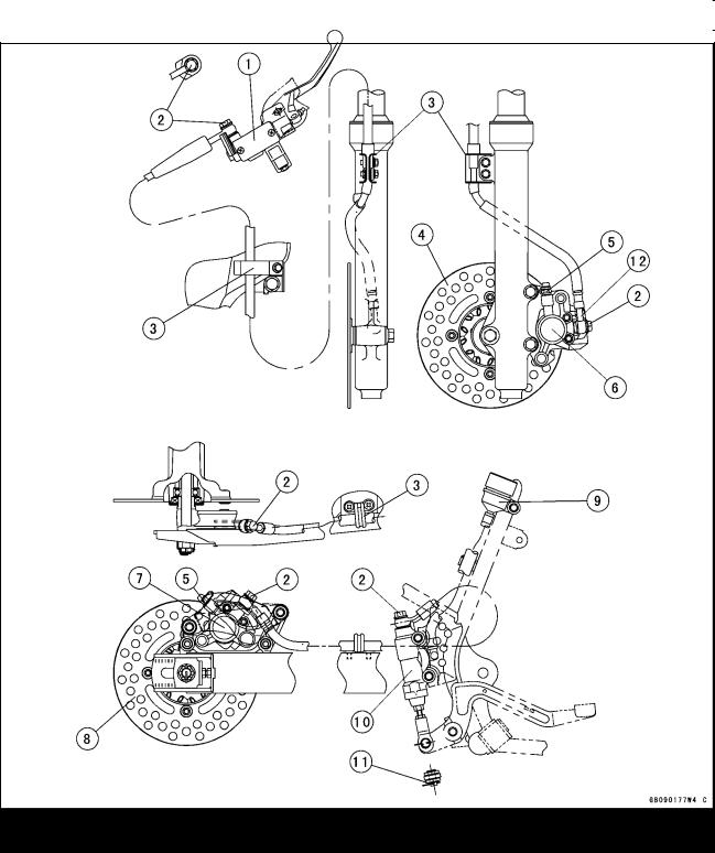
Cable, Wire and Hose Routing
1.Front Brake Reservoir
2.Banjo Bolts
3.Clamp
4.Front Brake Disk
5.Bleed Valves
6.Front Brake Caliper
7.Rear Brake Caliper
8.Rear Brake Disk
9.Rear Brake Reservoir
10.Rear Brake Master Cylinder
11.Bend the cotter pin end by along the joint pin.
12.White paint mark
1-22 GENERAL INFORMATION
Cable, Wire and Hose Routing
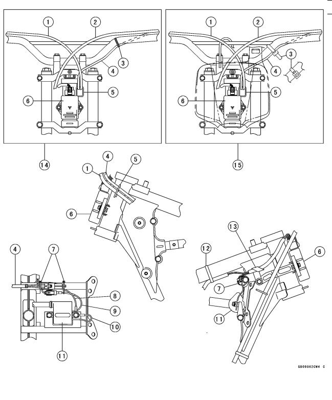
KX65A6F
|
|
|
|
|
1. |
Throttle Cable |
9. |
Ignition Coil Primary Lead |
|
2. |
Clutch Cable |
10. |
Ignition Coil Ground Lead |
|
3. |
Band |
11. |
Ignition Coil |
|
4. |
Engine Stop Button Lead |
12. |
Band |
|
5. Clamp |
13. Clamp the Magneto Lead |
|
||
6. CDI unit |
14. KX65A6F A8F |
|
||
7. Band |
15. KX65A9F |
|
||
8. |
CDI unit Ground Lead |
|
|
|
Loading...