


Ninja 650 ABS 2013
Table of contents
 Loading...

Quick Reference Guide
GENERAL INFORMATION j
HOW TO RIDE THE MOTORCYCLE j
SAFE OPERATION j
MAINTENANCE AND ADJUSTMENT j
STORAGE j
TROUBLESHOOTING GUIDE j
This Quick Reference Guide will
assist you in finding the information
you’re looking for.
A Table of Contents is included after
the Foreword.
Whenever you see the symbols
shown below, heed their instructions!
Always follow safe operating and main-
tenance practices.
DANGER
DANGER indicates a hazardous
situation which, if not avoided,
will result in death or serious in-
jury.
WARNING
WARNING indicates a hazardous
situation which, if not avoided,
could result in death or serious
injury.
NOTICE
NOTICE is used to address prac-
tices not related to personal in-
jury.
NOTE
○
NOTE indicates information that may
help or guide you in the operation or
service of the vehicle.
WARNING
Engine exhaust, some of its
constituents, and certain vehi-
cle components contain or emit
chemicals known to the State of
California to cause cancer and
birth defects or other reproduc-
tive harm.
NOTICE
THIS PRODUCT HAS BEEN
MANUFACTURED FOR USE IN A
REASONABLE AND PRUDENT
MANNER BY A QUALIFIED OP-
ERATOR AND AS A VEHICLE
ONLY.

FOREWORD
Congratulations on your purchase of a new Kawasaki motorcycle. Your new mo-
torcycle is the product of Kawasaki’s advanced engineering, exhaustive testing,
and continuous striving for superior reliability, safety and performance.
Please read this Owner ’s Manual carefully before riding so that you will be
thoroughly familiar with the proper operation of your motorcycle’s controls, its fea-
tures, c apabilities, and limita tio ns. This manual offers many safe riding tips, but its
purpose is not to provide instruction in all the techniques and skills required to ride
a motorcycle safely. Kawasaki strongly recommends that all operators of this vehi-
cle enroll in a motorcycle rider training p ro gram to attain awareness of the mental
and physical requirements necessary for safe motorcycle operation.
To ensure a long, trouble-free life for your motorcycle, give it the proper care and
maintenance described in this manual. For those who would like more detailed in-
formation on their Kawasaki Motorcycle, a Service Manual is available for purchase
from any authorized Kawasaki motorcycle dealer. The Service Manual contains de-
tailed disassembly and maintenance information. Those who plan to do their own
work should, of course, be competent mechanics and possess the special tools
described in the Service Manual.
Keep this Owner’s Manual aboard your motorcycle at all times so that you can
refer to it whenever you need information.

This manual should be considered a permanent part of the motorcycle and should
remain with th e motorcycle whe n it is sold.
All rights reserved. No part of this publication may be reproduced without our
prior written permission.
This publication includes the latest information available at the time of printing.
However, there may be minor differences between the actual product and illustra-
tions and text in this manual.
All products are subject to change without prior notice or obligation.
KAWASAKI HEAVY INDUSTRIES, LTD.
Motorcycle & Engine Company
© 2013 Kawasaki Heavy Industries, Ltd. Apr. 12, 2013. (1)

TABLE OF CO NTE NTS
SPECIFICATIONS............................... 9
SERIAL NUMBER L OCATIONS......... 13
LOCATION OF PARTS....................... 14
LOADING AND ACCESSORIES
INFORMATION ................................ 17
GENERAL INFORMATION................. 20
Meter Instruments ............................ 20
Tachometer................................... 21
Multifunction Meter........................... 22
Multifunction Display..................... 24
Warning/Indicator Lights: .............. 31
Keys ................................................. 34
Ignition Switch/Steering Lock ........... 35
Right Handlebar Switches ................ 37
Engine Stop Switch: ..................... 37
Starter Button: .............................. 38
Left Handlebar Switches .................. 38
Dimmer Switch: ............................ 38
Turn Signal Switch:....................... 39
Horn Button: ................................. 39
Passing Button: ............................ 39
Hazard Switch: ............................. 39
Brake/Clutch Lever Adjusters........... 40
Fuel Tank Cap .................................. 41
Fuel Tank ......................................... 42
Fuel Requirement ......................... 43
Stand................................................ 47
Seats................................................ 48
Helmet Hooks................................... 50
Tool Kit ............................................. 51
Tying Hooks ..................................... 52
Windshield........................................ 52
BREAK-IN ........................................... 54
HOW TO RIDE THE MOTORCYCLE .56
Starting the Engine .......................... 56
Jump Starting ................................... 58
Moving Off........................................ 61
Shifting Gears .................................. 62
Braking............................................. 64

Anti-lock Brake System (ABS) for
models equipped with ABS........... 65
Yellow ABS Indicator Light:........... 67
Stopping the Engine ......................... 68
Stopping the Motorcycle in an
Emergency ................................... 69
Parking............................................. 70
Catalytic Converter........................... 72
SAFE OPERATION............................. 74
Safe Riding Technique ..................... 74
Daily Checks .................................... 77
Additional Considerations for High
Speed Operation .......................... 80
MAINTENANCE AND ADJUSTMENT 82
Periodic Maintenance Chart ............. 87
Engine Oil ........................................ 99
Cooling System ................................ 105
Spark Plugs...................................... 113
Evaporative Emission Control
System (California model only)..... 114
Kawasaki Clean Air System ............. 115
Valve Clearance ............................... 116
Air Cleaner ....................................... 117
Throttle Control System ................... 118
Engine Vacuum Synchronization ..... 121
Idle Speed ........................................ 121
Clutch............................................... 123
Drive Chain ...................................... 125
Brakes.............................................. 132
Brake Light Switches........................ 136
Front Fork......................................... 139
Rear Shock Absorber ....................... 140
Wheels ............................................. 143
Battery.............................................. 148
Headlight Beam................................ 153
Fuses ............................................... 155
General Lubrication.......................... 157
Cleaning Your Motorcycle ................ 159
Bolt and Nut Tightening.................... 164
STORAGE........................................... 166
TROUBLESHOOTING GUIDE............ 169
YOUR WARRANTY/OWNER
SATISFACTION ........................... 170
REPORTING SAFETY DEFECTS ...... 176
ENVIRONMENTAL PROTECTION ..... 177
MAINTENANCE RECORD ................. 178

LOCATION OF LABELS..................... 186

SPECIFICATIONS 9
SPECIFICATIONS
PERFORMAN
CE
Minimum Turning Radius
2.7 m (106.
3in.)
DIMENSIO
NS
Overall L
ength
2110mm(8
3.07 in.)
Overall W
idth
770 mm (30
.31 in.)
Overall H
eight
1 180 mm (4
6.46 in.)
Wheelbase
1 410 mm (
55.51 in.)
Road Clearance
130 mm (5
.12 in.)
Curb Mass
(E) 209 kg (4
61 lb)
(F) 211 kg (4
65 lb)
ENGINE
Type
DOHC, 4-valve, 2-cylinder, 4-stroke, liquid-cooled
Displacement
649 cm
3
(39.6 cu in.)
Bore × S
troke
83.0 × 6
0.0 mm (3.27 × 2.36 in.)
Compr
ession Ratio 10.8 : 1

10 SPECIFICATIONS
Starting System Electric starter
Cylinder Numbering Method Left to right, 1-2
Firing Order 1-2
Fuel System FI (Fuel Injection)
Ignition System Battery and coil (transistorized ignition)
Ignition Timing 10° BTDC @1 300 r/min (rpm) ∼
(Electronically advan ced) 37° BTDC @5 000 r/min (rpm)
Spark Plugs NGK CR9EIA-9
Lubrication System Forced lubrication (semi-dry sump)
Engine Oil
Type :
API SG, SH, SJ, SL or SM with JASO MA, MA1
or MA2
Viscosity:
SAE 10W-40
Capacity: 2.3 L (2.4 US qt)
Coolant Capacity 1.2 L (1.3 US qt)
TRANSMISSION
Transmission Type
6-speed, constant mesh, return shift
Clutch Type
Wet, multi disc

SPECIFICATIONS 11
Driving System Chain drive
Primary Reduction Ratio 2.095 (88/42)
Final R eduction Ratio 3.067 (46/15)
Overall D rive Rati o 5.473 (Top gear)
Gear Ratio 1st 2.438 (39/16)
2nd 1.714 (36/21)
3rd 1.333 (32/24)
4th 1.111 (30/27)
5th 0.966 (28/29)
6th 0.852 (23/27)
FRAME
Castor 25°
Trail 110 mm (4.3 in.)
Tire Size: Front 120/70ZR17 M/C (58 W)
Rear 160/60ZR17 M/C (69 W)
Rim Size: Front J17M/C × MT3.50
Rear J17M/C × MT4.50

12 SPECIFICATIONS
Fuel Tank Capacity 16 L (4.2 US gal)
ELECTRICAL EQUIPMENT
Battery 12 V 10 Ah
Headlight 12 V 55 W/55 W (Hi/Lo)
Tail/Brake Light LED
Even if one of LED (Light Emitting Diode) tail/brake light does not go on, consult
with an authorized Kawasaki dealer.
Specifications are subject to change without notice.
(E): EX650E
(F): EX650F
SERIAL NUMBER LOCATIONS 13
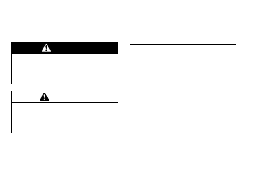
SERIAL NUMBER LOCATIONS
The engine and frame serial numbers are used to register the motorcycle. They
are the only means of identifying your particular machine from others of the same
model type. These serial numbers may be needed by your dealer when ordering
parts. In the event of theft, the investigating authorities will require both numbers
as well as the model type and any peculiar features of your machine that can help
them id entify it.
Frame No.
A. Frame Number
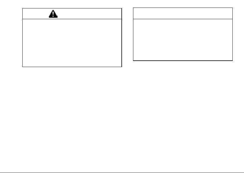
Engine N o.
A. Engine Number
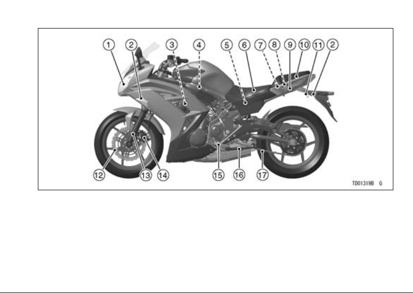
14 LOCATION OF PARTS
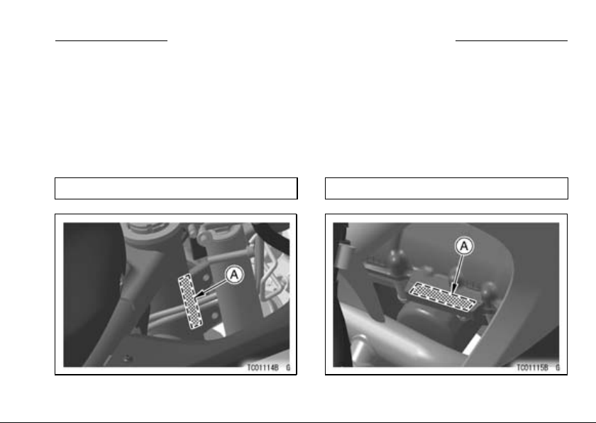
LOCATION OF PARTS
1. Clutch Lever
2. Left Handlebar S witches
3. Meter Instruments
4. Brake Fluid Reservoir (Front)
5. R ight Handlebar Switches
6. Fr on t Brake Lever
7. T hro ttle Grip
8. Ig nit ion Switch/Steering Lock
LOCATION OF PARTS 15
1. Headlight
2. Turn Signal Light
3. Spark Plugs
4. Air Cleaner
5. Battery
6. Rider’s Seat
7. H elmet Holding
Hooks
8. Tool Kit
9. Seat Lock
10. Passeng er ’s Seat
11. Tying Hooks
12. Brake Disc
13. Front Fork
14. Brake Caliper
15. Shift Pedal
16. Side Stand
17. Drive Chain
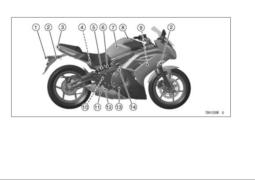
16 LOCATION OF PARTS
1. License Plate Light
2. Turn Signal Light
3. Tail/Brake L igh t
4. Brake Fluid Reservoir (R ear)
5. Rear Shock Absorber
6. Spring Preload Adjuster
7. Fuel Tank
8. Fuel Tank Cap
9. C oo lant Reserve Tank
10. R ear Brake Light Swi tch
11. Mu ff ler
12. R ear Brake Pedal
13. Oil Level Inspection Window
14. Id le Adjusting Screw
LOADING AND ACCESSORIES INFORMATION 17
LOADING AND ACCESSORIES INFORMATION
WARNING
Incorrect loading, improper in-
stallation or use of accessories,
or modification of your motorcy-
cle may result in an unsafe riding
condition. Before you ride the
motorcycle, make sure it is not
overloaded and that you have
followed these instructions.
With the exception of genuine
Kawasaki Parts and Accessories,
Kawasaki has no control over the
design or application of accessories.
In some cases, improper installation
or use of accessories, or motorcycle
modification, will void the motorcycle
warranty, can negatively affect per-
formance, and can even be illegal.
In selecting and using accessories,
and in loading the motorcycle, you are
personally responsible for your own
safety and the safety of other persons
involved.
NOTE
○
Kawasaki Parts and Accessories
have been specially designed for
use on Kawasaki motorcycles. We
strongly recommend that all parts
and accessories you add to your
motorcycle be genuine Kawasaki
components.
Because a motorcycle is s en sitive to
changes in weight and aerodynamic
forces, you must take extreme care in
carrying cargo, passengers and/or in

18 LOADING AND ACCESSORIES INFORMATION
fitting additional accessories. The fol-
lowing general guidelines have been
prepared to assist you in making your
determinations.
1. Any passenger should be thor-
oughly familiar with motorcycle op-
eration. The passenger can affect
control of the motorcycle by im-
proper positioning during cornering
and sudden movements. It is impor-
tant that the passenger sit still while
the motorcycle is in motion and not
interfere with the operation of the
motorcycle. Do not carry animals
on your motorcycle.
2. You should instruct any passenger
before riding to keep his feet on the
passenger footpegs and hold on to
the operator or seat strap. Do not
carry a passenger unless he or she
is tall enough to reach the footpegs
and footpegs are provided.
3. All baggage should be carried as
low as possible to r educe the effect
on the motorcycle center of gravity.
Baggage weight should also be dis-
tributed equally on both sides of the
motorcycle. Avoid carrying baggage
that extends beyond the rear of the
motorcycle.
4. Baggage should be securely at-
tached. Make sure that the baggage
will not move around while you are
riding. Recheck baggage security
as often as possible (not while the
motorcycle is in motion) and adjust
as necessary.
5. Do not carry heavy or bulky items on
a luggage rack. They are designed
for light items, and overloading can
affect handling due to changes in
weight distribution and aerodynamic
forces.

LOADING AND ACCESSORIES INFORMATION 19
6. Do not install accessories or carry
baggage that impairs the perfor-
mance of the motorcycle. Make
sure that you have not adversely
affected any lighting components,
road clearance, banking capability
(i.e., lean angle), control operation,
wheel travel, front fork movement,
or any other aspect of the motorcy-
cle’s operation.
7. Weight attached to the handlebar or
front fork will increase the mass of
the steering assembly and can r e-
sult in an unsafe riding condition.
8. Fairings, windshields, backrests,
and other large items have the ca-
pability of adversely affecting stabil-
ity and handling of the motorcycle,
not only because of their weight, but
also due to the aerodynamic forces
acting on these surfaces while the
motorcycle is in operation. Poorly
designed or installed items can re-
sult in an unsafe riding condition.
9. This motorcycle is not intended to
be equipped with a sidecar or to be
used to tow any tr ailer or other ve-
hicle. Kawasaki does not manu-
facture sidecars or trailers for mo-
torcycles and cannot predict the ef-
fects of such accessories on han-
dling or stability, but can only warn
thattheeffectscanbeadverseand
that Kawasaki cannot assume re-
sponsibility for the results of such
unintended use of the motorcycle.
Furthermore, any adverse effects on
motorcycle components caused by
the use of such accessories will not
be remedied under warranty.
Maximum Load
Weight of rider, passenger, baggage,
and accessories must not exceed 200 kg
(441 lb).
20 GENERAL INFORMATION
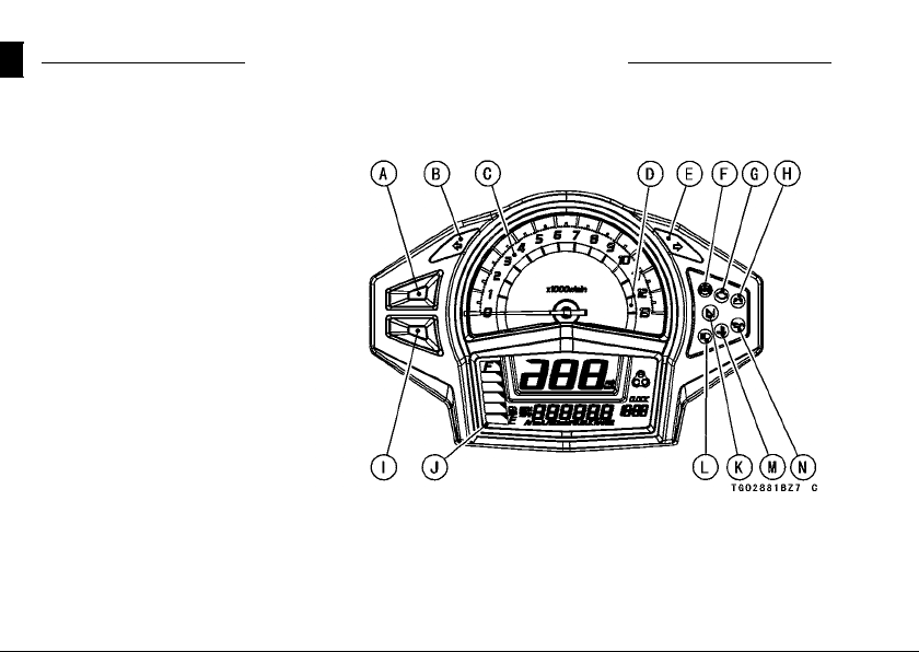
GENERAL INFORMATION
Meter Instruments
A. MODE Button
B. Green Left Turn Sign al
Indicator Light
C. Tachometer
D. Red Zone
E. Green Right Turn Signal
Indicator Light
F. Yellow ABS Indicator Light
(Only on ABS model)
G. Yellow Engine Warning
Indicator Light
H. Red Battery Voltage
Warning Indicator Light
I. RESET Button
J. Multifunction Meter
K. Green Neutral Indicator
Light
L. Blue High Beam Indicator
Light
M. Red Coolant Temperature
Warning Indicator Light
N. Red Oil Pressure Warning
Indicator Light
GENERAL INFORMATION 21
NOTE
○
For safety, do not operate the instru-
ment buttons while riding the motor-
cycle.
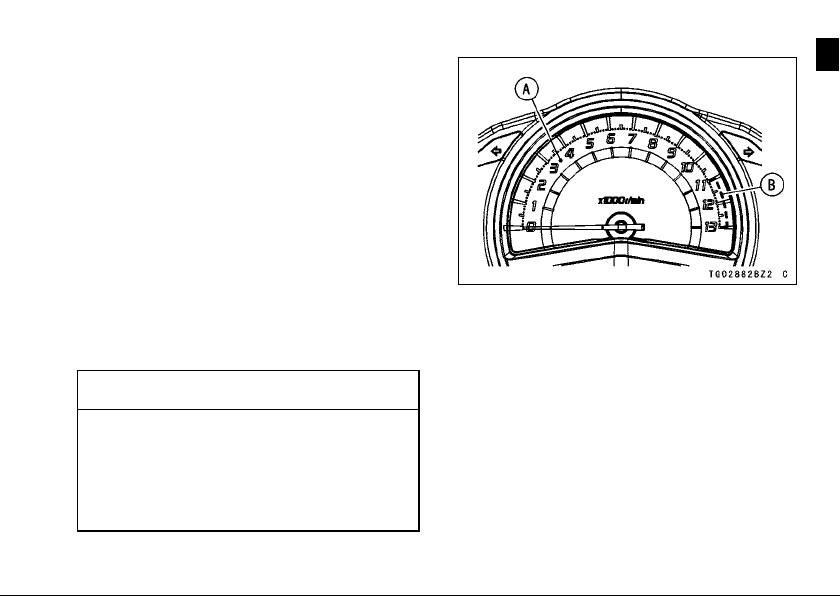
Tachometer
The tachometer shows the engine
speed in revolutions per m in ute (r/min,
rpm). On the right side of the tachome-
ter face is a portion called th e “red
zone”. Engine r/ min (rpm) in the
red zone is above maximum recom-
mended engine speed and is also
above the range for good performance.
NOTICE
Engine r/min (rpm) should not
be allowed to enter the red zone;
operation in the red zone will
overstress the engine and may
cause serious engine damage.
A. Tachometer
B. Red Zone
When the ignition key is turned to
“ON”, the tachometer needle momen-
tarily goes from the minimum to the
maximum, then goes back from the
maximum to the minimum reading to
check its operation. If the tachome-
ter does not operate correctly, have
it checked by an authorized Kawasaki
dealer.
22 GENERAL INFORMATION
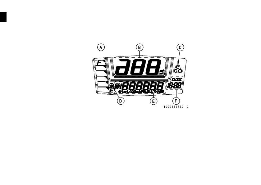
Multifunction Meter
The multifunction meter displays the
following functions.
A. Fuel Gauge
B. Speedometer
C. Economical Riding
Indicator
D. Fuel Level Warning Symbol
E. Multifunction Display
Odometer
Trip meter A
Trip meter B
Current Mileage
Average Mileage
Cruising Range
F. C l o c k
When the ignition key is turned to “ON”, all LCD segments are displayed with
opening display functions for few seconds, then the multifunction meter turns to
operational mode.
GENERAL INFORMATION 23
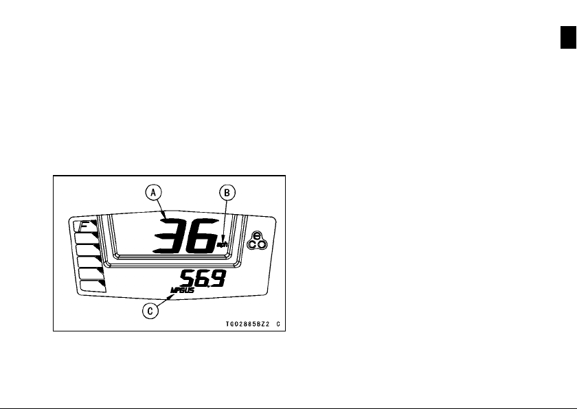
Speedometer -
The speedometer shows the speed
of the vehicle in digital values.
Unit Setting -
The unit setting in the m eter instru-
ment can be changed according to lo-
cal regulations. Make sure the unit set-
ting is correctly displayed before riding.
A. Speedometer
B. Speed Unit
C. Mileage Unit
NOTE
○
Do not operate the motorcycle with
wrong unit (mph or km/h) of the
speedometer.
To change the meter display units in
the meter instrument as follows:
•
Display the od ometer in the multi-
function display. Refer to the Multi-
function Display section.
•
Push the RESET button while push-
ing the MODE button to select the
display units.
L/100km (km/h) → km/L (km/h) →
MPG US (mph) → MP G UK (mph) →
L/100km (km/h)...
•
The display units on the multifunction
meter can be changed depending on
the selected mileage unit as shown.
24 GENERAL INFORMATION
Mileage
Units
Speed Units
Distance
Units
L/100km
km/L
km/h km
MPG US
MPG UK
mph mile
Multifunction Display
The following display modes can be
shifted by pushing the M ODE button.
Odometer → Trip meter A → Trip me-
ter B → Current Mileage → Average
Mileage → Cruis ing Range → Odome-
ter...
NOTE
○
For safety, do not operate the instru-
ment bu ttons while riding the motor-
cycle.
○
The multifunction display is dis-
played in the unit depending on the
unit mode setting, refer to the “Unit
Setting” item in this sec tio n.
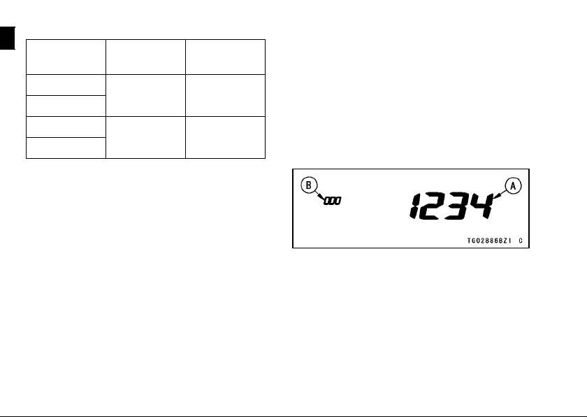
Odometer -
The odometer shows the total dis-
tance in kilometers or miles that the ve-
hicle has been ridden. This meter can-
not be reset.
A. Odometer
B. “ODO”
NOTE
○
The data is maintained even if the
battery is disconnected.
○
When the figures come to 999999,
they are stopped and locked.
GENERAL INFORMATION 25
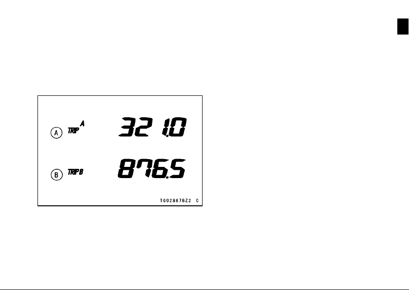
Tri p Meter -
The trip meters show the distance in
kilometers (miles) traveled since they
were last reset to zero.
TRIP A: 0.0 ∼ 9999.9
TRIP B: 0.0 ∼ 9999.9
A. Trip A
B. Trip B
To r e se t th e tr i p m e t er :
•
PushtheMODEbuttontodisplaythe
trip meter A or B.
•
Push the RESET button and hold it
in.
•
After two seconds, the figure display
turns to 0.0, and then starts cou nting
when the vehicle is operated. The
meter counts until it is reset.
NOTE
○
The data is maintained by the back
-up power if the ignition key is turned
off.
○
When the trip meter reaches 9999.9
while running, the m eters reset to 0.0
and continues counting.
○
When the battery is disconnected,
the meter display resets to 0.0.
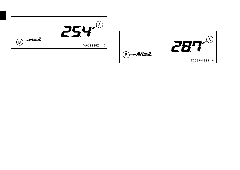
Current Mileage -
This display mode shows the current
mileage by numerical value. The cur-
rent mileage display is renewed every
4 seconds.
26 GENERAL INFORMATION
A. Current Mileage
B. “km/L”
NOTE
○
The display unit modes can be
changed, refer to the “Unit Setting”
item in this section.
○
Thenumericalvalueshows“––.–”
until 4 seconds have passed and the
speedometer is rises to above 5 km/h
(3 mph).
Average Mileage -
This display mode shows the av-
erage mileage by numerical value
counted from the start of measuring
to present time. The average mileage
display is renewed every 4 ∼ 6sec-
onds.
A. Average Mileage
B. “AV km/L”
•
While the average mileag e is dis-
played, push the R ESET button and
hold it in until the average mileage
values resets to “– –. –”.
NOTE
○
The display un it modes can be
changed, refer to the “Unit Setting”
item in this section.
○
After resetting the average mileage,
the numerical value is not displayed
until 5 mL (0.2 US oz.) of fuel has
GENERAL INFORMATION 27
been used and 100 m (328 ft) has
been traveled.
○
The data is maintained by back up
power if the ignition switch is turned
“OFF”.
○
When the battery is disconnected,
the data resets to “– –.–”.
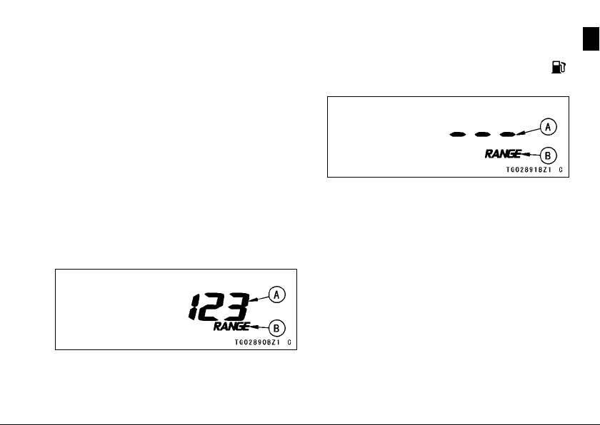
Cruising Range -
This display shows the cruising range
by numerical value and indicates the
cruising range from the remaining fuel
in the fuel tank. This cruising range
display is renewed every 20 seconds.
A. Cruising Range
B. "RANGE"
The cruising range value displays "-
- -" when the fuel warning symbol (
)
blinks in the multifunction meter.
A."---"display
B. "RANGE"
NOTE
○
The display unit modes can be
changed, refer to the “Unit Setting”
in this section.
○
The display range for cruising range
is 0 ~ 999.
○
The cruising range value may not
indicate the actual value. Use this
value for your reference only.
28 GENERAL INFORMATION
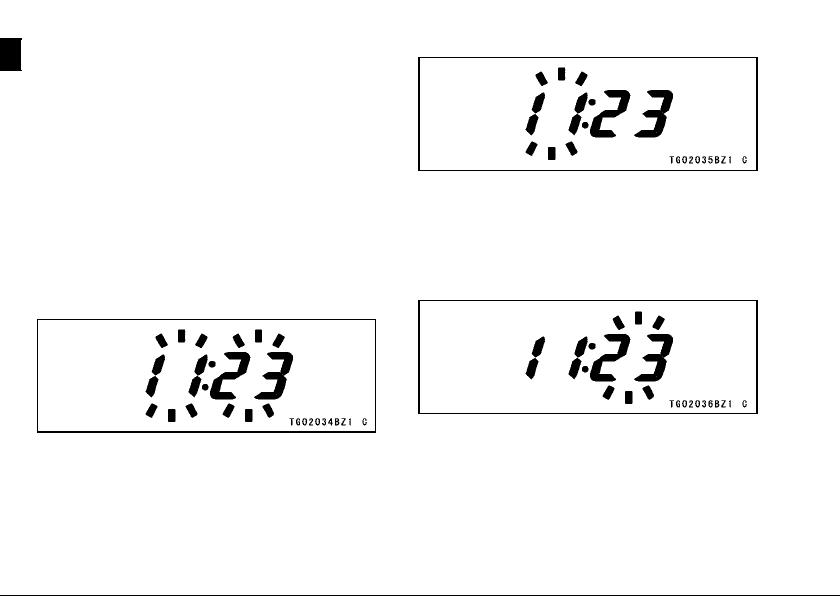
Clock -
To adjust hours and minutes, do the
followings while the motorcycle is a t a
stop.
•
Turn the ignition switch to “ON”.
•
Display the odometer in the multi-
function dis pla y. Refer to the “Multi-
function Displa y” item in this section.
•
Push the RESET button for more
than 2 seconds. Both the hour and
minute displays start blinking.
•
Push the RESET button. The hour
display only b links. Push the MO DE
button to advance the hours.
•
Push the RESET button. The hour
display stops blinking and the minute
display starts blin king. Push the
MODE button to advance the min-
utes.
•
Push the RESET button. Both the
hour and minute displays start blink-
ing again.
•
Push the MODE button. The dis-
plays stop blinking and the clock
starts working.
GENERAL INFORMATION 29
NOTE
○
Pushing the MODE button momen-
tarily advances the hour or minute
step by step. Pushing and hold-
ing the button advances the hour or
minute continuously.
○
The clock works n ormally by the back
-up power while the ignition switch is
turned “OFF”.
○
When the battery is disconnected,
theclockisresetto1:00andstarts
working again when the battery is
connected.
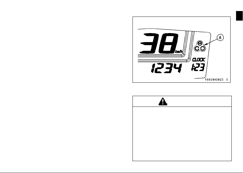
Economical Riding Indicator -
When the operator is driving the mo-
torcycle for optimum fuel-efficiency, the
economical riding indicator appears on
the multifunction meter to indicate fa-
vorable fuel consumption. Monitoring
the economical riding indicator can
help the rider maximize fuel efficiency.
A. Economical Riding Indicator
WARNING
Failing to properly observe the
road ahead increases the chance
of an accident resulting in se-
vere injury or death. Do not con-
centrate on the economical rid-
ing indicator by taking your eyes
off the road; observe using pe-
ripheral vision.
Loading...