


MX-GB5
SERVICE MANUAL
COPYRIGHT © 2004 VICTOR COMPANY OF JAPAN, LIMITED
No.MB160
2004/5
COMPACT COMPONENT SYSTEM
MB16020045
MX-GB6, MX-GB5
TABLE OF CONTENTS
1 PRECAUTION. . . . . . . . . . . . . . . . . . . . . . . . . . . . . . . . . . . . . . . . . . . . . . . . . . . . . . . . . . . . . . . . . . . . . . . . . 1-4
2 SPECIFIC SERVICE INSTRUCTIONS . . . . . . . . . . . . . . . . . . . . . . . . . . . . . . . . . . . . . . . . . . . . . . . . . . . . . . 1-7
3 DISASSEMBLY . . . . . . . . . . . . . . . . . . . . . . . . . . . . . . . . . . . . . . . . . . . . . . . . . . . . . . . . . . . . . . . . . . . . . . . 1-8
4 ADJUSTMENT . . . . . . . . . . . . . . . . . . . . . . . . . . . . . . . . . . . . . . . . . . . . . . . . . . . . . . . . . . . . . . . . . . . . . . . 1-31
5 TROUBLESHOOTING . . . . . . . . . . . . . . . . . . . . . . . . . . . . . . . . . . . . . . . . . . . . . . . . . . . . . . . . . . . . . . . . . 1-36
SP-MXGB6 SP-MXGB6
SP-MXGB5 SP-MXGB5
CA-MXGB6
CA-MXGB5
J ----------------------------- U.S.A.
C -------------------------- Canada
Area suffix
1-2 (No.MB160)
SPECIFICATION
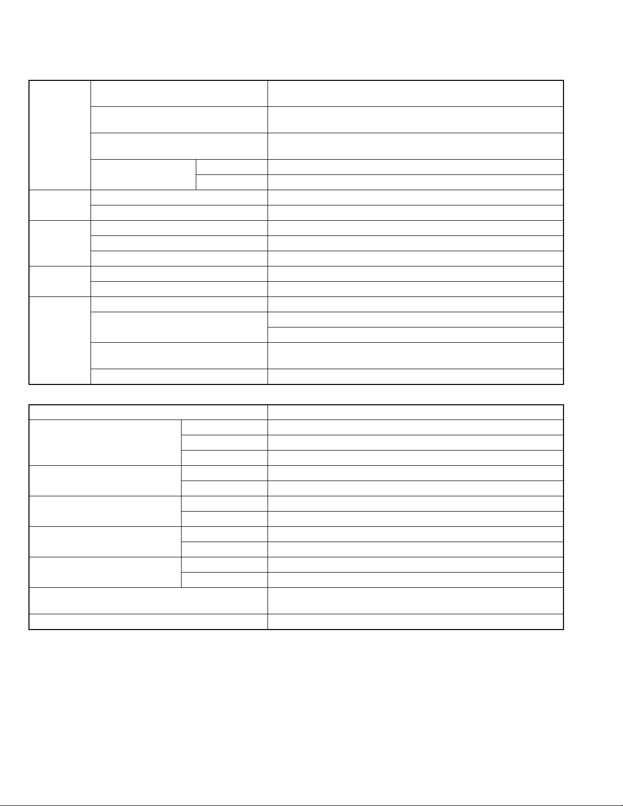
Amplifier section-CA-MXGB6
Speaker section-SP-MXGB6
Design and specifications are subject to change without notice.
Output Power SUBWOOFERS 170 W per channel, min. RMS, driven into 6 Ω at 63 Hz with no more than
10% total harmonic distortion.
MAIN SPEAKERS 80 W per channel, min. RMS, driven into 4 Ω at 1 kHz with no more than
10% total harmonic distortion.
Audio input sensitivity/Impedance
(at 1 kHz, measured at MAIN SPEAKERS)
AUX:400 mV/50 kΩ
Speakers/Impedance Subwoofers 6 Ω - 16 Ω
Main speakers 4 Ω - 8 Ω
Tuner FM tuning range 87.50 MHz - 108.00 MHz
AM tuning range 530 kHz - 1 710 kHz
CD player CD Capacity 3 CDs
Dynamic range 85 dB
Signal-to-noise ratio 85 dB
Cassette deck Frequency response Normal (type I) 50 Hz - 14 000 Hz
Wow and flutter 0.15% (WRMS)
General Power requirement AC 120 V , 60 Hz
Power consumption 230 W (at operation)
23.8 W (on standby)
Dimensions (approx.) 270 mm × 317 mm × 480 mm (W/H/D)
(10 11/16 in. × 12 1/2 in. × 18 15/16 in.)
Mass (approx.) 10.5 kg (23.2 lbs)
Type 3-way bass-reflex type
Speaker units Subwoofer 20 cm (7 7/8 in.) cone × 1
Main Woofer 12 cm (4 3/4 in.) cone × 1
Tweeter 5 cm (2 in.) cone × 1
Power handling capacity Subwoofer 170 W
Main speaker 80 W
Impedance Subwoofer 6 Ω
Main speaker 4 Ω
Frequency range Subwoofer 25 Hz - 100 Hz
Main speaker 100 Hz - 20 000 Hz
Sound pressure level Subwoofer 75 dB/W·m
Main speaker 82 dB/W·m
Dimensions (approx.) 233 mm × 456 mm × 360 mm (W/H/D)
(9 3/16 in. × 18 in. × 14 3/16 in.)
Mass (approx.) 6.6 kg (14.6 lbs) each
(No.MB160)1-3
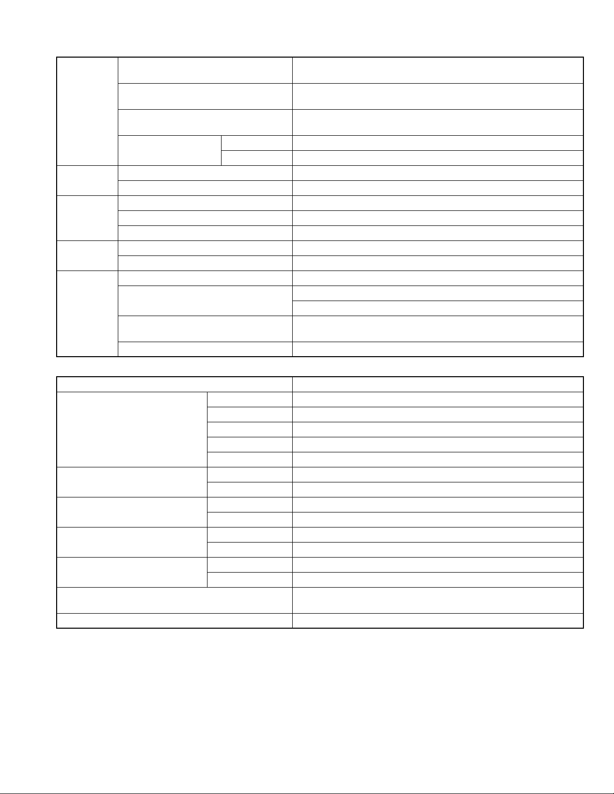
Amplifier section-CA-MXGB5
Speaker section-SP-MXGB5
Design and specifications are subject to change without notice.
Output Power SUBWOOFERS 160 W per channel, min. RMS, driven into 6 Ω at 63 Hz with no more than
10% total harmonic distortion.
MAIN SPEAKERS 70 W per channel, min. RMS, driven into 4 Ω at 1 kHz with no more than
10% total harmonic distortion.
Audio input sensitivity/Impedance
(at 1 kHz, measured at MAIN SPEAKERS)
AUX:400 mV/50 kΩ
Speakers/Impedance Subwoofers 6 Ω - 16 Ω
Main speakers 4 Ω - 8 Ω
Tuner FM tuning range 87.50 MHz - 108.00 MHz
AM tuning range 530 kHz - 1 710 kHz
CD player CD Capacity 3 CDs
Dynamic range 85 dB
Signal-to-noise ratio 85 dB
Cassette deck Frequency response Normal (type I) 50 Hz - 14 000 Hz
Wow and flutter 0.15% (WRMS)
General Power requirement AC 120 V , 60 Hz
Power consumption 220 W (at operation)
23.3 W (on standby)
Dimensions (approx.) 270 mm × 317 mm × 480 mm (W/H/D)
(10 11/16 in. × 12 1/2 in. × 18 15/16 in.)
Mass (approx.) 10 kg (22.1 lbs)
Type 4-way bass-reflex type
Speaker units Subwoofer 16 cm (6 5/16 in.) cone × 1
Main Woofer 16 cm (6 5/16 in.) cone × 1
Tweeter 2 cm (13/16 in.) dome × 1
Midrange 5 cm (2 in.) cone × 1
Tweeter 2 cm (13/16 in.) dome × 1
Power handling capacity Subwoofer 160 W
Main speaker 70 W
Impedance Subwoofer 6 Ω
Main speaker 4 Ω
Frequency range Subwoofer 25 Hz - 90 Hz
Main speaker 90 Hz - 20 000 Hz
Sound pressure level Subwoofer 75 dB/W·m
Main speaker 86 dB/W·m
Dimensions (approx.) 302.5 mm × 325.5 mm × 345 mm (W/H/D)
(11 15/16 in. × 12 7/8 in. × 13 5/8 in.)
Mass (approx.) 6.6 kg (14.6 lbs) each
1-4 (No.MB160)
SECTION 1
PRECAUTION
1.1 Safety Precautions
(1) This design of this product contains special hardware and
many circuits and components specially for safety purpos-
es. For continued protection, no changes should be made
to the original design unless authorized in writing by the
manufacturer. Replacement parts must be identical to
those used in the original circuits. Services should be per-
formed by qualified personnel only.
(2) Alterations of the design or circuitry of the product should
not be made. Any design alterations of the product should
not be made. Any design alterations or additions will void
the manufacturers warranty and will further relieve the
manufacture of responsibility for personal injury or property
damage resulting therefrom.
(3) Many electrical and mechanical parts in the products have
special safety-related characteristics. These characteris-
tics are often not evident from visual inspection nor can the
protection afforded by them necessarily be obtained by us-
ing replacement components rated for higher voltage, watt-
age, etc. Replacement parts which have these special
safety characteristics are identified in the Parts List of Ser-
vice Manual. Electrical components having such features
are identified by shading on the schematics and by ( ) on
the Parts List in the Service Manual. The use of a substitute
replacement which does not have the same safety charac-
teristics as the recommended replacement parts shown in
the Parts List of Service Manual may create shock, fire, or
other hazards.
(4) The leads in the products are routed and dressed with ties,
clamps, tubings, barriers and the like to be separated from
live parts, high temperature parts, moving parts and/or
sharp edges for the prevention of electric shock and fire
hazard. When service is required, the original lead routing
and dress should be observed, and it should be confirmed
that they have been returned to normal, after reassem-
bling.
(5) Leakage shock hazard testing
After reassembling the product, always perform an isola-
tion check on the exposed metal parts of the product (an-
tenna terminals, knobs, metal cabinet, screw heads,
headphone jack, control shafts, etc.) to be sure the product
is safe to operate without danger of electrical shock.Do not
use a line isolation transformer during this check.
• Plug the AC line cord directly into the AC outlet. Using a
"Leakage Current Tester", measure the leakage current
from each exposed metal parts of the cabinet, particular-
ly any exposed metal part having a return path to the
chassis, to a known good earth ground. Any leakage cur-
rent must not exceed 0.5mA AC (r.m.s.).
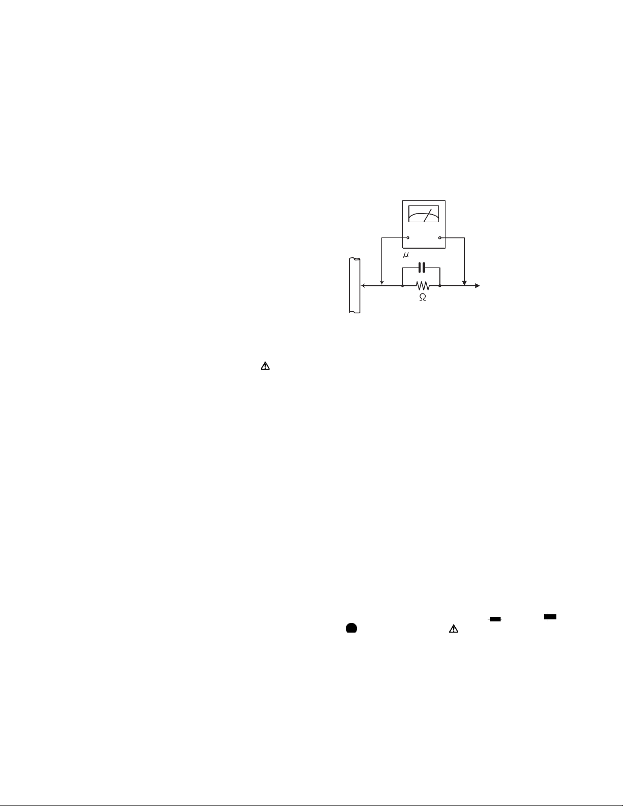
• Alternate check method
Plug the AC line cord directly into the AC outlet. Use an
AC voltmeter having, 1,000
Ω per volt or more sensitivity
in the following manner. Connect a 1,500
Ω 10W resistor
paralleled by a 0.15
µF AC-type capacitor between an
exposed metal part and a known good earth ground.
Measure the AC voltage across the resistor with the AC
voltmeter.
Move the resistor connection to each exposed metal
part, particularly any exposed metal part having a return
path to the chassis, and measure the AC voltage across
the resistor. Now, reverse the plug in the AC outlet and
repeat each measurement. Voltage measured any must
not exceed 0.75 V AC (r.m.s.). This corresponds to 0.5
mA AC (r.m.s.).
1.2 Warning
(1) This equipment has been designed and manufactured to
meet international safety standards.
(2) It is the legal responsibility of the repairer to ensure that
these safety standards are maintained.
(3) Repairs must be made in accordance with the relevant
safety standards.
(4) It is essential that safety critical components are replaced
by approved parts.
(5) If mains voltage selector is provided, check setting for local
voltage.
1.3 Caution
Burrs formed during molding may be left over on some parts
of the chassis.
Therefore, pay attention to such burrs in the case of pre-
forming repair of this system.
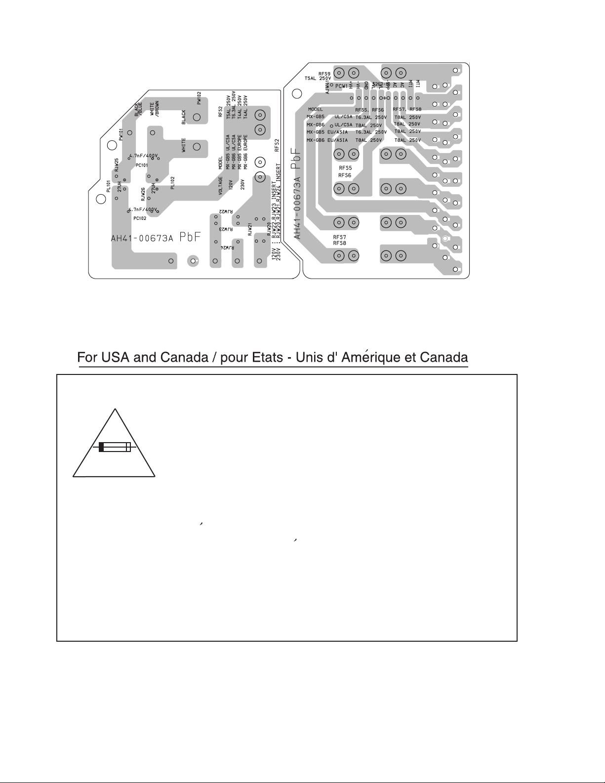
1.4 Critical parts for safety
In regard with component parts appearing on the silk-screen
printed side (parts side) of the PWB diagrams, the parts that are
printed over with black such as the resistor ( ), diode ( )
and ICP ( ) or identified by the " " mark nearby are critical
for safety. When replacing them, be sure to use the parts of the
same type and rating as specified by the manufacturer.
(This regulation dose not Except the J and C version)
Good earth ground
Place this
probe on
each exposed
metal part.
AC VOLTMETER
(Having 1000
ohms/volts,
or more sensitivity)
1500 10W
0.15 F AC TYPE
(No.MB160)1-5
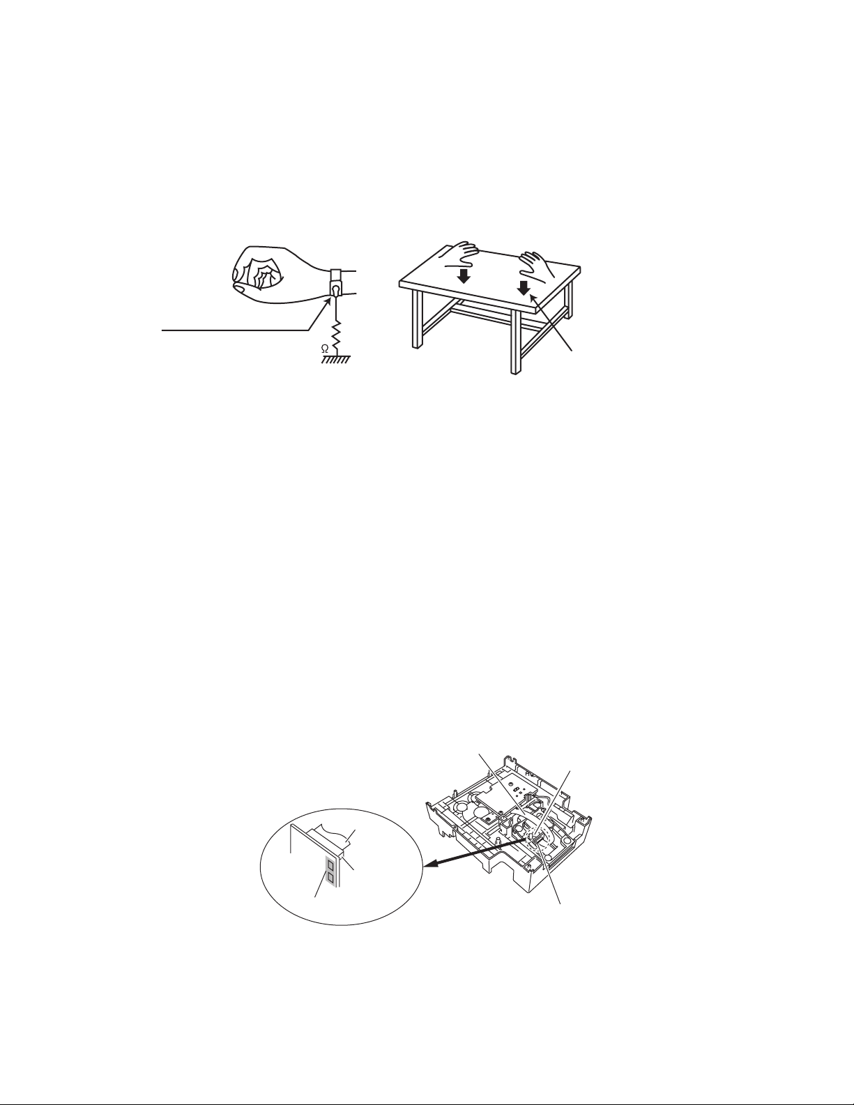
1.5 Preventing static electricity
Electrostatic discharge (ESD), which occurs when static electricity stored in the body, fabric, etc. is discharged, can destroy the laser
diode in the traverse unit (optical pickup). Take care to prevent this when performing repairs.
1.5.1 Grounding to prevent damage by static electricity
Static electricity in the work area can destroy the optical pickup (laser diode) in devices such as laser products.
Be careful to use proper grounding in the area where repairs are being performed.
(1) Ground the workbench
Ground the workbench by laying conductive material (such as a conductive sheet) or an iron plate over it before placing the
traverse unit (optical pickup) on it.
(2) Ground yourself
Use an anti-static wrist strap to release any static electricity built up in your body.
(3) Handling the optical pickup
• In order to maintain quality during transport and before installation, both sides of the laser diode on the replacement optical
pickup are shorted. After replacement, return the shorted parts to their original condition.
(Refer to the text.)
• Do not use a tester to check the condition of the laser diode in the optical pickup. The tester's internal power source can easily
destroy the laser diode.
1.6 Handling the traverse unit (optical pickup)
(1) Do not subject the traverse unit (optical pickup) to strong shocks, as it is a sensitive, complex unit.
(2) Cut off the shorted part of the flexible cable using nippers, etc. after replacing the optical pickup. For specific details, refer to the
replacement procedure in the text. Remove the anti-static pin when replacing the traverse unit. Be careful not to take too long a
time when attaching it to the connector.
(3) Handle the flexible cable carefully as it may break when subjected to strong force.
(4) I t is not possible to adjust the semi-fixed resistor that adjusts the laser power. Do not turn it.
1.7 Attention when traverse unit is decomposed
*Please refer to "Disassembly method" in the text for the pickup unit.
• Apply solder to the short land sections before the flexible wire is disconnected from the connecto on the servo board. (If the flexible
wire is disconnected without applying solder, the pickup may be destroyed by static electricity.)
• In the assembly, be sure to remove solder from the short land sections after connecting the flexible wire.
1M
Conductive material
(conductive sheet) or iron palate
(caption)
Anti-static wrist strap
Pickup unit connecto
r
Card wire
Pickup unit
connector
Short land section
Card wire
Pickup
1-6 (No.MB160)
1.8 Importance administering point on the safety
Caution: For continued protection against risk of
fire, replace only with same type 5 A/250 V[GB5]
(6.3 A/250 V[GB6]) for RFS2, 6.3 A/250 V[GB5]
(8 A/250 V[GB6]) for RFS5 and RFS6, 8 A/250 V
for RFS7 and RFS8, 5 A/250 V for RFS9.
This symbol specifies type of fast operating fuse.
Precaution: Pour eviter risques de feux, remplacez
le fusible de surete de RFS2 comme le meme type
que 5 A/250 V[GB5](6.3 A/250 V[GB6]),
6,3 A/250 V[GB5](8 A/250 V[GB6]) pour RFS5 et
RFS6, 8 A/250 V pour RFS7 et RFS8, et
5 A/250 V pour RFS9.
Ce sont des fusibles suretes qui functionnes rapide.
^

(No.MB160)1-7
SECTION 2
SPECIFIC SERVICE INSTRUCTIONS
This service manual does not describe SPECIFIC SERVICE INSTRUCTIONS.
1-8 (No.MB160)
SECTION 3
DISASSEMBLY
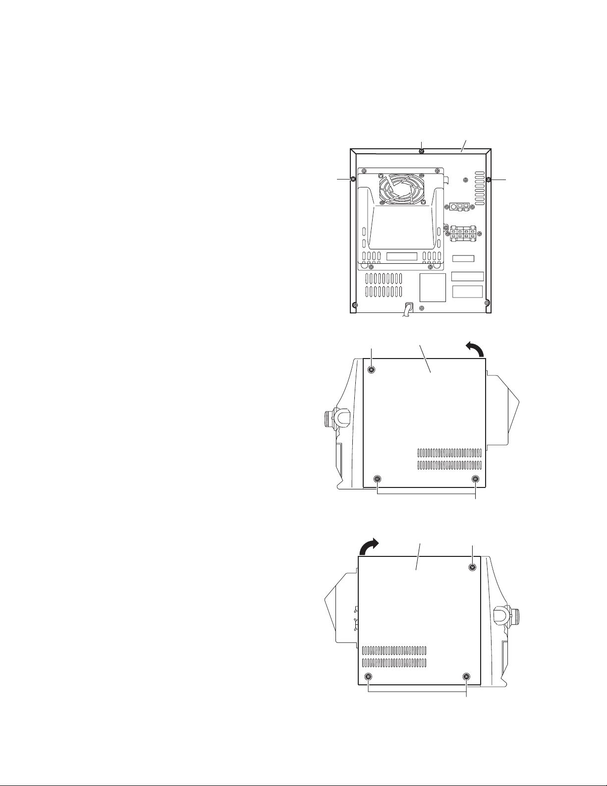
3.1 Main body section
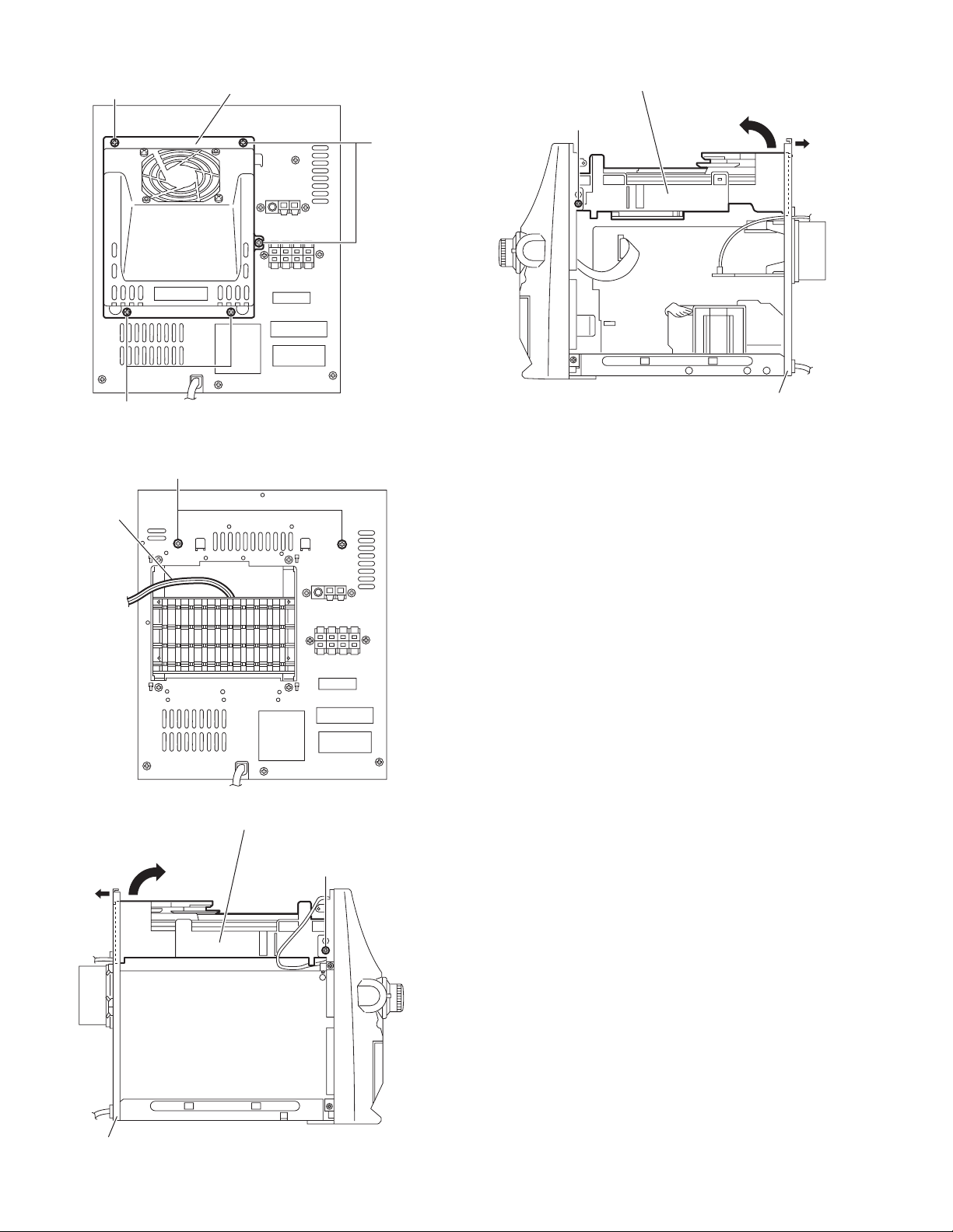
3.1.1 Removing the top cabinet
(See Figs.1 to 3)
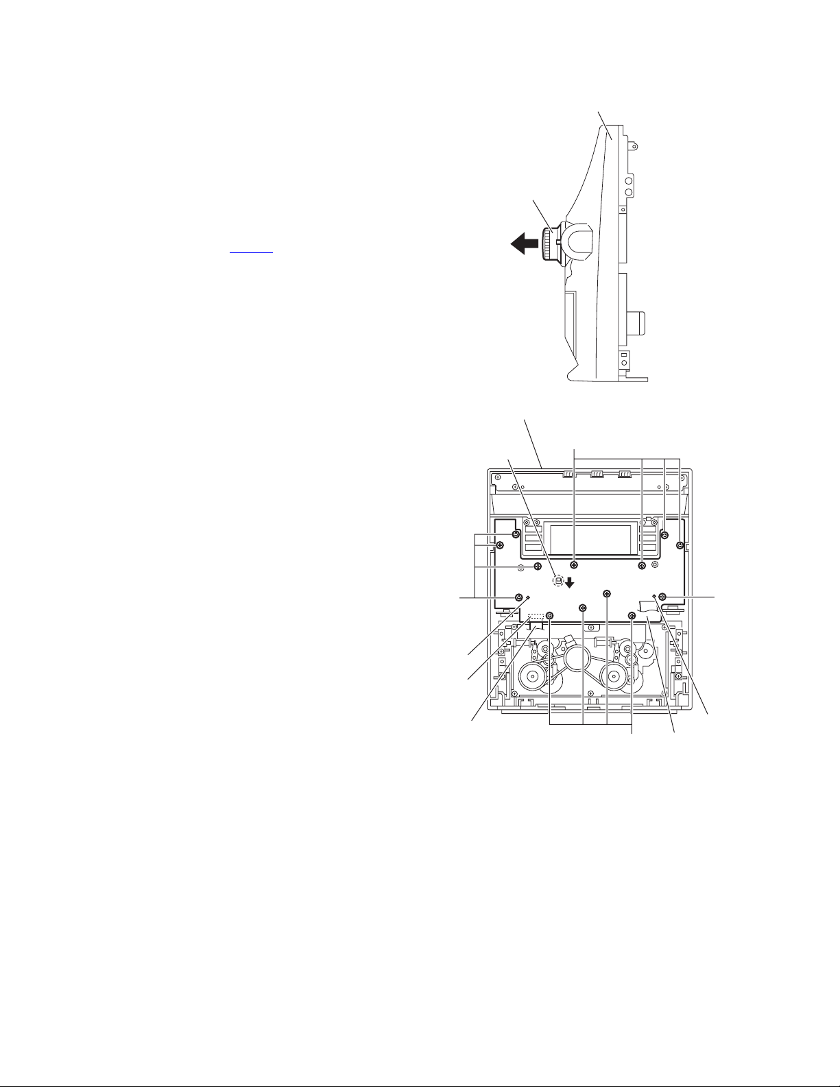
(1) From the back side of the main body, remove the three
screws A attaching the top cabinet. (See Fig.1.)
(2) From the both sides of the main body, remove the six
screws B attaching the top cabinet. (See Figs.2 and 3.)
(3) Remove the top cabinet from the main body while lifting the
rear section of the top cabinet in the direction of the arrow.
(See Figs.2 and 3.)
Fig.1
Fig.2
Fig.3
Top cabinet
A
AA
Top cabinet
B
B
Top cabinet
B
B
(No.MB160)1-9
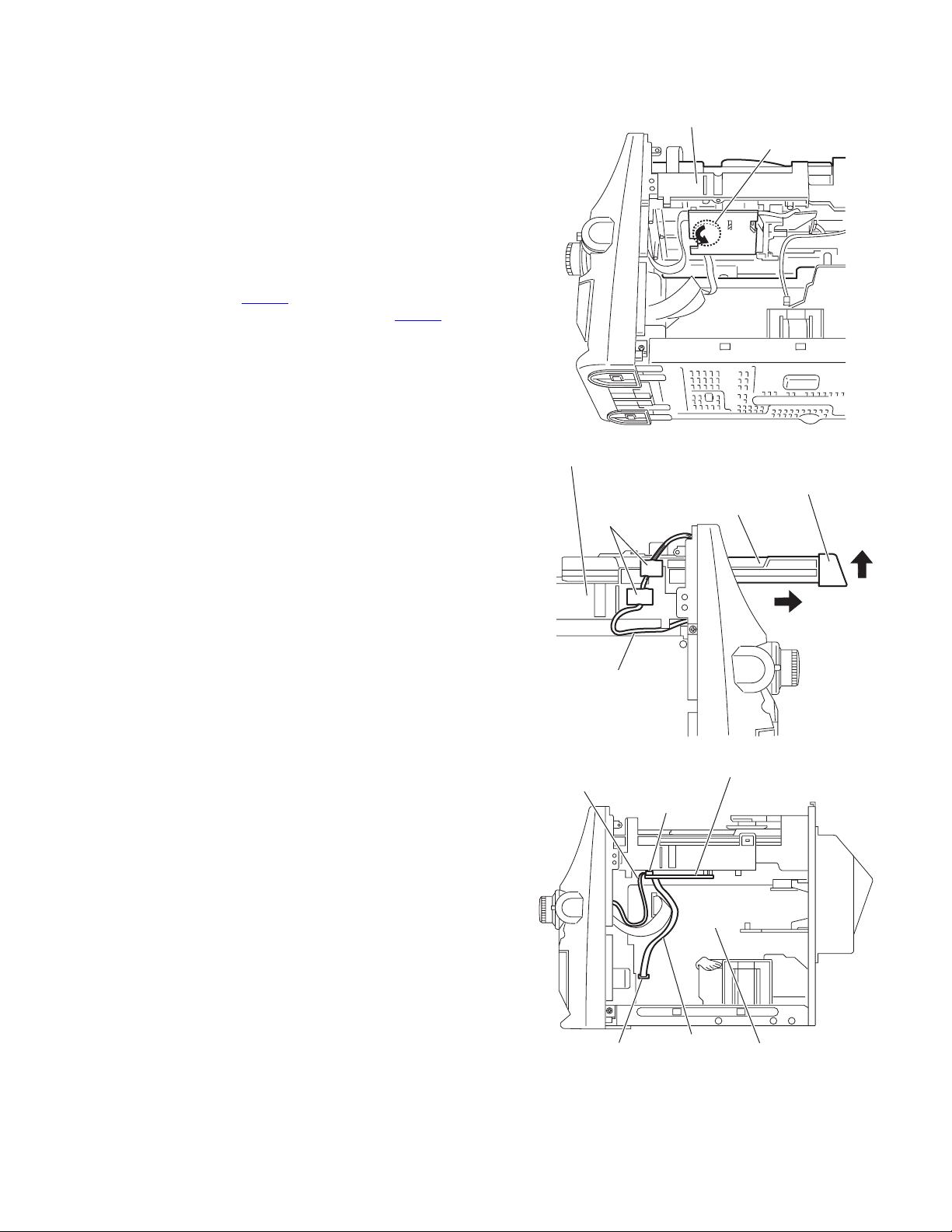
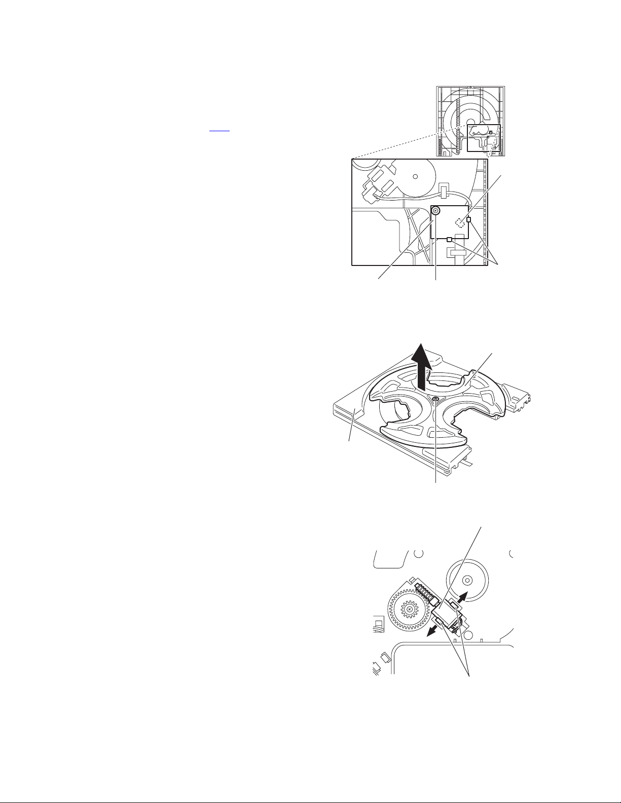
3.1.2 Removing the CD changer mechanism assembly
(See Figs.4 to 10)
• Prior to performing the following procedures, remove the top
cabinet.
(1) From the bottom side of the CD changer mechanism as-
sembly, turn the gear cam in the direction of the arrow and
draw the tray disc out of the CD changer mechanism as-
sembly in the direction of the arrow 1. (See Figs.4 and 5.)
(2) Remove the CD door assembly from the tray disc in the di-
rection of the arrow 2 and push in the tray disc. (See Fig.5.)
(3) From the left side of the main body, remove the spacers fix-
ing the wire. (See Fig.5.)
(4) From the right side of the main body, disconnect the wire
from the connector CW104
on the main board. (See Fig.6.)
(5) Disconnect the card wire from the connector CW105
on the
CD sub board. (See Fig.6.)
(6) From the back side of the main body, remove the five
screws C attaching the heat sink cover. (See Fig.7.)
Reference:
It is not necessary to disconnect the wire of the fan mo-
tor. (See Fig.8.)
(7) Remove the two screws D attaching the CD changer mech-
anism assembly. (See Fig.8.)
(8) From the both sides of the main body, remove the two
screws E attaching the CD changer mechanism assembly.
(See Figs.9 and 10.)
(9) Take out the CD changer mechanism assembly in the di-
rection of the arrow 2 while extending the rear cabinet in
the direction of the arrow 1. (See Figs.9 and 10.)
Fig.4
Fig.5
Fig.6
CD changer mechanism assembly
Gear cam
Tray disc
CD door assembly
CD changer mechanism assembly
Spacers
Wire
1
2
Card wire
Wire
CD sub board
Main board
CW105
CW104
1-10 (No.MB160)
Fig.7
Fig.8
Fig.9
Fig.10
Heat sink cover
C
C
C
Wire
D
CD changer mechanism assembly
Rear cabinet
1
2
E
CD changer mechanism assembly
Rear cabinet
1
2
E
(No.MB160)1-11
3.1.3 Removing the front cabinet assembly
(See Figs.11 to 14)
• Prior to performing the following procedures, remove the top
cabinet and CD changer mechanism assembly.
(1) From the forward side of the main board, disconnect the
card wire from the connector CW101
. (See Fig.11.)
(2) Disconnect the wires from the connectors (CW01A
,
CW108, CW109, CW111, CW112) on the main board.
(See Fig.11.)
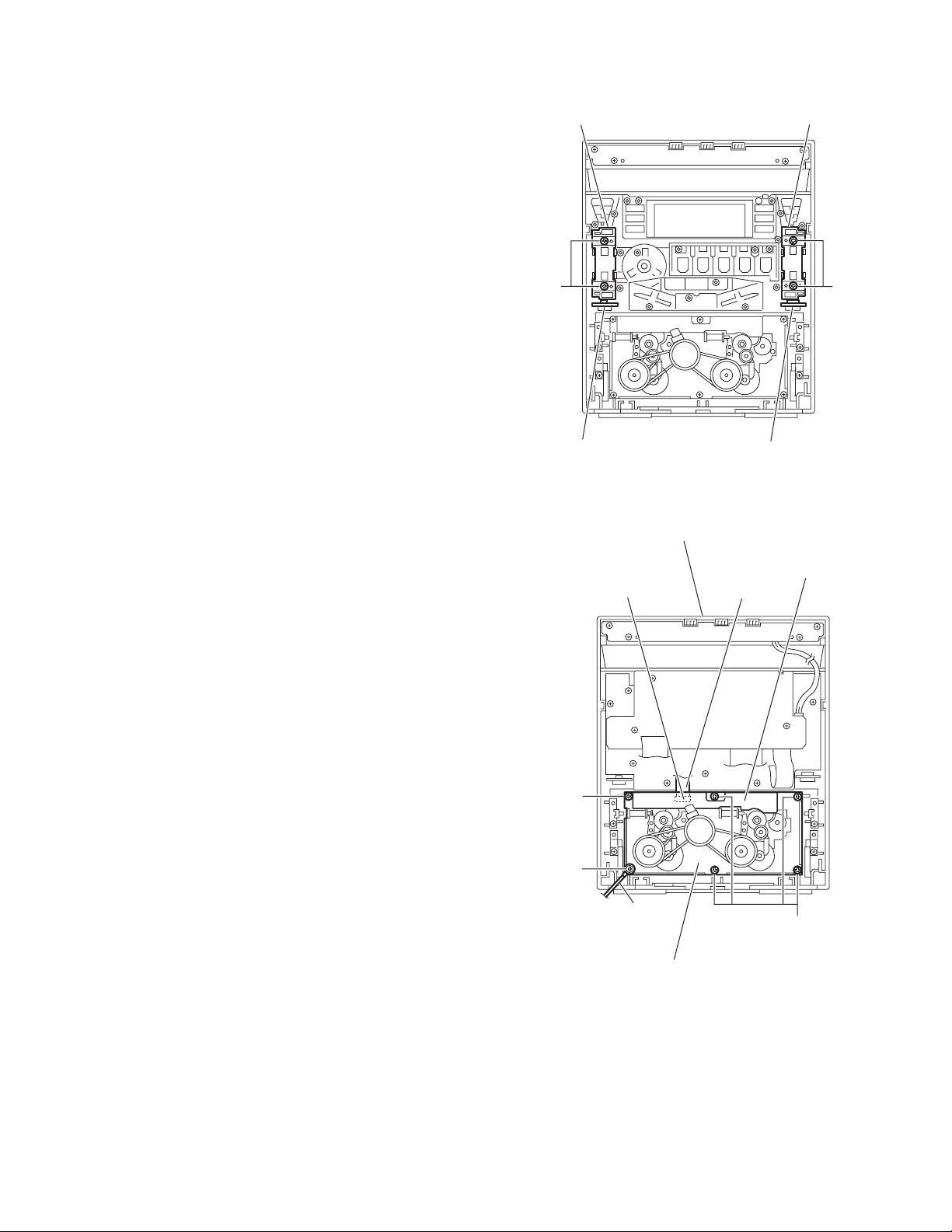
(3) From the top side of the main body, remove the screw F at-
taching the earth wire. (See Fig.12.)
(4) From the both sides of the main body, remove the two
screws G attaching the front cabinet assembly. (See
Figs.12 and 13.)
(5) From the left side of the main body, remove the screw H at-
taching the front cabinet assembly. (See Fig.13.)
(6) From the bottom side of the main body, remove the screw
J attaching the front cabinet assembly. (See Fig.14.)
(7) Release the two joints a and two joints b, remove the front
cabinet assembly in the direction of the arrow. (See Figs.12
to 14.)
Fig.11
Fig.12
Fig.13
Fig.14
Card wire
Wire
Wire
Wire
Wire
Wire
CW101
CW112
CW111
CW108
CW109
Main board
CW01A
Earth wire
Front cabinet assembly
a
G
F
a
Front cabinet assembly
H
G
b
J
Front cabinet assembly
1-12 (No.MB160)
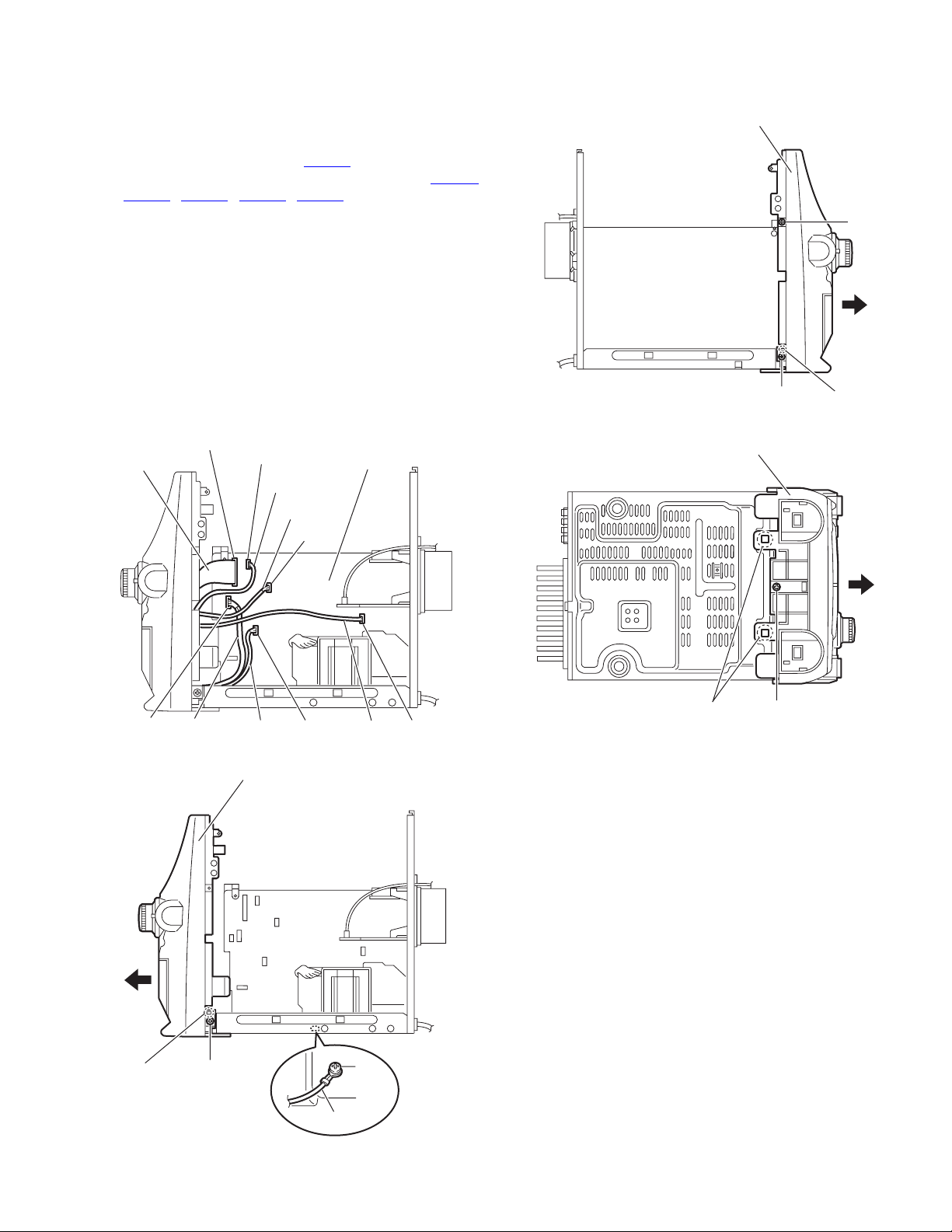
3.1.4 Removing the rear cabinet
(See Figs.15 to 17.)
• Prior to performing the following procedures, remove the top
cabinet.
(1) From the right side of the main body, disconnect the wires
from the connector ACW3
on the amplifier board. (See
Fig.15.)
(2) From the back side of the main body, remove the five
screws K attaching the heat sink cover. (See Fig.16.)
(3) Remove the thirteen screws L attaching the rear cabinet.
(See Fig.17.)
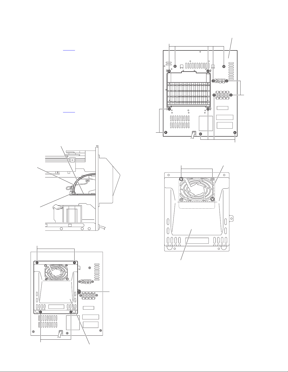
3.1.5 Removing the fan motor
(See Figs.15, 16 and 18)
• Prior to performing the following procedures, remove the top
cabinet.
(1) From the right side of the main body, disconnect the wires
from the connector ACW3
on the amplifier board. (See
Fig.15.)
(2) From the back side of the main body, remove the five
screws K attaching the heat sink cover. (See Fig.16.)
(3) From the back side of the heat sink cover, remove the two
screws M attaching the fan motor. (See Fig.18.)
Fig.15
Fig.16
Fig.17
Fig.18
Amplifier board
Wire
A
CW3
Heat sink cover
K
K
K
Rear cabinet
LL
L
L
L
Heat sink cover
Fan moto
r
M
(No.MB160)1-13
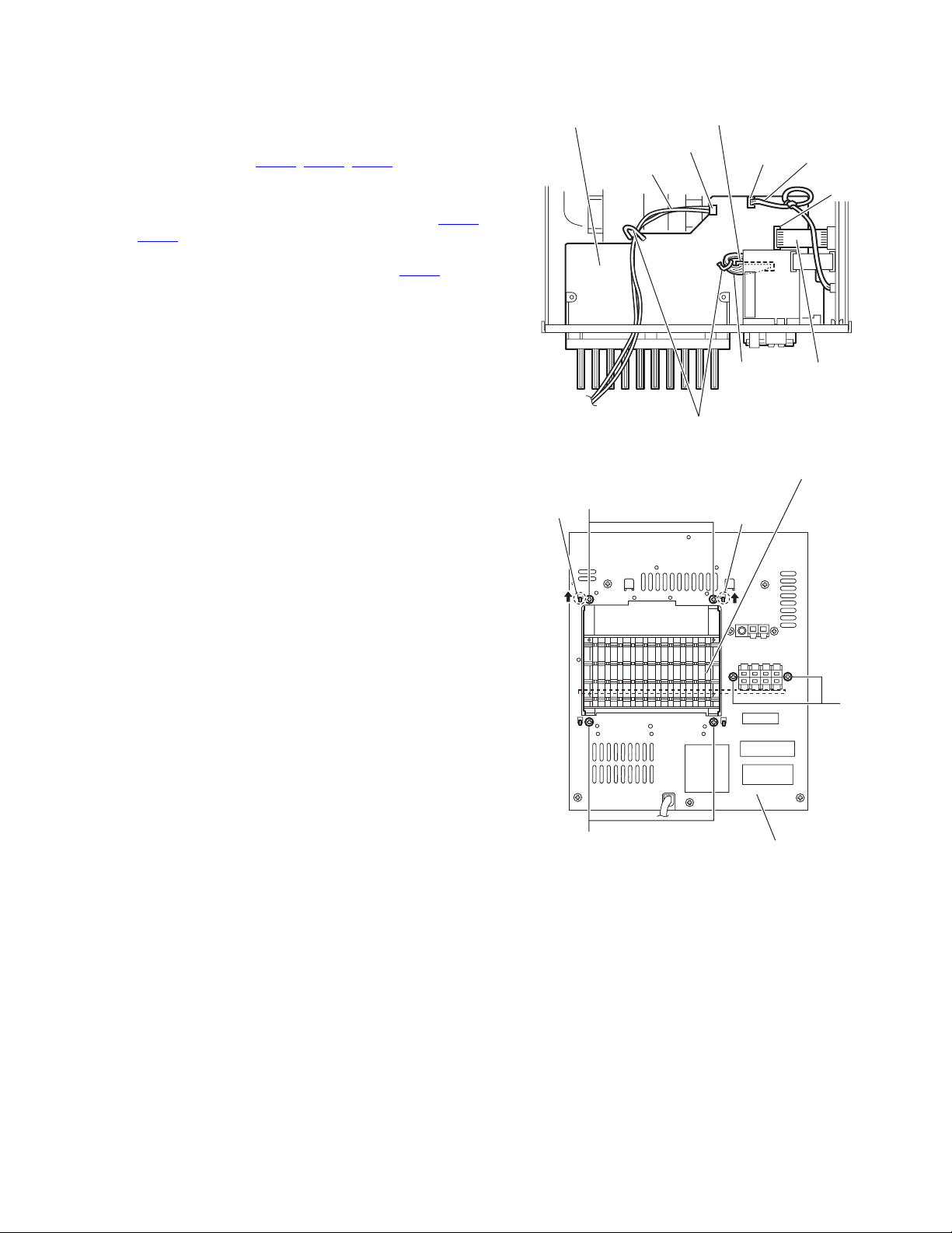
3.1.6 Removing the amplifier board
(See Figs.19 and 20)
• Prior to performing the following procedures, remove the top
cabinet and CD changer mechanism assembly.
(1) From the top side of the main body, disconnect the wires
from the connectors (ACW2
, ACW3, ACW4) on the ampli-
fier board. (See Fig.19.)
Reference:
After connecting the wires to the connectors (ACW2
,
ACW3
), fix the wires with the wire holders as before.
(See Fig.19.)
(2) Disconnect the card wire from the connector ACW1
on the
amplifier board. (See Fig.19.)
(3) From the back side of the main body, remove the six
screws N attaching the amplifier board. (See Fig.20.)
(4) Release the claws (c, d) from the rear cabinet and take out
the amplifier board from the inside of the main body. (See
Fig.20.)
Fig.19
Fig.20
ACW3
ACW4
Wire
Wire
Wire holders
ACW2
ACW1
Amplifier board
Cord wire
Wire
Amplifier board
Rear cabinet
N
N
N
d
c
1-14 (No.MB160)
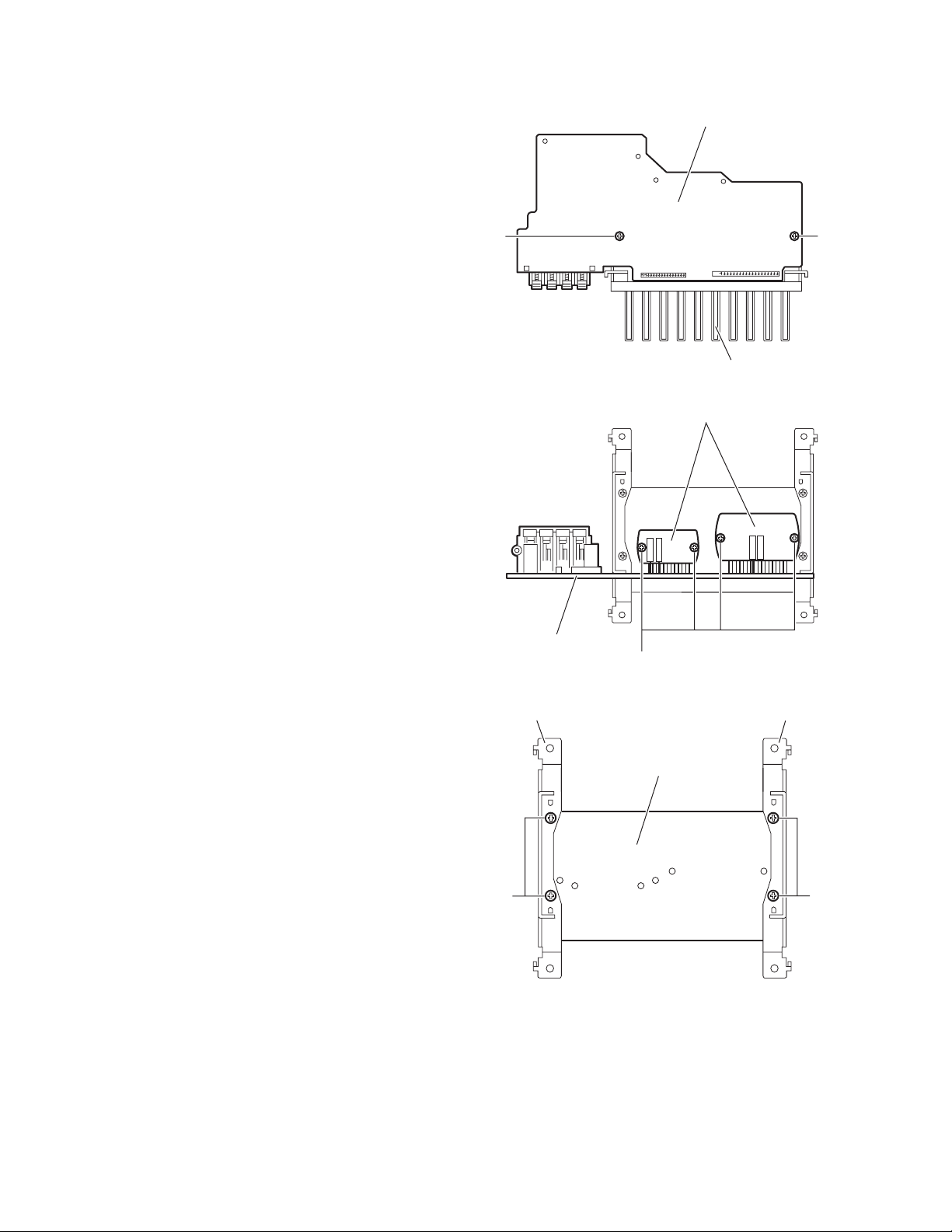
3.1.7 Removing the heat sink
(See Figs.21 to 23)
• Prior to performing the following procedures, remove the top
cabinet, CD changer mechanism assembly and amplifier
board.
(1) From the reverse side of the amplifier board, remove the
two screws P attaching the heat sink. (See Fig.21.)
(2) From the forward side of the amplifier board, remove the
four screws Q attaching the power amplifier IC on the heat
sink. (See Fig.22.)
(3) From the bottom side of the heat sink, remove the four
screws R attaching the brackets on the heat sink. (See
Fig.23.)
Fig.21
Fig.22
Fig.23
Amplifier board
Heat sink
P
P
Q
Amplifier board
Power amplifier IC
R
R
Heat sink
BracketBracket
(No.MB160)1-15
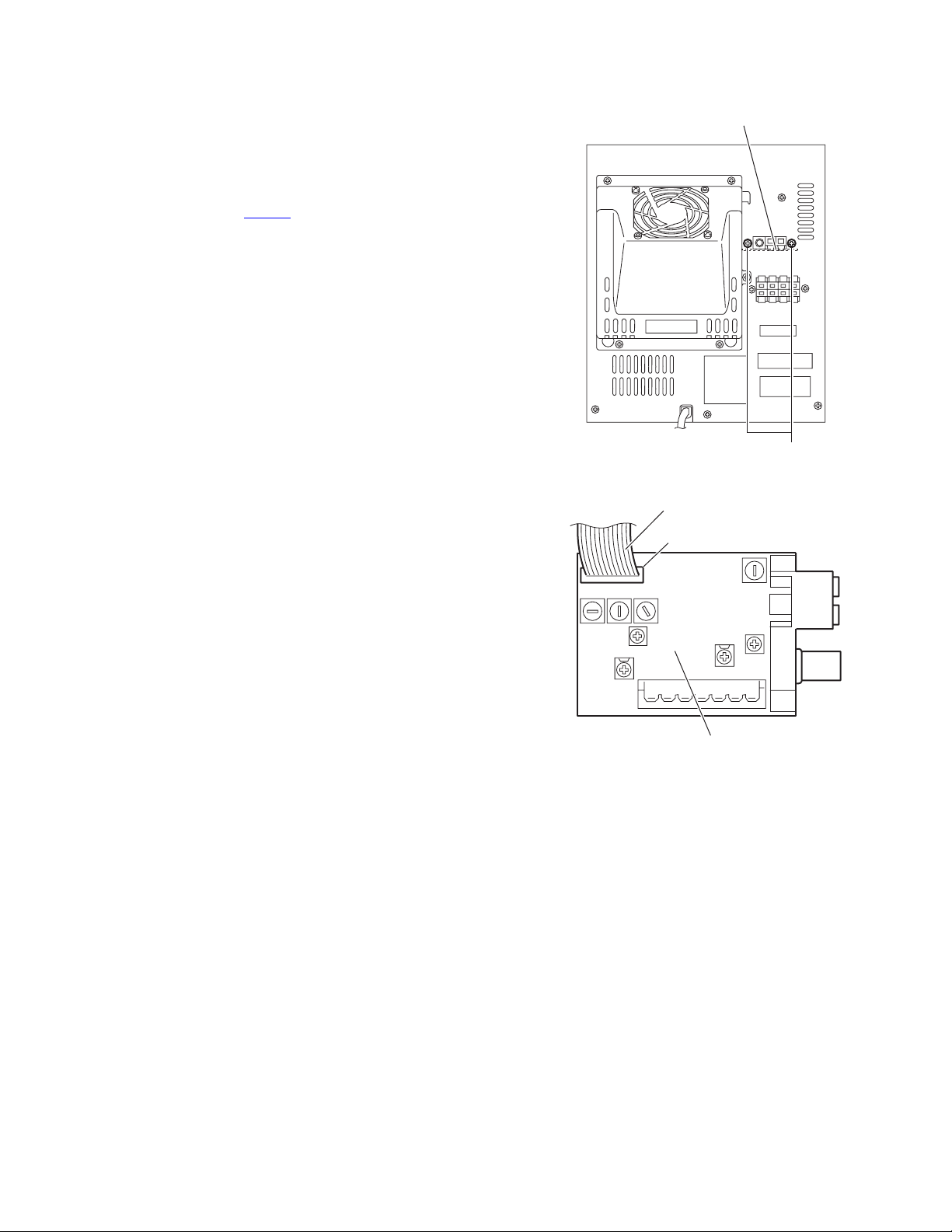
3.1.8 Removing the tuner
(See Figs.24 and 25)
• Prior to performing the following procedures, remove the top
cabinet.
(1) From the back side of the main body, remove the two
screws S attaching the tuner. (See Fig.24.)
(2) From the left side of the main body, take out the tuner.
(3) From the forward side of the tuner, disconnect the card wire
from the connector CON01
. (See Fig.25.)
Fig.24
Fig.25
S
Tuner
CON01
Card wire
Tuner
1-16 (No.MB160)
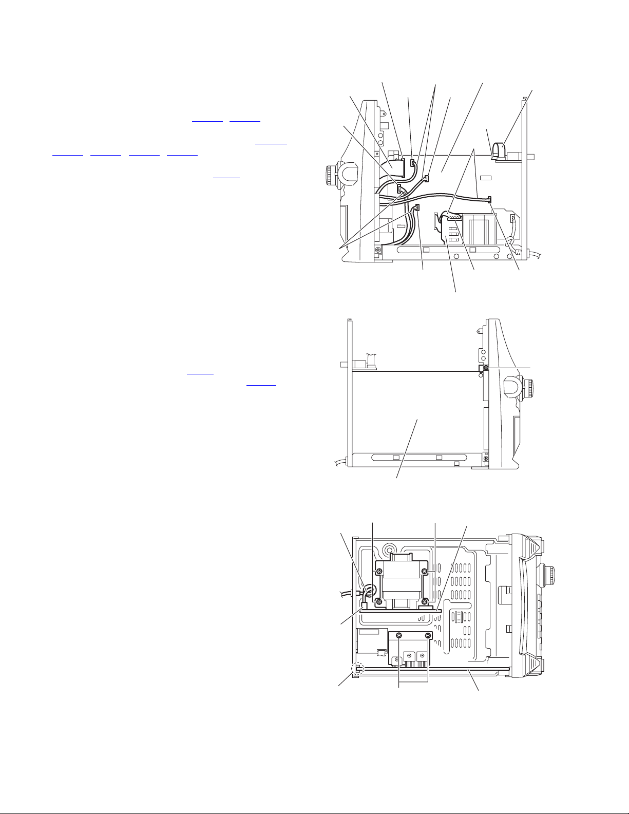
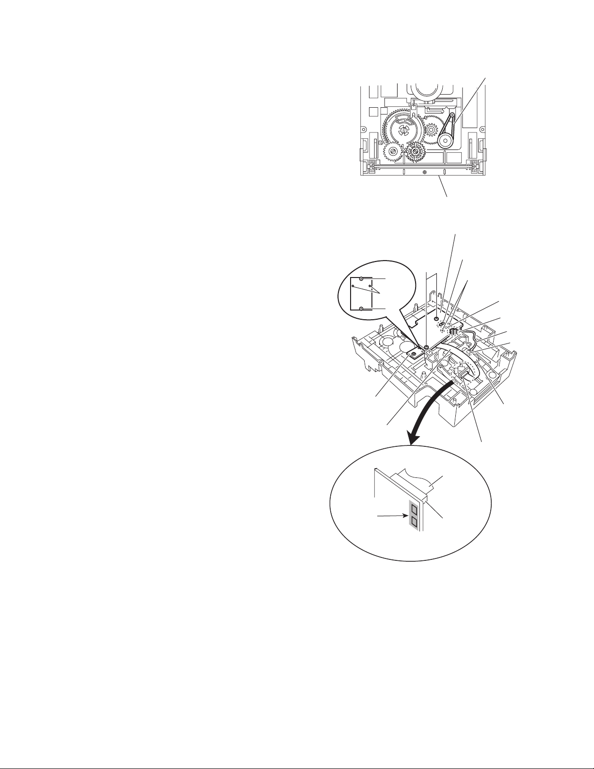
3.1.9 Removing the main board
(See Figs.26 to 28)
• Prior to performing the following procedures, remove the top
cabinet, CD changer mechanism assembly and amplifier
board.
(1) From the forward side of the main board, disconnect the
card wires from the connectors (CW101
, CW102). (See
Fig.26.)
(2) Disconnect the wires from the connectors (CW01A
,
CW108
, CW109, CW111, CW112) on the main board.
(See Fig.26.)
(3) Disconnect the wire from the connector PCW1
on the pow-
er supply board. (See Fig.26.)
(4) From the left side of the main body, remove the screw T at-
taching the main board. (See Fig.27.)
(5) From the top side of the main body, remove the two screws
U attaching the main board. (See Fig.28.)
(6) Take out the main board from the main body.
Reference:
Insert the main board in the slot e before attaching the main
board to the bottom chassis. (See Fig.28.)
3.1.10 Removing the power supply board
(See Figs.26 and 28)
• Prior to performing the following procedures, remove the top
cabinet, CD changer mechanism assembly and amplifier
board.
(1) From the forward side of the power supply board, discon-
nect the wire from the connector PCW1
. (See Fig.26.)
(2) Disconnect the power cord from the connector PW101 on
the power supply board. (See Fig.28.)
(3) From the top side of the main body, remove the four screws
V attaching the power supply board. (See Fig.28.)
(4) Take out the power supply board from the main body.
Fig.26
Fig.27
Fig.28
Card wire
Card wire
Wires
Wires
Wires
Power supply board
PCW1
CW109
CW101
CW01A
CW112
CW108
CW111
CW102
Main board
Main board
T
Power supply board
Power cord
PW101
Main board
e
V
V
U
(No.MB160)1-17
3.1.11 Removing the CD board
(See Fig.29)
• Prior to performing the following procedures, remove the top
cabinet, CD changer mechanism assembly and front cabinet
assembly.
(1) From the inside of the front cabinet assembly, disconnect
the wire from the connector UCW05
on the VFD board.
(2) Remove the four screws W attaching the CD board.
Reference:
When attaching the CD board, align the projections (f, g) of the
front cabinet assembly in the holes of the CD board.
3.1.12 Removing the VFD board
(See Fig.29)
• Prior to performing the following procedures, remove the top
cabinet, CD changer mechanism assembly and front cabinet
assembly.
(1) From the inside of the front cabinet assembly, disconnect
the wire from the connector UCW05
on the VFD board.
(2) Remove the three screws X attaching the VFD board.
(3) Take out the VFD board while releasing the claw h in the
direction of the arrow.
(4) From the forward side of the VFD board, disconnect the
card wire from the connector UCW7
.
Fig.29
f
g
h
CD board
Wier
UCW05
UCW7
Card wire
VFD board
X
W
W
X
1-18 (No.MB160)
3.1.13 Removing the front board
(See Figs.30 and 31)
• Prior to performing the following procedures, remove the top
cabinet, CD changer mechanism assembly, front cabinet as-
sembly and VFD board.
(1) From the outside of the front cabinet assembly, pull out the
volume knob. (See Fig.30.)
(2) From the inside of the front cabinet assembly, remove the
thirteen screws Y attaching the front board. (See Fig.31.)
(3) Take out the front board while releasing the claw i in the di-
rection of the arrow. (See Fig.31.)
(4) From the forward side of the front board, disconnect the
card wire from the connector UCW06
. (See Fig.31.)
Reference:
When attaching the front board, align the projections (j, k) of
the front cabinet assembly in the holes of the front board.
Fig.30
Fig.31
Volume knob
Front cabinet assembly
k
j
i
Front cabinet assembly
UCW06
Cord wire
Front board
Y
Y
Y
Y
(No.MB160)1-19
3.1.14 Removing the AUX IN board
(See Fig.32)
• Prior to performing the following procedures, remove the top
cabinet, CD changer mechanism assembly, front cabinet as-
sembly, VFD board and front board.
(1) From the inside of the front cabinet assembly, remove the
two screws Z attaching the holder.
(2) Take out the AUX IN board from the front cabinet assem-
bly.
3.1.15 Removing the phone board
(See Fig.32)
• Prior to performing the following procedures, remove the top
cabinet, CD changer mechanism assembly, front cabinet as-
sembly, VFD board and front board.
(1) From the inside of the front cabinet assembly, remove the
two screws AA attaching the holder.
(2) Take out the phone board from the front cabinet assembly.
Fig.32
3.1.16 Removing the cassette deck mechanism assembly
(See Fig.33)
• Prior to performing the following procedure, remove the top
cabinet, CD changer mechanism assembly and front cabinet
assembly.
(1) From the inside of the front cabinet assembly, disconnect
the card wire from the connector on the mechanism board.
(2) Remove the five screws AB and screw AB’ attaching the
cassette deck mechanism assembly.
Reference:
When attaching the screw AB’, attach the earth wire with it.
Fig.33
AUX IN board
Phone board
Holder Holder
Z
AA
Front cabinet assembly
Mechanism board
Earth wire
Cassette deck mechanism assembly
Connector
AB
AB
AB'
Card wire
1-20 (No.MB160)
3.2 CD changer mechanism assembly section
• Prior to performing the following procedures, remove the CD changer mechanism assembly. (See "3.1.2 Removing the CD changer
mechanism assembly".)
3.2.1 Removing the tray disc
(See Figs.1 and 2)
(1) Turn the gear cam on the bottom side of the CD changer
mechanism assembly in the direction of the arrow and
draw the tray disc toward the front until it stops. (See Figs.1
and 2.)
(2) Disconnect the card wire from the connector CW103
on the
CD sub board. (See Figs.1 and 2.)
(3) Push down the two tray stoppers and pull out the tray disc.
(See Fig.2.)
Fig.1
Fig.2
Tray disc
CD sub board
Gear cam
CW103
Tray stoppe
r
Tray stopper
CW103
(on the CD sub board)
Tray disc
(No.MB160)1-21
3.2.2 Reinstall the tray disc
(See Figs.3 and 4)
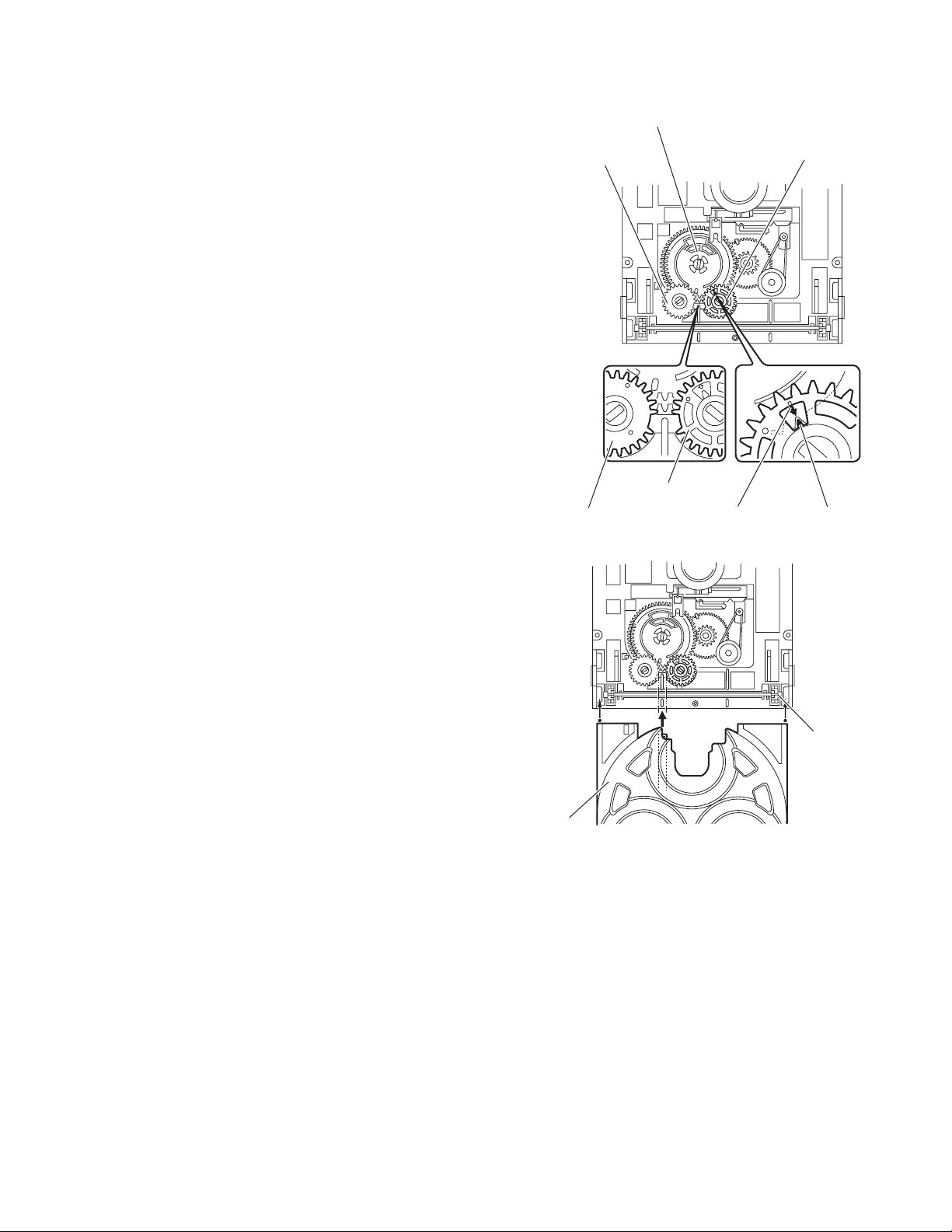
(1) Align the gear cam with the gear tray and then mount the
tray disc. (See Fig.3.)
(2) When assembling the tray disc, take extreme care not en-
gage with gear synchro. (See Fig.4.)
Fig.3
Fig.4
Gear convertor
Gear convertor
Gear tray
Gear tray
Gear tray
Gear cam
Gear cam
timing point
Gear synchro
Tray disc
1-22 (No.MB160)
3.2.3 Removing the sensor board
(See Fig.5)
• Prior to performing the following procedures, remove the tray
disc.
(1) Remove the screw A attaching the sensor board on the
tray disc.
(2) Remove the sensor board releasing the two tabs a.
(3) Disconnect the wire from the connector CW1
on the sensor
board.
Fig.5
3.2.4 Removing the loading motor
(See Figs.6 and 7)
• Prior to performing the following procedures, remove the tray
disc and sensor board.
(1) Remove the screw B attaching the tray roulette and re-
move the tray roulette from the base tray. (See Fig.6.)
(2) Release the tabs b attaching the loading motor on the base
tray in the direction of the arrow and remove the loading
motor. (See Fig.7.)
Reference:
Base tray + Tray roulette = Tray disc
Fig.6
Fig.7
CW1
Sensor board
Tray disc (reverse side)
Ta b a
A
Base tray
Tray roulette
B
Loading moto
r
Tabs b
Base tray (upper side)
(No.MB160)1-23
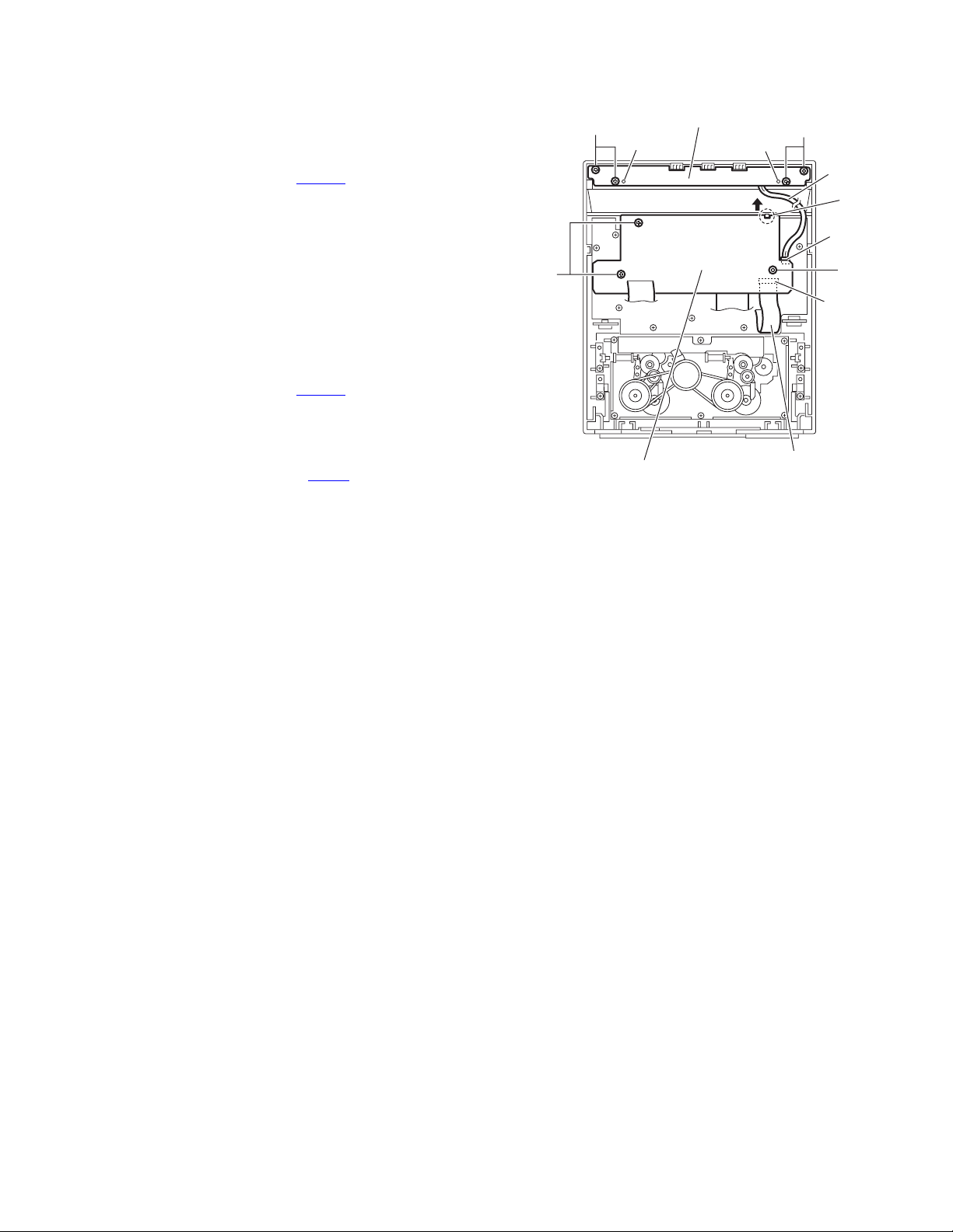
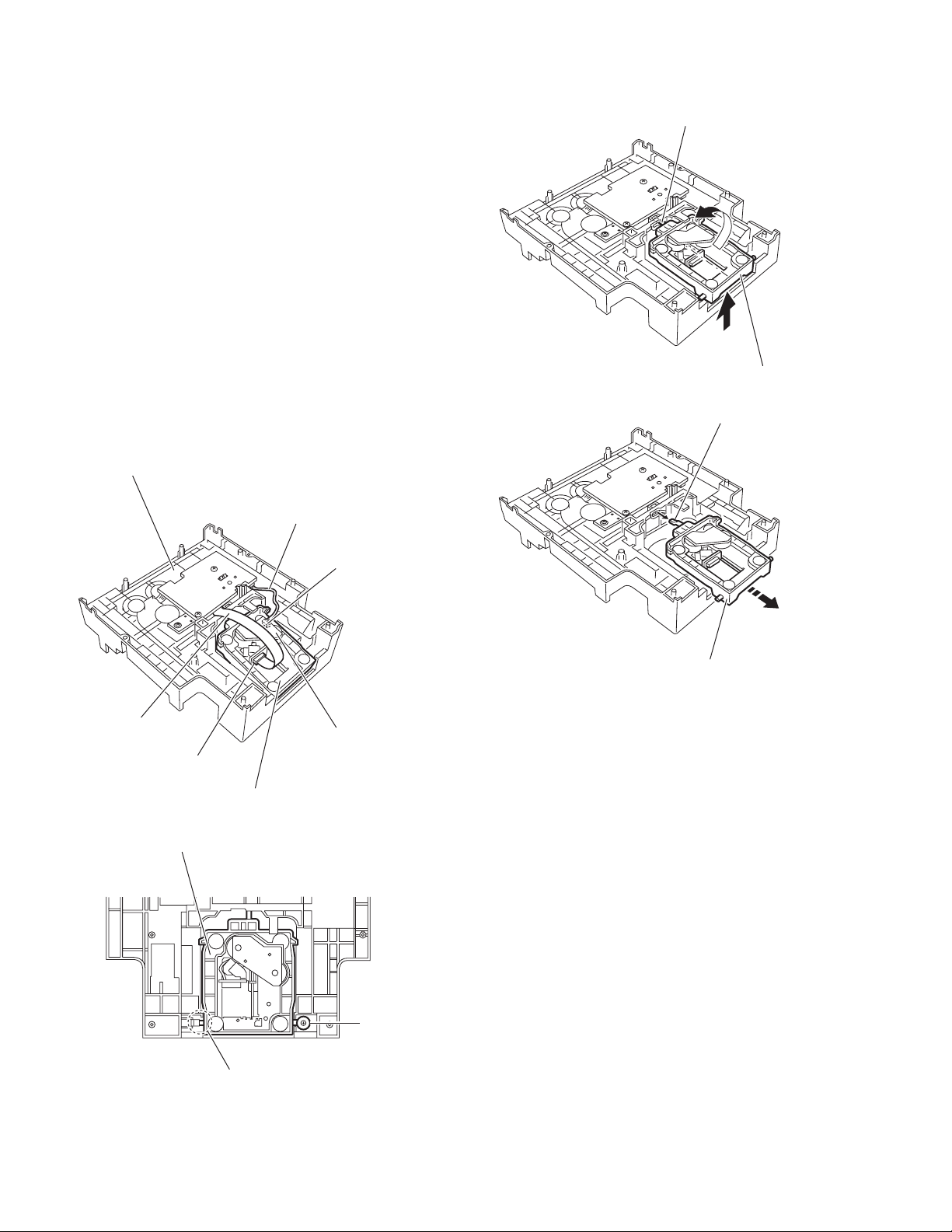
3.2.5 Removing the belt load, CD sub board and switch board
(See Figs.8 and 9)
• Prior to performing the following procedures, remove the tray
disc.
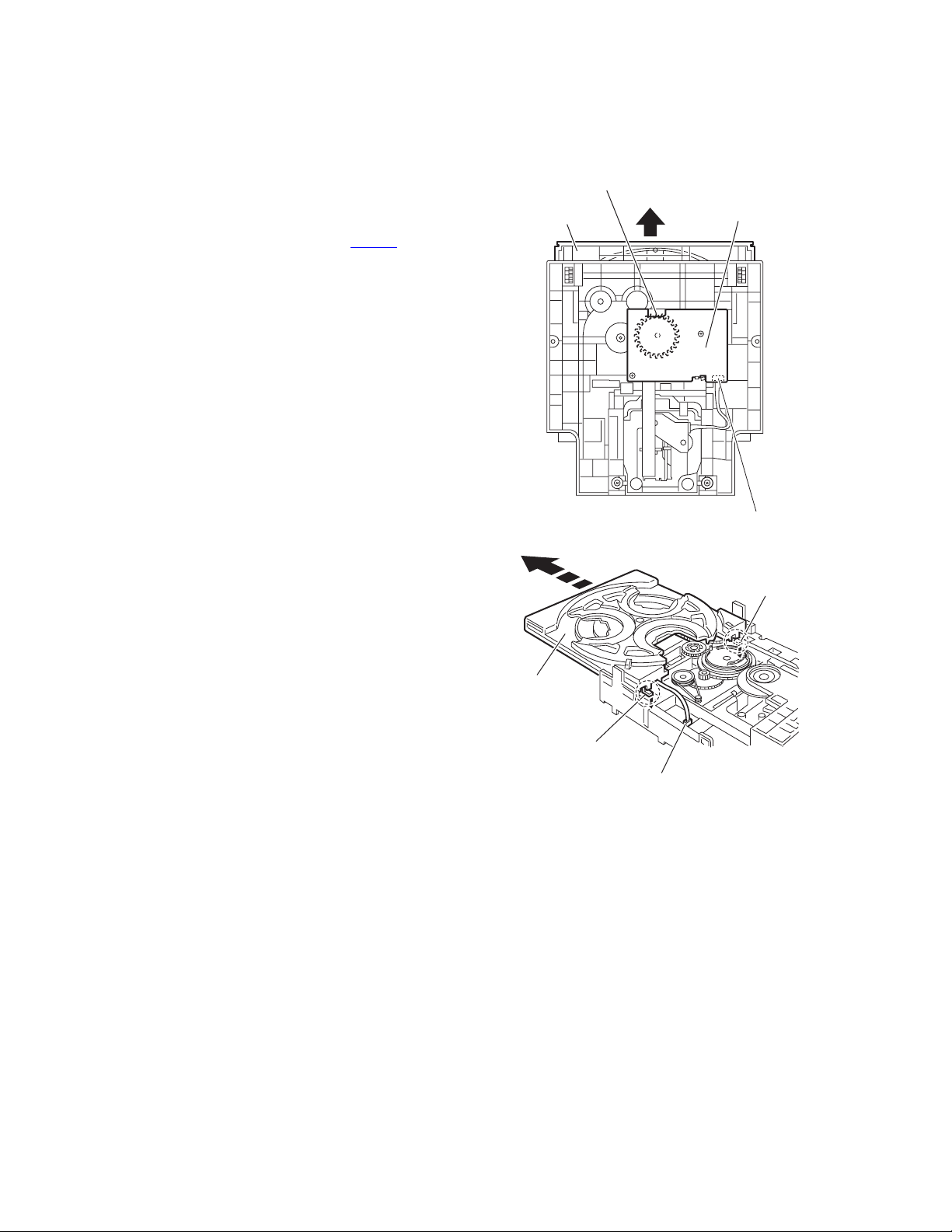
(1) Remove the belt load from the pulley on the top side of the
CD changer mechanism assembly. (See Fig.8.)
Note:
Do not strain the belt load with grease.
(2) Disconnect the card wire from the pickup unit connector on
the bottom side of the CD changer mechanism assembly.
(See Fig.9.)
Attention:
Solder is put up before the card wire is removed from the
pickup unit connector on the CD mechanism assembly.
(When the card wire is removed without putting up sol-
der, the pickup unit might destroy.) (See Fig.9.)
(3) Disconnect the wire from the connector on the CD mecha-
nism board. (See Fig.9.)
(4) Remove the two screws C attaching the CD sub board.
(See Fig.9.)
(5) Release the two tabs c and two tabs d attaching the motor
and then remove the CD sub board. (See Fig.9.)
Reference:
If the tabs c and d are hard to release, it is recommend-
able to unsolder the two soldered parts on the motor ter-
minal of the CD sub board.
(6) Remove the two screws D attaching the switch board and
take out the switch board while releasing the two tabs e at-
taching the switch board outward. (See Fig.9.)
Fig.8
Fig.9
Belt load
CD changer mechanism assembly
CD sub board
CD mechanism
board
Soldered parts
Motor
Switch board
Pickup unit connector
D
Ta bs e
Ta bs d
Ta bs c
C
Card wire
Pickup unit
connector
Soldering
Connecto
r
Wire
C
Card wire
1-24 (No.MB160)
3.2.6 Removing the CD mechanism holder assembly (mechanism included)
(See Figs.9 to 13)
(1) Disconnect the wire from the connector on the CD mecha-
nism board in the CD mechanism holder assembly on the
bottom side of the CD changer mechanism assembly. (See
Fig.10.)
Attention:
Solder is put up before the card wire is removed from the
pickup unit connector on the CD mechanism assembly.
(When the card wire is removed without putting up sol-
der, the pickup unit might destroy.) (See Fig.9.)
(2) Disconnect the card wire from the pickup unit connector.
(See Fig.10.)
(3) Remove the screw E attaching the shaft on the right side of
the CD mechanism holder assembly. (See fig.11.)
(4) Pull outward the stopper fixing the shaft on the left side and
remove the CD mechanism holder assembly from behind
in the direction of the arrow. (See Figs.11 and 12.)
(5) Turn the CD mechanism holder assembly half around the
lift up slide shaft of the CD mechanism holder assembly un-
til the turntable is reversed, and pull out the CD mechanism
holder assembly. (See Figs.12 and 13.)
Fig.10
Fig.11
Fig.12
Fig.13
Connecter
CD mechanism holder assembly
CD changer mechanism assembly
Pickup unit connecter
Card wire
CD mechanism board
Wire
Stopper
CD mechanism holder assembly
E
CD mechanism holder assembly
Lift up slide shaft
CD mechanism holder assembly
Lift up slide shaft
(No.MB160)1-25
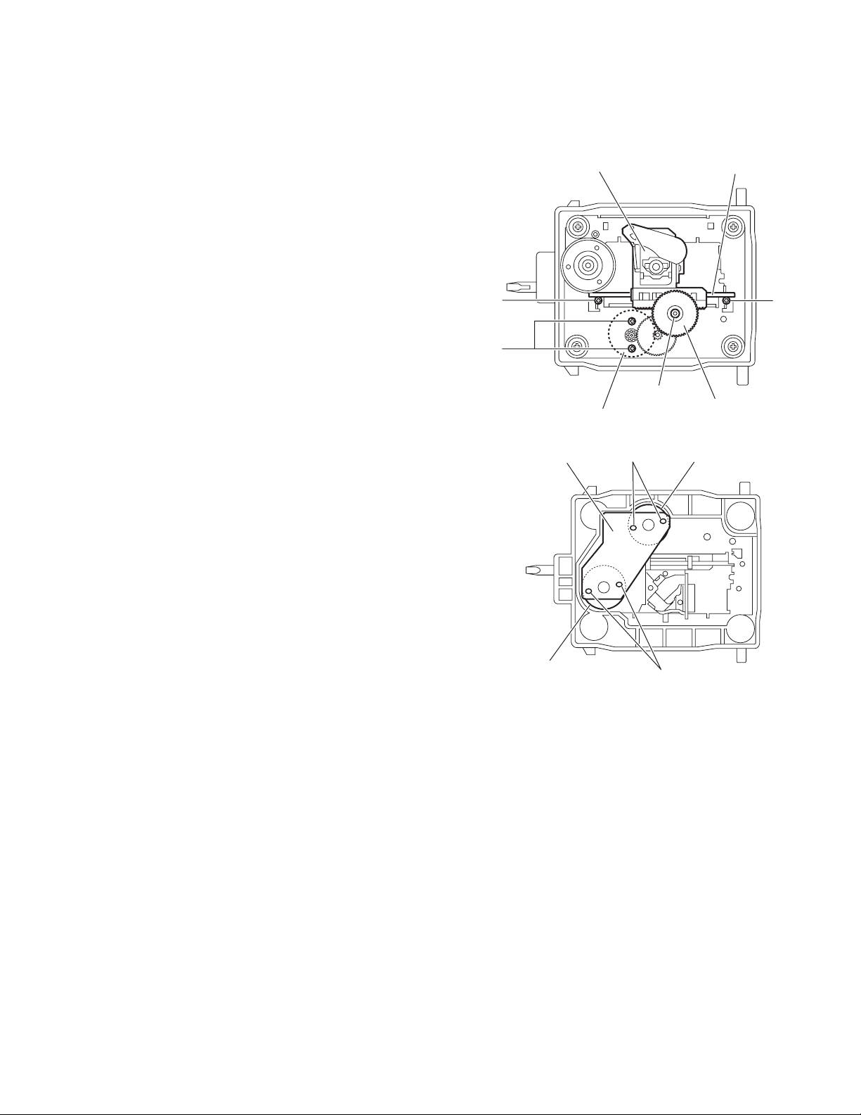
3.3 CD mechanism section
• Prior to performing the following procedures, remove the CD mechanism holder assembly from the CD changer mechanism assem-
bly. (See "3.2.6 Removing the CD mechanism holder assembly".)
3.3.1 Removing the pickup unit
(See Fig.1)
(1) Remove the cut-washer on the feed gear sleeve and pull
out the feed gear.
(2) Remove the two screws A fixing the pickup shaft.
(3) Remove the pickup unit.
3.3.2 Removing the motor board
(See Fig.2.)
(1) Unsolder the motor terminal on the motor board.
(2) Remove the motor board.
3.3.3 Removing the feed motor
(See Fig.1.)
• Prior to performing the following procedures, remove the CD
motor board.
(1) Remove the two screws B and remove the feed motor.
(2) From the bottom side of the CD mechanism holder assem-
bly, take out the feed motor.
3.3.4 Removing the spindle motor
(See Fig.2.)
Reference:
The spindle motor cannot be removed as a single unit.
When removing the spindle motor, change the chassis and
turntable together as a unit.
Fig.1
Fig.2
Pickup unit
Cut-washer
Feed Gear
Pickup shaft
AA
B
Feed motor
Unsolder
Unsolder
Feed motor
Spindle motor
Motor board
1-26 (No.MB160)
3.4 Cassette mechanism section
• Prior to performing the following procedures, remove the cassette deck mechanism assembly. (See "3.1.16 Removing the cassette
deck mechanism assembly".)
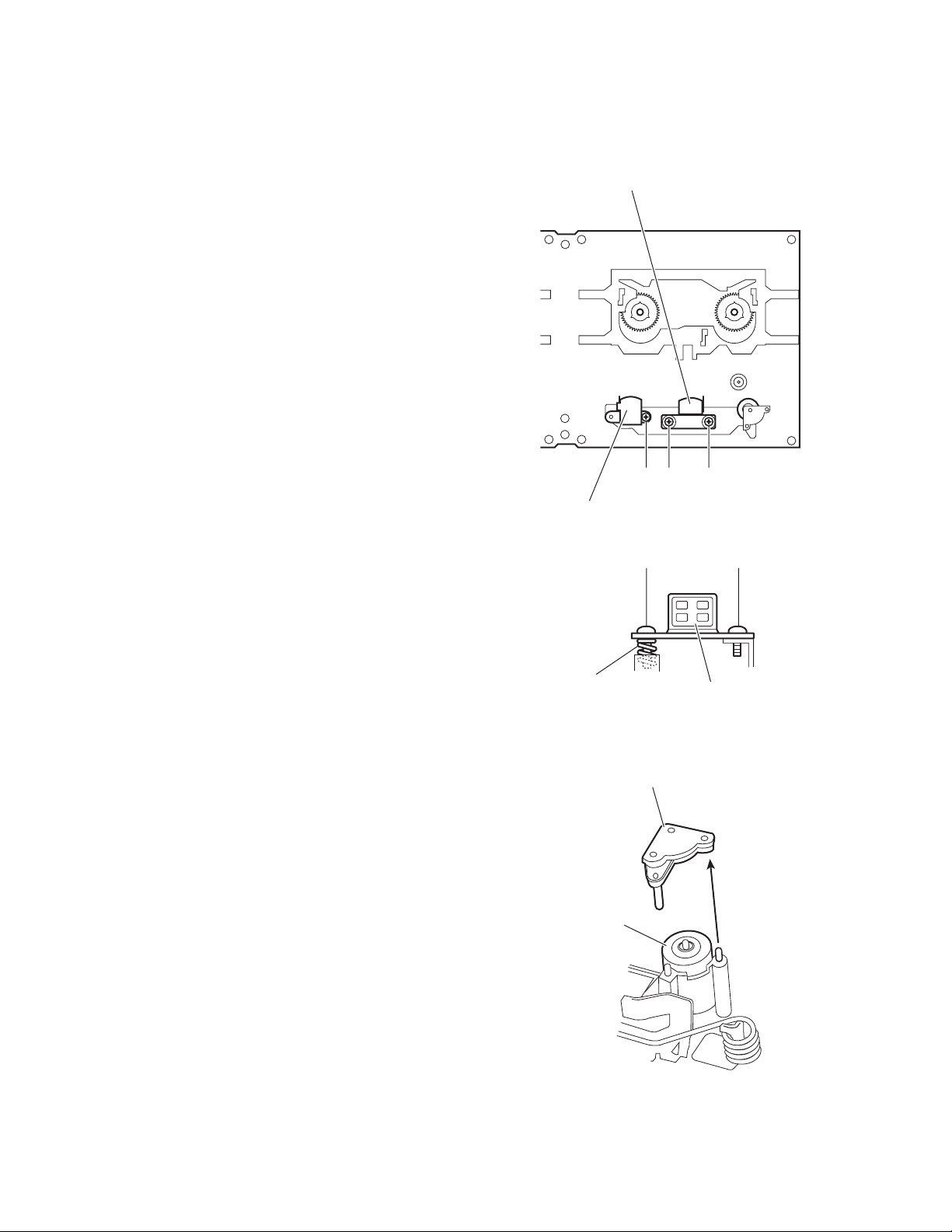
3.4.1 Removing the R/P head
(See Figs.1 and 2)
(1) Remove the screw A attaching the R/P head.
(2) Remove the screw B attaching the R/P head.
Note:
After attaching the R/P head, perform the electrical adjust-
ment. (See "ADJUSTMENT" section.)
3.4.2 Removing the erase head
(See Fig.1)
Remove the screw C attaching the erase head.
Fig.1
Fig.2
3.4.3 Removing the pinch roller
(See Fig.3)
(1) Pull out the pinch roller stopper.
(2) Pull out the pinch roller.
Fig.3
R/P Head
Erase head
ABC
Spring
R/P Head
AB
Pinch roller
Pinch roller stopper
 Loading...