


PC x250b
SERVICE MANUAL
CD PORTABLE COMPONENT SYSTEM
PC-X250
PC-X250
Unit No
SP-PCX250
Contents
Safety precaution ------------------ 2 Block/Wiring Diagram ------------------ 25
Disassembly method -------------- 4 Circuit Diagram -------------------------- 27
Adjustment method ---------------- 6 PCB drawing ----------------------------- 29
TOC read ---------------------------- 10 Assembly ---------------------------------- 32
Major IC Description -------------- 11 Packing ------------------------------------ 42
Unit No
CA-PCX250
Area Suffix
J ---- USA
C ---- Canada
Unit No
SP-PCX250
No. 28001
COPYRIGHT © 2001 VICTOR COMPANY OF JAPAN,LTD (By JCA)
Oct. 2001
PC-X250
CAUTION
Safety Precautions
1. This design of this product contains special hardware and many circuits and components specially for
safety purposes. For continued protection, no changes should be made ti the original design unless
authorised in writing by the manufacturer. Replacement parts must be identical to those used in the
original circuits. Services should be performed by qualified personel only.
2. Alterations of the design or circuitry of the product should not be made. Any design alterations of the
product should not be made. Any design alterations or additions will void the manufacturer's warranty
and will further relieve the manufacturer of responsibility for personal injury or property damage
resulting therefrom.
3. Many eletrical and mechanical parts in the products have special safety-related characteristics.
These characteristics are often not evident from visual inspection nor can the protection afforded by
them necessarily be obtain by using replaement components rated for higher voltage, the Parts
List of Service manual. Electrical components having such features ate identified by the shading on the
schematics and by (
repalcement which does not have the same safety characteristics as the recommended replacement
parts shown in the Parts List of Service manual may create shock, fire, or other hazards.
4. The leads in the products are routed and dressed with ties, clamps, tubing's, barriers and the like to
be separated from live parts, high temperatures parts, moving parts and/or sharp edges for the
prevention of electric shcok and fire hazard. When service is required, the original leat routing and
dress should be observed, and it should be confirmed that they have been returned to normal, after
re-assembling.
! ) on the parts List in the Service Manual. The use of a substitute
5. Leakage current check (Electrical Shock hazard testing)
After re-assembling the product, always perform an isolation check on the exposed metap Parts of the
product (antenna terminals, knobs, metal cabinet, screw heads, headphone jack, control shafts, etc.)
to be sure the product is safe to operate without danger of electrical shock.
Do not use a line isloation transformer during this check.
Plug the AC line cord directly into the AC outlet. Using a "Leakage Current Tester", measure the
leakage current from each ecposed metal parts of the cabinet, particularly and exposed metal
part having a return path to the chassis, to a known good earth ground. Any leakage current must
not exceed 0.5mA AC (r.m.s.)
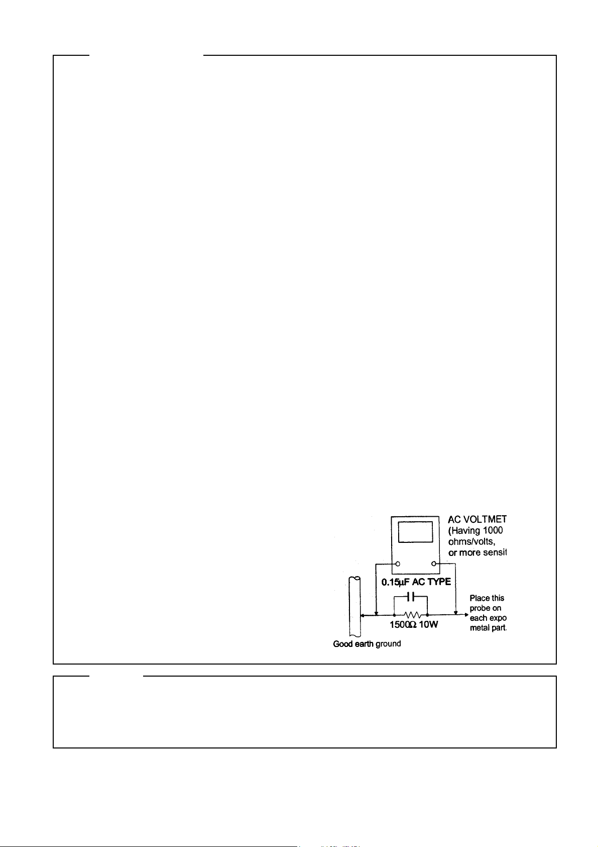
Alternate check method
Plug the AC line cord directly into the AC outlet. Use an AC voltmeter having, 1,000 ohms per
volt or more sensitvity in the following manner. Connect a 1,500 ohm 10W resistor paralleled by a
0.15uF AC-type capacitor between an exposed
metal part and a known good earth ground.
Measure the AC voltage across the resistor with
the AC voltmeter.
Move the resistor connection to each exposed
metal part, particularly and exposed metal part
having a return path to te chassis and
measure the AC voltage across the resistor. Now,
reverse the plug in the AC outlet and repeat
each measurement. Voltage measured Any must
not exceed 0.75 V AC (r.m.s.). This corresponds
to 0.5 mA AC (r.m.s.).
1. This equipment has been designed and manufactured to meet international safety standards.
2. It is the legal responsibility of the repairer to ensure that these safety standards are maintained.
3. repairs must be made in accordance with the relevant safety standards.
4. It is essential that safety critical components are replaced by approved parts.
5. It mains voltage selector is provided, check setting for local voltage.
1 - 2
Warning
Burrs formed during moulding may be left over on some parts of the chassis. Therefore,
pay attention to such burrs in the case of performing repair of this system.
PC-X250
Preventing static electricity
Electrostatic discharge (ESD), which occurs when static electricity stored in the body, fabric, etc. is discharged,
can destroy the laser diode in the traverse unit (optical pcikup). Take care to prevent this when performing repairs.
1.1. Grounding to prevent damage by static electricity
Static electricity in the work area can destroy the optical pickup (laser diode) in devicessuch as DVD players.
Be careful to use proper grounding in the area where repairs are being performed.
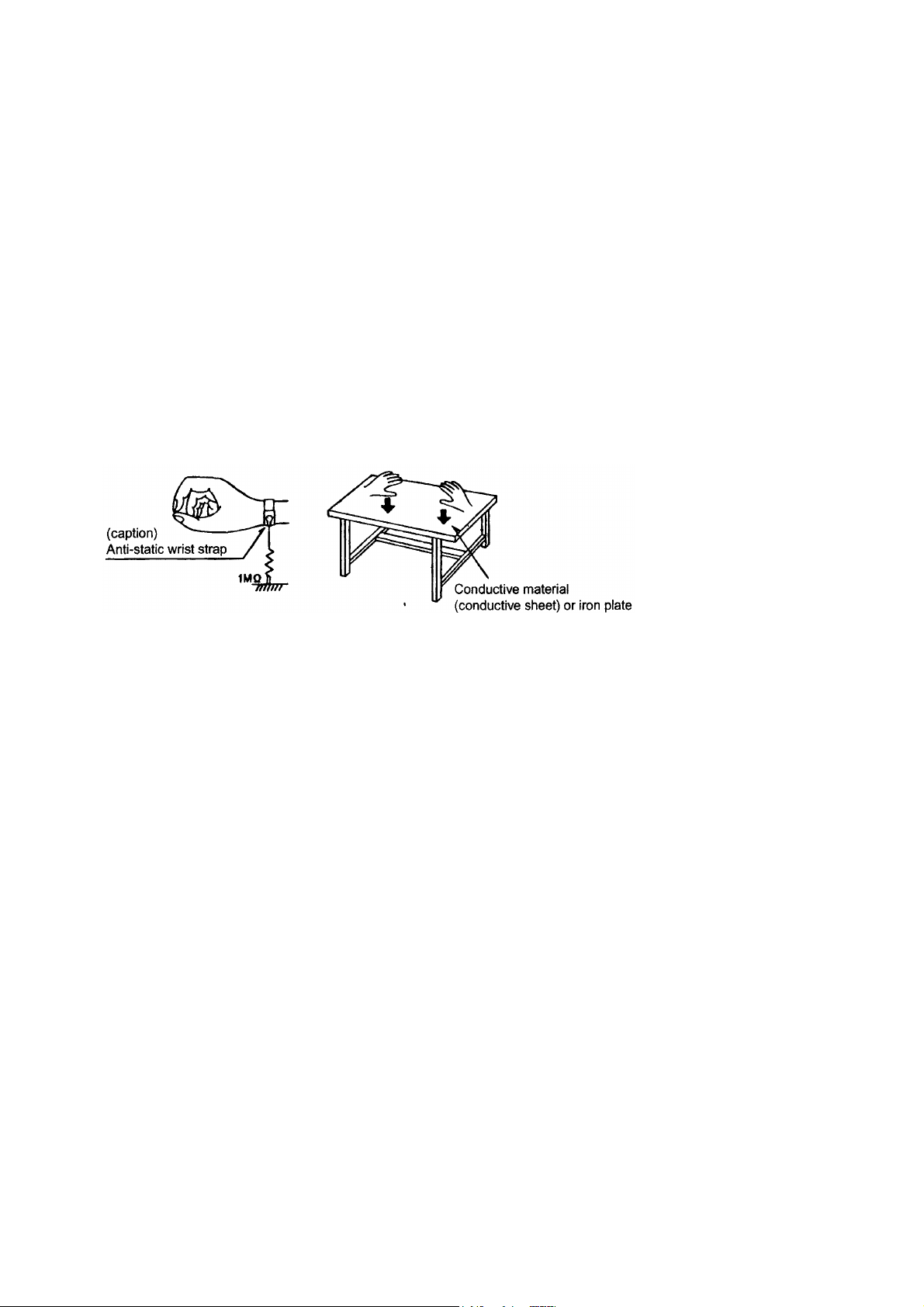
1.1.1. Gound the workbench
1.
Ground the workbench by laying conductive material (such as a conductive sheet) or an iron plate over
it before placing the traverse unit (optical pickup) on it.
1.1.2. Ground yourself
1.
Use an anti-static wrist starp to release and static electricity built up in your body.
1.1.3. Handling the optical pcikup
1.
In order to maintain quality during transport and before installation, both sides of the laser diode on the
replacement optical pickup are storted. After replacement, return the shorted parts to their original condition.
(Refer to the text.)
2.
Do not use a tester to check the condition of the laserdiode in the optical pickup. The tester's internal power
source can easily destory the laser diode.
1.2. Handling the traverse unit (optical pickup)
1.
Do not subject the traverse unit (optical pcikup) to strong shocks, as it is a sensitive, complex unit.
2.
Cut off the shorted part of the flexible cable using nippers, etc. after replacing the optical pickup. For specific
details, refer to the replacement procdeure in the text. Remove the anti-static pin when replacing the traverse
unit. Be careful not to take too long a time when attaching itto the connector.
3.
Handle the flexible cable carefully as it may break when subjected to strong force.
4.
It is not possible to adjust the semi-fixed resistor that adjusts the laser power. Do not return it.
1 - 3
PC-X250
Disassembly method
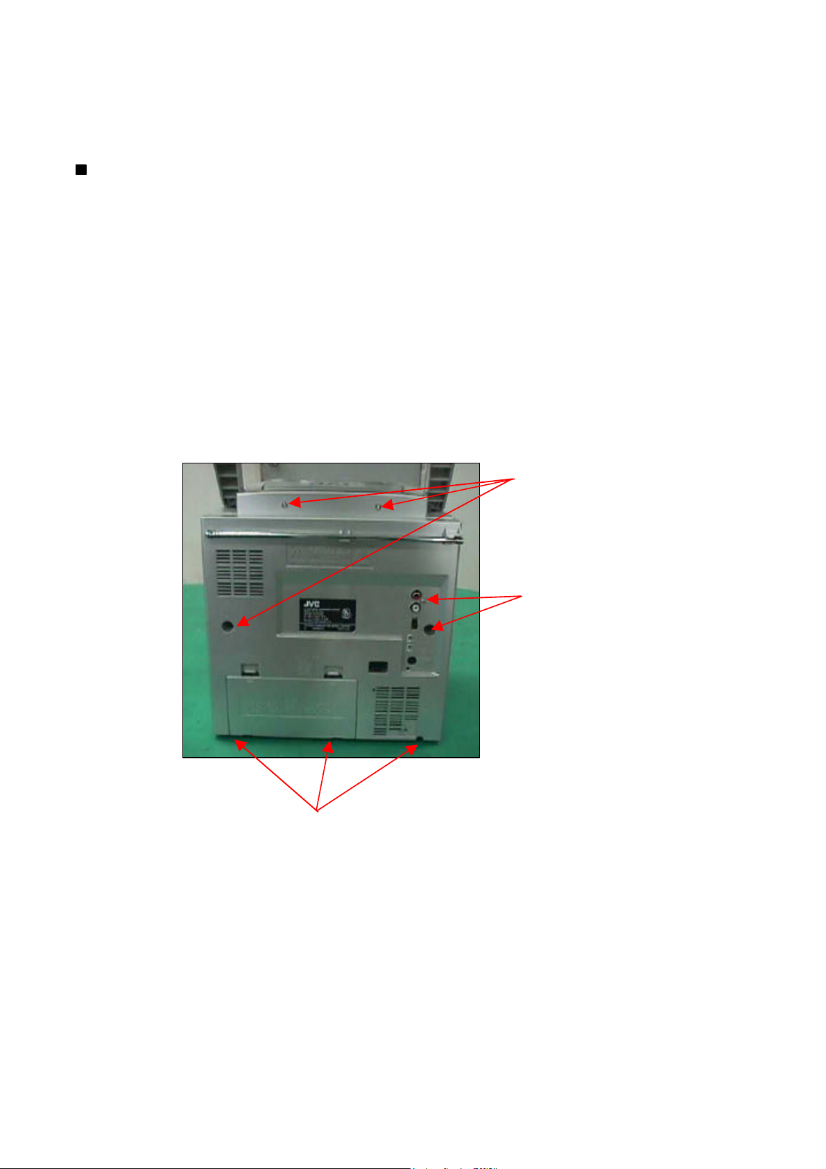
Removing the rear panel
1.
From behind the body, remove the Five screws
A
retaining the rear panel.
2.
Then remove the Two screws
B
retaining the bottom of rear panel.
3.
Take out the rear panel from the body.
Note:
Be careful of the FM antenna white wire, it is connection with the tuner PCB up side.
You can directly take out from the tuner PCB.
When you re-assembly the product, plug the FM antenna white wire into the Tuner PCB's
"FM ANT" position.
Screw A.
Screw A.
Screw B.
1 - 4
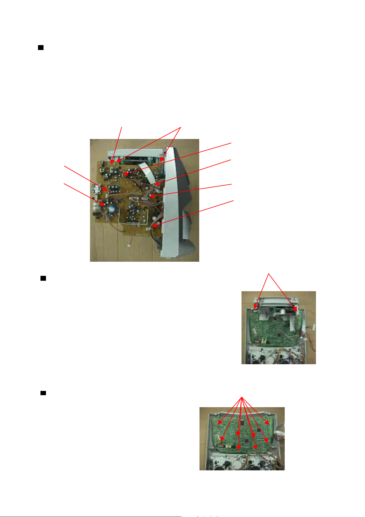
Removing the Audio Board
1.Open & remove the rear panel
2. Remove the Connector CN201, CN202, CN203, CN405, CN502, CN801
& CN301 on the Audio Board.
3. Remove the two Screws C retaining the Audio Board.
CN202 Screw C
CN201
CN502
CN203
CN801 CN405
CN301
PC-X250
Removing the CD Mechanism
1 Open & remove the rear panel
2 Remove the Audio PCB
3 Remove the Two Screws D retaining the CD Tray Backet.
Removing the Tuner PCB Screw E
1 Open & remove the rear panel.
2 Remove the Audio PCB.
3 Remove CD mechanism.
Screw D
4 Remove the Eight Screws E retaining
on the Tuner Board.
1 - 5

PC-X250
Adjustment method
Measurement instruments required for Tuner section
adjustment
Low frequency oscillator Voltage applied to tuner ---------- +B:DC 4.9V
1
This oscillator should have a capacity to output VT:DC 12V
0dBs to 600 at an oscillation frequency of Reference measurement ----- 26.1mV(0.28V)/3
50Hz-20KHz output
Input positions ----- AM : Standard loop antenna
Electronic voltmeter FM : TP1 (hot) and TP2 (GND)
2
Distortion meter
3
Frequency counter Standard measurement position of volume
4
Wow & flutter meter
5
Test tape Bass ----------------------------------------------------- Off
6
TCC-112 : Tape speed and running unevenness (3KHz) Active hoper bass pro ------------------------ Off
TCC-140 : Reference level (1KHz) Up and down adjustment of volume ----- Vol : 23
TCC-182A : Head angle (8KHz) , playback frequency
characteristics (1KHz) and dubbing frequency Precautions for measurement
characteristics (125Hz and 8KHz) 1 Apply 30PF and 33 Kohm to the IF sweeper output
Because of frequency - mixed tape with 63 , 1 , 10 and side and 0.082UF and 100 Kohm in series to the
14KHz (250nWb/m -24dB) , use this tape together sweeper input side .
with a filter . 2 The IF sweeper output level should be made as
Black tape low as possible within the adjustable range .
7
TYPE I : AC - 225 3 Since the IF sweeper is a fixed device , there is no
TYPE II : AC - 514 need to adjust this sweeper .
8 Torque gauge : For play and back tension 4 Since a ceramic oscillator is used , there is no need
FWD(TW2111A) , REV(TW2121a) and FF/REW(TW2231A) to perform any MIX adjustment .
5 Since a fixed coil is used , there is no need to
Measurement conditions adjust the FM tracking .
6 The input and output earth systems are separated .
Power supply voltage ---------------- AC 120V (60Hz) In case of simultaneously measuring the voltage in
Reference output -------------- Speaker : 0.866V/3 both of the input and output systems with an
Headphone : 0.245V/32 electronic voltmeter for two channels , therefore , the
Reference frequency and ----- 1KHz , AUX : 450~500mV earth should be connected particularly carefully .
input level 7 In the case of BTL connection amp. , the minus
Input for confirming recording and ------- AUX : -28dBs terminal of speaker is not for earthing . Therefore , be
playback characteristics sure not to connect any other earth terminal to this
Measurement output terminal ---------- Speaker J3002 terminal . This system is of an BTL system .
* Load resistance --------------------------- 3 8 For connecting a dummy resistor when measuring
the output , use the wire with a greater code size .
Radio Input signal 9 Whenever any mixed tape is used , use the band
pass filter (DV-12V)
AM frequency -------------------------------- 400Hz
AM modulation ---------------------------------- 30%
FM frequency --------------------------------- 1 KHz
FM frequency deviation ------------------------ 22.5KHz
1 - 6
TAPE DECK ADJUSTMENTS
1 HEAD AZIMUTH ADJUSTMET
( 1 ) Load the test tape TCC-182A 8KHz for azimuth
adjustment.
( 2 ) Press the PLAY button.
( 3 ) Use a cross-tip screwdriver to turn the screw for azimuth
adjustment so that the left and right output are maximized
( 4 ) Press the STOP button
( 5 ) After completion of the adjustment. Use thread lock(TB-1401B)
to secure the azimuth-adjustment screw.
2 AC BIAS FREQUENCY ADJUSTMENTS
( 1 ) Connect frequency counter to CN202(BS);
( 2 ) R/P swith in recording state;
( 3 ) Adjusting T801 use a plastic screwdriver, AC bias frepuency ;61kHz +/- 1kHz..
PC-X250
3 TAPE SPEED ADJUSTMENT
( 1 ) Insert the test tape(MTT-111N,3,000 HZ)
( 2 ) Press the PLAY button.
( 3 ) Use a flat-tip screwdriver to turn the VR 501.
Adjust VR501 so that the frequency counter
become 3,000Hz
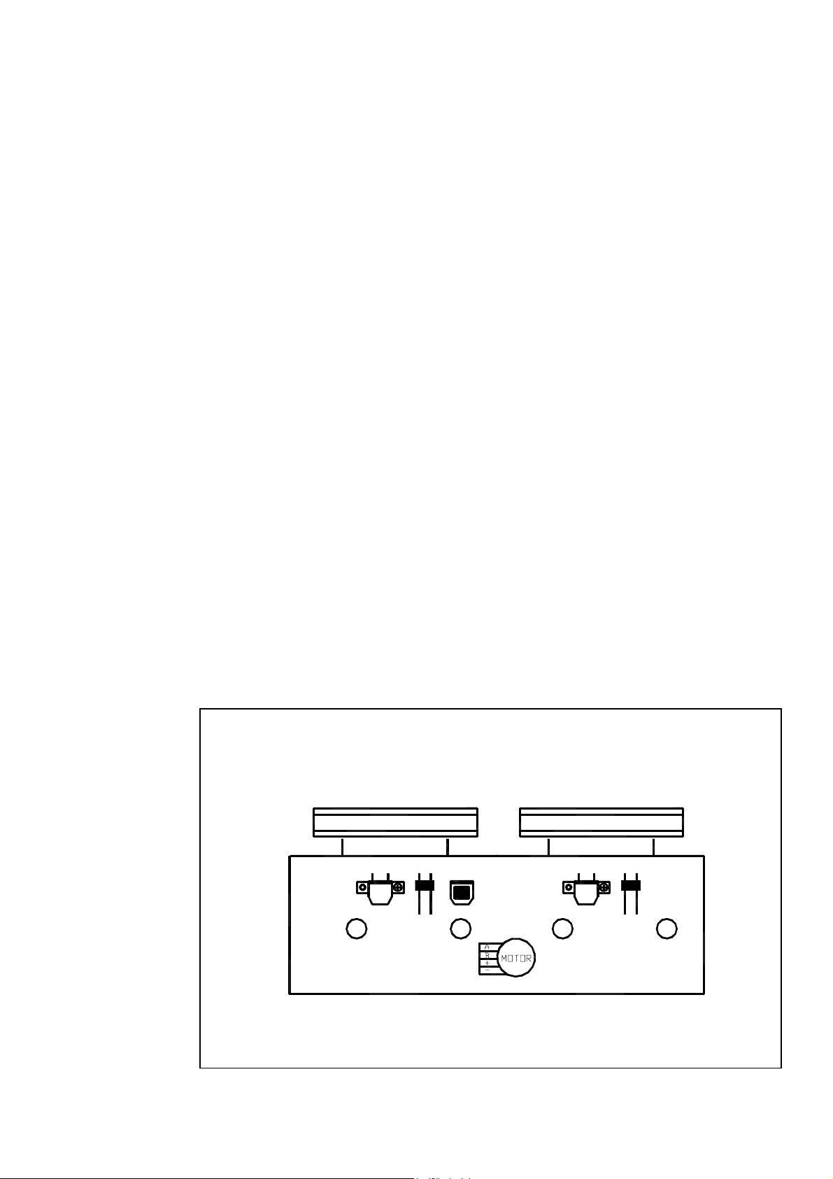
TAPE HEAD AND SPEED ADJUSTMENT DIAGRAM
CASS DECK
E HEAD
A
L. SW
P/R HEAD
P HEAD
A DECK B DECK
A
L. SW
1 - 7

PC-X250
Tape recorder section
Items Measrrnment methed
Confirmation Test tape 1 Playback the test tape TCC-182A (8KHz) Maximum Adjust the head
of head angle :TA-182A(8KHz) 2 With the recording & playback mechanism, output azimuth screw
Confirmation Test tape Adjust VR501 so that the frequrncy counter Tape speed VR501
of tape speed :TCC-112(3000Hz) reading becomes 3,010Hz +/-15Hz when of deck
Measurement Standard Adjusting]
conditions Values positions
Measurement output adjust the head azimuth screw so that the only when the
terminal left and right output levers become head has been
:Speaker terminal maximum, After adjustment, lock the head changed
Sperker R azimuth at least by half turn.
(Load resistance:3 )
:Headphone terminal
playing back the test tape TCC-112 (3000Hz) with :3,010Hz
Measurement output playback and recording mechanism after +/-15Hz
terninal ending forward winding if the taoe.
:Headphone terminal
Reference Values for Confirmation Items
ITEMS Measrrnment methed
Wow & flutter Test tape When the test tape TCC-112 (3000Hz) has been 0.25% or
Measurement Standard Adjusting]
conditions Values positions
:TCC-112(3000Hz) played back with the recording and playback less
mecganism at the beginning of forward (WRMS)
Measurement outut winding, the frequency counter reading of
terminal wow & flutter should be 0.25% or less
:Headphone terminal (WRMS).
1 - 8
 Loading...