


U |
|
|
|
E |
|
|
DV VIDEO CASSETTE RECORDER
BR-DV3000U |
INSTRUCTION MANUAL |
|
OPERATE
EJECT
|
|
|
|
|
MENIU |
|
Mini |
A.DUB |
REC |
PLAY |
PAUSE |
|
|
|
DVCAM NTSC PAL REC INH. |
|
|
PROFESSIONAL |
|
CH-1/3 |
|
|
|
|
|
|
|
SET |
|
MIC |
REMOTE SEL. |
INPUT SEL. |
REW |
STOP |
FF |
|
SERIAL |
LINE |
CH-2/4 |
|
|
|
9PIN WIRELESS |
DV Y/C |
BR-DV3000 |
|
|
DV VIDEO CASSETTE RECORDER |
|||
DV VIDEOKASSETTENREKORDER |
|||
ENREGISTREUR A CASSETTE DIGITAL VIDEO |
|||
DV VIDEOREGISTRATORE |
|
||
UNIDAD GRABADORA DE VÍDEO DV |
|||
BR-DV3000E |
INSTRUCTION MANUAL |
||
BEDIENUNGSANLEITUNG |
|||
|
|
||
|
|
MODE D’EMPLOI |
|
|
|
||
|
|
ISTRUZIONI PER L’USO |
|
|
|
||
|
MANUAL DE INSTRUCCIONES |
||
OPERATE
|
Mini |
A.DUB |
PROFESSIONAL |
|
|
MIC |
REMOTE SEL. |
INPUT SEL. |
|
SERIAL |
LINE |
|
9PIN WIRELESS |
DV Y/C |
|
|
EJECT |
|
|
MENIU |
REC |
PLAY |
PAUSE |
DVCAM NTSC PAL REC INH. |
|
|
CH-1/3 |
|
SET |
REW |
STOP |
FF |
CH-2/4 |
|
|
BR-DV3000 |
|
|
This instruction book is made from 100% recycled paper.
Thank you for purchasing this JVC product. Before operating this unit, please read the instructions carefully to ensure the best possible performance.
For Customer Use: |
|
|
|
Enter below the Serial No. which is |
|
|
located on the rear of cabinet. Retain |
|
|
this information for future reference. |
|
|
Model No. |
BR-DV3000U |
|
Serial No. |
|
Thank you for purchasing this JVC product. Before operating this unit, please read the instructions carefully to unsure the best possible performance.
This instruction book is made from 100% recycled paper.
LLT0024-001A
LLT0025-001A
U |
|
|
|
E |
|
|
1.Read all of these instructions.
2.Save these instructions for later use.
3.All warnings on the product and in the operating instructions should be adhered to.
4.Unplug this appliance system from the wall outlet before cleaning. Do not use liquid cleaners or aerosol cleaners. Use a damp cloth for cleaning.
5.Do not use attachments not recommended by the appliance manufacturer as they may cause hazards.
6.Do not use this appliance near water – for example, near a bathtub, washbowl, kitchen sink, or laundry tub, in a wet basement, or near a swimming pool, etc.
7.Do not place this appliance on an unstable cart, stand, or table. The appliance
may fall, causing serious injury to a child or adult, and serious damage to the 


appliance. Use only with a cart or stand recommended by the manufacturer, or sold with the appliance. Wall or shelf mounting should follow the manufacturer’s instructions, and should use a mounting kit approved by the manufacturer. An appliance and cart combination should be moved with care. Quick stops, excessive force, and uneven surfaces may cause the appliance and cart combination to overturn.
8.Slots and openings in the cabinet and the back or bottom are provided for
ventilation, and to insure reliable operation of the appliance and to protect it from overheating, these openings must not be blocked or covered.The openings should never be blocked by placing the appliance on a bed, sofa, rug, or other similar surface. This appliance should never be placed near or over a radiator or heat register.This appliance should not be placed in a built-in installation such as a bookcase unless proper ventilation is provided.
9.This appliance should be operated only from the type of power source indicated on the marking label. If you are not sure of the type of power supplied to your home, consult your dealer or local power company. For appliance designed to operate from battery power, refer to the operating instructions.
10.This appliance system is equipped with a 3-wire grounding type plug (a plug having a third (grounding) pin). This plug will only fit into a grounding-type power outlet. This is a safety feature. If you are unable to insert the plug into the outlet, contact your electrician to replace your obsolete outlet. Do not defeat the safety purpose of the grounding plug.
11.For added protection for this product during a lightning storm, or when it is left unattended and unused for long periods of time, unplug it from the wall outlet and disconnect the antenna or cable system. This will prevent damage to the product due to lightning and power-line surges.
12.Do not allow anything to rest on the power cord. Do not locate this appliance where the cord will be abused by persons walking on it.
13.Follow all warnings and instructions marked on the appliance.
14.Do not overload wall outlets and extension cords as this can result in fire or electric shock.
15.Never push objects of any kind into this appliance through cabinet slots as they may touch dangerous voltage points or short out parts that could result in a fire or electric shock. Never spill liquid of any kind on the appliance.
16.Do not attempt to service this appliance yourself as opening or removing covers may expose you to dangerous voltage or other hazards. Refer all servicing to qualified service personnel.
17.Unplug this appliance from the wall outlet and refer servicing to qualified service personnel under the following conditions:
a.When the power cord or plug is damaged or frayed.
b.If liquid has been spilled into the appliance.
c.If the appliance has been exposed to rain or water.
d.If the appliance does not operate normally by following the operating instructions. Adjust only those controls that are covered by the operating instructions as improper adjustment of other controls may result in damage and will often require extensive work by a qualified technician to restore the appliance to normal operation.
e.If the appliance has been dropped or the cabinet has been damaged.
f.When the appliance exhibits a distinct change in performance – this indicates a need for service.
18.When replacement parts are required, be sure the service technician has used replacement parts specified by the manufacturer that have the same characteristics as the original part. Unauthorized substitutions may result in fire, electric shock, or other hazards.
19.Upon completion of any service or repairs to this appliance, ask the service technician to perform routine safety checks to determine that the appliance is in safe operating condition.
Supplement |
|
|
This equipment is in conformity with the provisions and protection requirements of the |
||
corresponding European Directives. This equipment is designed for professional video |
||
appliances and can be used in the following environments: |
|
|
5Residential (including both of the location type class 1 and 2 found in IEC 1000-2-5) |
||
5Commercial and light industrial (including, for example, theatres) |
|
|
5Urban outdoors (based on the definition of location type class 6 in IEC 1000-2-5) |
||
This apparatus is designed for rack mounting or is used close to other apparatus. |
||
In order to keep the best performance and furthermore for electromagnetic compatibility |
||
we recommend to use cables not exceeding the following lengths: |
|
|
Port |
Cable |
Length |
AUDIO |
SHIELDED CABLE |
10 meters |
LINE |
COAXIAL CABLE |
10 meters |
Y/C |
COAXIAL CABLE |
10 meters |
DV |
SHIELDED TWIST PAIR CABLE |
4 meters |
REMOTE |
TWIST PAIR CABLE |
5 meters |
The inrush current of this apparatus is 1.7 amperes. |
|
|
Caution: |
|
|
5Where there are strong electromagnetic waves or magnetism, for example near a radio or TV transmitter, transformer, motor, etc., the picture and sound may be disturbed. In
such a case, please keep the apparatus away from the sources of the disturbance.
2
E-2

SAFETY PRECAUTIONS
U |
|
|
|
E |
|
|
SAFETY PRECAUTIONS
CAUTION
RISK OF ELECTRIC SHOCK
DO NOT OPEN
CAUTION: TO REDUCE THE RISK OF ELECTRIC SHOCK, DO NOT REMOVE COVER (OR BACK). NO USER-SERVICEABLE PARTS INSIDE. REFER SERVICING TO QUALIFIED SERVICE PERSONNEL
The lightning flash with arrowhead symbol, within an equilateral triangle, is intended to alert the user to the presence of uninsulated “dangerous voltage” within the product’s enclosure that may be of sufficient magnitude to constitute a risk of electric shock to persons.
The exclamation point within an equilateral triangle is intended to alert the user to the presence of important operating and maintenance (servicing) instructions in the literature accompanying the appliance.
WARNING: TO REDUCE THE RISK OF FIRE OR ELECTRIC SHOCK, DO NOT EXPOSE THIS APPLIANCE TO RAIN OR MOISTURE.
This unit should be used with 120 V AC only.
CAUTION: To prevent electric shocks and fire hazards, DO NOT use any other power source.
NOTE: The rating plate (serial number plate) is on the rear of the unit.
INFORMATION
This equipment has been tested and found to comply with the limits for a Class B digital device, pursuant to Part 15 of the FCC Rules. These limits are designed to provide reasonable protection against harmful interference in a residential installation. This equipment generates, uses, and can radiate radio frequency energy and, if not installed and used in accordance with the instructions, may cause harmful interference to radio communications. However, there is no guarantee that interference will not occur in a particular installation. If this equipment does cause harmful interference to radio or television reception, which can be determined by turning the equipment off and on, the user is encouraged to try to correct the interference by one or more of the following measures:
●Reorient or relocate the receiving antenna.
●Increase the separation between the equipment and receiver.
●Connect the equipment into an outlet on a circuit different from that to which the receiver is connected.
●Consult the dealer or an experienced radio/TV technician for help.
CAUTION
CHANGES OR MODIFICATIONS NOT APPROVED BY JVC COULD VOID USER’S AUTHORITY TO OPERATE THE EQUIPMENT.
THIS DEVICE COMPLIES WITH PART 15 OF THE FCC RULES. OPERATION IS SUBJECT TO THE FOLLOWING TWO CONDITIONS: (1) THIS DEVICE MAY NOT CAUSE HARMFUL INTERFERENCE, AND (2) THIS DEVICE MUST ACCEPT ANY INTERFERENCE RECEIVED, INCLUDING INTERFERENCE THAT MAY CAUSE UNDESIRED OPERATION.
ATTENTION
RISQUE D’ELECTROCUTION
NE PAS OUVRIR
ATTENTION: POUR EVITER TOUT RISQUE D’ELECTROCUTION NE PAS OUVRIR LE BOITER. AUCUNE PIECE INTERIEURE N’EST A REGLER PAR L’UTILISATEUR. SE REFERER A UN AGENT QUALIFIE EN CAS DE PROBLEME.
Le symbole de l’éclair à l’intérieur d’un triangle équilatéral est destiné à alerter l’utilisateur sur la présence d’une “tension dangereuse” non isolée dans le boîtier du produit. Cette tension est suffisante pour provoquer l’électrocution de personnes.
Le point d’exclamation à l’intérieur d’un triangle équilatéral est destiné à alerter l’utilisateur sur la présence d’opérations d’entretien importantes au sujet desquelles des renseignements se trouvent dans le manuel d’instructions.
*Ces symboles ne sont utilisés qu’aux Etats-Unis.
AVERTISSEMENT: POUR EVITER LES RISQUES D’INCENDIE OU D’ELECTROCUTION, NE PAS EXPOSER L’APPAREIL A L’HUMIDITE OU A
LA PLUIE.
Ce magnétoscope ne doit être utilisé que sur du courant alternatif en 120 V.
ATTENTION: Afin d’éviter tout resque d’incendie ou d’électrocution, ne pas utiliser d’autres sources d’alimentation électrique.
REMARQUE: La plaque d’identification (numéro de série) se trouve sur le panneau arrière de l’appareil.
WARNING:
The battery used in the BR-DV3000U must be replaced by a JVC authorized service dealer only.
This digital apparatus does not exceed the Class B limits for radio noise emissions from digital apparatus as set out in the interference-causing equipment standard entitled “Digital Apparatus”, ICES-003 of the Department of Communications.
Cet appareil numérique respecte les limites de bruits radioélectriques applicables aux appareils numériques de Classe B prescrites dans la norme sur le matériel brouilleur: “Appareils Numériques”, NMB-003 édictée par le ministre des Communications.
Warning Notice
FOR YOUR SAFETY (Australia)
1.Insert this plug only into effectively earthed three-pin power outlet.
2.If any doubt exists regarding the earthing, consult a qualified electrician.
3.Extension cord, if used, must be three-core correctly wired.
IMPORTANT (In the United Kingdom) |
||||
Mains Supply (AC 230 V `) |
||||
WARNING – THIS APPARATUS |
||||
MUST BE EARTHED |
||||
The wires in this mains lead are coloured in |
||||
accordance with the following code; |
||||
GREEN-and-YELLOW |
: |
EARTH |
||
BLUE |
: |
NEUTRAL |
||
BROWN |
: |
LIVE |
||
As the colours of the wires in the mains lead of |
||||
this apparatus may not correspond with the |
||||
coloured markings identifying the terminals in |
||||
your plug, proceed as follows. |
|
|||
The wire which is coloured GREEN-AND- |
||||
YELLOW must be connected to the terminal in |
||||
the plug which is marked with the letter E or by |
||||
the safety earth symbol |
|
|
or coloured GREEN |
|
|
|
|||
or GREEN-AND-YELLOW. The wire which is |
||||
coloured BLUE must be connected to the terminal |
||||
which is marked with the letter N or which is |
||||
coloured BLACK. The wire which is coloured |
||||
BROWN must be connected to the terminal |
||||
which is marked with the letter L or coloured |
||||
RED. |
|
|
||
POWER SYSTEM Connection to the mains supply This unit operates on voltage of 220 V to 240 V AC, 50 Hz/60 Hz.
WARNING:
TO REDUCE THE RISK OF FIRE OR ELECTRIC SHOCK, DO NOT EXPOSE THIS APPLIANCE TO RAIN OR MOISTURE.
CAUTION
To prevent electric shock, do not open the cabinet. No user serviceable parts inside. Refer servicing to qualified service personnel.
Note:
The rating plate and the safety caution are on the rear of the unit.
The OPERATE button does not completely shut off mains power from the unit, but switches operating current on and off.
WARNING
It should be noted that it may be unlawful to rerecord pre-recorded tapes, records, or discs without the consent of the owner of copyright in the sound or video recording, broadcast, or cable programme and in any literary, dramatic, musical or artistic work embodied therein.
Caution for AC Mains Lead |
|
FOR YOUR SAFETY PLEASE READ THE FOLLOWING TEXT CAREFULLY. |
|
This product is equipped with 2 types of AC cable. One is for continental Europe, etc. and the other one |
|
is only for U.K. |
|
Appropriate mains cable must be used in each local area, since the other type of mains cable is not |
|
suitable. |
|
FOR CONTINENTAL EUROPE, ETC. |
FOR U.K. ONLY |
Not to be used in the U.K. |
If the plug supplied is not suitable for your |
|
socket outlet, it should be cut off and |
|
appropriate one fitted. |
3
E-3

Thank you for purchasing our DV Video Cassette Recorder BR-DV3000.
As this is a DV-format video cassette recorder, |
||
video cassettes with the |
or |
logos can |
be used with it. |
|
|
DVCAM cassettes can be recorded in DV for- |
||
mat. |
|
|
ThisVTR features dual support for NTSC and PAL. |
||
Certain functions however, are supported by only |
||
one signal system.They are indicated with (NTSC |
||
only) or (PAL only). |
|
|
●In order to prevent crumpling due to tape slack, please do not perform important recording within the first and last 2 – 3 minutes run of the tape.
●Recorded video (music) is meant for personal entertainment only and must not be used for other purposes without the prior consent of the copyright owner.
●Our company shall not guarantee the content of any recording effort should this VTR fail to record normally due to defects, either of the main unit itself or the video cassette tape.
4
MAIN FEATURES
●DV format
High picture and sound quality by digital technology.
●Compatible mechanisms for standard/mini DV cassettes
It records on and plays back DV cassettes of the standard and mini size. (SP mode only)
DVCAM cassettes can be recorded in DV format.
A tape recorded with the DVCAM format can be used only for playback for this VTR.
●Equipped with composite and Y/C input & output terminal devices.
● |
Equipped with DV IN/OUT terminals. (IEEE1394) |
|
It can exchange digital signals with IEEE1394- |
|
compatible devices. |
● |
Dual support for NTSC/PAL |
|
It automatically determines the signal system |
|
when playing back or receiving DV signal input. |
|
It supports composite or Y/C signal input with |
|
the use of a switch. |
● |
Wireless/wired remote control |
|
It can be controlled with the provided wireless |
|
remote controller or the optional wired remote |
|
controller RM-G30. |
● |
Support for RS-422A interface |
|
It can be used as a player for an editing system |
|
that uses the RS-422A-compatible editing re- |
|
mote controller RM-G820. |
● |
Recording/playback of time codes |
● |
Audio-dubbing (after-recording) function |
|
Audio dubbing at a sampling frequency of 32kHz |
|
is allowed on CH3 and CH4 (except during DV |
|
input). |
● |
Backup recording function |
|
By linking with other DV devices, long-duration |
|
continuous recording is possible. |
● |
Indexed search and blank search function |
|
It can search for indexed signal recorded posi- |
|
tions or unrecorded parts. |
● |
Repeat play function |
|
There are 3 types of repeat function. (Index/ |
|
Video End/ Tape End) |
● |
Can be placed in an upright position |
|
With the use of the provided stand, it can be |
|
positioned upright. |
TABLE OF CONTENTS |
|
INTRODUCTION |
|
Precautions .................................................... |
6 |
Daily maintenance and regular inspection ..... |
7 |
Precautions on the use of cleaning tape ........ |
8 |
Cassette tape ................................................. |
8 |
Condensation ................................................. |
9 |
NAMES AND FUNCTIONS OF VARIOUS PARTS |
|
Front panel ................................................... |
10 |
Rear panel .................................................... |
14 |
Wireless remote controller ........................... |
16 |
ON-SCREEN DISPLAY |
|
Regarding on-screen display ........................ |
18 |
Status display ............................................... |
19 |
Event display ................................................ |
21 |
Alarm display ................................................ |
22 |
PREPARATION |
|
Provided wireless remote controller ............. |
24 |
Power ........................................................... |
26 |
Selecting the NTSC/PAL signal system ....... |
28 |
OPERATION LOCK mode ............................ |
29 |
Loading/ejecting cassettes ........................... |
30 |
Setting/displaying date and time .................. |
31 |
EDIT |
|
Using the unit in an editing system .............. |
50 |
MENU SCREEN |
|
Structure of the menu ................................... |
53 |
Setting the menu .......................................... |
54 |
Contents of the menus ................................. |
56 |
OTHERS |
|
Placing the unit in an upright position .......... |
65 |
Warning display ............................................ |
66 |
Troubleshooting ............................................ |
68 |
Checking the hour meter .............................. |
69 |
Specification ................................................. |
70 |
RECORDING |
|
Connection and setting ................................ |
33 |
Setting time codes ........................................ |
36 |
Recording method ........................................ |
38 |
Audio dubbing .............................................. |
39 |
Backup recording function ............................ |
40 |
Recording using the serial remote terminal ... |
41 |
PLAYBACK |
|
Connection/setting ....................................... |
42 |
Basic playback method ................................ |
44 |
Special playback function ............................. |
45 |
Locate function ............................................. |
47 |
Repeat playback ........................................... |
48 |
Selecting playback audio output ................... |
49 |
5
INTRODUCTION |
|
Precautions |
|
Place of storage and use |
|
Please avoid storing or using this VTR in the fol- |
|
lowing places: |
|
● |
Extremely hot or cold places beyond the al- |
|
lowable temperature for operation (5˚C – 40˚C) |
● |
Humid or dry places beyond the allowable hu- |
|
midity range for operation (30% –80% RH) |
● |
Dusty or sandy places |
● |
Places exposed to oil, smoke or steam, such |
|
as the kitchen vicinity |
● |
Intensely vibrating or unstable places |
● |
Places prone to condensation |
● |
Places that generate strong magnetic fields, |
|
e.g., transformer or motor |
● |
Places near devices that generate electric |
|
waves, e.g., transceiver or mobile phone |
● |
Places that generate radiation, X-rays or cor- |
|
rosive gases |
Handling the unit
●Please do not place heavy objects on the VTR, like a monitor or TV.
●Please do not insert foreign objects into the cassette slot.
●Mind your finger when loading the cassette. Please be careful not to get your fingers clamped when loading the cassette to prevent injury.
●Place this VTR out of reach of young children. As injury may result from fingers getting clamped when loading the cassette, please keep this VTR out of reach of young children.
●Please do not block the ventilation openings.
●Avoid violent shocks to the unit. Do not drop the unit.
●Please remove the cassette tape from the cassette slot when transporting the unit.
●Please remove the AC adapter to save energy when the unit is not in use.
Maintaining the unit (Please turn off the power before performing maintenance work.)
Please wipe the unit with a soft cloth. Do not wipe it with thinner or benzene lest the surface melts or becomes dull. For stubborn stains, wipe first with a water-diluted neutral detergent and then wipe dry.
Please use the provided AC adapter to connect the VTR to a power source.
Daily maintenance and regular inspection
This unit uses consumables or components that will wear off. If a worn-out or deteriorated component continues to be used, it may cause the unit to break down. To prevent this, please perform daily maintenance using the head-cleaning tape. With the head-cleaning tape alone, however, the entire tape-winding mechanism cannot be completely cleaned. Please perform regular maintenance of the components as shown below.
Regular inspection (maintenance)
The tasks of maintenance involved are similar to that of replacing the engine oil or tire of a car. Depending on the number of usage hours, please clean, inspect or replace the components as follows:
Number of hours Drum assembly (including head) Head cleaner Tape guide, roller Rotary encoder Gears Driving components
500H — — —
1000H — —
1500H — — —
2000H |
4000H |
|
|
— : |
Inspection |
: |
Cleaning, inspection and |
|
adjustment |
: |
Cleaning and inspection; |
|
Replacement if necessary |
: |
Replacement |
Maintenance necessity and fre- |
|
quency depends on the environment |
|
and usage. The above information |
|
serves only as a guide. |
|
Usage Time |
: |
You can check the drum usage time via the hour meter display. |
|
|
For details, please refer to page 69, “Checking the hour meter”. |
Maintenance consultation |
: |
For details on the maintenance plan and fee, please consult with |
|
|
your nearest JVC-authorized service agent. |
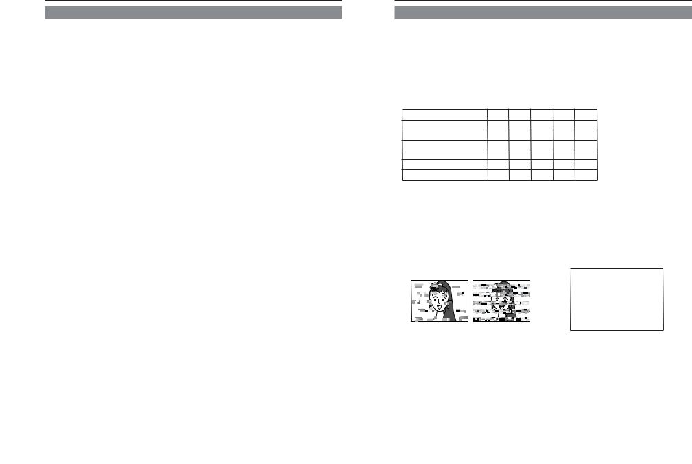
Head cleaning |
● |
If dust adheres on the head, “HEAD CLEANING |
||
● |
Recording or playing back with a stained head |
REQUIRED!” will be displayed on the monitor |
||
when this unit plays a tape. |
||||
|
will result in block noise or disrupted |
sound. |
||
|
|
|||
|
Please perform regular head cleaning to main- |
|
||
|
tain superior image and sound quality. |
|
|
|
|
|
|
HEAD CLEANING REGUIRED! |
|
|
Block noise |
|
|
|
●For information on how to use the head cleaning tape and the relevant precautions, please refer to page 8, “Precautions on the use of cleaning
tape”.
6
7
INTRODUCTION Precautions on the use of cleaning tape
Please use cleaning tape produced by JVC.
Please follow the instructions below when using the cleaning tape.
1. The tape will run for 10 seconds in the PLAY mode. (Thereafter, it stops automatically and enters the STOP mode.)
•After loading the cleaning tape, press the PLAY button.
2. For a single cleaning session, use it up to 4 times.
3. Please refer to the following table as a guide for cleaning:
Memo:
1.Under low humidity conditions, (10% RH to 30% RH), please perform head cleaning at intervals of half of the following stated periods.
2.If M-DV80 is used immediately after cleaning, the VTR warning (“HEAD CLEANING REQUIRED!”) may disappear only after the tape has run for some time.
3.Please use the cleaning tape at room temperature (10˚C to 35˚C).
4.Instructions for using the cleaning tape are stated inside its case. The contents may be slightly different from those stated here.
Please follow the instructions in this manual.
Operating environment |
Low temperature |
Room temperature |
High temperature |
of the unit |
5˚C to 10˚C |
10˚C to 35˚C |
35˚C to 40˚C |
Guide for using |
1 to 2 times every |
1 to 2 times every |
1 to 2 times every |
cleaning tape |
5 hours |
20 to 30 hours |
5 hours |
Cassette tape |
|
|
This unit can record onto and playback standard |
||
DV and mini DV cassette tapes (for SP mode only). |
||
Please use the following JVC cassettes with the |
||
or the |
logos. |
|
● Standard DV cassettes |
● Mini DV cassettes |
|
LA-DV276 |
M-DV63PR0 |
|
LA-DV186 |
M-DV60 |
|
LA-DV124 |
M-DV30 |
|
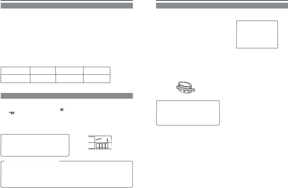
Erasure prevention
DV cassettes have a safety slide at the back to prevent accidental erasure.
●To prevent accidental erasure of important records, push the slide to the “SAVE” position.
●To record, push the slide to the “REC” position.
Slide
|
|
|
|
|
|
|
Memo |
|
REC |
|
|
● DVCAM cassettes can be recorded in DV format. |
|
||||
SAVE |
|
|
|||
|
Tapes recorded in DVCAM format can be played |
|
|
||
|
|
|
|
||
|
(SP Mode). |
|
|
|
|
● M-DV80 cassettes(Mini DV 80min tape) cannot be |
|
|
|
||
|
used with this unit. |
|
|
|
|
|
Precautions on the use of tape |
|
|
|
|
● Reverse sides of videotapes cannot be used. |
|
|
|
||
● Please store the tape only after it has been fully rewound, so as to avoid damaging the tape. |
|||||
● Please store the cassette in places low in humidity, well-ventilated and fungus-proof. |
|||||
● When a cassette is used repeatedly, noise may increase due to e.g., dropout, etc. hence affecting its |
|||||
|
performance. Please do not use dirty or damaged tapes as they will shorten the life span of the |
||||
|
rotation head. |
|
|
|
|
|
Condensation |
|
|
● |
When this unit is moved from a cold to a warm |
● |
When condensation occurs, the monitor displays |
|
place abruptly, the vapor in the warm air will come |
|
the following warning: |
|
into contact with the head drum or the tape |
|
|
|
guides. When chilled, the vapor turns into drop- |
|
|
|
lets of water. This state is known as condensa- |
|
|
|
tion. When condensation occurs, the videotape |
|
CONDENSATION ON DRUM |
|
will adhere to the head drum or the tape guides |
|
|
|
|
|
|
|
and will be damaged. |
|
|
●Condensation occurs on this unit in the following circumstances:
• It is moved abruptly from a cold place to a warm |
|
To remedy, leave the unit with the power ON and |
|||
|
wait until the WARNING indicator disappears. |
||||
place. |
|
||||
|
|
||||
• It is used in a room immediately after the heater |
|
|
|||
has been turned on, or when cold breeze from |
● |
Prevention of condensation |
|||
an air-conditioner blows onto it. |
|
When transporting the BR-DV3000 from a cold |
|||
|
|
|
|
|
|
• It is used at a place of high humidity. |
|
to a warmer place abruptly, first take out the cas- |
|||
|
|
|
Head drum |
|
sette.Then place the BR-DV3000 in a plastic bag |
|
|
|
|
|
and seal it before transporting the camera. Leave |
|
|
|
|
|
the BR-DV3000 in the sealed plastic bag until |
|
|
|
|
|
the camera has the same temperature as the sur- |
|
|
|
|
|
roundings. This will prevent condensation. |
|
|
Videotape |
|
|
|
|
|
|
|
||
When a cassette tape is loaded, please do not |
|
|
|||
transport e.g., from an external cold place to a |
|
|
|||
warm room thereby subjecting the unit to dras- |
|
|
|||
tic temperature changes. |
|
|
|||
After moving the unit, please do not use it until |
|
|
|||
the innards are stabilized. |
|
|
|||
8 |
9 |
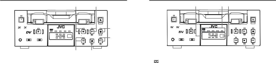
NAMES AND FUNCTIONS |
– Front panel – |
OF VARIOUS PARTS |
OPERATE |
|
|
1 |
|
|
Mini |
|
A.DUB |
PROFESSIONAL |
|
|
MIC |
REMOTE SEL. |
INPUT SEL. |
|
SERIAL |
LINE |
|
9PIN WIRELESS |
DV Y/C |
2 |
|
|
|
|
EJECT |
|
|
MENIU |
REC |
PLAY |
PAUSE |
DVCAM NTSC PAL REC INH. |
|
|
CH-1/3 |
|
SET |
REW |
STOP |
FF |
CH-2/4 |
|
|
BR-DV3000 |
|
|
4 3
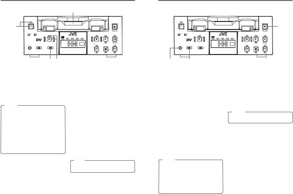
1 |
[OPERATE] Operate button/LED |
|
●Press this button to turn on the power and operate the unit. (Operate ON)
Press this button again to turn off the power. (Operate OFF)
●The OPERATE LED lights up as follows.
Operate ON |
: the LED lights up green |
Operate OFF |
: the LED lights up red |
VTR error |
: the LED blinks in red |
Memo ● When the DC IN MODE item of the SYSTEM menu is set to “OPE ON” and power is supplied to the 1 [DC IN] terminal located at the rear panel, the unit goes into the OPERATE ON state even if this button is not pressed.
● Even when the power has been turned off with this button, a small amount of electricity will still be channeled into the unit.Therefore, if the unit is not going to be used for a long period of time, please remove the AC adapter to reduce energy consumption.
2 |
Cassette slot |
|
●Load a cassette into or unload it from the slot. Please insert a standard DV or a mini DV cas-
sette. Page 30 ● When the unit is in the OPERATE OFF state and if a cassette is loaded, it goes into the ON state.
3 |
[A. DUB] Audio dubbing button/LED |
|||
|
||||
|
● Press this button for audio dubbing (after-re- |
|||
|
cording). |
|||
|
For audio dubbing, set the AUDIO MODE item |
|||
|
of the AUDIO/VIDEO menu to “32K”. |
|||
|
Sound produced by the 6 MIC terminal or |
|||
|
the |
9 |
AUDIO IN terminal at the rear panel is |
|
|
|
|
||
|
recorded on CH3 and CH4 channels. |
|||
|
● During audio dubbing, the A. DUB LED lights |
|||
|
up red. |
|||
|
● If the INPUT SEL switch is set at DV, audio |
|||
|
dubbing is not possible. |
|||
|
Page 39, “Audio dubbing” |
|||
4 |
[INPUT SEL] Input video signal se- |
|||
|
||||
|
lection switch |
|||
|
● Select the video signal input with this switch. |
|||
|
Y/C |
: YC separate video signals from the Y/ |
||
|
|
|
|
C IN terminal |
|
LINE : composite video signals from the LINE |
|||
|
|
|
|
IN terminal |
|
DV |
|
: DV signals from the DV IN/OUT termi- |
|
|
|
|
|
nal (IEEE1394) |
|
Note |
|
|
|
|
During recording, please do not manipulate |
|||
|
this switch. Even if you do, it will not work. |
|||
10
OPERATE
|
Mini |
A.DUB |
PROFESSIONAL |
|
|
MIC |
REMOTE SEL. |
INPUT SEL. |
|
SERIAL |
LINE |
|
9PIN WIRELESS |
DV Y/C |
|
|
EJECT |
|
|
7 |
|
|
MENIU |
REC |
PLAY |
PAUSE |
DVCAM NTSC PAL REC INH. |
|
|
CH-1/3 |
|
SET |
REW |
STOP |
FF |
CH-2/4 |
|
|
BR-DV3000 |
|
|
6 |
5 |
5 |
[REMOTE SEL.] Remote select |
|||
|
switch |
|
|
|
|
Use this switch to select the remote controller |
|||
|
type. |
|
|
|
|
9 PIN |
: Select this to use the RS-422A- |
||
|
|
compatible editing remote con- |
||
|
|
troller (RM-G820) that connects |
||
|
|
to the |
4 |
9 PIN REMOTE termi- |
|
|
|
||
|
|
nal located at the rear panel. |
||
|
|
Please use this unit as a player. |
||
|
|
* This setting is valid only when |
||
|
|
the REMOTE item of the RE- |
||
|
|
MOTE menu is set to ON. |
||
|
SERIAL |
: Select this to use the serial re- |
||
|
|
mote controller (RM-G30) that |
||
|
|
connects to the 3SERIAL RE- |
||
|
|
MOTE terminal located at the |
||
|
|
rear panel. |
||
|
|
* This setting is valid only when |
||
|
|
the REMOTE item of the RE- |
||
|
|
MOTE menu is set to ON. |
||
|
WIRELESS |
: Select this to use the provided |
||
|
|
wireless remote controller. |
||
Memo ● When 9 PIN or SERIAL is selected, the buttons on the unit you wish to render operable can be selected from the LOCAL FUNCTION item of the REMOTE menu. Page 59
● During OPERATION LOCK, this switch will not be effective. ● Control via the DV IN/OUT terminal is possible (ie unaffected by the switch setting).
6 |
[MIC] Microphone input terminal |
|
|
|
This is the mini jack for monaural microphone |
|
input. When this terminal is connected to a mi- |
|
crophone, sound input via the AUDIO IN termi- |
|
nal located on the rear panel is not recorded. |
|
Sound from this terminal is recorded on CH1/ |
|
CH2 in the RECORD mode and CH3/CH4 in |
|
the AUDIO DUBBING mode. |
7 |
[EJECT] Eject button |
|
|
|
● Press this button to eject the cassette. |
|
Memo |
It takes about 6 seconds for the cassette to |
|
be ejected. |
|
|
● If no cassette is loaded and this button is |
|
pressed for at least 2 seconds, a menu will be |
|
displayed on the monitor connected to the |
|
VIDEO LINE OUT or Y/C OUT terminal. |
|
● When the menu is displayed, pressing this |
|
button will resume the usual screen. |
|
Page 54, “Setting the menu” |
11
NAMES AND FUNCTIONS |
– Front panel |
|
|
OF VARIOUS PARTS |
– (continued) |
||
|
8 |
9 |
|
OPERATE
|
Mini |
A.DUB |
PROFESSIONAL |
|
|
MIC |
REMOTE SEL. |
INPUT SEL. |
|
SERIAL |
LINE |
|
9PIN WIRELESS |
DV Y/C |
8 |
[REC] Record button/LED |
|
|
|
EJECT |
|
|
|
MENIU |
|
REC |
PLAY |
PAUSE |
0 |
DVCAM NTSC PAL REC INH. |
|
|
|
|
|
|
|
CH-1/3 |
|
SET |
|
REW |
STOP |
FF |
! |
CH-2/4 |
|
|
|
BR-DV3000 |
|
|
|
#@
! [FF] Fast forward button/LED
●Hold down this button and press the 9 PLAY button to start recording. During recording, the LED lights up red.
●Hold down this button and press the 0PAUSE button to pause the recording.
●When this button is pressed during recording, an index signal is recorded on the tape (valid when the INDEX WRITE item in the SYSTEM menu is set to ON).
●When the unit is in the STOP mode, press this button to execute fast-forward winding of the tape.
●When the unit is in the PLAYBACK or STILL mode, press this button to execute fast-for- ward playback. The Fast-forward playback speed changes in the following sequence each time this button is pressed:
X20¥X5¥X9¥X20...
9
● When recording is stopped, the time code generator value can be verified by holding this button down. If the TC DUPLICATE menu item is set to AUTO or NON DROP, EE signals of the DV Input time code and Date/Time can be verified.
[PLAY] Play button/LED
● Press this button to start playing back a tape. During playback, the LED lights up green. ● When recording is paused, press this button to resume recording.
● When the menu is displayed, use this button to select the menu items or setting values.
In the DVCAM mode, the maximum speed is 15X. ● During fast-forward winding or fast-forward playback, the LED lights up green. ● When the menu is displayed, use this button to display selected menu items.
● When setting up the date, time or time code, use this button to select the data segment.
@ [STOP] Stop button/LED
● Press this button to stop operation. (of rewind, playback, etc.) ● When the menu is displayed, use this button to select the menu items or setting values.
# [REW] Rewind button/LED
0
[PAUSE] Pause button/LED ● During recording, press this button to pause it. During playback or STOP mode, press this button to enter the STILL mode. When recording is paused or when the unit is in the STILL mode, the LED lights up green. ● If this button is pressed simultaneously with the A.DUB button in the STILL mode, the Audio Dubbing Pause mode will be engaged.
● When the menu is displayed, use this button to confirm the menu items or setting values.
●When the unit is in the STOP mode, press this button to rewind the tape.
●When the unit is in the PLAYBACK or STILL mode, press this button to execute reverse playback. The Reverse playback speed changes in the following sequence each time this button is pressed:
X20¥X5¥X9¥X20... In the DVCAM mode, the maximum speed is 15X. ● During rewinding or reverse playback, the LED lights up green.
● When the menu is displayed, press this button to return to the previous screen. When setting up the date, time or time code, use this button to select the data segment.
12
%
OPERATE
|
Mini |
A.DUB |
PROFESSIONAL |
|
|
MIC |
REMOTE SEL. |
INPUT SEL. |
|
SERIAL |
LINE |
|
9PIN WIRELESS |
DV Y/C |
$ ^ |
|
|
|
|
EJECT |
|
|
MENIU |
REC |
PLAY |
PAUSE |
DVCAM NTSC PAL REC INH. |
|
|
CH-1/3 |
|
SET |
REW |
STOP |
FF |
CH-2/4 |
|
|
BR-DV3000 |
|
|
$
Indicator
|
: When a cassette is loaded, the LED |
|
|
lights up green. (Likewise when the |
|
|
unit is in the OPERATE OFF state.) |
|
|
When a cassette is being loaded |
|
|
or ejected, the LED blinks. |
|
DVCAM |
: When the unit plays back a tape re- |
|
|
corded in the DVCAM format, the |
|
|
LED lights up green. |
|
NTSC |
: The LED lights up green in the fol- |
|
|
lowing cases: |
|
|
• In the composite video orYC video |
|
|
signal input mode and the |
2 |
|
NTSC/PAL switch located at the |
|
|
rear panel is set as “NTSC”. |
|
|
• A tape recorded with NTSC sig- |
|
|
nals is played back. |
|
|
• When NTSC signals are input |
|
|
while the INPUT SEL switch is set |
|
|
at DV. |
|
PAL |
: The LED lights up green in the fol- |
|
|
lowing cases: |
|
|
• In the composite video orYC video |
|
|
signal input mode and the |
2 |
|
NTSC/PAL switch located at the |
|
|
rear panel is set as “PAL”. |
|
|
• A tape recorded with PAL signals |
|
|
is played back. |
|
|
• When PAL signals are input while |
|
|
the INPUT SEL switch is set at DV. |
|
REC INH : The LED lights up red for about 5 |
||
|
seconds when the unit is set to the |
|
|
recording mode but fails to record. |
|
|
E.g. when the rear slide of the cas- |
|
|
sette is pushed to the “SAVE” posi- |
|
|
tion. |
|
% Audio indicator
This indicator allows the user to check the availability of audio signals. 3 indicators each are available to CH1/3 and Ch2/4.
^ Sensor for wireless remote controller
When using the provided wireless remote controller, please point it to this sensor. ( Page 25, “USING THE WIRELESS REMOTE CONTROLLER”
13

NAMES AND FUNCTIONS |
– Rear panel – |
OF VARIOUS PARTS |
DV IN/OUT |
|
|
|
|
AUDIO |
|
LINE |
VIDEO |
Y/C |
CH 1/3 |
CH 2/4 |
|
||
|
|
|
IN |
|
|
|
|
REMOTE |
|
DC12V |
|
|
|
|
OUT |
|
NTSC/PAL |
1 |
|
|
1 |
DC power input terminal (2P) |
|
|
|
This is used for DC12V input. It connects the |
|
DC power cord of the provided AC adapter. |
|
Memo |
●When power is supplied to this terminal, the OPERATE indicator located at the front panel lights up. (The LED lights up red when the OPERATE indicator is OFF.)
●Setting this unit to OPERATE ON, OPERATE OFF or PLAY mode when the power is supplied to this terminal can be done by making the appropriate selections from the DC IN MODE item in the SYSTEM menu.
2 |
[NTSC/PAL] NTSC/PAL signal se- |
|
|
lection switch |
|
|
Use this switch to select NTSC or PAL as the |
|
|
signal system. Use it to make a selection when |
|
|
composite video signals or YC separate video |
|
|
signals are input. |
|
|
NTSC |
: Use this setting for NTSC signal input. |
|
|
The NTSC indicator on the front panel |
|
|
lights up. |
|
PAL |
: Use this setting for PAL signal input. |
|
|
The PAL indicator on the front panel |
|
|
lights up. |
9PIN |
SERIAL |
NTSC PAL |
4 |
3 |
3 |
2 |
|
[SERIAL REMOTE] serial remote |
||
|
|
terminal (mini jack) |
|
|
|
Connect this terminal to the serial remote con- |
|
|
|
troller RM-G30, which is available separately. |
|
|
|
To control this unit via this terminal, please set |
|
|
|
it up as follows. |
|
●Set the REMOTE item of the REMOTE menu to ON.
●Set the [REMOTE SEL.] switch on the front panel to “SERIAL”.
Memo To use this terminal as the FOOT switch input terminal, please set the FOOTSW item of the REMOTE (2/2) menu. Page 60
4 |
[9 PIN REMOTE] 9-pin remote ter- |
|
minal (D-SUB) |
|
Use this terminal to connect to the RS-422A- |
|
compatible editing remote controller (RM-G820). |
|
Please use this unit as a player. To control this |
|
unit with this terminal, please set it up as fol- |
|
lows: |
|
● Set the REMOTE item of the REMOTE |
|
menu to ON. |
|
● Set the [REMOTE SEL.] switch on the front |
|
panel to “9 PIN”. |
Memo
●For playback or DV signal input, signals are determined automatically and not affected by the status of this switch.
●Please turn the unit to OPERATE OFF before using this switch. If switching is performed when the VTR is in the OPERATE ON mode, the VTR will automatically go into the OFF mode before engaging the ON mode.
●It cannot be used for NTSC/PAL conversion.
! |
6 |
5 |
DV IN/OUT
AUDIO |
CH 2/4 |
CH 1/3 |
9 0
LINE |
VIDEO |
Y/C |
|
||
|
|
IN |
|
|
OUT |
87
5 |
[VIDEO Y/C IN] Video Y/C input |
|
terminal (4P) |
|
This is the input terminal for YC separate video signals. |
|
● To input video signals from this terminal, |
|
set the [INPUT SEL.] switch on the front |
|
panel to “Y/C”. |
|
● When Wide discriminating signals are in- |
|
put, ID signals for Wide discriminating sig- |
6 |
nals are recorded. |
[VIDEO LINE IN] Video line input |
|
|
terminal (RCA) |
|
This is the input terminal for composite video |
|
signals. |
|
● To input video signals from this terminal, |
|
set the [INPUT SEL.] switch on the front |
7 |
panel to “LINE”. |
[VIDEO Y/C OUT] Video Y/C output |
|
|
terminal (4P) |
|
This is the output terminal for YC separate video |
8 |
signals. |
[VIDEO LINE OUT] Video line out- |
|
|
put terminal (RCA) |
|
This is the output terminal for composite video signals. |
|
When tapes recorded with Wide discriminating |
|
signals are played, ID signals for discriminating |
|
signals are output. |
|
Memo |
●Besides video signals, the following signals from the [VIDEO Y/C OUT] terminal and [VIDEO LINE OUT] terminal are displayed on-screen.
•Menu screen signals
•Character display of date, time or operation modes (Status screen)
By pressing the DISPLAY button on the wireless remote controller or by setting the DISPLAY item in the DISPLAY menu, the user can choose to turn the status display on/off.
●The SETUP item of the AUDIO/VIDEO menu can be set to determine whether setup will be added to the signals of [VIDEO Y/C OUT] terminal and [VIDEO LINE OUT] terminal. (NTSC only).
|
REMOTE |
DC12V |
|
|
|
|
|
NTSC/PAL |
9PIN |
SERIAL |
NTSC PAL |
9 |
[AUDIO IN] Audio input terminal |
|
(RCA 2) |
|
This is the audio signal (analogue) input termi- |
|
nal. |
|
For audio dubbing, sounds from the CH1/3 ter- |
|
minal are recorded on the CH3 channel while |
|
those from the CH2/4 channel are recorded on |
|
the CH4 channel. |
|
Memo |
When the MIC terminal on the front panel is connected |
|
to a microphone, sounds from this terminal will not |
|
be recorded. |
|
0 |
[AUDIO OUT] Audio output terminal |
|
(RCA 2) |
|
This is the audio signal (analogue) output ter- |
|
minal. |
|
Memo |
●The audio channel to play back tapes recorded in the 32k mode can be selected with the OUT SELECT button on the wireless remote controller or by setting the AUDIO OUT SEL. item of the AUDIO/VIDEO menu.
●The output level of the playback audio can be selected with the OUT LEVEL button of the wireless remote controller or by setting the AUDIO OUT LEVEL item of the AUDIO/VIDEO menu (NORMAL
or ATT).
! [DV IN/OUT] DV input/output terminal
This is the input/output terminal for digital signals of IEEE1394 standard. It is connected to video devices with DV terminals.
●To input signals from this terminal, please set the [INPUT SEL.] switch on the front panel to “DV”.
●Signals from this terminal are output regard-
less of the INPUT SEL. switch setting.
14
15

NAMES AND FUNCTIONS |
– Wireless remote controller – |
OF VARIOUS PARTS |
|
2 4 5 |
|
|
||
|
DISPLAY |
|
|
|
1 |
|
BARS |
STILL |
BLANK |
|
|
3 |
MODE |
|
|
||
|
|
|
AUDIO |
|
|
|
|
|
|
|
|
|
MENU |
SEARCH+ |
|
MUTING |
|
9 |
|
|
|
|
6 |
|
|
|
OUT SEL. |
7 |
|
|
|
SET |
|
|
|
SET |
|
SEARCH– |
|
OUT LEV. |
|
BUTTON |
|
|
|
|
8 |
|
|
|
|
|
|
0 |
A.DUB |
PAUSE |
|
REC |
@ |
|
|
|
|
||
! |
F.REV |
PLAY |
F.ADV |
# |
|
|
|
|
|||
$ |
|
|
|
|
& |
|
REW |
|
|
FF |
|
|
|
STOP |
|
|
|
^ |
INDEX– |
|
|
INDEX+ |
% |
|
|
|
|
||
REMOTE CONTROL UNIT
RM-G3000
1 |
OPERATE button f |
|
|
|
Press this button to turn on the power of the |
|
unit. (OPERATE ON) |
|
Press this button again to turn off the power. |
|
(OPERATE OFF) |
2 |
DISPLAY button |
|
|
|
Use this button to turn on/off, the on-screen (e.g. |
|
status screen) display on the monitor connected |
|
to the VIDEO LINE OUT terminal and Y/C OUT |
|
terminal. Each time this button is pressed, the |
|
display mode changes in the following se- |
|
quence: ON (always display) ¥AUTO (display |
|
when switching mode) ¥ OFF. |
|
Page 18, “On-screen display” |
3 |
BARS button |
|
|
|
When this button is pressed in the Stop or REC- |
|
Pause mode, the color bar of the built in signal |
|
generator will be output. When it is pressed |
|
again, the screen returns to the usual display. |
|
During DV signal input, the color bar will not be |
|
output. |
|
Note |
Please do not use it as the standard signal |
|
because the signals are simplified. |
|
4 |
STILL MODE button |
||
|
|||
|
Use this button to select images in the STILL |
||
|
mode. |
|
|
|
When the unit is in the STILL mode, press this |
||
|
button to toggle images in the following se- |
||
|
quence. |
|
|
|
Field image (1st/2nd alternate still) ¥ 1st field |
||
|
image ¥ 2nd field image ¥ frame image |
||
5 |
BLANK button |
||
|
|||
|
When the unit enters the STOP mode, press |
||
|
this button to begin a blank search. Once it finds |
||
|
a blank part of the tape, it will enter the STILL |
||
|
mode. Page 47 |
||
6 |
AUDIO MUTING button |
||
|
|||
|
During playback, press this button to mute the |
||
|
audio output. Press this button again to re-en- |
||
|
able audio output. |
|
|
7 |
AUDIO OUT SEL. button |
||
|
|||
|
When playing back tapes recorded in the 32k |
||
|
mode, use this button to select the audio chan- |
||
|
nel that allows output from the AUDIO OUT ter- |
||
|
minal. |
|
|
|
CH1/2 ¥ CH3/4 ¥ MIX |
||
8 |
AUDIO OUT LEV button |
||
|
|||
|
Use this button to switch the standard level |
||
|
of the playback or EE audio output (NOR- |
||
|
MAL or ATT). When it is set to ATT, the out- |
||
|
put level is reduced by 8dB. |
||
9 |
Buttons related to menu setting and |
||
|
variable speed playback |
||
|
MENU button |
|
|
|
When the unit enters the STOP mode and |
||
|
this button is pressed, a menu will be dis- |
||
|
played on the monitor connected to the |
||
|
VIDEO LINE OUT or Y/C OUT terminal. |
||
|
When the menu is displayed, press this but- |
||
|
ton to return to the usual screen display. |
||
|
SEARCH+ / |
|
button |
|
|
||
•During playback, STILL mode or variable speed playback in the forward direction, press this button to speed up playback.
•During reverse playback or variable speed playback in the reverse direction, press this
button to slow down the playback speed. ( page 46) • When the menu is displayed, use this button to select the menu items or setting values.
SEARCH– / |
|
button |
|
•During playback, STILL mode or variable speed playback in the forward direction, press this button to slow down the playback speed.
•During reverse playback or variable speed
playback in the reverse direction, press this button to speed up the playback speed. ( page 46)
•When the menu is displayed, use this button to select the menu items or setting values.
P / button
•During reverse payback/ variable-speed playback, press this button to execute forward playback.
•When the menu is displayed, use this button to display the selected menu items. During date/time or time code setup, press this button to move the cursor to the right.
p / |
|
button |
|
•During forward playback/ variable-speed playback, press this button to execute reverse playback.
•When the menu is displayed, press this button to display the previous menu. During date/time or time code setup, press this button to move the cursor to the left.
SET button
During menu display, press this button to confirm the menu items or setting values.
0 |
A. DUB button |
|
|
|
Press this button to perform audio dubbing (af- |
|
ter-recording). Page 39, “Audio dubbing” |
! |
PAUSE button |
|
|
|
During recording, audio dubbing or playback, |
|
press this button to pause recording or enter |
|
the STILL mode. |
|
If this button is pressed in the STOP mode, the |
|
STILL mode will be engaged. |
@ |
REC button |
|
|
|
● Hold down this button and press the PLAY |
|
button to begin recording. |
|
● During recording, press this button to record |
|
an index on the tape (when the INDEX WRITE |
|
item of the SYSTEM menu is set to ON). |
|
● When the unit enters the STOP mode, hold- |
|
ing this button down will enable you to check |
|
the value of the time code generator. |
# |
F. ADV button |
||
|
|||
|
Each time this button is pressed in the STILL |
||
|
mode, the image is advanced one frame. When |
||
|
holding down this button, the image is advanced |
||
|
continuously frame by frame. |
||
$ |
F. REV button |
||
|
|||
|
Each time this button is pressed in the STILL |
||
|
mode, the image is reversed one frame. When |
||
|
holding down this button, the image is reversed |
||
|
continuously frame by frame. |
||
|
Memo |
|
|
The image of frame advance playback or frame re- |
|||
verse playback can be selected with the STL/F.ADV |
|||
MODE item of the SYSTEM menu or the STILL |
|||
MODE button on the wireless remote controller. |
|||
% |
INDEX+ button |
||
|
|||
|
Press this button to perform an index search in |
||
|
the forward direction. Page 47 |
||
^ |
INDEX– button |
||
|
|||
|
Press this button to perform an index search in |
||
|
the reverse direction. Page 47 |
||
& |
Operation buttons |
||
|
|||
|
PLAY( |
|
) button |
|
|
||
•Press this button to play back.
•Press this button to resume recording from the PAUSE mode.
FF( ) button
•Press this button to fast-forward the tape when the unit is in the STOP mode.
•Press this button to execute fast-forward playback in the PLAY or STILL mode.
REW( ) button
•Press this button to rewind the tape when the unit is in the STOP mode.
•Press this button to execute reverse playback in the PLAY or STILL mode.
STOP( ) button
•Press this button to stop the tape.
16 |
17 |
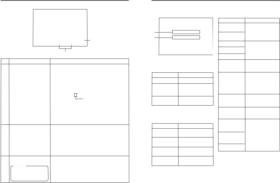
ON-SCREEN DISPLAY |
– Regarding on-screen display – |
|||||||||
Besides E-E images and playback images, the monitor connected to the VIDEO LINE OUT terminal and Y/ |
||||||||||
C OUT terminal provides the following on-screen information. |
|
|
|
|
|
|||||
Wireless remote controller |
Display (1/2) menu screen |
|
||||||||
|
|
|
|
|
|
|||||
|
|
|
|
|
|
– – – D |
I S P L A Y [ 1 |
/ 2 ] |
– – – |
|
|
|
|
|
|
D I P L A Y |
P O S I . |
O N |
|
Set at ON |
|
|
DISPLAY |
|
|
|
C O U N T E R |
L OW E R - R |
or AUTO |
|||
DISPLAY |
|
|
|
T I M E |
C O D E |
O N |
|
|||
|
STILL |
|
|
V T R |
MO D E |
|
O N |
|
|
|
BUTTON |
|
|
|
T A P E |
R E M A I N |
O F F |
|
|||
BARS |
MODE BLANK |
|
|
|
||||||
|
|
|
|
|
T I M E |
D A T E |
D A T E + T M |
|
||
|
|
|
AUDIO |
|
A U D I |
O I N F O . |
C H + R A T E |
|
||
|
MENU |
SEARCH+ |
MUTING |
|
N E X T |
P A G E |
|
|
|
|
MENU |
|
|
|
|
P A G E |
B A C K |
|
|
|
|
|
|
|
|
|
|
|
|
|
|
|
BUTTON |
|
|
OUT SEL. |
|
|
|
|
|
|
|
|
|
SET |
|
|
|
|
|
|
|
|
|
|
SEARCH– |
OUT LEV. |
|
|
|
|
|
|
|
|
A.DUB |
PAUSE |
REC |
|
|
|
|
|
|
|
On-screen display |
Contents |
Status display |
It displays the setting status of date/ |
|
time, time code and VTR operation |
|
mode. |
Event display |
It displays the operating status of the |
|
blank search, index recording/search, |
|
or the wireless remote control. |
Alarm display |
It displays alarm messages upon op- |
|
eration errors or if the unit is in a poor |
|
state for operation. |
Warning display |
It displays warning messages with er- |
|
ror codes in the event of VTR anoma- |
|
lies. ( Page 66) |
Menu display |
It displays the menu setting screen. |
|
( Page 53) |
|
Method |
Main unit |
|
Set the DISPLAY item of the DISPLAY |
|
(1/2) menu as follows: |
|
ON |
: Always display. Depending |
|
on the items, Event and |
|
Alarm displays are shown for |
|
about 3 seconds. |
AUTO |
: It displays for about 4 sec- |
|
onds after switching between |
|
modes. |
OFF |
: No on-screen display. |
Remote controller |
|
The display can be turned ON/OFF |
|
with the DISPLAY button. Each time |
|
the DISPLAY button is pressed, the |
|
display mode changes in the follow- |
|
ing sequence: ON (Always display) |
|
¥AUTO ¥ OFF. |
|
*The settings for the DISPLAY menu |
|
items will also change accordingly. |
|
It is displayed automatically when |
|
anomalies happen. |
|
Main unit |
|
If no cassette is loaded and the EJECT |
|
button is pressed for at least 2 sec- |
|
onds, the menu will be displayed. |
|
Remote controller |
|
If the unit is in the STOP mode and |
|
the MENU button is pressed, the menu |
|
screen will be displayed. |
|
ON-SCREEN DISPLAY – Status display – |
|
Status display: It displays the current settings and operating status. |
|
1 |
|
3 2 K C H – 1 / 2 |
S P 0 0 0 m i n |
|
2 |
|
0 |
4 |
/ 0 1 |
/ 0 2 |
|
S T A N D B Y - O F F |
||
|
|
1 1 |
: 2 0 |
: 0 0 |
T C R |
0 2 |
: 0 0 |
: 0 0 : 0 0 |
||
|
|
|
||||||||
No. |
Item |
|
|
|
|
|
|
|
Content |
|
1 |
Sampling frequency/audio |
|
output CH |
|
Memo |
|
If the time code display position |
|
is set to the upper left, this item |
|
will be displayed on the lower |
|
right. |
2 |
Date/time |
|
|
|
Memo |
|
If the display position of the time |
|
code is set to the lower left, this |
|
item will be displayed on the |
|
lower right. |
•Sampling frequency
During recording, the setting value of the AUDIO MODE item of the AUDIO/VIDEO menu is displayed (32k or 48k).
During playback, the sampling frequency of the sound recorded on the tape is displayed (32k, 48k, 44.1k).
During DV signal input, the sampling frequency of the sound input is displayed.
•A.LOCK
Lights up when the video and audio sampling clocks (at 48kHz) are synchronized in the PLAY mode. Lights up in the RECORDING mode and EE mode. Does not light up when the sampling rate is 32kHz or 44.1 kHz.
•Audio output channel
During recording, the audio channel recorded on the tape is displayed.
During playback, the audio channel output from the AUDIO OUT terminal is displayed (CH1/2, CH3/4, MIX). (only in 32k mode)
•The AUDIO INFO item of the DISPLAY menu can be set to activate/deactivate the display.
•It displays the date (MM/DD/YY) and time (HR:MM:SS).
•When the unit is in the RECORDING or STOP mode, it displays the data of the built-in clock.
•During playback, fast forward or rewind, the data recorded on the tape is displayed.
•During DV signal recording, the data from the DV terminal is displayed. If the REC button is pressed in the STOP mode, the input data from the DV terminal will be displayed.
•The style for displaying the date and time can be selected from the DATE STYLE and TIME STYLE items of the DISPLAY menu.
•The TIME/DATE setting of the DISPLAY menu can be set to turn on/off the date and time display or to select the style.
•When the data/time is not set, “– –” will be displayed.
If a tape with no date and time data is played, "– –" will be displayed.
18
19
ON-SCREEN DISPLAY |
– Status display – |
(continued) |
||
3 2 K C H – 1 / 2 |
S P 0 0 0 m i n |
|
5 |
|
|
|
|||
0 4 |
/ 0 1 |
/ 0 2 |
|
S T A N D B Y |
- |
O F F |
4 |
||
1 1 |
: 2 0 |
: 0 0 |
T C R |
0 2 |
: 0 0 |
: 0 0 |
: 0 0 |
|
|
|
|
|
|
3 |
|
|
|
|
|
No. |
Item |
3 |
Time code |
|
4 |
VTR operation mode |
|
5 |
Remaining tape |
|
|
|
Memo |
|
If the display position of the time |
|
code is set to the upper right, |
|
this item will be displayed on the |
|
lower right |
Content
•It displays the time codes (hour, minute, second and frame).
During playback, the time codes recorded on the tape are displayed.
TCR |
: time code reader data |
TCG |
: time code generator data |
DTCG : time code data input from a DV IN terminal |
|
•The symbols for the second and frame differ according to the framing modes. (NTSC only)
00 |
: 00 |
: 00 |
: 00 |
¥dot (.) is used for a dropped frame.
colon (:) is used for a non-dropped frame.
•The time code display position can be set via the COUNTER POSI. item of the DISPLAY menu.
•The TIME CODE item can be set to turn on/off the time code display.
•The user’s bit is not displayed.
It displays the VTR operation modes, including: PLAY, EJECT, FF, REW, STANDBY-ON, STANDBY-OFF, STILL, REC, REC PAUSE, A. DUB, A. DUB PAUSE, SHTL (shuttle search), JOG (F.ADV, R.ADV), BLANK SRH (blank search), NO CASSETTE (cassette not loaded), OPERATE OFF.
When SHTL or JOG is displayed, the speed will also be displayed at the same time.
•The VTR MODE item of the DISPLAY menu can be set to turn on/off the VTR operation mode display.
It displays the remaining tape duration (minutes). If it is not identified, “ – – – ” is displayed.
•The TAPE REMAIN item in the DISPLAY menu can be set to turn on/off the remaining tape duration display.
•The SP display disappears when the DVCAM cassette is being played back.
•Please use the remaining tape time as a gauge.
ON-SCREEN DISPLAY – Event display – |
|
Event display |
: When a specific function is in activation or when the operation status is |
|
changed with the remote controller, etc, the events will be displayed at |
|
the positions shown below. |
3 2 K |
C H – 1 |
/ 2 |
|
S P |
0 0 0 m i n |
||
A |
|
|
B L A N K |
S E A R C H |
|
||
B |
|
|
I N D E X |
D E T E C T E D |
|
||
0 4 |
/ |
0 1 |
/ 0 2 |
|
|
S T A N D B Y - O F F |
|
1 1 |
: |
2 0 |
: 0 0 |
T C R |
0 2 : 0 0 |
: 0 0 : 0 0 |
|
Display at position A
...Operation in progress
Display BLANK SEARCH INDEX + 1
INDEX MARK
Contents Blank search in progress.
Index search in progress. The number indicates the index search position.
When an index is written on the tape during recording.
Display at position B
...Display for about 3 seconds
Display |
Contents |
INDEX DETECTED |
Index is found during an in- |
|
dex repeat operation. |
VIDEO END |
Video end is found during a |
DETECTED |
video end repeat operation. |
AUDIO MUTING |
Audio is muted with the re- |
ON |
mote controller. |
AUDIO MUTING |
Audio is de-muted with the |
OFF |
remote controller. |
Display |
Contents |
AUDIO OUT |
The standard level of the |
LEVEL NORM |
playback or EE audio level is |
AUDIO OUT |
set to NORMAL or ATT with |
the remote controller. |
|
LEVEL ATT |
|
AUDIO OUT CH-1/2 |
The playback audio channel is |
AUDIO OUT CH-3/4 |
set to CH1/2, CH3/4 or MIX |
with the remote controller. |
|
AUDIO OUT MIX |
|
DISPLAY ON
DISPLAY AUTO
DISPLAY OFF
The on-screen display is turned on with the remote controller.
The on-screen display is set to AUTO with the remote controller. In the AUTO mode, the on-screen display is shown for about 4 seconds between mode switches.
The on-screen display is set to OFF with the remote controller.
FIELD STEP |
Field by field advance play- |
|
back is selected with the re- |
|
mote controller. |
1ST FIELD STILL
2ND FIELD STILL
FRAME STILL
When still or frame advance playback is selected with the remote controller, the type of still image is displayed.
•1st FIELD STILL
•2nd FIELD STILL
•FRAME STILL
20 |
21 |
 Loading...