


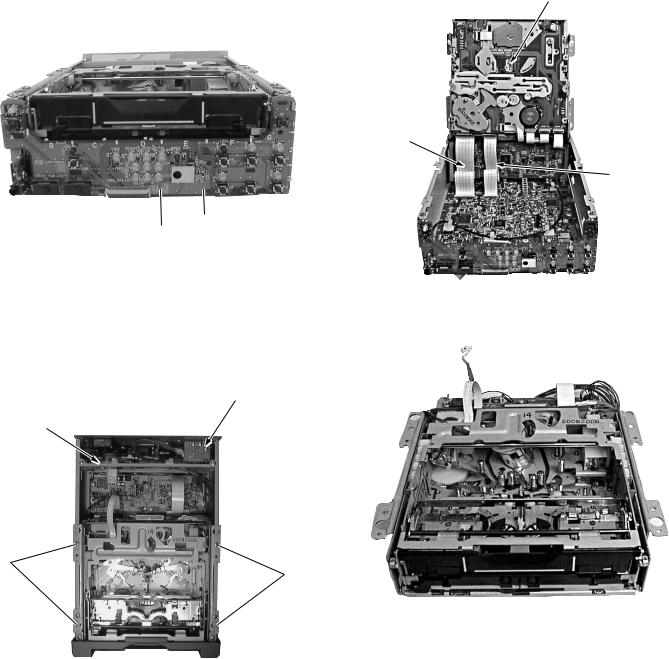
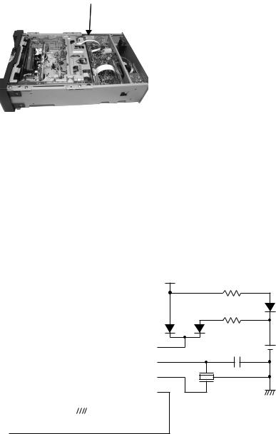
1.4HOW TO EXAMINE THE BOARDS
1.4.1 MAIN board assembly
(1)Remove the bottom cover to examine the B-side of the main board.
3
 Main board assembly
3
Fig. 1.4.1 (1)
(2)Remove the four screws 3 to examine the A-side.
(3)Remove the two screws 4 on the rear cover.
(4)Pull down the main board as shown in fig. 1.4.1 (3).
4
REAR COVER
Fig. 1.4.1 (2)
MAIN board assembly
Keep a distance to a minimum from the unit, because this FFC cable may be damaged.
Fig. 1.4.1 (3)
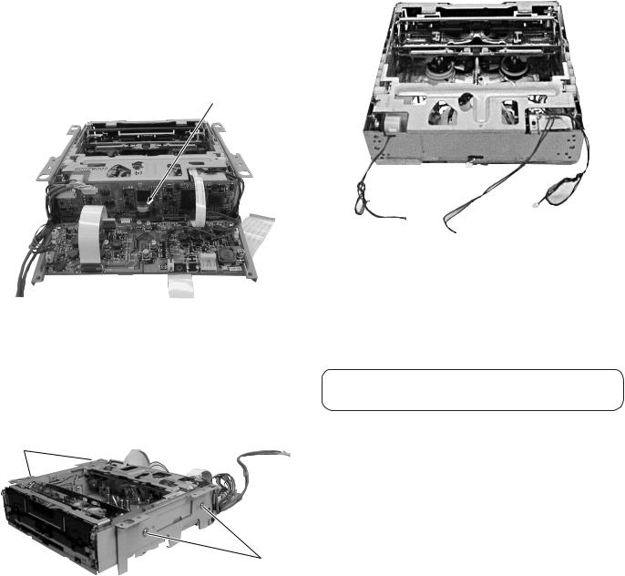
1.4.2 MDA/DC board assembly
(1)Remove the top cover to examine the A-side.
(2)To examine the B-side, pull down the main board as shown in Fig. 1.4.2 (2).
MDA/DC board |
DV/CPU board |
assembly |
assembly |
Fig. 1.4.2 (1)
MDA/DC board assembly
Fig. 1.4.2 (2)
1.4.3 DV/CPU board assembly
(1)Remove the top cover as shown in Fig. 1.4.2 (1) to examine the DV/CPU board.
1-3
1.4.4 FRONT board assembly |
|
(1) Remove the front panel to examine the front board. |
Mechanism unit |
|
(2)Remove the screw 5, and pull the board down to examine the B-side.
CN4002
CN4003
FRONT board
5assembly
Fig. 1.4.4
1.5HOW TO REMOVE THE MECHANISM UNIT
(1) Remove the four screws 6. |
Fig. 1.5.2 |
|
(2)Remove the front panel.
(3)Remove the CN111 connector on the MDA/DC board.
(4)Remove the wire that are attached to the DV CONN board.
DV CONN board
CN111
6
6
Fig. 1.5.3
Fig. 1.5.1
(5)Pull up the mechanism unit.
(6)Remove CN4002 and CN4003 (FFC cables connected to the main board).
1-4
1.6HOW TO REMOVE THE MECHANISM ASSEMBLY
To remove only the mechanism assembly from the mechanism unit.
(1)Remove the shield case on the DV/CPU board and remove the CN107 FPC wire from the drum assembly.
CN107
Fig. 1.6.1
(2)Remove the FFC wires that connects the mechanism board, which is mounted on the backs of the mechanism assembly, MDA/DC board, and the DV/CPU board.
(3)Remove the four screws 7 on the side.
(4)Remove the mechanism assembly as shown in Fig. 1.6.3.
7
7
Fig. 1.6.2
To: CN114 |
To: CN117 |
|
MDA/DC board |
||
|
||
MDA/DC board To: CN119 |
||
|
MDA/DC board |
|
|
Fig. 1.6.3 Mechanism assembly |
|
For instructions on disassembling each part of the mechanism assembly, please refer to the Section 2.
1-5
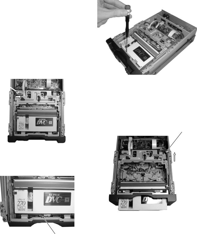
1.7HOW TO TAKE OUT THE CASSETTE TAPE IN CASE OF EMERGENCY
An emergency system on this unit enables the cassette tape to be taken out manually.
When a cassette tape is stuck, take it out as described below.
Procedure
1.Gear Å : Emergency gear for MODE MOTOR
2.Gear ı : Emergency gear for REEL MOTOR
3.Gear Ç : Emergency gear for HOUSING MOTOR
(1)In order to turn the mode motor, turn the gear Å(red color) in the direction of the arrow. While turning the gear also push it in to drive loading / unloading.
Gear Å
Fig. 1.7.1
(2)To wind the tape, when the tape is loosened a little, put a screw driver in the emergency gear ı, which drives the reel. (The drive direction does not matter.)
Gear ı
Fig. 1.7.2
Fig. 1.7.3
(3)Repeat steps (1) and (2) alternately and little by little until the tape is wound completely into the cassette.
(4)Confirm that the tape is completely wound. Then, turn the gear Ç (red color) in the direction of the arrow to eject the cassette housing. Take the cassette out when it comes out of the loading slot.
Gear Ç
Fig. 1.7.4
1-6
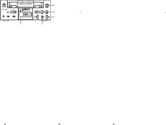
1.8SERVICE MENU
1.8.1 Usage procedure
(1)How to display the Service Menu
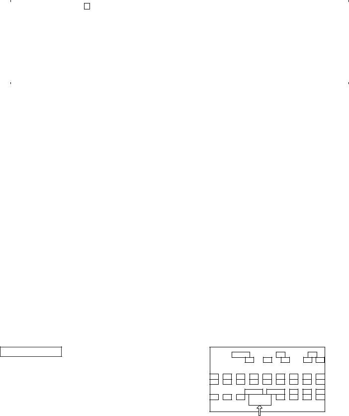
In no cassette condition, by pressing the MENU button for 2 seconds or longer while keeping either the STOP or PLAY button pressed, the first tier of the Service Menu will be displayed on the video monitor. As shown in Table 1.8.1, the Service Menu content that is displayed will differ depending on which buttons you press together simultaneously. (See Fig.8.1.1(2) to Fig.8.1.1(4)) (NOTE)
Only when displaying VTR 3 MENU, it is necessary to keep the PLAY + STOP buttons pressed while turning OPERATE ON. After that, press the MENU button for 2 seconds.
OPERATE |
|
|
|
|
|
|
EJECT |
|
|
|
|
|
|
|
|
|
|
|
|
|
|
|
MENU button |
|
|
|
|
|
|
|
MENIU |
Mini |
|
A.DUB |
|
|
REC |
PLAY |
PAUSE |
|
|
|
DVCAM NTSC PAL |
REC INH. |
|
|
PLAY [8] button |
PROFESSIONAL |
|
CH-1/3 |
|
|
|
||
MIC |
REMOTE SEL. |
INPUT SEL. |
|
REW |
STOP |
SET |
|
CH-2/4 |
|
FF |
|||||
|
SERIAL |
LINE |
|
|
|
FF [:] button |
|
|
9PIN WIRELESS |
DV Y/C |
BR-DV3000 |
|
|
|
|
|
|
|
|
|
|
||
|
|
|
REW [;] button |
|
STOP [9] button |
||
Fig. 1.8.1 (1) Front Panel
|
|
Activation Method |
||
Item |
Displayed Content |
STOP |
PLAY |
PLAY |
|
|
+STOP |
||
|
|
|
|
|
|
|
|
|
|
VTR1 MENU |
VCR 1 Menu |
|
|
|
VTR2 MENU |
VCR 2 Menu |
|
|
|
VTR3 MENU |
VCR 3 Menu |
|
|
(see note) |
DIP SW |
DIP SW Menu |
|
|
|
HOUR METER |
Hour Meter |
|
|
|
ERROR HISTORY |
Warning History |
|
|
|
OTHERS |
MENU SAVE etc. |
|
|
|
CPU VERSION |
CPU Version |
|
|
|
Table 1.8.1 Service Menu First Tier List
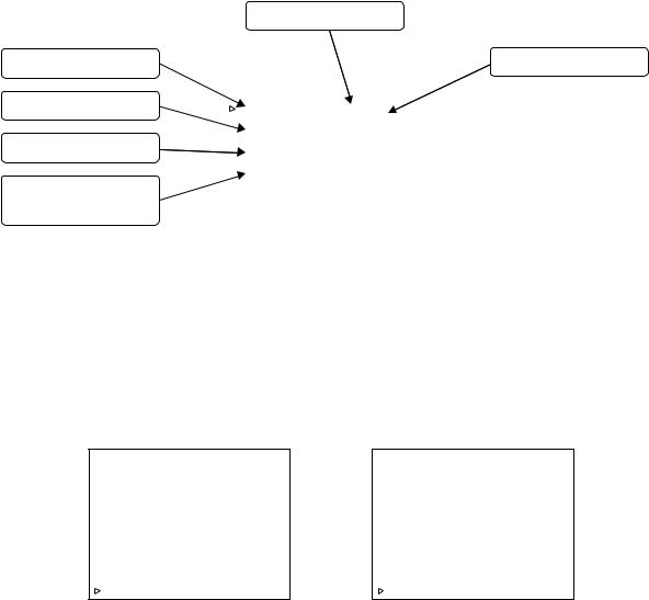
(2)How to operate the Menu
1 Press the 8 or 9 button on the front panel to move the cursor to the mode you want to change. 2 Press the [SET] (or : button) to select the item.
3 Press the 8 or 9 button to change the parameter.
4When finished making the change, press the [SET] button. The parameter stops blinking when the change has been confirmed. (Returning using the ; button or [MENU] button causes the setting to revert to the status prior to the change.)
5When all settings are completed, move the cursor to “PAGE BACK” and press the [SET] button to return to the MENU screen.
*If the ; button is pressed when the parameter is not blinking, it returns to the main screen.
*If the [MENU] button is pressed, it returns to the normal screen.
– – – M E N U – – – |
|
|
– – – M E N U – – – |
|
– – – M E N U – – – |
V T R 1 . . |
|
|
V T R 1 . . |
|
V T R 1 . . |
E X I T |
|
|
V T R 2 . . |
|
V T R 2 . . |
|
|
|
D I P S W . . |
|
V T R 3 . . |
|
|
|
H O U R M E T E R . . |
|
D I P S W . . |
C P U V E R S I O N |
|
|
E R R O R H I S T O R Y . . |
|
H O U R M E T E R . . |
S Y S |
0 0 0 1 |
|
O T H E R S . . |
|
E R R O R H I S T O R Y . . |
V T R |
0 1 0 2 |
|
E X I T |
|
O T H E R S . . |
|
|
|
|
|
E X I T |
|
|
|
|
|
|
Fig. 8.1.1(2) Menu Screen |
Fig. 8.1.1(3) Menu Screen |
Fig. 8.1.1(4) Menu Screen |
(with STOP pressed simultaneously) |
(with PLAY pressed simultaneously) |
(with PLAY + STOP pressed simultaneously) |
1-7
1.8.2 VTR 1 menu
Item |
|
|
|
|
|
Parameter |
|
|
|
|
|
|
|
REC REPEAT |
|
OFF |
|
|
|
No repeat recording |
|
2 |
|
|
|
Repeat recording 2 times |
|
|
12 |
|
|
|
Repeat recording 12 times |
|
|
|
ON |
Full repeat recording |
|||
FOOT SW LEVEL |
|
LEVEL1 |
Possible from any mode |
|||
|
|
|
|
|
|
Possible only from STOP or REC PAUSE mode |
|
|
LEVEL2 |
||||
|
|
|
|
|
|
|
MIC REC CH |
|
NORMAL |
Record input signal from connected MIC only on CH2 (CH4 : during A.DUB mode) |
|||
|
|
CH1-MIX |
[No recording mode]. Do not record input signal from connected MIC on CH1/CH2 |
|||
|
|
|
|
|
|
(No recording on CH3+4 during A.DUB) |
|
|
|
|
|
|
Record input signal from connected MIC on CH1/CH2 (CH3/CH4 during A.DUB) |
|
|
CH2-MIX |
||||
|
|
|
|
|
|
|
ID 422 (H) |
|
F0 |
High Device ID (00~FF). First bit is fixed at PAL1, NTSC0 |
|||
ID 422 (L) |
|
4E |
Low Device ID (00~FF) |
|||
FF/REW SPEED |
|
x50 |
Maximum FF/REW speed is regulated to x50 |
|||
|
|
x75 |
Maximum FF/REW speed is regulated to x75 |
|||
|
|
|
|
|
|
Maximum FF/REW speed is regulated to x100 |
|
|
x100 |
||||
|
|
MAX |
No maximum FF/REW speed regulation |
|||
DV DF MASK (PAL only) |
|
|
|
|
|
“1” is recorded as per format |
|
OFF |
|||||
|
|
ON |
“0” is always recorded |
|||
|
|
|
|
|
|
|
is default setting when shipped from factory.
Table 1.8.2 VTR 1 Menu Setting Item List
1.8.3 VTR 2 menu
Item |
|
|
|
Parameter |
|
|
|
|
|
LONG PAUSE |
|
OFF |
Disables long pause function |
|
|
|
|
|
Enables long pause function |
|
|
ON |
||
|
|
|
|
|
REC MODE |
|
|
|
SP recording |
|
SP |
|||
|
|
LP |
LP recording (Do not change since performance cannot be guaranteed) |
|
LP WARNING |
|
OFF |
LP INH not displayed (Enables playback with LP mode) (Do not change since |
|
|
|
|
|
performance cannot be guaranteed) |
|
|
|
|
LP INH displayed (Disables playback with LP mode) |
|
|
ON |
||
|
|
|
|
|
TEST SIGNAL |
|
|
|
Output color bars only. Do not output any other TEST signals. |
|
OFF |
|||
|
|
ON |
Use BARS button of a attached wireless controller reception to trigger output TEST |
|
|
|
|
|
signal, rotating in this order: |
|
|
|
|
Color bars e Color bars (rotate per track) e Grayscale e Grayscale (rotate per |
|
|
|
|
track) e Multi burst (Y signal only) e Multi burst (Y and C signals) e 100% white |
|
|
|
|
e Red e Black burst |
TEMP THRESHOLD |
|
|
|
Threshold of rising temperature warning display, 00~255 (220 [DCh] = internal |
220 |
|
|||
|
|
|
|
temperature approx. 60°C). Refer to item “TEMP” in table 1.8.7 (1) |
BATT. SHUT DOWN |
|
|
|
Voltage value to carry out power OFF operation (Set at OFF, 10.0~12.0 in |
10.5 |
||||
|
|
|
|
increments of 0.1) |
BATT. ALARM |
|
|
|
Voltage value to trigger display of battery alarm warning (Set at 10.0~12.0 in |
11.0 |
||||
|
|
|
|
increments of 0.1) |
|
|
|
|
|
|
|
|
|
is default setting when shipped from factory. |
|
|
|
|
Table 1.8.3 VTR 2 Menu Setting Item List |
1-8
1.8.4 VTR 3 menu
Changing of settings is prohibited.
Item |
|
Parameter |
|
|
|
RESERVED |
0 |
Standard setting |
|
|
|
is default setting when shipped from factory
Table 1.8.4 VTR 3 Menu Setting Item List
1.8.5 DIP switch menu
Sets the DIP SW. (All status are set to “OFF” or “0” when shipped.)
Item |
Parameter |
Default setting at factory |
||
|
|
|
|
|
DIP SW 1/3 |
|
|
|
|
DIP SW – 0 |
1: Displays error rate monitor and CPU port information |
|
0 |
|
|
|
|
|
|
DIP SW – 1 |
ON: Disables warning detection |
|
|
|
|
OFF |
|
||
|
|
|
|
|
DIP SW – 2 |
Change prohibited |
|
|
|
|
OFF |
|
||
|
|
|
|
|
DIP SW – 3 |
ON: Disables DEW warning |
|
|
|
|
OFF |
|
||
|
|
|
|
|
DIP SW – 4 |
Change prohibited |
|
|
|
|
OFF |
|
||
|
|
|
|
|
DIP SW – 5 |
Change prohibited |
|
|
|
|
OFF |
|
||
|
|
|
|
|
DIP SW – 6 |
Change prohibited |
|
|
|
|
0 |
|
||
|
|
|
|
|
DIP SW – 7 |
Change prohibited |
|
|
|
|
OFF |
|
||
|
|
|
|
|
DIP SW 2/3 |
|
|
|
|
DIP SW – 8 |
Change prohibited |
|
OFF |
|
|
|
|
|
|
DIP SW – 9 |
Change prohibited |
|
|
|
|
OFF |
|
||
|
|
|
|
|
DIP SW – 10 |
ON: Displays error rate solely for audio block on the error rate monitor screen |
|
|
|
|
OFF |
|
||
|
|
|
|
|
DIP SW – 11 |
Change prohibited |
|
|
|
|
OFF |
|
||
|
|
|
|
|
DIP SW – 12 |
Change prohibited |
|
|
|
|
OFF |
|
||
|
|
|
|
|
DIP SW – 13 |
Change prohibited |
|
|
|
|
OFF |
|
||
|
|
|
|
|
DIP SW – 14 |
Change prohibited |
|
|
|
|
OFF |
|
||
|
|
|
|
|
DIP SW – 15 |
Change prohibited |
|
|
|
|
OFF |
|
||
|
|
|
|
|
DIP SW 3/3 |
|
|
|
|
DIP SW – 16 |
Change prohibited |
|
OFF |
|
|
|
|
|
|
DIP SW – 17 |
Change prohibited |
|
|
|
|
OFF |
|
||
|
|
|
|
|
DIP SW – 18 |
Change prohibited |
|
|
|
|
OFF |
|
||
|
|
|
|
|
DIP SW – 19 |
Change prohibited |
|
|
|
|
OFF |
|
||
|
|
|
|
|
DIP SW – 20 |
Change prohibited |
|
|
|
|
OFF |
|
||
|
|
|
|
|
DIP SW – 21 |
Change prohibited |
|
|
|
|
OFF |
|
||
|
|
|
|
|
DIP SW – 22 |
Change prohibited |
|
|
|
|
OFF |
|
||
|
|
|
|
|
DIP SW – 23 |
Change prohibited |
|
|
|
|
OFF |
|
||
|
|
|
|
|
is default setting when shipped from factory
Table 1.8.5 DIP SW Menu Setting Item List
Error Rate Monitor
By setting DIP SW-0 to “1”, the error rate value is displayed in position [15] on the monitor screen.
The error rate value is always Viterbi ON mode, with CH-1 shown in the upper row, and CH-2 shown in the lower row and total AUDIO/VIDEO.
When the error rate increases, a warning message "HEAD CLEANING REQUIRED" is displayed. The detection threshold for display is when the error rate value is over 4,500 (one-chan- nel AV total) for 7 seconds consecutively.
|
D C |
1 |
|
T E M P |
1 |
D E W |
|
1 |
|
M O D E |
|
2 |
3 |
|
4 |
5 |
5 |
6 |
6 |
6 |
6 |
6 |
6 |
6 |
6 |
6 |
7 |
7 |
7 |
7 |
7 |
7 |
7 |
7 |
7 |
|
P O R T |
|
8 |
|
9 |
10 |
11 |
20 |
12 |
13 |
14 |
|
15 |
16 |
17 |
18 |
19 |
|
|
|
|
|
|
|
|
Error Rate Display Value
Fig.1.8.5 DIP SW-0 Display Screen
1-9

1.8.6 HOUR METER menu
Displays and resets the various types of hour meters.
When the parameter is set to “CLEAR” and the SET button is pressed, the hour meter is cleared.
Item |
|
|
|
Parameter |
Time duration/number of |
|
|
|
times display is possible |
||
|
|
|
|
|
|
|
|
|
|
|
|
DRUM |
|
Time display |
H |
Displays the drum hour meter (for drum maintenance) |
000000~999999 |
|
|
CLEAR |
|
Resets the drum hour meter |
Time duration |
TOTAL DRUM |
|
|
H |
Displays the total drum hour meter |
|
|
Time display |
000000~999999 |
|||
|
|
CLEAR |
|
Resets the total drum hour meter (Does not work unless the |
|
|
|
|
Time duration |
||
|
|
|
|
special setting) |
|
|
|
|
|
|
|
POWER |
|
|
H |
Displays the power hour meter |
000000~999999 |
|
Time display |
||||
|
|
CLEAR |
|
Resets the power hour meter |
Time duration |
CAPSTAN |
|
|
H |
Displays the capstan hour meter |
000000~999999 |
|
Time display |
||||
|
|
CLEAR |
|
Resets the capstan hour meter |
Time duration |
REEL FWD |
|
|
H |
Displays the reel forward direction running hour meter |
000000~999999 |
|
Time display |
||||
|
|
CLEAR |
|
Resets the reel forward direction running hour meter |
Time duration |
REEL REV |
|
|
H |
Displays the reel reverse direction running hour meter |
000000~999999 |
|
Time display |
||||
|
|
CLEAR |
|
Resets the reel reverse direction running hour meter |
Time duration |
LOADING |
|
|
|
Displays the number of times a tape was loaded |
000000~999999 |
|
Number display |
||||
|
|
CLEAR |
|
Resets the number of times a tape was loaded |
Number of times (events) |
EJECT (MINI) |
|
|
|
Displays the number of times a mini cassette was ejected |
000000~999999 |
|
Number display |
||||
|
|
CLEAR |
|
Resets the number of times a mini cassette was ejected |
Number of times (events) |
EJECT (STD) |
|
|
|
Displays the number of times a standard cassette was ejected |
000000~999999 |
|
Number display |
||||
|
|
CLEAR |
|
Resets the number of times a standard cassette was ejected |
Number of times (events) |
FWD/REV |
|
|
|
Displays the number of FWD/REV switchings |
000000~999999 |
|
Number display |
||||
|
|
CLEAR |
|
Resets the number of FWD/REV switchings |
Number of times (events) |
FF/REW |
|
|
|
Displays the number of FF/REW switchings |
000000~999999 |
|
Number display |
||||
|
|
CLEAR |
|
Resets the number of FF/REW switchings |
Number of times (events) |
CLEANER |
|
|
|
Displays the number of times the cleaner was activated |
000000~999999 |
|
Number display |
||||
|
|
CLEAR |
|
Resets the number of times the cleaner was activated |
Number of times (events) |
|
|
|
|
|
|
is default setting when shipped from factory
Table 1.8.6 HOUR METER Menu Setting Item List
1-10
1.8.7 ERROR HISTORY menu
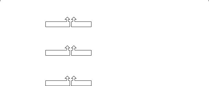
It can display 4 errors that have occurred in the past.
Initially, when there is no error history in the memory, the first error to occur will be logged in the first position (HISTORY-1). The second and third errors to occur will be logged in (HISTORY-2) and (HISTORY-3). All subsequent errors will be overwritten in (HISTORY-4).
The fourth and subsequent errors are set to overwrite in order to prevent the user from repeatedly attempting to use a malfunctioning unit and thereby erasing any record of the initial cause error. Be sure to clear the error history before returning a repaired unit to the customer. When resetting ERROR HISTORY, set the parameter for “CLEAR” to “EXECUTE”, and press the [SET] button.
Error Codes
First error display
Second error display
Third error display
Latest error display (Fourth and later are overwritten on here)
Error Name Display
– – – E R R O R H I S T O R Y – – – |
|
( H I S T O R Y – 1 ) |
7 1 0 1 |
C A P MO T O R F A I L U R E |
|
( H I S T O R Y – 2 ) |
7 1 0 1 |
C A P MO T O R F A I L U R E |
|
( H I S T O R Y – 3 ) |
7 1 0 1 |
C A P MO T O R F A I L U R E |
|
( H I S T O R Y – 4 ) |
7 1 0 1 |
C A P MO T O R F A I L U R E |
|
C R E A R |
C A N S E L |
P A G E B A C K |
|
|
|
Fig. 1.8.7 (1) ERROR HISTORY
(1)MECHANISM INFO (Detailed information when error occurs)
Move the cursor to the error code on the “ERROR HISTORY” screen, and press the [SET] button (or : button) to display the MECHANISM INFO screen as it was at the time of the error, you can check the details of the malfunction.
– – – M E C H A N I S M I N F O 1 / 2 – – –
P . T M 0 0 0 0 0 0 H
S Y S MO D E : P L A Y ( 0 1 , 0 0 ) M S D MO D E : P L A Y ( 0 1 , 0 0 )
|
|
– > S T O P ( 0 0 , 0 0 ) |
L A S T |
K E Y : P L A Y ( 0 0 , 0 0 ) |
|
T A P E R E M [ 0 0 0 0 ] |
||
D E W [ 0 0 ] |
T E M P [ 0 0 ] |
|
D I A M E T E R T U [ 0 0 ] S P [ 0 0 ] |
||
N E X T |
P A G E |
|
P A G E |
B A C K |
|
– – – M E C H A N I S M I N F O 2 / 2 – – –
M . P O S I B R K 2 F A S T > B R K 2 F A S T H . P O S I I N I T > C A S S I N C A P [ O F F F WD ] R E L [ O F F F WD ] D RM [ O F F ] D I R [ F WD ]
D R V [ 0 0 ] C A P V [ 0 0 ] R E L V [ 0 0 ] MC V / S P D [ 0 0 ] R E L I [ 0 0 ]
B G N [ O F F ] E N D [ O N ] C A S [ O F F ] S T D [ O F F ] HW [ O F F ] HW 2 [ O F F ] S P L [ O F F ] T H I N [ O N ]
P A G E B A C
Fig. 1.8.7 (2) MECHANISM INFO Display Screen
1-11
Item |
Content |
|
Displayed Content |
|
|||
|
|
|
|
|
|
|
|
P.TM |
POWER HOUR METER |
|
Power hour meter is display. |
|
|
||
|
|
|
|
||||
SYS MODE |
SYSCON CPU mode when error occurred |
SFF/SREW parameter is speed display. |
|
||||
|
PLAY (03, 00) |
(Refer to Fig. 1.8.7 (2) Speed parameter) |
|
||||
|
|
|
Parameters of other modes are irrelevant. |
||||
|
MODE DATA |
Parameter |
|
|
|
|
|
|
|
|
EJECT (01) |
: Eject |
|
ADUB (0B) |
: Audio Dub |
MSD MODE |
MSD CPU mode and target mode when |
STOP (02) |
: Stop |
|
ADBP (0C) |
: Audio Dub Pause |
|
|
error occurred |
|
PLAY (03) |
: Play |
|
REC (13) |
: Rec |
|
PLAY (01, 00) |
STL (04) |
: Still |
|
RECP (14) |
: Rec Pause |
|
|
|
|
FF (05) |
: FF |
|
DVRC (15) |
: DV Rec |
|
MODE DATA |
Parameter |
REW (06) |
: Rew |
|
DVRP (16) |
: DV Rec Pause |
|
|
|
SFF (07) |
: Search Fwd |
POFF (1A) |
: Power Off |
|
|
|
|
SREW (08) |
: Search Rev |
|
NDEF (1F) |
: During initial operation |
|
|
|
|||||
LAST KEY |
Final Key code when error occurred |
SFF/SREW parameter is speed display (See Fig. 1.8.7(2)) |
|||||
|
PLAY (E7, 01) |
Other parameters are 01: ON, 00: OFF |
|
||||
|
MODE DATA |
Parameter |
REC (E0) |
: Rec |
|
SFF (EB) |
: Search Fwd |
|
|
|
RECP (E1) |
: Rec Pause |
SREW (EC) : Search Rev |
||
|
|
|
DVRP (E2) |
: DV Rec Pause |
STOP (F0) |
: Stop |
|
|
|
|
ADUB (E5) |
: Audio Dub |
|
EJECT (F1) : Eject |
|
|
|
|
ADBP (E6) |
: Audio Dub Pause |
HWUP (F2) : Housing Up |
||
|
|
|
PLAY (E7) |
: Play |
|
HWDN (F3) : Housing Down |
|
|
|
|
STL (E8) |
: Still |
|
POFF (F4) |
: Power Off |
|
|
|
FF (E9) |
: FF |
|
DVRC (F5) |
: DV Rec |
|
|
|
REW (EA) |
: Rew |
|
PON (FA) |
: Power on |
|
|
|
|
||||
TAPE REM |
TAPE REMAIN |
|
Displays tape remaining in minutes ([FFFF] : not detected) |
||||
|
|
|
|||||
DEW |
DEW sensor A/D intake value |
DEW detects (at low temp. [13], at normal temp [CD]) |
|||||
|
|
|
DEW off (at low temp. [12], at normal temp [99]) |
||||
|
|
|
|||||
TEMP |
Temperature sensor A/D intake value |
Temperature is displayed in hexadecimal value. |
|||||
|
The value "49" [5 C] is threshold of |
-10°C a [22] |
20°C a [7C] |
50°C a [CC] |
|||
|
detecting low temperture. |
|
- 5°C a [2D] |
25°C a [8C] |
55°C a [D4] |
|
|
|
The value "DC" [60 C] is the threshold of |
0°C a [3A] |
30°C a [9C] |
60°C a [DC] |
|||
|
displaying "OVER HEATING" message. |
5°C a [49] |
35°C a [AA] |
|
|
||
|
|
|
10°C a [59] |
40°C a [B7] |
65°C a [E1] |
|
|
|
|
|
15°C a [6A] |
45°C a [C2] |
70°C a [E6] |
|
|
|
|
|
|||||
DIAMETER |
Displays wound tape diameter (Take-up, Supply) |
[00]—[FF] : 0mm-82mm (Diameter) ([00] is non-detected) |
|||||
|
|
|
|||||
M. POSI |
Mechanism position and target mechanism |
[2ULD], [ULD2BRK], [BRK], [BRK2FAST], [FAST], |
|||||
|
position |
|
[FAST2STP], [STP], [STP2SRH], [SRH], [SRH2], [INIT]("2" is |
||||
|
|
|
the meaning of "TO". It means transition. Refer to section 2, |
||||
|
|
|
Mechanism Timing Chart.) |
|
|
||
|
|
|
|||||
H. POSI |
Housing position and target housing position |
[EJECT], [EJECT2IN], [CASS IN], [RELEASE](Release the |
|||||
|
|
|
SUP reel lock.) |
|
|
|
|
|
|
|
[INIT](For the intake and eject operation, refer to section 8.2.3.) |
||||
|
|
|
|
|
|||
CAP |
Capstan status |
|
[ON] : Rotate |
[FWD/REV]: Direction display |
|||
|
|
|
[OFF] : Stop |
|
|
|
|
|
|
|
|
|
|||
REL |
Reel status |
|
[ON] : Rotate |
[FWD/REV]: Direction display |
|||
|
|
|
[OFF] : Stop |
|
|
|
|
|
|
|
|
|
|
|
|
DRM |
Drum status |
|
[ON] : Rotate |
|
|
|
|
|
|
|
[OFF] : Stop |
|
|
|
|
|
|
|
|
||||
DIR |
Direction of tape running (Direction of target) |
[FWD/REV] : Direction display |
|
||||
|
|
|
|
|
|
|
|
DRV |
Drum control voltage |
|
[00-FF] : 0—3V |
|
|
|
|
|
|
|
|
|
|
|
|
CAPV |
Capstan control voltage |
|
[00-FF] : 0—3V |
|
|
|
|
|
|
|
|
|
|
|
|
RELV |
Reel control torque value |
|
[00-FF] : 0—3A |
|
|
|
|
|
|
|
|
|
|
|
|
1-12
Item |
Content |
|
|
|
|
Displayed Content |
||
|
|
|
|
|
|
|
|
|
MCV/SPD |
Loading/cassette housing control voltage |
|
[00-FF] : 0—8V |
(Displays mode motor control voltage |
||||
|
(when error code 4xxx and error code 3xxx |
|
|
|
|
during error code 3xxx ) |
||
|
is displayed.) |
|
[00-FF] : 0-11V |
(Displays cassette motor control voltage |
||||
|
|
|
|
|
|
during error code 4xxx) |
||
|
Tape speed (When the code excepting |
|
[00-FA] : 0—25X |
(FF is displayed when the speed is faster |
||||
|
error code 4xxx and error code 3xxx is |
|
|
|
|
than this.) |
||
|
displayed.) |
|
|
|
|
“Tape speed” is a function to convert the |
||
|
|
|
|
|
|
hexadecimal value into a decimal value, |
||
|
|
|
|
|
|
and no speed parameter of the tape. |
||
|
|
|
|
|
|
(ex. FAh = 250 → The speed is 25.0X.) |
||
RELI |
Reel current (Cassette housing motor |
|
[00-FF] : 0—1.2A |
|
|
|
||
|
current during housing-related warning) |
|
|
|
|
|
|
|
|
|
|
|
|
|
|
|
|
BGN |
Begin sensor |
|
[ON] |
: Leader tape detected |
||||
|
|
|
[OFF] |
: Magnetic tape detected |
||||
|
|
|
|
|
|
|
|
|
END |
End sensor |
|
[ON] |
: Trailer tape detected |
||||
|
|
|
[OFF] |
: Magnetic tape detected |
||||
|
|
|
|
|
|
|
|
|
CAS |
Cassette SW status |
|
[OFF] |
: No cassette |
|
|
||
|
|
|
[ON] |
: Cassette detected (STD/MINI) |
||||
|
|
|
|
|
|
|
|
|
STD |
Standard cassette SW status |
|
[OFF] |
: Mini cassette tape inserted |
||||
|
|
|
[ON] |
: STD cassette tape inserted |
||||
|
|
|
|
|
|
|
|
|
HW, HW2 |
Housing SW/Housing 2SW status |
|
|
|
|
|
|
|
|
HW SW |
HW2 SW |
Housing status |
|
||||
|
|
|
|
|||||
|
|
|
[OFF] |
[ON] |
– |
|
||
|
|
|
|
|
|
|
||
|
|
|
[ON] |
[OFF] |
EJECT (Initial position) |
|
||
|
|
|
|
|
|
|
||
|
|
|
[OFF] |
[OFF] |
Cassette intake |
|
||
|
|
|
|
|
|
|
||
|
|
|
[ON] |
[ON] |
Ejecting Mini cassette |
|
||
|
|
|
|
|
|
|
|
|
|
|
|
|
|
|
|
|
|
SPL |
SUP Lock SW status (during loading) |
|
[ON] |
: Normal operation (TU side tape winding) |
||||
|
|
|
[OFF] |
: Lock release |
|
|
||
|
|
|
|
(Tape begin detected, Supply side tape winding mode) |
||||
|
|
|
|
|
|
|
|
|
THIN |
Thin tape detection |
|
[ON] |
: THIN |
|
|
|
|
|
|
|
[OFF] |
: NORMAL |
|
|
|
|
|
|
|
|
|
|
|
|
|
Table 1.8.7 (1) MECHANISM INFO content
Parameter |
Speed |
|
|
00 |
x 0 |
|
|
1F |
x 0.03 |
40 |
x 0.10 |
53 |
x 0.20 |
|
|
61 |
x 0.30 |
|
|
6D |
x 0.50 |
|
|
7A |
x 0.80 |
7B |
x 0.84 |
7D |
x 0.90 |
|
|
7F |
x 0.96 |
|
|
80 |
x 1.00 |
|
|
81 |
x 1.04 |
|
|
Parameter |
Speed |
|
|
82 |
x 1.08 |
|
|
83 |
x 1.11 |
84 |
x 1.12 |
85 |
x 1.16 |
|
|
91 |
x 2.00 |
|
|
A9 |
x 5.00 |
|
|
BD |
x 9.00 |
C0 |
x 10.0 |
C4 |
x 12.0 |
|
|
CC |
x 15.0 |
|
|
D3 |
x 20.0 |
|
|
|
|
Table 1.8.7 (2) Speed parameter
1-13

(2) Error code description
Error code |
Display |
Content of occurrence |
Method of detection |
Detected signal |
|
|
|
|
|
0201 |
CONDENSATION ON DRUM |
DEW detected |
If DEW sensor detects |
IC302 (MSD) –detects |
|
|
|
condensation |
voltage of pin 318 |
3200 |
LOADING FAILURE |
Does not load |
If mechanism position does |
IC302-pin354 |
|
|
|
not move in loading direction |
Rotary encoder output is |
|
|
|
within 5 seconds |
detected |
|
|
|
|
|
3300 |
UNLOADING FAILURE |
Does not unload |
If mechanism position does |
IC302-pin354 |
|
|
|
not move in unloading |
Rotary encoder output is |
|
|
|
direction within 5 seconds |
detected |
|
|
|
|
|
|
No display |
Does not intake |
If intake is not completed |
IC302 (MSD) –pin 84, |
|
|
|
within 5 seconds (Perform |
CASSETTE SW is not |
|
|
|
ejects without warning) |
detected within 5 seconds |
|
|
|
|
|
4100 |
CASSETTE EJECT FAILURE |
Does not eject |
If eject is not completed |
IC302 (MSD) –pin 26, |
|
|
|
within 5 seconds |
HOUSING SW is not |
|
|
|
|
detected within 5 seconds |
|
|
|
|
|
5605 |
DEFECTIVE TAPE |
Tape abnormality |
If begin and end sensor are |
IC302 (MSD) –pin 278, START |
|
|
during intake |
ON after intake |
sensor and pin 297, |
|
|
|
|
END sensor are both detected |
|
|
|
|
|
5606 |
DEFECTIVE TAPE |
Tape tear during |
If reel FG is excessive during |
IC302 (MSD) –pin 75, TU |
|
|
unloading |
unloading |
REEL FG is detected |
|
|
|
|
|
5607 |
DEFECTIVE TAPE |
Tape tear during |
If reel FG is insufficient during |
IC302 (MSD) –pin 75, TU |
|
|
loading |
loading |
REEL FG is detected |
|
|
|
|
|
5608 |
DEFECTIVE TAPE |
Tape tear on the |
If only supply side reel does |
IC302 (MSD) –pin 72, SUP |
|
|
loading side |
not rotate during FWD/REV |
REEL FG is not detected |
|
|
|
|
|
5609 |
DEFECTIVE TAPE |
Tape tear during |
If tape slack takeup is not |
IC302 (MSD) –pin 75, TU |
|
|
slack takeup |
completed within 10 seconds |
REEL FG and pin 72, SUP |
|
|
|
|
REEL FG are both detected |
5702 |
TAPE END DET. ERROR |
End sensor |
If trailer tape sending is not |
IC302 (MSD) –pin 297, END |
|
|
malfunction |
completed within 3 seconds |
sensor is detected for over 3 |
|
|
|
|
seconds |
|
|
|
|
|
5802 |
TAPE BEGIN DET. ERROR |
Begin sensor |
If leader tape sending is not |
IC302 (MSD) –pin 278, |
|
|
malfunction |
completed within 3 seconds |
START sensor is detected for |
|
|
|
|
over 3 seconds |
|
|
|
|
|
7001 |
DRUM MOTOR FAILURE |
Drum motor does |
If drum motor does not rotate |
IC302 (MSD) –pin 55, DRUM |
|
|
not rotate |
for over 4 seconds |
FG is not detected for over 4 |
|
|
|
|
seconds |
|
|
|
|
|
7101 |
CAP MOTOR FAILURE |
Capstan motor |
If capstan motor does not |
IC302 (MSD) –pin 56, CAP |
|
|
does not rotate |
rotate for over 2 seconds |
FG is not detected for over 2 |
|
|
|
|
seconds |
|
|
|
|
|
7202 |
SUPPLY REEL FAILURE |
SUP reel does not |
If SUP reel does not rotate for |
IC302 (MSD) –pin 72, SUP |
|
|
rotate |
over 3 seconds |
REEL FG is not detected for |
|
|
|
|
over 3 seconds |
|
|
|
|
|
7203 |
SUPPLY REEL FAILURE |
SUP side tape slack |
If only SUP reel does not |
IC302 (MSD) –pin 72, SUP |
|
|
|
rotate during REV |
REEL FG is not detected |
7302 |
TAKE UP REEL FAILURE |
TU reel does not |
If TU reel does not rotate for |
IC302 (MSD) –pin 75, TU |
|
|
rotate |
over 3 seconds |
REEL FG is not detected for |
|
|
|
|
over 3 seconds |
|
|
|
|
|
7303 |
TAKE UP REEL FAILURE |
TU side tape slack |
If only TU reel does not rotate |
IC302 (MSD) –pin 75, TU |
|
|
|
during FWD |
REEL FG is not detected |
|
|
|
|
|
7305 |
TAKE UP REEL FAILURE |
Tape slack during |
If TU reel FG is insufficient |
IC302 (MSD) –pin 75, TU |
|
|
unloading |
during unloading |
REEL sensor is detected |
|
|
|
|
|
7401 |
REEL MOTOR FAILURE |
Reel motor does |
If reel motor does not rotate |
IC302 (MSD) –pin 91, REEL |
|
|
not rotate |
for more than 4 seconds |
FG is not detected for over 4 |
|
|
|
during reel drive mode |
seconds |
|
|
|
|
|
Table 1.8.7 (3) Error Code Contents
1-14

1.8.8 OTHERS menu
Item |
|
|
|
|
|
|
|
|
Parameter |
||
|
|
|
|
|
|
|
|
|
|
|
|
MEMORY SW |
|
OFF |
|
|
Standard setting |
|
|
|
|
||
LOAD |
|
START |
Menu SW information is loaded from a store aria. |
||||||||
|
|
||||||||||
|
|
|
|
|
|
|
|
|
|
|
|
MEMORY SW |
|
|
|
|
|
|
|
|
|
|
|
|
OFF |
|
Standard setting |
|
|
|
|
||||
SAVE |
|
START |
Menu SW information is saved to a store aria. |
||||||||
|
|
||||||||||
|
|
|
|
|
Standard setting |
|
|
|
|
||
ALL RESET |
|
CANCEL |
|
|
|
|
|||||
|
|
I,U,E,EC |
Resets all EEP-ROM data to default settings except adjustment data, hour meter data, and |
||||||||
|
|
|
|
|
IEEE1394 ID data. |
|
|
|
|
||
|
|
|
|
|
Default settings differ by market region. |
||||||
|
|
|
|
|
I: for Japan, U: for USA, |
E: for EU, |
EC: for China |
||||
|
|
|
|
|
|
|
|
|
|
|
|
MEM.EDIT |
|
Contents of the EEP-ROM can be edited directly |
|||||||||
|
|
ADR: Address (0-03FF) display |
|
|
|
|
|||||
|
|
DATA: Display of data embedded in address shown by ADR |
|||||||||
|
|
|
|
|
|
|
|
|
|
|
|
|
|
Operation procedure |
|
|
|
|
|
||||
|
|
|
|
|
|
|
|
|
|
|
|
|
|
1 Press the 8 or 9 button to move the cursor to MEM or EDIT. |
|||||||||
|
|
2 Press the : button to make the ADR parameter blink. |
|||||||||
|
|
3 Press the 8 or 9 button to select the ADR parameter you want to edit. (Pressing 8 or 9 while keeping |
|||||||||
|
|
the “A.DUB” button pressed will cause it to count up or down in increments of 10.) |
|||||||||
|
|
4 Press the : button to make the DATA parameter blink. |
|||||||||
|
|
5 Press the 8 or 9 button to make changes in the DATA parameter. |
|||||||||
|
|
6 Press the [SET] button and confirm the DATA parameter. (The parameter stops blinking) |
|||||||||
|
|
(NOTE) |
|
|
|
|
|
|
|
||
|
|
The EEPROMs store important data for the system and careless rewriting may make normal operation of the |
|||||||||
|
|
system impossible. Do not use this function for purposes other than the IEEE1394 ID date that is described. |
|||||||||
|
|
|
|
|
|
|
|
|
|
|
|
|
|
|
|
|
|
|
|
|
|
|
|
OPERATION |
|
CANCEL |
Standard setting |
|
|
|
|
||||
CHECK |
|
EXECUTE Enters the OPERATION check mode. All LEDs turn on. By operating the relevant buttons and slide |
|||||||||
|
|
||||||||||
|
|
|
|
|
switches, the operation of the buttons and LEDs can be checked as shown in the following list. |
||||||
|
|
|
|
|
To exit from this mode, turn OPERATE to OFF. |
||||||
|
|
|
|
|
|
|
|
|
|
|
|
|
|
|
|
|
|
Button |
|
|
LED display contents |
|
|
|
|
|
|
|
|
OPERATE |
Power ON/OFF SW |
|
|||
|
|
|
|
|
|
EJECT |
Cassette tape LED goes out |
|
|||
|
|
|
|
|
|
STOP |
All except OPERATE LED go out |
|
|||
|
|
|
|
|
|
FF |
FF LED goes out |
|
|||
|
|
|
|
|
|
PLAY |
PLAY LED goes out |
|
|||
|
|
|
|
|
|
REW |
REW LED goes out |
|
|||
|
|
|
|
|
|
PAUSE |
PAUSE LED goes out |
|
|||
|
|
|
|
|
|
REC |
REC LED goes out |
|
|||
|
|
|
|
|
|
A.DUB |
A.DUB LED goes out |
|
|||
|
|
|
|
|
|
INPUT SELECT |
DV |
|
Rch LED comes on, Lch LED comes on |
|
|
|
|
|
|
|
|
|
|
LINE |
|
Rch LED comes on, Lch LED goes out |
|
|
|
|
|
|
|
|
|
Y/C |
|
Rch LED goes out, Lch LED comes on |
|
|
|
|
|
|
|
REMOTE/LOCAL |
9PIN |
|
DV CAM LED comes on, REC INH LED goes out |
|
|
|
|
|
|
|
|
|
|
SERIAL |
DV CAM LED goes out, REC INH LED comes on |
|
|
|
|
|
|
|
|
|
|
WIRELESS |
DV CAM LED comes on, REC INH LED comes on |
|
|
|
|
|
|
|
|
NTSC/PAL(REAR) |
NTSC |
|
NTSC LED comes on, PAL LED goes out |
|
|
|
|
|
|
|
|
|
|
PAL |
|
NTSC LED goes out, PAL LED comes on |
|
|
|
|
|
|
|
|
|
|
|
|
|
|
|
|
|
|
|
|
|
|
|
|
|
REAR SER. |
|
SERIAL |
|
REAR terminal is used as the SERIAL REMOTE terminal. |
|||||||
SEL |
|
TCCS |
REAR terminal is used as the TCCS terminal (factory use) |
||||||||
|
|
|
|
|
By pressing REC + ADB simultaneously while powering up, the forced TCCS mode is engaged. |
||||||
|
|
|
|
|
|
|
|
|
|
|
|
|
|
|
|
|
|
|
|
|
|
is default setting when shipped from factory |
|
|
|
|
|
|
|
Table 1.8.8 OTHERS Menu Setting Items List |
|||||
1-15

1.8.9 CPU version menu
Displays version of SYSCON CPU and MSD (VCR) CPU.
– – – M E N U – – –
V T R 1 . . E X I T
C P U |
V E R S I O N |
|
|
Firmware version |
|
S Y S |
0 0 0 1 |
|
CPU version |
SYSCON |
PLSL1144-VX-XX |
|
|||||
V T R |
0 1 0 2 |
|
|
MSD (VTR) |
PLSL1141-VX-XX |
|
|
|
|
||
Fig. 1.8.9 CPU Version Display
1.8.10 EEP-ROMS
(1)EEP-ROMS and stored data
BR-DV3000 is equipped with two EEP-ROMS for the purpose of data stored, and their contents are as per the following list. When the circuit board or EEP-ROM is replaced, there will be no data in the EEP-ROM. When the unit is powered up, and the SYSCON CPU or MSD CPU recognizes that there is no data in the EEP-ROM, it automatically writes initial data into the EEP-ROM to initialize it. The memory data shown in Table 1.8.10 will all be reset back to default settings, so it will be necessary to perform necessary adjustments and settings again.
EEP-ROM |
Circuit board name |
Memory data content |
|
|
|
IC301 |
DV/CPU circuit board |
• Adjusted data (DVC section: Adjustment menu No. 100-121) |
|
(MSD CPU) |
• IEEE1394 ID data |
|
MAIN circuit board |
• HOUR METER data |
|
|
|
IC2003 |
(SYSCON CPU) |
• Adjusted data (VCR section: Adjustment menu No. 200-274) |
|
|
• User menu and Service menu settings data |
|
|
• ERROR HISTORY |
|
|
|
Table 1.8.10 EEP-ROM Memory Data Content
(2)IEEE1394 ID setting method
IEEE1394 equipped units have an ID, as defined by the IEEE1394 standard, stored in the internal EEP-ROM (IC 301). At the time of production, the ID assigned for each individual unit are written into the EEP-ROM, and a sticker bearing the ID is affixed inside the unit. When the EEP-ROM (DV/CPU board assembly) or DV/CPU board assembly is replaced, the ID needs to be set again.
Procedure for setting IEEE1394 ID
The ID is an 8 digit, hexadecimal code, with 1 high Byte being the model code, and 3 low Bytes being individual to the unit. The model code is automatically initialized, so only the lower 3 Bytes of individual code need to be set manually. Go from Service Menu → OTHERS Menu → MEM. EDIT (Memory Edit) to select the address in the ID data section and make the setting directly. The 3 low Byte address is as follows. Make the setting while confirming the ID printed on the label (ID: 44xxxxxx) pasted on the inside of the BR-DV3000 (See Fig. 1.8.10).
IEEE1394 ID data |
: |
44 xx |
xx |
xx |
(Indicates on the label of BR-DV3000 inside.) |
|
|
h |
h |
h |
|
Address data |
|
“391” “392” “393” |
|||
1-16
Setting procedure
(1)Press the 8 or 9 button to move the cursor to MEM. EDIT.
(2)Press the : button to make the ADR parameter blink.
(3)Press the 8 or 9 button to select ADR parameter “391”.
(4)Press the : button to make the DATA parameter blink.
(5)Press the 8 or 9 button to set ADR = “391” for the ID.
(6)Press the [SET] button to confirm the DATA parameter.
(7)In the same manner, select ADR parameter “392” and “393” to set the ID data.
ID Display Label
Fig. 1.8.10 ID Label Attachment Position
1.8.11 Real-time clock
The IC2002 (RS5C314) on the MAIN circuit board is a CMOS real-time clock IC that sends time/calendar data to the CPU via serial transmission. When power is not being supplied to the BT2001, there is a secondary battery (3V) to backup the IC2002. By charging for 4 hours, it provides 3 months of backup. When power is being supplied, AL3V is sent through D2002 to the IC2002 8pin, and through D2003 the BT2001 enters a state of being charged. When external power supply (AL3V) ceases, BT2001 is discharged through D2002 and the current is sent to the IC2002 8pin, resulting in a state of backup.
IC2001
SYS CPU |
|
|
|
|
|
|
|
|
IRQO |
38 |
|
|
|
|
IC2002 |
||
39 |
1 |
|||||||
TCLKC |
CE |
VDD |
||||||
40 |
2 |
|||||||
IRQ1 |
SCLK |
OSCIN |
||||||
41 |
3 |
|||||||
TCLKD |
SIO |
OSCOUT |
||||||
|
||||||||
|
4 |
|||||||
|
|
VSS |
INTR |
|||||
|
|
|
|
|
|
|||
|
|
|
|
|
|
|
|
|
|
|
|
|
|
|
|
|
|
|
|
|
|
|
|
|
|
|
AL3V |
|
|
|
|
D2003 |
D2002 |
|
|
8 |
|
BT2001 |
|
|
|
7 |
|
|
6 |
|
|
5 |
|
|
|
X2003 |
GND |
|
32kHz |
|
|
|
Fig. 1.8.11 Real-time Clock Circuit
1-17
SECTION 2
MECHANICAL ADJUSTMENTS
2.1BEFORE ADJUSTMENTS
2.1.1 Precautions
1)Be sure to apply a screw securing torque when attaching a part.
The securing torque should be 0.14 N/m (1.4 kgf/cm) unless otherwise specified.
2)Always unplug the power cord of the set before attaching, removing or soldering a part.
3)When unplugging a connector, do not pull the wire but grasp the connector body.
4)Do not make an adjustment or rotate a potentiometer blindly while the source of trouble is not identified.
5)Before adjusting electrical circuitry, be sure to wait for more than 10 minutes after turning the power on.
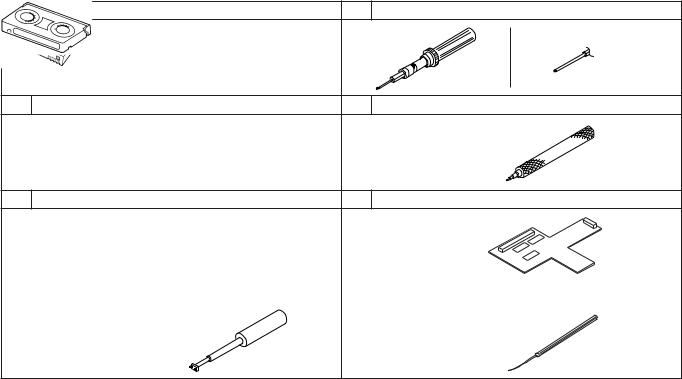
2.1.2 Measuring instruments required for adjustments
Instrument |
Condition |
Oscilloscope |
Calibrated instrument with measuring |
|
bandwidth of 100 MHz or more. |
|
|
|
Table 2-1-1 |
2.1.3 Equipment required for adjustments
1 |
Alignment tape |
5 |
Torque screwdriver |
|
MC-1 (NTSC) |
YTU94088 |
YTU94088-003 |
||
MC-2 (PAL) |
|
|
|
|
|
|
|
|
Replaceable bit |
|
|
|
|
(long type) |
2 |
DV tape |
6 |
Slit washer attaching tool |
|
For use |
YTU94121A |
|
||
in self-recording/playback. (60 ME) |
|
|
|
|
|
(270 ME) |
|
|
|
3 |
Cassette torque meter |
7 |
REWRITE board (Connector board) |
|
YTU94150A (or YTU94151A) for FWD mode |
CK453800B |
|
||
KLJ0312 for REV mode |
|
|
|
|
4 |
Guide screwdriver |
8 |
Chip IC replacement tool |
|
|
|
|
YTU94085 |
PTS40844-2 |
||
Table 2-1-2
2-1
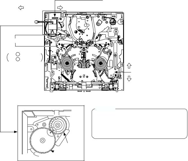
2.2DISASSEMBLY/ASSEMBLY OF THE MECHANISM
2.2.1 Mechanism position for disassembly/assembly
The mechanism should basically be disassembled and assembled in the unloading end (No Cassette) position.
However, other mechanism position is sometimes required for disassembly or assembly. In such a case, the required position is specified every time in the descriptions in 2.6, “Replacement of major parts”.
2.2.2 Mode transition
To change the mechanism mode manually, rotate the emergency gear of the mode motor assembly shown in Fig. 2.2.1 as below. The mechanism mode can be changed by applying 3 V DC to the mode motor electrodes.
The MINI and STD reel positions can be changed over by manually sliding the reel change plate.
|
|
Emergency gear (Mode motor) |
|
: Loading direction |
: Unloading direction |
|
Black wire |
|
DC 3 V |
|
|
|
Red wire |
|
Red – |
for loading |
|
Red + |
for unloading |
MINI |
|
|
|
|
|
Reel change plate |
|
|
STD |
|
|
Fig. 2.2.1 |
|
|
Important: |
|
|
When turn the Emergency gear (Mode) to Unloading di- |
|
|
rection by hand until the hole of the Main cam and the |
|
|
hole of the pinch cam in a straitline connecting. (refer to |
|
|
Fig.2.2.2) |
|
|
Please do not turn the Emergency gear (Mode) more than |
|
|
the above. |
Pinch cam
 Main cam
Fig. 2.2.2
2-2

2.3MECHANISM TIMING CHART
See Table 2-3-1 below. |
|
|
|
|
|
|
|
|
|
|
|
|
|
|
|
|
|
|
|
output SENSOR |
(T) BRAKE REEL |
|
(S) BRAKE REEL |
|
|
(T) SPRING .TEN |
|
|
(S) SPRING .TEN |
|
|
ARM TENSION |
|
|
ROLLER PINCH |
|
BASE POLE |
|
|
|
OFF |
ON |
OFF |
ON |
REW |
STOP |
REV |
FF |
FWD |
STOP |
OFF1 |
ON1 OFF2 |
ON2 |
OFF |
ON |
OFF |
ON |
EJECT, |
|
|
|
|
|
|
|
|
|
|
|
|
|
|
|
|
|
|
|
UNLOAD |
|
|
|
|
|
|
|
|
|
|
|
|
|
|
|
|
|
|
|
BRAKE |
|
|
|
|
|
|
|
|
|
|
|
|
|
|
|
|
|
|
|
FF/REW |
|
|
|
|
|
|
|
|
|
|
|
|
|
|
|
|
|
|
|
OFF-STBY |
|
|
|
|
|
|
|
|
|
|
|
|
|
|
|
|
|
|
|
SEARCH ON,-STBY |
REC, PLAY, |
|
|
|
|
|
|
Table 2-3-1 |
|
|
|
|
|
|
|
|
|
|
|||
2-3
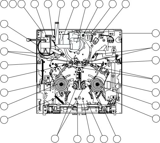
2.4 MAINTENANCE AND INSPECTION OF MAJOR PARTS
Periodical inspection and maintenance are requisite to maintain the initial performance and reliability of the product. Table 2-4-1 (Maintenance & Inspection List) has been compiled assuming standard operating conditions, and the specifications in the table are greatly variable depending on the actual operating environment and conditions. Remember that, if the maintenance and inspection are not enforced properly, the operating hours of
2.4.1 Layout of Major Parts
the product will not only reduce considerably but other unfavorable influences may produce.
Rubber parts may deform or degrade after long period of storage even if they are not used in this period.
The service life of the drum is variable depending on the tape used and operating environment.
5 |
6 |
7 |
4 |
34 |
36 |
1 |
2 |
3 |
26 |
27 |
35


 A 37
A 37 


D
D


 29 38
29 38 


28 |
|
|
|
C |
12 |
|
|
|
14 |
17 |
|
|
|
18 |
41 |
|
|
|
10 |
16 |
21 |
11 |
43 |
42 |
|
Fig. 2.4.1 |
|
|
|
2-4
2.4.2 Maintenance/inspection table
1)Replace the whole mechanism assembly in the 6000H maintenance.
2)The SUP/TU tension arm assemblies, sub-deck assembly (ENT. G. roller section) and EGR ARM assembly have undergone perpendicularity management after being assembled. If any of the above assemblies needs replacement, the whole mechanism assembly should be replaced.
|
Part Name |
Symbol |
|
|
Operating Hours (DRUM Hour Meter) |
|
|
Ref. |
|||||||
|
No. |
500 |
1000 |
1500 |
2000 |
2500 |
3000 |
3500 |
4000 |
4500 |
5000 |
5500 |
6000 |
Section |
|
|
|
||||||||||||||
|
|
|
|
|
|
|
|
|
|
|
|
|
|
|
|
1 |
° SUP P. BASE ASSEMBLY |
M 3 66 |
¤ |
R¤ |
¤ |
r |
¤ |
R¤ |
¤ |
r |
¤ |
R¤ |
¤ |
— |
2.6.17 |
|
|
|
|
|
|
|
|
|
|
|
|
|
|
|
|
2 |
· TU P. BASE ASSEMBLY |
M 3 67 |
¤ |
R¤ |
¤ |
r |
¤ |
R¤ |
¤ |
r |
¤ |
R¤ |
¤ |
— |
2.6.17 |
|
|
|
|
|
|
|
|
|
|
|
|
|
|
|
|
3 |
Î GUIDE ROLLER |
M 3 30 |
¤ |
R¤ |
¤ |
r |
¤ |
R¤ |
¤ |
r |
¤ |
R¤ |
¤ |
— |
2.4.1 |
|
|
|
|
|
|
|
|
|
|
|
|
|
|
|
|
4 |
Î COLLER |
M 3 31 |
¤ |
R¤ |
¤ |
r |
¤ |
R¤ |
¤ |
r |
¤ |
R¤ |
¤ |
— |
2.4.1 |
|
|
|
|
|
|
|
|
|
|
|
|
|
|
|
|
5 |
Î FRANGE |
M 3 32 |
¤ |
R¤ |
¤ |
r |
¤ |
R¤ |
¤ |
r |
¤ |
R¤ |
¤ |
— |
2.4.1 |
|
|
|
|
|
|
|
|
|
|
|
|
|
|
|
|
6 |
3 PINCH R.ARM ASSEMBLY |
M 3 4 |
¤ |
R¤ |
¤ |
r |
¤ |
R¤ |
¤ |
r |
¤ |
R¤ |
¤ |
— |
2.6.3 |
|
|
|
|
|
|
|
|
|
|
|
|
|
|
|
|
7 |
2 DRUM ASSEMBLY |
M 3 80 |
¤ |
¤ |
¤ |
r |
¤ |
¤ |
¤ |
r |
¤ |
¤ |
¤ |
— |
2.6.2 |
|
|
|
|
|
|
|
|
|
|
|
|
|
|
|
|
8 |
‡ CAPSTAN SHAFT |
M 3 64 |
¤ |
¤ |
¤ |
¤ |
¤ |
¤ |
¤ |
¤ |
¤ |
¤ |
¤ |
— |
|
|
|
|
|
|
|
|
|
|
|
|
|
|
|
|
|
9 |
‡ CAPSTAN MOTOR |
M 3 64 |
— |
— |
— |
— |
— |
— |
— |
— |
— |
R |
— |
— |
2.6.16 |
|
|
|
|
|
|
|
|
|
|
|
|
|
|
|
|
10 |
⁄ REEL MOTOR |
M 3 24 |
— |
— |
— |
— |
— |
— |
— |
— |
— |
R |
— |
— |
2.6.13 |
|
|
|
|
|
|
|
|
|
|
|
|
|
|
|
|
11 |
0 M.I.C. terminal |
M 3 51 |
¤ |
¤ |
¤ |
¤ |
¤ |
¤ |
¤ |
¤ |
¤ |
¤ |
¤ |
— |
|
|
|
|
|
|
|
|
|
|
|
|
|
|
|
|
|
12 |
0 M.I.C. CONNECTOR |
M 3 51 |
— |
— |
— |
— |
— |
— |
— |
— |
— |
— |
— |
— |
2.6.6 |
|
e FPC 1 ASSEMBLY |
M 3 49 |
¤ |
¤ |
¤ |
¤ |
¤ |
¤ |
¤ |
¤ |
¤ |
¤ |
¤ |
— |
2.6.25 |
|
! IDLER COVER |
M 3 52 |
— |
— |
— |
— |
— |
— |
— |
— |
— |
— |
— |
— |
2.6.7 |
13 |
Ç CASSETTE GUIDE PIN |
|
¤ |
¤ |
¤ |
¤ |
¤ |
¤ |
¤ |
¤ |
¤ |
¤ |
¤ |
— |
2.4.1 |
15 |
4 MODE MOTOR ASSEMBLY |
M 3 47 |
— |
— |
— |
— |
— |
— |
— |
— |
— |
— |
— |
— |
2.6.4 |
16 |
∞ MAIN CAM |
M 3 12 |
— |
— |
— |
— |
— |
— |
— |
— |
— |
— |
— |
— |
2.6.20 |
17 |
6 GEAR 1 |
M 3 44 |
— |
— |
— |
— |
— |
— |
— |
— |
— |
— |
— |
— |
2.6.4 |
18 |
7 GEAR 2 |
M 3 45 |
— |
— |
— |
— |
— |
— |
— |
— |
— |
— |
— |
— |
2.6.4 |
19 |
5 WORM WHEEL |
M 3 46 |
— |
— |
— |
— |
— |
— |
— |
— |
— |
— |
— |
— |
2.6.4 |
20 |
¢ PINCH CAM GEAR |
M 3 13 |
— |
— |
— |
— |
— |
— |
— |
— |
— |
— |
— |
— |
2.6.20 |
21 |
fl PINCH PLATE |
M 3 17 |
— |
— |
— |
— |
— |
— |
— |
— |
— |
— |
— |
— |
2.6.16 |
22 |
• CTL. PLATE |
M 3 9 |
— |
— |
— |
— |
— |
— |
— |
— |
— |
— |
— |
— |
2.6.22 |
23 |
¶ CTL. ARM ASSEMBLY |
M 3 56 |
— |
— |
— |
— |
— |
— |
— |
— |
— |
— |
— |
— |
2.6.21 |
24 |
§ ARM GEAR |
M 3 11 |
— |
— |
— |
— |
— |
— |
— |
— |
— |
— |
— |
— |
2.6.21 |
25 |
q SUP REEL PLATE ASSEMBLY |
M 3 54 |
— |
— |
— |
— |
— |
— |
— |
— |
— |
— |
— |
— |
2.6.24 |
26 |
w TU REEL PLATE ASSEMBLY |
M 3 55 |
— |
— |
— |
— |
— |
— |
— |
— |
— |
— |
— |
— |
2.6.24 |
27 |
& SUP REEL DISK ASSEMBLY |
M 3 35 |
— |
R |
— |
r^ |
— |
R |
— |
r^ |
— |
R |
— |
— |
2.6.10 |
28 |
* TU REEL DISK ASSEMBLY |
M 3 36 |
— |
R |
— |
r^ |
— |
R |
— |
r^ |
— |
R |
— |
— |
2.6.10 |
29 |
^ CONN. GEAR ASSEMBLY |
M 3 37 |
— |
R |
— |
r^ |
— |
R |
— |
r^ |
— |
R |
— |
— |
2.6.10 |
30 |
@ SUP TENSION BAND ASSEMBLY |
M 3 38 |
— |
R |
— |
r |
— |
R |
— |
r |
— |
R |
— |
— |
2.6.8 |
31 |
$ TU TENSION BAND ASSEMBLY |
M 3 39 |
— |
R |
— |
r |
— |
R |
— |
r |
— |
R |
— |
— |
2.6.9 |
32 |
! IDLER ARM ASSEMBLY |
M 3 40 |
— |
R |
— |
r |
R |
R |
— |
r |
— |
R |
— |
— |
2.6.7 |
33 |
1 HEAD CLEANAER |
M 3 5A |
R |
r |
R |
r |
— |
r |
R |
r |
R |
r |
R |
— |
2.6.2 |
34 |
ı CASSETTE HOUSING ASSEMBLY |
M 3 90 |
— |
— |
— |
— |
— |
— |
— |
— |
— |
— |
— |
— |
2.6.1 |
35 |
Å MECHANISM ASSEMBLY |
M 3 1 |
— |
— |
— |
— |
|
— |
— |
— |
— |
— |
— |
r |
|
¤: Clean with ethyl alcohol. R: Check and replace if required. r: Replace. ^: Oil the shaft. After replacing a part, apply lubricant to the required points.
Table 2-4-1
2-5
2.4.3 Cleaning
The tape transport system should be cleaned periodically. Be sure to clean the tape transport system upon receipt of a set for servicing, etc. To clean use a good quality fine-textured cloth moistened with ethyl alcohol.
1) When the video head is stained, the playback output level decreases and a read error will not be able to be corrected by the error correction. If this occurs, block noise appear on the monitor, the audio will not be output, and the video output will eventually be lost when the video head becomes extremely dirty. To clean the drum, while applying cleaning cloth (service part No. : KSMM-01) or high quality paper gently to the upper drum, rotate the upper drum in the normal (counterclockwise) rotation direction.
The dirt deposited on the video head can be removed by playing a cleaning tape.
CAUTION
Do not move the cleaning paper while applying it to the video head. Otherwise, the video head may be damaged.
2)The lower drum tends to attract dirt on the leader section and the linearity cannot be guaranteed when the lower drum becomes extremely dirty. Particularly, the tape inlet and output sections gather dirt easily, causing symptoms such as dropout of the reproduced FM signal, deterioration of video quality and lack of audio output. In order to clean the leader section, rub a a cotton swab gently along its edge.
High-quality paper
|
. |
Apply |
lightly |
|
Core drum
Upper drum
Head tip
Carefully clean the lead tape inlet/outlet.
Toothpick
Lead
Lower drum
Fig. 2.4.2
3)Stain of the tape transport system leads to tape damage. When magnetic dust or dirt penetrates inside the rollers, a rotation malfunction may affect the video. Clean the tape transport parts carefully using a cleaning cloth or cotton swab moistened with ethyl alcohol.
 Take special care.
Fig. 2.4.3
2.4.4 Oiling and Greasing
Table 2-4-2 shows the oil and greases used with the set.
Classification |
Name |
Part No. |
Oil |
Cosmo Hydro HV100 |
YTU94027 |
Grease |
Maltemp SH-P |
KYODO-SH-P |
|
Hanal |
RX-410R |
Table 2-4-2
1)Oiling should be performed periodically. Oil the shafts by referring to the maintenance table.
2)After replacing a part, grease the required points. For the parts to be greased see the exploded diagram in chapter 5, “DISASSEMBLY DRAWINGS AND PARTS LIST”.
3)As Hanal separates over time, be sure to mix it (shake) well before use.
4)Take care not to leave grease or oil on the tape transport parts which come into contact with the tape or on the brake pads.
5)Take care not to apply too much oil or grease. The standard oiling quantity is one drop and the standard greasing quantity is the quantity with which the grease does not overflow.
2-6

2.5PERIODICAL MAINTENANCE
Perform maintenance at the correct times in accordance with the maintenance table.
Fig. 2-5-1 shows the flow chart of periodical maintenance procedures at different operating hours.
Every 2000-hour maintenance
Start
Replaced parts
° SUP. Pole Base assembly · TU Pole Base assembly
ÎGuide roller
ÎColler
ÎFrange
3 Pinch roller arm assembly
2 Drum assembly
& SUP R. disk assembly * TU R. disk assembly ^ CONN. gear assembly
@ SUP tension band assembly $ TU tension band assembly ! Idle arm assembly
1Head cleaner
2.6.8SUP. TEN. BAND adjustment
2.6.9TU. TEN. BAND adjustment
2.8Toeque adjustment
2.9Interchangeability adjustment
3.2.1PB switching point adjustment
6000-hour maintenance
Start
Replaced parts
Mechanism assembly (including Drum assembly and Cassette housing assembly)
2.8Toeque adjustment
2.9Interchangeability adjustment
3.2.1PB switching point adjustment
3.2.3ME SP VCO OFFSET adjustment
End
3.2.3 ME SP VCO OFFSET adjustment
End
Fig. 2.5.1
2-7
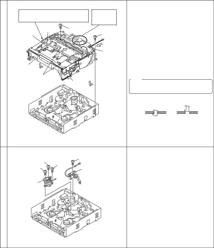
No. |
Item |
Ref. Illustration |
Procedure |
|
|
|
|
2.6REPLACEMENT OF MAJOR PARTS
The disassembly procedures shown in oder of disassembly. To remove the part, it is necessary to have completed all the stages before it.
Always use a torque driver and the specified securing torque to tighten screws.
Position the mechanism to the unloading end (No Cassette) mode before disassembly or assembly unless otherwise specified.
1 ı Cassette housing assembly |
|
|
<Disassembly> |
||
Cassette housing assembly Manually perform |
Hold this part |
1)Turn the cassette housing motor emergency gear |
|||
in the direction of the arrow, while pushing the lock |
|||||
the loading operation so that the cassette holder |
when removing |
||||
bar comes on the position of this screw. |
or attaching |
lever in the direction of arrow 2, then move the |
|||
|
|
|
the assembly. |
cassette holder so that the cassette holder bar |
|
|
Cassette |
|
|
||
|
|
|
comes in the position shown in the illustration. |
||
Cassette |
holder bar |
(S1) |
(S1) |
||
2)Remove two screws (S1), slide the cassette hous- |
|||||
|
|
||||
holder |
|
|
|
||
|
|
|
ing toward the front and remove it by releasing the |
||
|
|
|
|
||
|
|
|
1 |
lock on the Hook function as shown by arrow 3. |
|
|
|
2 |
Cassette |
<Assembly> |
|
|
|
|
|||
|
|
|
Housing |
1)Reverse the disassembly procedure. |
|
|
|
|
Motor |
||
Hook |
|
|
Emergency |
2)Screws (S1) should be tightened using a securing |
|
|
|
Gear |
torque of 0.2 N/m (2 kgf/cm). |
||
|
3 |
|
|||
|
|
|
|||
|
Look lever |
|
|
Note: |
|
|
|
Hook |
3 |
||
|
|
Be sure to attach the cassette housing in the |
|||
|
|
|
|
||
|
|
|
|
same position as when it was removed. |
|
|
|
(OK) |
(NG) |
|
|
Hook function of the Cassette hausing. |
|
|
Fig. 2.6.1 |
|
|
2 1 Head cleaner assembly/ 2 Drum assembly |
<Disassembly> |
|
|
|
(S2) |
Head cleaner assembly: |
|
(S3) 2 |
1)Remove the screw (S2) and remove the head |
||
(S3)3 |
(S3) 1 |
cleaner assembly. |
|
Head cleaner assembly |
|
||
|
|
|
|
|
|
Drum assembly: |
|
|
|
1)Remove the Drum FPC from the DV/CPU circuit |
|
Drum assembly |
|
board CN107. |
|
|
|
2)Remove the screw (S3) and remove the drum as- |
|
|
|
sembly. |
|
|
|
<Assembly> |
|
|
|
1)Reverse the disassembly procedure. |
|
|
|
2)Drum section screws (S3) should be tightened in |
|
|
|
order of 1 — 3 and using a securing torque of |
|
|
|
0.04 N/m (0.4 kgf/cm). |
|
Fig. 2.6.2
2-8
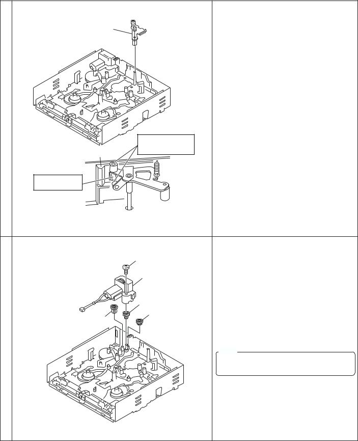
No. |
Item |
Ref. Illustration |
Procedure |
|
|
|
|
3 3 Pinch roller arm assembly |
<Disassembly> |
|
1)While pushing the hook on the pinch plate, lift the |
Pinch roller |
pinch roller arm assembly upward to remove. |
|
|
arm assembly |
<Assembly> |
|
|
|
1)Reverse the disassembly procedure. |
|
Please pay attention |
|
not to damage these |
Pinch plate |
roller part. |
|
Remove while pushing this part.
Fig. 2.6.3 |
|
|
4 4 Mode motor assembly/ 5 Worm wheel 2/ 6 Gear 1/ 7 Gear 2 |
<Disassembly> |
|
(S2) |
Mode motor assembly: |
|
1)Remove the screw (S2) and remove the mode |
||
|
||
|
motor assembly. |
|
Mode motor |
Worm wheel 2 & gears 1 and 2: |
|
assembly |
||
|
1)Lift the worm wheel 2 upward to remove. |
|
Worm wheel 2 |
2)Lift the gear 1 upward to remove. |
|
Gear 1 |
3)Lift the gear 2 upward to remove. |
|
|
||
Gear 2 |
<Assembly> |
|
|
||
|
1)Reverse the disassembly procedure. |
|
|
Note: |
|
|
Worm wheel 2 and gears 1 and 2 do not re- |
|
|
quire the mechanism phase adjustment. |
Fig. 2.6.4
2-9
 Loading...