


 Loading...
DV VIDEO CASSETTE RECORDER
DV VIDEOKASSETTENREKORDER ENREGISTREUR A CASSETTE DIGITAL VIDEO DV VIDEOREGISTRATORE
UNIDAD GRABADORA DE VÍDEO DV
BR-DV3000E |
INSTRUCTION MANUAL |
||
BEDIENUNGSANLEITUNG |
|||
|
|
|
MODE D’EMPLOI |
|
|
|
|
|
|
|
ISTRUZIONI PER L’USO |
|
|
|
|
MANUAL DE INSTRUCCIONES
English
Deutsch
Français
Español
OPERATE
EJECT
|
|
|
|
|
|
MENIU |
|
Mini |
A.DUB |
|
REC |
PLAY |
PAUSE |
|
|
|
DVCAM NTSC PAL |
REC INH. |
|
|
PROFESSIONAL |
|
CH-1/3 |
|
|
|
|
MIC |
REMOTE SEL. |
INPUT SEL. |
REW |
STOP |
SET |
|
CH-2/4 |
FF |
|||||
|
SERIAL |
LINE |
|
|
|
|
|
9PIN WIRELESS |
DV Y/C |
BR-DV3000 |
|
|
|
|
|
|
|
|
|
|
Italiano
Thank you for purchasing this JVC product. Before operating this unit, please read the instructions carefully to unsure the best possible performance.
LLT0025-001D-H

Supplement
This equipment is in conformity with the provisions and protection requirements of the corresponding European Directives. This equipment is designed for professional video appliances and can be used in the following environments:
5Residential (including both of the location type class 1 and 2 found in IEC 1000-2-5)
5Commercial and light industrial (including, for example, theatres)
5Urban outdoors (based on the definition of location type class 6 in IEC 1000-2-5)
This apparatus is designed for rack mounting or is used close to other apparatus.
In order to keep the best performance and furthermore for electromagnetic compatibility we recommend to use cables not exceeding the following lengths:
Port |
Cable |
Length |
AUDIO |
SHIELDED CABLE |
10 meters |
LINE |
COAXIAL CABLE |
10 meters |
Y/C |
COAXIAL CABLE |
10 meters |
DV |
SHIELDED TWIST PAIR CABLE |
4 meters |
REMOTE |
TWIST PAIR CABLE |
5 meters |
The inrush current of this apparatus is 1.7 amperes.
Caution:
5Where there are strong electromagnetic waves or magnetism, for example near a radio or TV transmitter, transformer, motor, etc., the picture and sound may be disturbed. In such a case, please keep the apparatus away from the sources of the disturbance.
E-2
SAFETY PRECAUTIONS
Warning Notice
FOR YOUR SAFETY (Australia)
1.Insert this plug only into effectively earthed three-pin power outlet.
2.If any doubt exists regarding the earthing, consult a qualified electrician.
3.Extension cord, if used, must be three-core correctly wired.
IMPORTANT (In the United Kingdom) Mains Supply (AC 230 V `)
WARNING – THIS APPARATUS MUST BE EARTHED
The wires in this mains lead are coloured in accordance with the following code;
GREEN-and-YELLOW : EARTH
BLUE |
: NEUTRAL |
BROWN |
: LIVE |
As the colours of the wires in the mains lead of this apparatus may not correspond with the coloured markings identifying the terminals in your plug, proceed as follows.
The wire which is coloured GREEN-AND-
YELLOW must be connected to the terminal in the plug which is marked with the letter E or by the safety earth symbol  or coloured GREEN or GREEN-AND-YELLOW. The wire which is coloured BLUE must be connected to the terminal which is marked with the letter N or which is coloured BLACK. The wire which is coloured BROWN must be connected to the terminal which is marked with the letter L or coloured RED.
POWER SYSTEM
Connection to the mains supply
This unit operates on voltage of 220 V to
240 V AC, 50 Hz/60 Hz.
WARNING:
TO REDUCE THE RISK OF FIRE OR ELECTRIC SHOCK, DO NOT EXPOSE THIS APPLIANCE TO RAIN OR MOISTURE.
CAUTION
To prevent electric shock, do not open the cabinet. No user serviceable parts inside. Refer servicing to qualified service personnel.
Note:
The rating plate and the safety caution are on the rear of the unit.
The OPERATE button does not completely shut off mains power from the unit, but switches operating current on and off.
WARNING
It should be noted that it may be unlawful to rerecord pre-recorded tapes, records, or discs without the consent of the owner of copyright in the sound or video recording, broadcast, or cable programme and in any literary, dramatic, musical or artistic work embodied therein.
Caution for AC Mains Lead
FOR YOUR SAFETY PLEASE READ THE FOLLOWING TEXT CAREFULLY.
This product is equipped with 2 types of AC cable. One is for continental Europe, etc. and the other one is only for U.K.
Appropriate mains cable must be used in each local area, since the other type of mains cable is not suitable.
FOR CONTINENTAL EUROPE, ETC. |
FOR U.K. ONLY |
Not to be used in the U.K. |
If the plug supplied is not suitable for your |
|
socket outlet, it should be cut off and |
|
appropriate one fitted. |
|
|
E-3
Thank you for purchasing our DV Video Cassette Recorder BR-DV3000.
As this is a DV-format video cassette recorder, video cassettes with the or
or 


 logos can be used with it.
DVCAM cassettes can be recorded in DV format.
ThisVTR features dual support for NTSC and PAL. Certain functions however, are supported by only one signal system.They are indicated with (NTSC only) or (PAL only).
●In order to prevent crumpling due to tape slack, please do not perform important recording within the first and last 2 – 3 minutes run of the tape.
●Recorded video (music) is meant for personal entertainment only and must not be used for other purposes without the prior consent of the copyright owner.
●Our company shall not guarantee the content of any recording effort should this VTR fail to record normally due to defects, either of the main unit itself or the video cassette tape.
E-4
MAIN FEATURES
●DV format
High picture and sound quality by digital technology.
●Compatible mechanisms for standard/mini DV cassettes
It records on and plays back DV cassettes of the standard and mini size. (SP mode only)
DVCAM cassettes can be recorded in DV format.
A tape recorded with the DVCAM format can be used only for playback for this VTR.
●Equipped with composite and Y/C input & output terminal devices.
●Equipped with DV IN/OUT terminals. (IEEE1394)
It can exchange digital signals with IEEE1394compatible devices.
●Dual support for NTSC/PAL
Switch between NTSC or PAL as required. This makes it easy to work with internationally sourced material and transfer it to a non-linear system for editing.You can also record to Standard DV or Mini DV tape in either NTSC or PAL system.
●Wireless/wired remote control
It can be controlled with the provided wireless remote controller or the optional wired remote controller RM-G30.
●Support for RS-422A interface
It can be used as a player for an editing system that uses the RS-422A-compatible editing remote controller RM-G820.
●Recording/playback of time codes
●Audio-dubbing (after-recording) function
Audio dubbing at a sampling frequency of 32kHz is allowed on CH3 and CH4 (except during DV input).
●Backup recording function
By linking with other DV devices, long-duration continuous recording is possible.
●Indexed search and blank search function
It can search for indexed signal recorded positions or unrecorded parts.
●Repeat play function
There are 3 types of repeat function. (INDEX/ VIDEO END/ TAPE END)
●Can be placed in an upright position
With the use of the provided stand, it can be positioned upright.

TABLE OF CONTENTS
INTRODUCTION |
|
Precautions .................................................... |
6 |
Daily maintenance and regular inspection ..... |
7 |
Precautions on the use of cleaning tape ........ |
8 |
Cassette tape ................................................. |
8 |
Condensation ................................................. |
9 |
NAMES AND FUNCTIONS OF VARIOUS PARTS |
|
Front panel ................................................... |
10 |
Rear panel .................................................... |
14 |
Wireless remote controller ........................... |
16 |
ON-SCREEN DISPLAY |
|
Regarding on-screen display ........................ |
18 |
Status display ............................................... |
19 |
Event display ................................................ |
21 |
Alarm display ................................................ |
22 |
PREPARATION |
|
Provided wireless remote controller ............. |
24 |
Power ........................................................... |
26 |
Selecting the NTSC/PAL signal system ....... |
28 |
OPERATION LOCK mode ............................ |
29 |
Loading/ejecting cassettes ........................... |
30 |
Setting/displaying date and time .................. |
31 |
RECORDING |
|
Connection and setting ................................ |
34 |
Setting time codes ........................................ |
36 |
Recording method ........................................ |
38 |
Audio dubbing .............................................. |
39 |
Backup recording function ............................ |
40 |
Recording using the serial remote terminal ... |
41 |
PLAYBACK |
|
Connection/setting ....................................... |
42 |
Basic playback method ................................ |
44 |
Special playback function ............................. |
45 |
Locate function ............................................. |
47 |
Repeat playback ........................................... |
48 |
Selecting playback audio output ................... |
49 |
EDIT |
|
Using the unit in an editing system .............. |
50 |
MENU SCREEN |
|
Structure of the menu ................................... |
53 |
Setting the menu .......................................... |
54 |
Contents of the menus ................................. |
56 |
OTHERS |
|
Placing the unit in an upright position .......... |
65 |
Warning display ............................................ |
66 |
Troubleshooting ............................................ |
68 |
Checking the hour meter .............................. |
69 |
Specification ................................................. |
70 |
E-5

INTRODUCTION
Precautions
Place of storage and use
Please avoid storing or using this VTR in the following places:
●Extremely hot or cold places beyond the allowable temperature for operation (5˚C – 40˚C).
●Humid or dry places beyond the allowable humidity range for operation (30% –80% RH).
●Dusty or sandy places.
●Places exposed to oil, smoke or steam, such as the kitchen vicinity.
●Intensely vibrating or unstable places.
●Places prone to condensation.
●Places that generate strong magnetic fields, e.g., transformer or motor.
●Places near devices that generate electric waves, e.g., transceiver or mobile phone.
●Places that generate radiation, X-rays or corrosive gases.
Handling the unit
●Please do not place heavy objects on the VTR, like a monitor or TV.
●Please do not insert foreign objects into the cassette slot.
●Mind your finger when loading the cassette.
Please be careful not to get your fingers clamped when loading the cassette to prevent injury.
●Place this VTR out of reach of young children. As injury may result from fingers getting clamped when loading the cassette, please keep this VTR out of reach of young children.
●Please do not block the ventilation openings.
●Avoid violent shocks to the unit. Do not drop the unit.
●Please remove the cassette tape from the cassette slot when transporting the unit.
●Please remove the AC adapter to save energy when the unit is not in use.
Maintaining the unit (Please turn off the power before performing maintenance work.)
Please wipe the unit with a soft cloth. Do not wipe it with thinner or benzene lest the surface melts or becomes dull. For stubborn stains, wipe first with a water-diluted neutral detergent and then wipe dry.
Please use the provided AC adapter to connect the VTR to a power source.
Use the supplied power cord. Using a different type or damaged cord may cause fire or electric shock.
E-6

Daily maintenance and regular inspection
This unit uses consumables or components that will wear off. If a worn-out or deteriorated component continues to be used, it may cause the unit to break down. To prevent this, please perform daily maintenance using the head-cleaning tape. With the head-cleaning tape alone, however, the entire tape-winding mechanism cannot be completely cleaned.
Please perform regular maintenance of the components as shown below.
Regular inspection (maintenance)
The tasks of maintenance involved are similar to that of replacing the engine oil or tire of a car. Depending on the number of usage hours, please clean, inspect or replace the components as follows:
Number of hours |
500H |
1000H |
1500H |
2000H |
4000H |
|
|
|
|
|
|
Drum assembly (including head) |
|
|
|
|
|
|
|
|
|
|
|
Head cleaner |
|
|
|
|
|
|
|
|
|
|
|
Tape guide, roller |
|
|
|
|
|
|
|
|
|
|
|
Reel disk • tension bands |
— |
|
— |
|
|
|
|
|
|
|
|
— : Inspection
: Cleaning, inspection and adjustment
: Cleaning and inspection; Replacement if necessary
: Replacement
Maintenance necessity and frequency depends on the environment and usage. The above information serves only as a guide.
Usage Time |
: You can check the drum usage time via the hour meter display. |
|
For details, please refer to page 69, “Checking the hour meter”. |
Maintenance consultation |
: For details on the maintenance plan and fee, please consult with |
|
your nearest JVC-authorized service agent. |
Head cleaning
●Recording or playing back with a stained head will result in block noise or disrupted sound. Please perform regular head cleaning to maintain superior image and sound quality.
●If dust adheres on the head, “HEAD CLEANING REQUIRED!” will be displayed on the monitor when this unit plays a tape.
HEAD CLEANING REQUIRED!
Block noise
●For information on how to use the head cleaning tape and the relevant precautions, please refer to page 8, “Precautions on the use of cleaning tape”.
E-7
INTRODUCTION
Precautions on the use of cleaning tape
Please use cleaning tape produced by JVC.
Please follow the instructions below when using the cleaning tape.
1. The tape will run for 10 seconds in the PLAY mode. (Thereafter, it stops automatically and enters the STOP mode.)
•After loading the cleaning tape, press the PLAY button.
2.For a single cleaning session, use it up to 4 times.
3.Please refer to the following table as a guide for cleaning.
Memo:
1.Under low humidity conditions, (10% RH to 30%
RH), please perform head cleaning at intervals of half of the following stated periods.
2.If M-DV80 is used immediately after cleaning, the VTR warning (“HEAD CLEANING
REQUIRED!”) may disappear only after the tape has run for some time.
3.Please use the cleaning tape at room temperature (10˚C to 35˚C).
4.Instructions for using the cleaning tape are stated inside its case. The contents may be slightly different from those stated here.
Please follow the instructions in this manual.
Operating environment |
Low temperature |
Room temperature |
High temperature |
of the unit |
5˚C to 10˚C |
10˚C to 35˚C |
35˚C to 40˚C |
|
|
|
|
Guide for using |
1 to 2 times every |
1 to 2 times every |
1 to 2 times every |
cleaning tape |
5 hours |
20 to 30 hours |
5 hours |
|
|
|
|
Cassette tape
This unit can record onto and playback standard DV and mini DV cassette tapes (for SP mode only). Please use the following JVC cassettes with the
or the 


 logos.
● Standard DV cassettes |
● Mini DV cassettes |
LA-DV276 |
M-DV63PR0 |
LA-DV186 |
M-DV60 |
LA-DV124 |
M-DV30 |
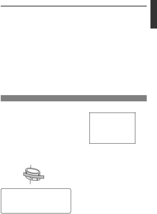
Erasure prevention
DV cassettes have a safety slide at the back to prevent accidental erasure.
●To prevent accidental erasure of important records, push the slide to the “SAVE” position.
●To record, push the slide to the “REC” position.
Slide
Memo
●DVCAM cassettes can be recorded in DV format. Tapes recorded in DVCAM format can be played (SP Mode).
●M-DV80 cassettes(Mini DV 80min tape) cannot be used with this unit.
Precautions on the use of tape
REC
SAVE
●Reverse sides of videotapes cannot be used.
●Please store the tape only after it has been fully rewound, so as to avoid damaging the tape.
●Please store the cassette in places low in humidity, well-ventilated and fungus-proof.
●When a cassette is used repeatedly, noise may increase due to e.g., dropout, etc. hence affecting its performance. Please do not use dirty or damaged tapes as they will shorten the life span of the rotation head.
E-8
For recording and storing videotapes in the best condition
Observe the following instructions for the best recording and storage of videotapes.
●Take care of the conditions of handling videotapes.
It is recommended that you record and store videotapes in the environment below.
|
|
|
Storage |
|
|
Recording |
Short period |
|
Long period |
|
|
(Up to 10 years) |
|
(Over 10 years) |
|
|
|
|
|
Temperature |
17°C to 25°C |
15°C to 23°C |
|
15°C to 19°C |
|
|
|
|
|
Humidity |
30% to 70% |
40% to 55% |
|
25% to 35% |
|
|
|
|
|
Hourly temperature change |
Less than 10°C |
– |
|
– |
|
|
|
|
|
Hourly humidity change |
Less than 10% |
– |
|
– |
●Do not leave the videotapes neglected for a long period.
If videotapes are left wound for a long period of time, it may result in distortion of the tape. Also it may cause tape-to-tape adhesion (known as blocking). It is recommended that videotapes be unspooled and rewound once a year for refreshing.
●When tapes are not in use, store them in cases and on end.
Storage cases protect videotapes from humidity, dust and ultraviolet. Keep tapes in cases and do not store them lying flat. When housed in a horizontal position, pressure from other tapes can cause distortions and deformations of the tape edges.
Condensation
●When this unit is moved from a cold to a warm place abruptly, the vapor in the warm air will come into contact with the head drum or the tape guides. When chilled, the vapor turns into droplets of water. This state is known as condensation. When condensation occurs, the videotape will adhere to the head drum or the tape guides and will be damaged.
●Condensation occurs on this unit in the following circumstances:
•It is moved abruptly from a cold place to a warm place.
•It is used in a room immediately after the heater has been turned on, or when cold breeze from an air-conditioner blows onto it.
•It is used at a place of high humidity.
 Head drum
 Videotape
When a cassette tape is loaded, please do not transport e.g., from an external cold place to a warm room thereby subjecting the unit to drastic temperature changes.
After moving the unit, please do not use it until the innards are stabilized.
●When condensation occurs, the monitor displays the following warning:
CONDENSATION ON DRUM
To remedy, leave the unit with the power ON and wait until the WARNING indicator disappears.
●Prevention of condensation
When transporting the BR-DV3000 from a cold to a warmer place abruptly, first take out the cassette.Then place the BR-DV3000 in a plastic bag and seal it before transporting the camera.
Leave the BR-DV3000 in the sealed plastic bag until the camera has the same temperature as the surroundings.This will prevent condensation.
E-9
NAMES AND FUNCTIONS |
– Front panel – |
OF VARIOUS PARTS |
|
|
|
2 |
|
|
|
|
OPERATE |
|
|
|
|
|
|
EJECT |
|
|
|
|
|
|
|
|
1 |
|
|
|
|
|
|
|
|
|
|
|
|
|
|
MENIU |
Mini |
|
A.DUB |
|
|
REC |
PLAY |
PAUSE |
|
|
|
DVCAM NTSC |
PAL |
REC INH. |
|
|
PROFESSIONAL |
|
CH-1/3 |
|
|
|
|
|
|
|
|
|
|
|
SET |
|
MIC |
REMOTE SEL. |
INPUT SEL. |
CH-2/4 |
|
REW |
STOP |
FF |
|
SERIAL |
LINE |
|
|
|
|
|
|
9PIN WIRELESS |
DV Y/C |
BR-DV3000 |
|
|
|
|
|
|
|
|
|
|
||
|
|
4 3 |
|
|
|
|
|
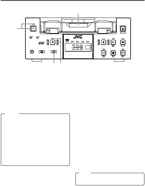
1 [OPERATE] Operate button/LED |
3 [A. DUB] Audio dubbing button/LED |
||||||
●Press this button to turn on the power and operate the unit. (Operate ON)
Press this button again to turn off the power.
(Operate OFF)
●The OPERATE LED lights up as follows.
Operate ON |
: the LED lights up green |
Operate OFF |
: the LED lights up red |
VTR error |
: the LED blinks in red |
Memo
●When the DC IN MODE item of the SYSTEM menu is set to “OPE ON” and power is supplied to the 1DC IN terminal located at the rear panel, the unit goes into the OPERATE ON state even if this button is not pressed.
●Even when the power has been turned off with this button, a small amount of electricity will still be channeled into the unit.
Therefore, if the unit is not going to be used for a long period of time, please remove the AC adapter to reduce energy consumption.
2Cassette slot
● Load a cassette into or unload it from the slot.
Please insert a standard DV or a mini DV cassette. ( Page 30)
● When the unit is in the OPERATE OFF state and if a cassette is loaded, it goes into the ON state.
●Press this button for audio dubbing (after-re- cording).
For audio dubbing, set the AUDIO MODE item of the AUDIO/VIDEO menu to “32K”.
Sound produced by the 6 MIC terminal or the 9 AUDIO IN terminal at the rear panel
( Page 15) is recorded on CH3 and CH4 channels.
●During audio dubbing, the A. DUB LED lights up red.
●If the INPUT SEL. switch is set at “DV”, audio dubbing is not possible.
( Page 39, “Audio dubbing”)
4[INPUT SEL.] Input video signal selection switch
● Select the video signal input with this switch. Y/C : YC separate video signals from the Y/
C IN terminal
LINE : composite video signals from the LINE IN terminal
DV : DV signals from the DV IN/OUT termi-
nal (IEEE1394)
Note
During recording, manipulating this switch will not bring about any effect.
E-10
OPERATE |
|
|
|
|
|
|
|
|
EJECT |
|
|
|
|
|
|
|
|
|
|
|
|
|
|
|
|
|
|
|
7 |
|
|
|
|
|
|
|
|
|
MENIU |
Mini |
|
A.DUB |
|
|
|
REC |
PLAY |
PAUSE |
|
|
|
|
|
DVCAM |
NTSC |
PAL |
REC INH. |
|
|
PROFESSIONAL |
|
|
CH-1/3 |
|
|
|
|
|
|
|
|
|
|
|
|
|
|
SET |
|
MIC |
REMOTE SEL. |
INPUT SEL. |
CH-2/4 |
|
|
REW |
STOP |
FF |
|
|
SERIAL |
|
LINE |
|
|
|
|
|
|
|
9PIN WIRELESS |
DV |
Y/C |
BR-DV3000 |
|
|
|
||
|
|
|
|
|
|
|
|||
6 |
5 |
|
|
|
|
|
|
|
|
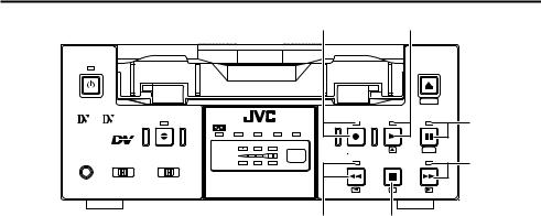
5[REMOTE SEL.] Remote select switch
Use this switch to select the remote controller type.
9 PIN |
: Select this to use the RS-422A- |
|
compatible editing remote con- |
|
troller (RM-G820) that connects |
|
to the 49 PIN REMOTE termi- |
|
nal located at the rear panel. |
|
Please use this unit as a player. |
|
* This setting is valid only when |
|
the REMOTE item of the RE- |
|
MOTE menu is set to ON. |
SERIAL |
: Select this to use the serial re- |
|
mote controller (RM-G30) that |
|
connects to the 3SERIAL RE- |
|
MOTE terminal located at the |
|
rear panel. |
|
* This setting is valid only when |
|
the REMOTE item of the RE- |
|
MOTE menu is set to ON. |
WIRELESS : Select this to use the provided wireless remote controller.
6[MIC] Microphone input terminal
This is the mini jack for monaural microphone input. When this terminal is connected to a microphone, sound input via the AUDIO IN terminal located on the rear panel is not recorded.
Sound from this terminal is recorded on CH1/ CH2 in the RECORD mode and CH3/CH4 in the AUDIO DUBBING mode.
7[EJECT] Eject button
●Press this button to eject the cassette.
Memo
It takes about 6 seconds for the cassette to be ejected.
●If no cassette is loaded and this button is pressed for at least 2 seconds, a menu will be displayed on the monitor connected to the VIDEO LINE OUT or Y/C OUT terminal.
●When the menu is displayed, pressing this button will resume the usual screen.
( Page 54, “Setting the menu”)
Memo
●When 9 PIN or SERIAL is selected, the buttons on the unit you wish to render operable
can be selected from the LOCAL FUNCTION item of the REMOTE menu. ( Page 59)
●During OPERATION LOCK, this switch will not be effective.
●Control via the DV IN/OUT terminal is possible (ie unaffected by the switch setting).
E-11
NAMES AND FUNCTIONS |
– Front panel – (continued) |
OF VARIOUS PARTS |
|
|
|
|
|
|
|
8 |
|
|
9 |
|
OPERATE |
|
|
|
|
|
|
|
|
|
EJECT |
|
|
|
|
|
|
|
|
|
|
|
|
|
|
|
|
|
|
|
|
|
|
|
MENIU |
|
Mini |
|
A.DUB |
|
|
|
|
REC |
PLAY |
PAUSE |
0 |
|
|
|
DVCAM |
NTSC |
PAL |
REC INH. |
||||||
|
|
|
|
|
|
|
|
||||
PROFESSIONAL |
|
|
CH-1/3 |
|
|
|
|
|
|
|
|
|
|
|
|
|
|
|
|
|
SET |
|
|
MIC |
REMOTE SEL. |
INPUT SEL. |
CH-2/4 |
|
|
|
REW |
STOP |
FF |
! |
|
|
SERIAL |
|
LINE |
|
|
|
|
|
|
||
|
9PIN WIRELESS |
DV |
Y/C |
BR-DV3000 |
|
|
|
|
|
||
|
|
|
|
|
|
|
|
|
|||
|
|
|
|
|
|
|
# |
|
@ |
|
|
8[REC] Record button/LED
●Hold down this button and press the 9 PLAY button to start recording. During recording, the
LED lights up red.
●Hold down this button and press the 0PAUSE button to pause the recording.
●When this button is pressed during recording, an index signal is recorded on the tape (valid when the INDEX WRITE item in the SYSTEM menu is set to ON).
●When recording is stopped, the time code generator value can be verified by holding this button down. If the TC DUPLICATE menu item is set to AUTO or NON DROP, EE signals of the DV Input time code and Date/Time can be verified.
●When the unit is in the STOP mode, press this button to execute fast-forward winding of the tape.
●When the unit is in the PLAYBACK or STILL mode, press this button to execute fast-for- ward playback. The Fast-forward playback speed changes in the following sequence each time this button is pressed:
X20¥X5¥X10¥X20...
In the DVCAM mode, the maximum speed is 15X.
●During fast-forward winding or fast-forward playback, the LED lights up green.
●When the menu is displayed, use this button to display selected menu items.
When setting up the date, time or time code, use this button to select the data segment.
9[PLAY] Play button/LED
●Press this button to start playing back a tape. During playback, the LED lights up green.
●When recording is paused, press this button to resume recording.
●When the menu is displayed, use this button to select the menu items or setting values.
0[PAUSE] Pause button/LED
●During recording, press this button to pause it.
During playback or STOP mode, press this button to enter the STILL mode.When recording is paused or when the unit is in the STILL mode, the LED lights up green.
●If this button is pressed simultaneously with the A.DUB button in the STILL mode, the Audio Dubbing Pause mode will be engaged.
●When the menu is displayed, use this button to confirm the menu items or setting values.
! [FF] Fast forward button/LED
@[STOP] Stop button/LED
●Press this button to stop operation. (of rewind, playback, etc.)
●When the menu is displayed, use this button to select the menu items or setting values.
#[REW] Rewind button/LED
●When the unit is in the STOP mode, press this button to rewind the tape.
●When the unit is in the PLAYBACK or STILL mode, press this button to execute reverse playback. The Reverse playback speed changes in the following sequence each time this button is pressed:
X20¥X5¥X10¥X20...
In the DVCAM mode, the maximum speed is 15X.
●During rewinding or reverse playback, the LED lights up green.
●When the menu is displayed, press this button to return to the previous screen.
When setting up the date, time or time code, use this button to select the data segment.
E-12
|
|
% |
|
|
$ ^ |
|
|
OPERATE |
|
|
|
|
|
|
EJECT |
|
|
|
|
|
|
|
|
|
|
|
|
|
|
|
MENIU |
Mini |
|
A.DUB |
|
|
REC |
PLAY |
PAUSE |
|
|
|
DVCAM NTSC |
PAL |
REC INH. |
|
|
PROFESSIONAL |
|
CH-1/3 |
|
|
|
|
|
|
|
|
|
|
|
SET |
|
MIC |
REMOTE SEL. |
INPUT SEL. |
|
|
REW |
STOP |
|
CH-2/4 |
|
FF |
|||||
|
SERIAL |
LINE |
|
|
|
|
|
|
9PIN WIRELESS |
DV Y/C |
BR-DV3000 |
|
|
|
|
|
|
|
|
|
|
||
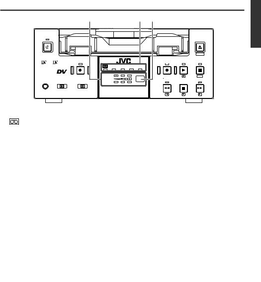
$ Indicator |
|
|
|
% Audio indicator |
|
||
: When a cassette is loaded, the LED lights up green. (Likewise when the unit is in the OPERATE OFF state.)
When a cassette is being loaded or ejected, the LED blinks.
DVCAM : When the unit plays back a tape recorded in the DVCAM format, the LED lights up green.
NTSC : The LED lights up green in the following cases:
•In the composite video orYC video signal input mode and the 2 NTSC/PAL switch located at the rear panel ( Page 14) is set as
“NTSC”.
•A tape recorded with NTSC signals is played back.
•When NTSC system DV signals are input while the INPUT SEL. switch is set at “DV”.
PAL : The LED lights up green in the following cases:
•In the composite video orYC video signal input mode and the 2 NTSC/PAL switch located at the rear panel is set as “PAL”.
•A tape recorded with PAL signals is played back.
•When PAL system DV signals are input while the INPUT SEL. switch is set at “DV”.
REC INH : The LED lights up red for about 5 seconds when the unit is set to the recording mode but fails to record. E.g. when the rear slide of the cassette is pushed to the “SAVE” position.
This indicator allows the user to check the availability of audio signals.
3 indicators each are available to CH1/3 and Ch2/4.
^ Sensor for wireless remote controller
When using the provided wireless remote controller, please point it to this sensor.
( Page 25, “Using the wireless remote controller”)
E-13
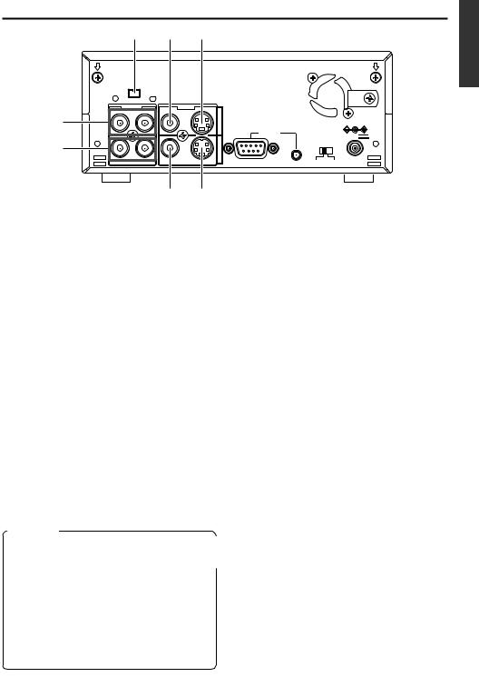
NAMES AND FUNCTIONS |
– Rear panel – |
OF VARIOUS PARTS |
DV IN/OUT |
|
|
|
|
AUDIO |
CH 2/4 |
LINE |
VIDEO |
Y/C |
CH 1/3 |
|
IN |
|
|
|
|
REMOTE |
|
DC12V |
|
|
|
|
OUT |
|
NTSC/PAL |
1 |
|
|
||
9PIN |
|
SERIAL NTSC PAL |
|
4 3 2
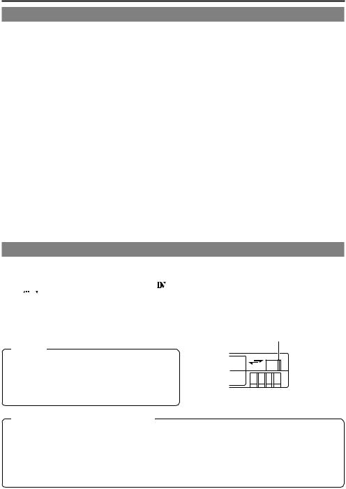
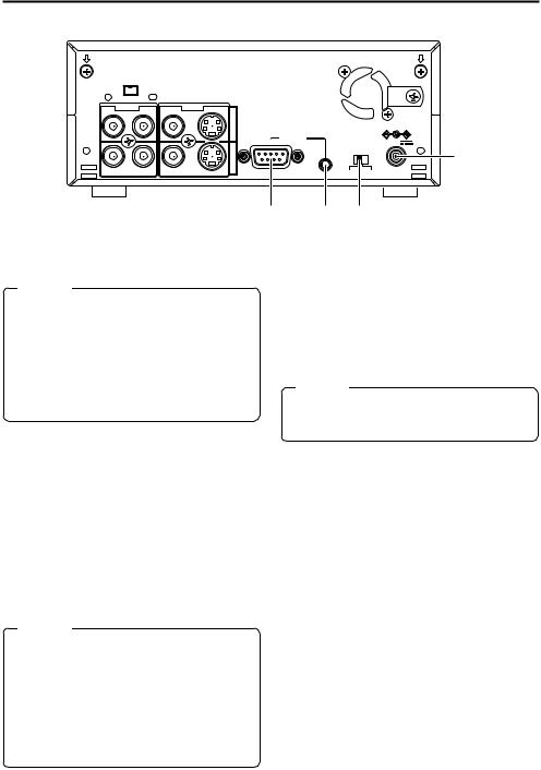
1 DC power input terminal (2P)
This is used for DC12V input. It connects the DC power cord of the provided AC adapter.
Memo
●When power is supplied to this terminal, the OPERATE indicator located at the front panel lights up. (The LED lights up red when the OPERATE indicator is OFF.)
●Setting this unit to OPERATE ON, OPERATE OFF or PLAY mode when the power is supplied to this terminal can be done by making the appropriate selections from the DC IN MODE item in the SYSTEM menu.
2[NTSC/PAL] NTSC/PAL signal selection switch
Use this switch to select NTSC or PAL as the signal system. Use it to make a selection when composite video signals or YC separate video signals are input.
NTSC : Use this setting for NTSC signal input.
The NTSC indicator on the front panel lights up.
PAL : Use this setting for PAL signal input.
The PAL indicator on the front panel lights up.
3[SERIAL REMOTE] serial remote terminal (mini jack)
Connect this terminal to the serial remote controller RM-G30, which is available separately. To control this unit via this terminal, please set it up as follows.
●Set the REMOTE item of the REMOTE menu to “ON”.
●Set the REMOTE SEL. switch on the front panel to “SERIAL”.
Memo
To use this terminal as the FOOT switch input terminal, please set the FOOT SW item of the REMOTE (2/2) menu. ( Page 60)
4[9 PIN REMOTE] 9-pin remote terminal (D-SUB)
Use this terminal to connect to the RS-422A- compatible editing remote controller (RM-G820). Please use this unit as a player. To control this unit with this terminal, please set it up as follows:
●Set the REMOTE item of the REMOTE menu to “ON”.
●Set the REMOTE SEL. switch on the front panel to “9 PIN”.
Memo
●For playback or DV signal input, signals are determined automatically and not affected by the status of this switch.
●Please turn the unit to OPERATE OFF before using this switch. If switching is performed when the VTR is in the OPERATE
ON mode, the VTR will automatically go into the OFF mode before engaging the ON mode.
●It cannot be used for NTSC/PAL conversion.
E-14
9
0
! 6 5
DV IN/OUT |
|
|
|
|
AUDIO |
CH 2/4 |
LINE |
VIDEO |
Y/C |
CH 1/3 |
|
IN
REMOTE
DC12V
OUT |
NTSC/PAL |
|
|
9PIN |
SERIAL NTSC PAL |
87
E-15
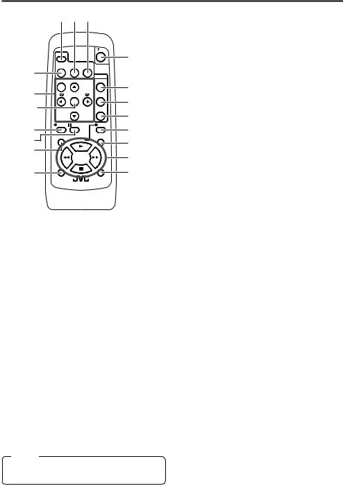
NAMES AND FUNCTIONS
OF VARIOUS PARTS – Wireless remote controller –
2 4 5 |
|
4 [STILL MODE] button |
||
|
|
|
|
Use this button to select images in the STILL |
|
|
|
|
mode. |
|
|
|
|
When the unit is in the STILL mode, press this |
DISPLAY |
|
|
1 |
button to toggle images in the following se- |
|
|
|
quence. |
|
BARS |
STILL |
BLANK |
|
|
MODE |
|
Field image (1st/2nd alternate still) ¥ 1st field |
||
3 |
|
AUDIO |
|
|
|
|
|
image ¥ 2nd field image ¥ frame image |
|
MENU |
SEARCH+ |
MUTING |
|
|
9 |
|
|
OUT SEL. |
|
|
SET |
|
SET |
|
SEARCH– |
OUT LEV. |
button |
|
|
|
0 |
A.DUB |
PAUSE |
REC |
|
|
|
|
! |
F.REV |
PLAY |
F.ADV |
|
|
||
$ |
|
|
|
|
REW |
|
FF |
|
|
STOP |
|
^ |
INDEX– |
|
INDEX+ |
|
|
REMOTE CONTROL UNIT
RM-G3000
6
75 [BLANK] button
8 |
When the unit enters the STOP mode, press |
|
this button to begin a blank search. Once it finds |
||
@ |
a blank part of the tape, it will enter the STILL |
|
mode. ( Page 47) |
||
# |
||
|
&6[AUDIO MUTING] button
During playback, press this button to mute the % audio output. Press this button again to re-en-
able audio output.
7[AUDIO OUT SEL.] button
1 [OPERATE] button f
Press this button to turn on the power of the unit. (OPERATE ON)
Press this button again to turn off the power. (OPERATE OFF)
2 [DISPLAY] button
Use this button to turn on/off, the on-screen (e.g. status screen) display on the monitor connected to the VIDEO LINE OUT terminal and Y/C OUT terminal. Each time this button is pressed, the display mode changes in the following sequence: ON (always display) ¥AUTO (display when switching mode) ¥ OFF.
( Page 18, “On-screen display”)
3[BARS] button
When this button is pressed in the Stop or RECPause mode, the color bar of the built in signal generator will be output. When it is pressed again, the screen returns to the usual display. During DV signal input, the color bar will not be output.
Note
Please do not use it as the standard signal because the signals are simplified.
When playing back tapes recorded in the 32K mode, use this button to select the audio channel that allows output from the AUDIO OUT terminal.
CH1/2 ¥ CH3/4 ¥ MIX
8[AUDIO OUT LEV.] button
Use this button to switch the standard level of the playback or EE audio output (NORMAL or ATT). When it is set to ATT, the output level is reduced by 8dB.
9Buttons related to menu setting and variable speed playback
[MENU] button
When the unit enters the STOP mode and this button is pressed, a menu will be displayed on the monitor connected to the VIDEO LINE OUT or Y/C OUT terminal. When the menu is displayed, press this button to return to the usual screen display.
[SEARCH+] / button
•During playback, STILL mode or variable speed playback in the forward direction, press this button to speed up playback.
•During reverse playback or variable speed playback in the reverse direction, press this
button to slow down the playback speed. ( page 46)
•When the menu is displayed, use this button to select the menu items or setting values.
E-16

[SEARCH–] / button
•During playback, STILL mode or variable speed playback in the forward direction, press this button to slow down the playback speed.
•During reverse playback or variable speed playback in the reverse direction, press this
button to speed up the playback speed. ( page 46)
•When the menu is displayed, use this button to select the menu items or setting values.
[P] / button
•During reverse payback/ variable-speed playback, press this button to execute forward playback.
•When the menu is displayed, use this button to display the selected menu items. During date/time or time code setup, press this button to move the cursor to the right.
[p] / button
•During forward playback/ variable-speed playback, press this button to execute reverse playback.
•When the menu is displayed, press this button to display the previous menu. During date/time or time code setup, press this button to move the cursor to the left.
SET button
During menu display, press this button to confirm the menu items or setting values.
0[A. DUB] button
Press this button to perform audio dubbing (af- ter-recording). ( Page 39, “Audio dubbing”)
![PAUSE] button
During recording, audio dubbing or playback, press this button to pause recording or enter the STILL mode.
If this button is pressed in the STOP mode, the STILL mode will be engaged.
@[REC] button
●Hold down this button and press the PLAY button to begin recording.
●During recording, press this button to record an index on the tape. (when the INDEX WRITE item of the SYSTEM menu is set to ON)
●When the unit enters the STOP mode, holding this button down will enable you to check the value of the time code generator.
#[F. ADV] button
Each time this button is pressed in the STILL mode, the image is advanced one frame. When holding down this button, the image is advanced continuously frame by frame.
$[F. REV] button
Each time this button is pressed in the STILL mode, the image is reversed one frame. When holding down this button, the image is reversed continuously frame by frame.
Memo
The image of frame advance playback or frame reverse playback can be selected with the STL/ F.ADV MODE item of the SYSTEM menu or the STILL MODE button on the wireless remote controller.
%[INDEX+] button
Press this button to perform an index search in the forward direction. ( Page 47)
^[INDEX–] button
Press this button to perform an index search in the reverse direction. ( Page 47)
& Operation buttons
[PLAY] ( ) button
•Press this button to play back.
•Press this button to resume recording from the PAUSE mode.
[FF] ( |
) button |
•Press this button to fast-forward the tape when the unit is in the STOP mode.
•Press this button to execute fast-forward playback in the PLAY or STILL mode.
[REW] ( ) button
•Press this button to rewind the tape when the unit is in the STOP mode.
•Press this button to execute reverse playback in the PLAY or STILL mode.
[STOP] ( ) button
•Press this button to stop the tape.
E-17
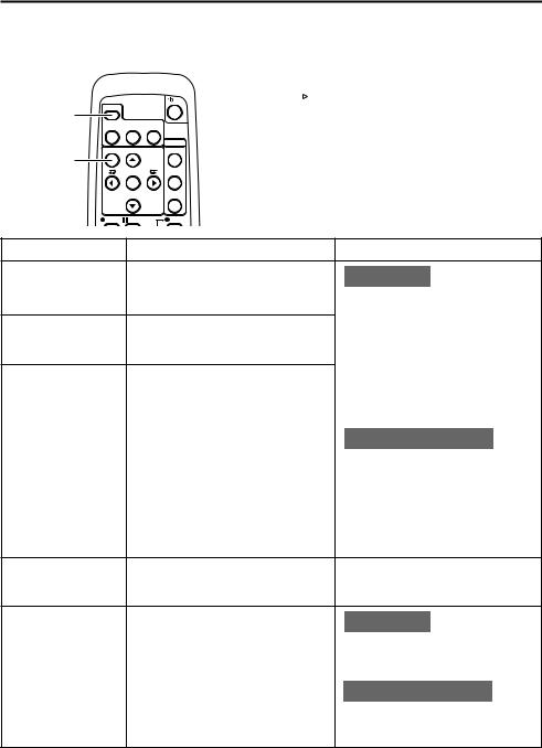
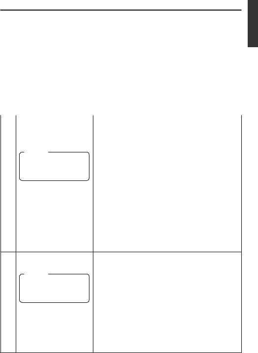
ON-SCREEN DISPLAY – Regarding on-screen display –
Besides E-E images and playback images, the monitor connected to the VIDEO LINE OUT terminal and Y/
C OUT terminal provides the following on-screen information.
Wireless remote controller |
DISPLAY (1/2) menu |
DISPLAY button
MENU button
DISPLAY |
|
|
BARS |
STILL |
BLANK |
MODE |
||
|
|
AUDIO |
MENU |
SEARCH+ |
MUTING |
|
|
OUT SEL. |
|
SET |
|
|
SEARCH– |
OUT LEV. |
A.DUB |
PAUSE |
REC |
|
– – – D I S P L A Y [ 1 / 2 ] – – – |
|
||
D I P L A Y |
O N |
|
|
|
|
|
|||
C O U N T E R P O S I . |
L OW E R - R |
|
||
T I M E |
C O D E |
O N |
|
|
V T R |
MO D E |
O N |
|
|
T A P E R E M A I N |
O F F |
|
||
T I M E D A T E |
D A T E + T M |
|
||
A U D I O I N F O . |
C H + R A T E |
|
||
N E X T |
P A G E |
|
|
|
P A G E |
B A C K |
|
|
|
|
|
|
|
|
Set at ON or AUTO
On-screen display |
Contents |
|
Method |
Status display |
It displays the setting status of date/ |
Main unit |
|
|
time, time code and VTR operation |
Set the DISPLAY item of the DISPLAY |
|
|
mode. |
||
|
(1/2) menu as follows: |
||
|
|
||
Event display |
It displays the operating status of the |
ON |
: Always display. Depending |
|
on the items, Event and |
||
|
blank search, index recording/search, |
|
|
|
|
Alarm displays are shown for |
|
|
or the wireless remote control. |
|
|
|
|
about 3 seconds. |
|
|
|
|
|
Alarm display |
It displays alarm messages upon op- |
AUTO |
: It displays for about 4 sec- |
|
eration errors or if the unit is in a poor |
|
onds after switching between |
|
state for operation. |
|
modes. |
|
|
OFF |
: No on-screen display. |
|
|
Remote controller |
|
|
|
The display can be turned ON/OFF |
|
|
|
with the DISPLAY button. Each time |
|
|
|
the DISPLAY button is pressed, the |
|
|
|
display mode changes in the follow- |
|
|
|
ing sequence: ON (Always display) |
|
|
|
¥AUTO ¥ OFF. |
|
|
|
*The settings for the DISPLAY menu |
|
|
|
items will also change accordingly. |
|
Warning display |
It displays warning messages with er- |
It is displayed automatically when |
|
|
ror codes in the event of VTR anoma- |
anomalies happen. |
|
|
lies. ( Page 66) |
|
|
Menu display |
It displays the menu setting screen. |
Main unit |
|
|
( Page 53) |
If no cassette is loaded and the EJECT |
|
|
|
||
|
|
button is pressed for at least 2 sec- |
|
|
|
onds, the menu will be displayed. |
|
|
|
Remote controller |
|
|
|
If the unit is in the STOP mode and |
|
|
|
the MENU button is pressed, the menu |
|
|
|
screen will be displayed. |
|
E-18
ON-SCREEN DISPLAY – Status display –
Status display: It displays the current settings and operating status.
1
|
|
|
|
|
|
|
|
|
|
|
|
|
|
|
|
|
|
|
|
|
|
|
|
|
|
|
|
|
|
|
|
|
|
|
|
|
|
|
|
|
|
|
|
|
|
|
3 2 K C H – 1 / 2 |
S P 0 0 0 m i n |
|
|
|
||||
|
2 |
|
|
|
1 0 / 1 0 / 0 2 |
S T A N D B Y - O F F |
|
|
|
||||
|
|
|
|
|
|
|
|||||||
|
|
|
|
1 2 : 0 0 : 0 0 |
T C R 0 2 : 0 0 : 0 0 : 0 0 |
|
|
|
|||||
|
|
|
|
|
|
|
|
||||||
|
|
|
|
|
|
|
|
|
|
|
|
|
|
|
|
|
|
|
|
|
|
|
|
|
|
|
|
|
|
|
|
|
|
|
|
|
|
|
|||
No. |
Item |
|
|
|
|
|
|
Content |
|
||||
|
|
|
|
|
|||||||||
1 |
Sampling frequency/audio |
• Sampling frequency |
|
||||||||||
|
output CH |
|
|
|
|
|
During recording, the setting value of the AUDIO MODE item |
|
|||||
|
|
|
|
|
|
|
|
|
of the AUDIO/VIDEO menu is displayed (32K or 48K). |
|
|||
|
Memo |
|
|
|
|
|
During playback, the sampling frequency of the sound re- |
|
|||||
|
|
|
|
|
|
corded on the tape is displayed (32K, 48K, 44.1K). |
|
||||||
|
If the time code display po- |
|
During DV signal input, the sampling frequency of the sound |
|
|||||||||
|
sition is set to the upper left, |
|
input is displayed. |
|
|||||||||
|
this item will be displayed on |
• A.LOCK |
|
||||||||||
|
the lower right. |
|
|
|
|
|
|||||||
|
|
|
|
|
|
Lights up when the video and audio sampling clocks (at |
|
||||||
|
|
|
|
|
|
|
|
|
|
||||
|
|
|
|
|
|
|
|
|
48kHz) are synchronized in the PLAY mode. |
|
|||
|
|
|
|
|
|
|
|
|
Lights up in the RECORDING mode and EE mode. |
|
|||
|
|
|
|
|
|
|
|
|
Does not light up when the sampling rate is 32kHz or 44.1 |
|
|||
|
|
|
|
|
|
|
|
|
kHz. |
|
|
|
|
•Audio output channel
During recording, the audio channel recorded on the tape is displayed.
During playback, the audio channel output from the AUDIO OUT terminal is displayed (CH1/2, CH3/4, MIX). (only in 32K mode)
•The AUDIO INFO. item of the DISPLAY menu can be set to activate/deactivate the display.
2 |
Date/time |
• It displays the date (DD/MM/YY) and time (HR:MM:SS). |
|
|
• When the unit is in the RECORDING or STOP mode, it dis- |
|
Memo |
plays the data of the built-in clock. |
|
• During playback, fast forward or rewind, the data recorded |
|
|
If the display position of the |
|
|
on the tape is displayed. |
|
|
time code is set to the lower |
• During DV signal recording, the data from the DV terminal is |
|
left, this item will be dis- |
|
|
displayed. If the REC button is pressed in the STOP mode, |
|
|
played on the lower right. |
|
|
the input data from the DV terminal will be displayed. |
|
|
|
|
|
|
• The style for displaying the date and time can be selected |
|
|
from the DATE STYLE and TIME STYLE items of the DIS- |
|
|
PLAY menu. |
|
|
• The TIME/DATE setting of the DISPLAY menu can be set to |
|
|
turn on/off the date and time display or to select the style. |
|
|
• When the data/time is not set, “– –” will be displayed. |
|
|
If a tape with no date and time data is played, "– –" will be |
|
|
displayed. |
E-19

ON-SCREEN DISPLAY – Status display – (continued)
|
|
3 2 K C H – 1 / 2 |
S P 0 0 0 m i n |
|
|
5 |
|||||||
|
|
|
|
||||||||||
|
|
1 0 / 1 0 / 0 2 |
|
S T A N D B Y - O F F |
|
|
4 |
||||||
|
|
|
|
||||||||||
|
|
1 2 : 0 0 : 0 0 |
T C R 0 2 : 0 0 : 0 0 : 0 0 |
|
|
|
|||||||
|
|
|
|
|
|
|
|
|
|
|
|
|
|
|
|
|
|
|
|
|
|
|
|
|
|
|
|
|
|
|
|
|
|
|
|
|
|
|
|
|
|
|
|
|
3 |
|
|
|
|
|
|
|
|
||
|
|
|
|
|
|
|
|
|
|
|
|
|
|
No. |
Item |
|
|
|
|
|
|
|
Content |
||||
|
|
|
|
|
|
|
|
|
|
|
|
|
|
3 |
Time code |
• It displays the time codes (hour, minute, second and frame). |
|||||||||||
|
|
|
During playback, the time codes recorded on the tape are |
||||||||||
|
|
|
displayed. |
|
|
|
|
|
|
|
|
||
|
|
|
|
TCR |
: time code reader data |
||||||||
|
|
|
|
TCG |
: time code generator data |
||||||||
|
|
|
|
DTCG : time code data input from a DV IN terminal |
|||||||||
|
|
|
• The symbols for the second and frame differ according to the |
||||||||||
|
|
|
framing modes. (NTSC only) |
||||||||||
|
|
|
00 : 00 : 00 |
|
|
00 |
|
|
|
||||
|
|
|
: |
|
|
|
|||||||
|
|
|
|
|
|
|
|
|
|
|
dot (.) is used for a dropped frame. |
||
|
|
|
|
|
|
|
|
|
|
¥ colon (:) is used for a non-dropped |
|||
|
|
|
|
|
|
|
|
|
|
||||
|
|
|
|
|
|
|
|
|
|
|
frame. |
||
|
|
|
• The time code display position can be set via the COUNTER |
||||||||||
|
|
|
POSI. item of the DISPLAY menu. |
||||||||||
|
|
|
• The TIME CODE item can be set to turn on/off the time code |
||||||||||
|
|
|
display. |
|
|
|
|
|
|
|
|
||
|
|
|
• The user’s bit is not displayed. |
||||||||||
|
|
|
|
|
|
|
|
|
|
|
|
|
|
4 |
VTR operation mode |
It displays the VTR operation modes, including: |
|||||||||||
|
|
|
PLAY, EJECT, FF, REW, STANDBY-ON, STANDBY-OFF, STILL, |
||||||||||
|
|
|
REC, REC PAUSE, A. DUB, A. DUB PAUSE, SHTL (shuttle |
||||||||||
|
|
|
search), JOG (F.ADV, R.ADV), BLANK SRH (blank search), |
||||||||||
|
|
|
NO CASSETTE (cassette not loaded), OPERATE OFF. |
||||||||||
|
|
|
When SHTL or JOG is displayed, the speed will also be dis- |
||||||||||
|
|
|
played at the same time. |
|
|
|
|||||||
|
|
|
• The VTR MODE item of the DISPLAY menu can be set to |
||||||||||
|
|
|
turn on/off the VTR operation mode display. |
||||||||||
|
|
|
|
|
|
|
|||||||
5 |
Remaining tape |
It displays the remaining tape duration (minutes). |
|||||||||||
|
|
|
If it is not identified, “ – – – ” is displayed. |
||||||||||
|
Memo |
• The TAPE REMAIN item in the DISPLAY menu can be set to |
|||||||||||
|
If the display position of the |
turn on/off the remaining tape duration display. |
|||||||||||
|
• The SP display disappears when the DVCAM cassette is |
||||||||||||
|
time code is set to the upper |
||||||||||||
|
right, this item will be dis- |
being played back. |
|
|
|
||||||||
|
played on the lower right. |
• Please use the remaining tape time as a gauge. |
|||||||||||
|
|
|
|||||||||||
|
|
|
|
|
|
|
|
|
|
|
|
|
|
E-20
ON-SCREEN DISPLAY – Event display –
Event display : When a specific function is in activation or when the operation status is changed with the remote controller, etc, the events will be displayed at the positions shown below.
|
|
3 2 K C H – 1 / 2 |
S P 0 0 0 m i n |
||
A |
|
|
|
|
|
|
|
B L A N K S E A R C H |
|
||
|
|
||||
B |
|
|
|
||
|
|
I N D E X D E T E C T E D |
|
||
|
|
||||
|
|
1 0 / 1 0 / 0 2 |
S T A N D B Y - O F F |
||
|
|
1 2 : 0 0 : 0 0 |
T C R 0 2 : 0 0 : 0 0 : 0 0 |
||
|
|
|
|
|
|
Display at position A
...Operation in progress
Display |
Contents |
|
|
BLANK SEARCH |
Blank search in progress. |
|
|
INDEX + 1 |
Index search in progress. |
|
The number indicates the |
|
index search position. |
|
|
INDEX MARK |
When an index is written on |
|
the tape during recording. |
|
|
Display at position B
...Display for about 3 seconds
Display |
Contents |
|
|
INDEX DETECTED |
Index is found during an in- |
|
dex repeat operation. |
|
|
VIDEO END |
Video end is found during a |
DETECTED |
video end repeat operation. |
|
|
AUDIO MUTING |
Audio is muted with the re- |
ON |
mote controller. |
|
|
AUDIO MUTING |
Audio is de-muted with the |
OFF |
remote controller. |
|
|
Display |
Contents |
|
|
|
|
AUDIO OUT |
The standard level of the |
|
LEVEL NORM |
playback or EE audio level is |
|
|
set to NORMAL or ATT with |
|
AUDIO OUT |
|
|
the remote controller. |
|
|
LEVEL ATT |
|
|
|
|
|
AUDIO OUT CH-1/2 |
The playback audio channel is |
|
|
set to CH1/2, CH3/4 or MIX |
|
AUDIO OUT CH-3/4 |
|
|
with the remote controller. |
|
|
|
|
|
AUDIO OUT MIX |
|
|
|
|
|
DISPLAY ON |
The on-screen display is |
|
|
turned on with the remote |
|
|
controller. |
|
|
|
|
DISPLAY AUTO |
The on-screen display is set |
|
|
to AUTO with the remote |
|
|
controller. In the AUTO |
|
|
mode, the on-screen display |
|
|
is shown for about 4 seconds |
|
|
between mode switches. |
|
|
|
|
DISPLAY OFF |
The on-screen display is set |
|
|
to OFF with the remote con- |
|
|
troller. |
|
|
|
|
FIELD STEP |
Field by field advance play- |
|
|
back is selected with the re- |
|
|
mote controller. |
|
|
|
|
1ST FIELD STILL |
When still or frame advance |
|
|
playback is selected with the |
|
|
remote controller, the type of |
|
|
still image is displayed. |
|
2ND FIELD STILL |
|
|
• 1st FIELD STILL |
|
|
|
|
|
|
• 2nd FIELD STILL |
|
|
• FRAME STILL |
|
|
|
|
FRAME STILL |
|
|
|
|
|
E-21

ON-SCREEN DISPLAY – Alarm display –
Alarm display : Alarm messages are displayed as shown below, when an operation error has occurred or when the unit is in a poor condition for operation. E.g., dirty head.
Display |
Contents |
LOW VOLTAGE |
The ideoy hear is dirt |
The voltage of the DC input power is loConinured oper36.9(atio will bar)-14DCingn the unitton th |
HEAD CLEANING
REQUIRED!
OVERHEATING!
E-22
Loading...