


 Loading...
AV-21F3
AV-21FR3
AV-21FMG3B
SERVICE MANUAL
COLOUR TELEVISION
AV-21F3
AV-21FR3 AV-21FMG3B
BASIC CHASSIS
CG
[ RM-C90 ] [ RM-C364GY] [RM-C364]
CONTENTS
!SPECIFICATIONS 2
!SAFETY PRECAUTIONS 3
!FEATURES 4
!FUNCTIONS 5
!MAIN DIFFERENCE LIST 7
!SPECIFIC SERVICE INSTRUCTIONS 8
!SERVICE ADJUSTMENTS 15
!PARTS LIST 33
OPERATING INSTRUCTIONS
STANDARD CIRCUIT DIAGRAM 2-1
1 |
COPYRIGHT © 2002 VICTOR COMPANY OF JAPAN, LTD. |
No. 52024 |
|
|
Jun. 2002 |
AV-21F3
AV-21FR3
AV-21FMG3B
SPECIFICATIONS
ITEM |
CONT ENTS |
||||||||||
|
|
|
|
|
|
|
|
||||
AV-21F3 |
AV-21FMG3B |
||||||||||
|
|
|
|||||||||
|
|
|
AV-21FR3 |
||||||||
|
|
|
|
|
|
|
|
|
|
||
|
|
|
|
|
|
|
|
|
|
|
|
Dimensions(W×H×D) |
619mm×458mm×486.5mm |
|
|
|
|
|
|
|
|||
|
|
|
|
|
|
|
|||||
Mass |
|
|
22kg |
|
|
|
|
|
|
|
|
|
|
|
|
|
|
|
|
|
|||
|
|
|
|
|
|
|
|
|
|
|
|
TV RF System |
|
|
B/G, I, D/K |
B/G, I, D/K,M |
|||||||
|
|
RF Mode |
PAL / SECAM |
PAL / SECAM / NTSC3.58 / NTSC4.43 |
|||||||
Colour System |
|
||||||||||
|
VIDEO Mode |
PAL / SECAM / NTSC3.58 / NTSC4.43 |
|
|
|
|
|
|
|
||
|
|
|
|
|
|
|
|
|
|||
Teletext System |
|
|
FLOP (Only for AV-21FR3) |
× |
|
|
|
||||
|
|
|
|
|
|
|
|
|
|
|
|
Picture Tube |
|
|
Visible size: 51cm measured diagonally |
|
|
|
|
|
|
|
|
|
|
|
|
|
|
|
|
|
|||
High Voltage |
|
|
26.5kV±1.5kV(at zero beam current) |
|
|
|
|
|
|
|
|
|
|
|
|
|
|
|
|
|
|||
|
|
|
|
|
|
|
|
|
|
||
Receiving Frequency VHF (VL) |
46.25MHz 168.25MHz |
|
|
|
|
|
|
|
|||
|
|
|
|
|
|
|
|||||
|
|
VHF (VH) |
175.25MHz 463.25MHz |
|
|
|
|
|
|
|
|
|
|
|
|
|
|
|
|
|
|||
|
|
UHF |
471.25MHz 863.25MHz |
|
|
|
|
|
|
|
|
|
|
|
|
|
|
|
|
|
|||
|
|
|
Cable TVs of Mid (X-Z, S1-S10) |
|
|
|
|
|
|
|
|
|
|
CATV |
Super (S11-S20) & Hyper (S21-S41) |
|
|
|
|
|
|
|
|
|
|
|
|
|
|
|
|
|
|||
|
|
|
bands receivable |
|
|
|
|
|
|
|
|
Intermediate |
|
VIF Carrier |
38.0MHz |
|
|
|
|
|
|
|
|
|
|
|
|
|
|
|
|
||||
|
|
32.5MHz (5.5MHz) |
32.5MHz(5.5MHz) /33.5MHz (4.5MHz) |
||||||||
Frequency |
|
|
|||||||||
|
SIF Carrier |
31.5MHz (6.5MHz) |
31.5MHz (6.5MHz) |
||||||||
|
|
||||||||||
|
|
|
32.0MHz (6.0MHz) |
32.0MHz (6.0MHz) |
|||||||
|
|
|
PAL (4.43MHz), |
|
|
|
|
|
|
|
|
Colour Sub Carrier Frequency |
SECAM (4.40625MHz / 4.25MHz) |
|
|
|
|
|
|
|
|||
|
|
|
|
|
|
|
|||||
|
|
|
NTSC (3.58MHz / 4.43MHz) |
|
|
|
|
|
|
|
|
|
|
AC110 240V, 50 / 60Hz |
|
|
|
|
|
|
|
||
Power Input |
Rated Voltage |
|
|
|
|
|
|
|
|||
|
|
|
|
|
|
|
|||||
|
|
|
|
|
|
|
|
|
|
|
|
Power Consumption |
90W (Max) / 60W(Avg) |
|
|
|
|
|
|
|
|||
|
|
|
|
|
|
|
|||||
|
|
|
|
|
|
|
|
|
|
|
|
Speaker |
|
|
6cm×12 cm, Oval type×2 |
|
|
|
|
|
|
|
|
|
|
|
|
|
|
|
|
|
|||
Audio Output |
|
|
3W (monaural) |
|
|
|
|
|
|
|
|
|
|
|
|
|
|
|
|
|
|||
|
|
|
|
|
|
|
|
|
|||
Aerial Input Terminal |
75Ω Unbalanced |
|
|
|
|
|
|
|
|||
|
|
|
|
|
|
|
|||||
|
|
|
|
|
|
|
|
|
|
||
Input |
Video |
1V(p-p), 75Ω (Front / Rear) |
|
|
|
|
|
|
|
||
|
|
|
|
|
|
|
|||||
|
Audio |
500mV(rms) (-4dBs), High impedance, |
|
|
|
|
|
|
|
||
|
RCA×2 (Front / Rear) |
|
|
|
|
|
|
|
|||
|
|
|
|
|
|
|
|
|
|
||
Output |
Video |
1V(p-p), 75Ω |
|
|
|
|
|
|
|
||
|
|
|
|
|
|
|
|||||
|
Audio |
500mV(rms) (-4dBs), Low impedance, |
|
|
|
|
|
|
|
||
|
|
|
|
|
|
|
|
||||
Headphone jack |
|
|
3.5mm mini jack |
|
|
|
|
|
|
|
|
|
|
|
|
|
|
|
|
|
|||
|
|
|
|
|
|
|
|
|
|
|
|
|
|
|
[AV-21F3] |
RM-C364 |
|||||||
Remote Control Unit |
: RM-C364GY |
(Battery size : AA / R06 / UM-3×2) |
|||||||||
[AV-21FR3] |
|
|
|
|
|
|
|
||||
|
|
|
|
|
|
|
|
|
|
||
|
|
|
: RM-C90 |
|
|
|
|
|
|
|
|
|
|
|
(Battery size : AA / R06 / UM-3×2) |
|
|
|
|
|
|
|
|
|
|
|
|
|
|
|
|
|
|
|
|
Design and specifications are subject to change without notice.
2 |
No. 52024 |
AV-21F3
AV-21FR3
AV-21FMG3B
SAFETY PRECAUTIONS
1.The design of this product contains special hardware, many circuits and components specially for safety purposes. For continued protection, no changes should be made to the original design unless authorized in writing by the manufacturer.
Replacement parts must be identical to those used in the original circuits. Service should be performed by qualified personnel only.
2.Alterations of the design or circuitry of the products should not be made. Any design alterations or additions will void the manufacturer's warranty and will further relieve the manufacturer of responsibility for personal injury or property damage resulting therefrom.
3.Many electrical and mechanical parts in the products have special safety-related characteristics. T hese characteristics are often not evident from visual inspection nor can the protection afforded by them necessarily be obtained by using replacement components rated for higher voltage, wattage, etc. Replacement parts which have these special safety characteristics are
identified in the parts list of Service manual. Electrical components having su ch features are identified by shading on the schematics and by (!) on the parts list in Service manual. The use of a substitute replacement which does not have the same safety characteristics as the recommended
replacement part shown in the parts list of Service manual may cause shock, fire, or other hazards .
4.Do n't short between the LIVE side ground and ISOL ATED (NEUTRAL) side ground or EARTH side ground when
repairing.
Some model's power circuit is partly different in the GND. The difference of the GND is shown by the LIVE : (") side GND, the ISOLATED(NEUTRAL) : (#) side GND and EARTH : ($) side GND. Don't short between the LIVE side GND and
ISOLATED(NEUTRAL) side GND or EARTH side GND and never measure with a measuring apparatus (oscilloscope etc.) the LIVE side GND and ISOLATED(NEUTRAL) side GND or EARTH side GND at the same time.
If above note will not be kept, a fuse or any parts will be broken.
5.If any repair has been made to the chassis, it is recommended that the B1 setting should be checked or adjusted (See ADJUSTMENT OF B1 POWER SUPPLY).
6.The high voltage applied to the picture tube must conform with
that specified in Service manual. Excessive high voltage can cause an increase in X-Ray emission, arcing and possible component damage, therefore operation under excessive high voltage conditions should be kept to a minimum, or should be prevented. If severe arcing occurs, remove the AC power
immediately and determine the cause by visual inspection (incorrect installation, cracked or melted high voltage harness, poor soldering, etc.). To maintain the proper minimum level of soft X-Ray emission, components in the high voltage circuitry including the picture tube must be the exact replacements or
alternatives approved by the manufacturer of the complete product.
7.Do not check high voltage by drawing an arc. Use a high voltage meter or a high voltage probe with a VTVM. Discharge the picture tube before attempting meter connection, by connecting
a clip lead to the ground frame and connecting the other end of the lead through a 10kΩ 2W resistor to the anode button.
8.When service is required, observe the original lead dress. Extra precaution should be given to assure correct lead dress in the high voltage circuit area. W here a short circuit has occurred, those components that indicate evidence of overheating should
be replaced. Always use the manufacturer's replacement components.
9.Isolation Check
(Safety for Electrical Shock Hazard)
After re-assembling the product, always perform an isolation check on the exposed metal parts of the cabinet (antenna
terminals, video/audio input and output terminals, Control knobs, metal cabinet, screwheads, earphone jack, control shafts, etc.) to be sure the product is safe to operate without danger of electrical shock.
(1)Dielectric Strength Test
The isolation between the AC primary circuit and all metal parts exposed to the user, particularly any exposed metal part having a return path to the chassis should withstand a voltage of 3000V AC (r.m.s.) for a period of one second.
(. . . . Withstand a voltage of 1100V AC (r.m.s.) to an appliance
rated up to 120V, and 3000V AC (r.m.s.) to an appliance rated 200V or more, for a period of one second.)
This method of test requires a test equipment not generally found in the service trade.
(2)Leakage Current Check
Plug the AC line cord directly into the AC outlet (do not use a line
isolation transformer during this check.). Using a " Leakage Current Tester", measure the leakage current from each exposed metal part of the cabinet, particularly any exposed metal part having a return path to the chassis, to a known good earth ground (water pipe, etc.). Any leakage current must not exceed
0.5mA AC (r.m.s.).
However, in tropical area, this must not exceed 0.2mA AC (r.m.s.).
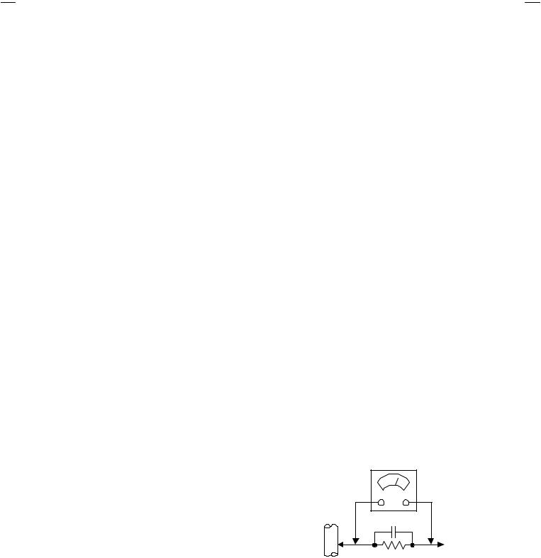
" Alternate Check Method
Plug the AC line cord directly into the AC outlet (do not use a line
isolation transformer during this check.). Use an AC voltmeter having 1000 ohms per volt or more sensitivity in the following manner. Connect a 1500Ω 10W resistor paralleled by a 0.15µF
AC-type capacitor between an exposed metal part and a known good earth ground (water pipe, etc.). Measure the AC voltage across the resistor with the AC voltmeter. Move the resistor connection to each exposed metal part, particularly any exposed
metal part having a return path to the chassis, and measure the AC voltage across the resistor. Now, reverse the plug in the AC outlet and repeat each measurement. Any voltage measured must not exceed 0.75V AC (r.m.s.). This corresponds to 0.5mA AC (r.m.s.).
However, in tropical area, this must not exceed 0.3V AC ( r.m.s.). This corresponds to 0.2mA AC (r.m.s.).
AC VOLTMETER (HAVING 1000 Ω/V,
OR MOR E SENSITIVITY)
0.15μF AC-TYPE
PLACE THIS PROBE
ON EACH EXPOSED
1500 Ω 10W |
METAL PART |
GOOD EARTH GROUND |
|
No.52024 |
3 |

AV-21F3
AV-21FR3
AV-21FMG3B
FEATURES
"New chassis design enables use of an interactive on-screen control.
"Wide range voltage (110V 240V) AC power input.
"With AUDIO / VIDEO INPUT & OUTPUT terminal.
"MUTING button can reduce the audio level to zero instantly.
"Functional remote control to operate T V set (for channel select, volume control, power ON/OFF, etc.) from a distance.
"I2C bus control utilizes single chip ICs for IF, V/C, DEF. VSM PRESET, PRESET & SETUP TOUR.
"By means of AUTO PROGRAM, the TV stations can be selected automatically and the TV channels can also be rearranged automatically.
"The TELETEXT SYSTEM has a built-in FLOP system. (Only for AV-21FR3)
"Built-in ECO MODE (ECONOMY, ECOLOGY)
In accordance with the brightness in a room, the brightness and / of contrast of the picture can be adjusted automatically to make the optimum picture which is easy on the eye.
"Built – in ON TIMER, RETURN + & CHILD LOCK.
SYSTEM BLOCK DIAGRAM
"
|
|
|
|
|
|
|
|
IC301 |
|
|
|
|
|
|||
|
|
|
|
|
|
|
|
TU001 |
||||||||
|
|
|
|
|
|
|
|
VIDEO/CHROMA |
|
|
||||||
|
|
|
|
|
|
|
|
DECORDER |
|
|
TUNER |
|||||
IC702 |
|
|
|
|
|
|||||||||||
|
|
|
|
|
|
|
|
|
|
|
||||||
|
|
|
|
|
|
|
|
|
|
|
|
|
|
|||
MEMORY |
|
IC701 |
|
|
|
|
|
|
|
|
|
|
|
|
||
|
|
|
|
|
|
|
|
|
|
|
|
|
|
|
|
|
|
|
|
|
|
|
|
|
|
SCL 1/SDA1 |
|
|
|
|
|
||
|
|
SCL 2/SDA2 |
MICRO |
TCL/TDA |
|
|
|
|
|
|||||||
|
|
COMPUTER |
|
|
|
|
|
|||||||||
|
|
|
|
|
|
|
|
|
|
|
|
|
|
|
|
|
|
|
|
|
|
|
|
|
|
|
|
|
|
|
|
|
|
|
|
|
|
|
|
|
|
|
|
|
|
|
|
|
|
|
|
|
|
|
|
|
|
|
IC821 |
|
|
|
|
|
|||
|
|
|
|
|
|
|
|
TEXT DECORDER |
|
|
|
|
|
|||
|
|
|
|
|
|
|
|
|
|
|
|
|
|
|
||
|
|
|
|
|
|
|
|
|
|
|
|
|
|
|||
|
|
|
|
|
|
|
|
Only for AV-21FR3 |
|
|
|
|
|
|
||
|
|
|
|
|
|
|
|
|
|
|
|
|
|
|
|
|
4 |
No. 52024 |
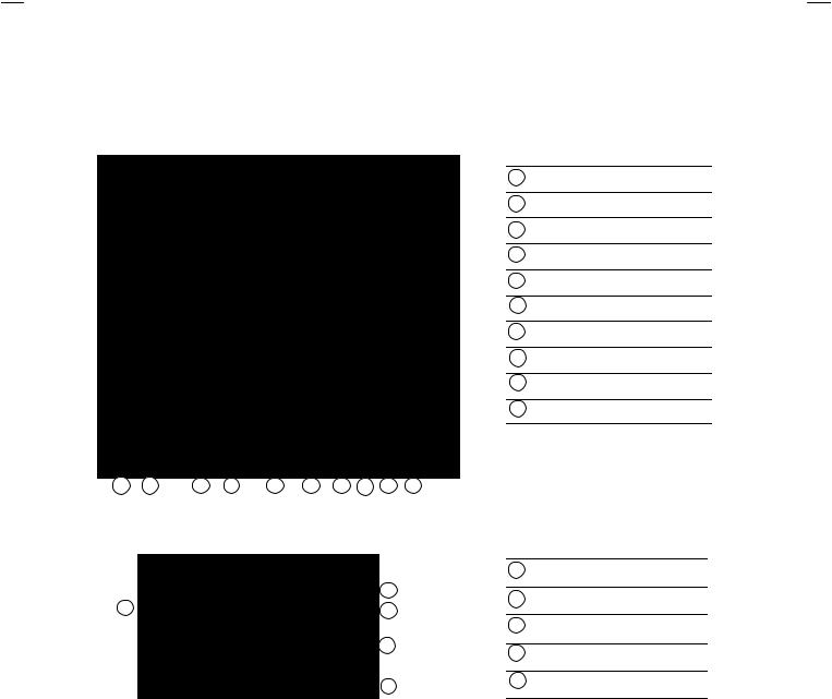
FUNCTIONS
■FRONT PANEL
10 |
9 |
1 |
2 |
3 |
4 |
5 |
6 |
7 |
8 |
■REAR TERMINAL
|
2 |
1 |
3 |
|
4 |
|
5 |
AV-21F3
AV-21FR3
AV-21FMG3B
1 MENU buttons
2 CHANNEL / buttons
3 VOLUME / buttons
4 AI ECO sensor
5 REMOTE CONTROL sensor
6 ON TIMER lamp
7 POWER lamp
8 MAIN POWER button
9 A/V INPUT terminal
10 HEADPHONE jack
1 ANT Terminal
2 VIDEO INPUT Terminal
3 VIDEO OUTPUT Terminal
4 AUDIO INPUT T erminal
5 AUDIO OUT PUT Terminal
No. 52024 |
5 |

AV-21F3
AV-21FR3
AV-21FMG3B
■REMOTE CONTROL UNIT
RM-C90 : AV-21FR3
1 |
11 |
2 |
12 |
3 |
13 |
|
|
4 |
14 |
|
|
5 |
|
6 |
15 |
|
|
7 |
|
8 |
16 |
9 |
17 |
|
|
10 |
|
|
18 |
RM-C364GY : AV-21F3 |
RM-C364 : AV-21FMG3B |
1 |
|
2 |
10 |
|
|
3 |
11 |
4 |
|
5 |
12 |
|
|
6 |
|
7 |
13 |
|
|
8 |
14 |
|
|
|
15 |
9 |
16 |
Except for difference in body colour, the Remote Control Unit RM-C364GY and RM-C364 have exactly the same Functions.
1ECO SENSOR key
2COLOUR SYSTEM key
3SOUND SYSTEM key
4DISPLAY key
5TV/VIDEO key
6OFF TIMER key
7PICTURE MODE key
8CHANNEL SCAN key
9RETURN key
10CHANNEL / key
11POWER key
12MUTING key
13TV/TEXT key
14MENU key
MENU ▲/▼ key
MENU / key
key
15Number (CH.) key
16/ key
17VOLUME / key
18Teletext key
1 ECO SENSOR key
2 SOUND SYSTEM key
3 COLOUR SYSTEM key
4 TV/VIDEO key
5 OFF TIMER key
6 CHANNEL SCAN key
7 RETURN key
8 DISPLAY key
9 CHANNEL key
10POWER key
11PICTURE MODE key
12Number (CH.) key
13/ key
14 |
MUTING key |
|
|
15 |
MENU key |
|
MENU ▲/▼ key |
|
MENU / key |
|
|
16 |
VOLUME / key |
|
|
6 |
No. 52024 |
AV-21F3
AV-21FR3
AV-21FMG3B
MAIN DIFFERENCE LIST
Part Name |
Main PWB |
Front Cabinet |
Remote Control Unit |
Pos,Serial Label |
|||
Model Name |
|||||||
|
|
|
|
|
|
||
|
|
|
|
|
|
|
|
AV-21F3 |
SCG-1411A-H2 |
LC10394-038A-H |
RM-C364GY-1H |
|
|
|
|
|
|
|
|||||
|
|
|
|
|
|
|
|
AV-21FR3 |
SCG-1402A-H2 |
LC10394-037A-H |
RM-C90-1H |
|
|
|
|
|
|
|
|||||
|
|
|
|
|
|
|
|
AV-21FMG3B |
SCG-1432A-H2 |
LC10394-039A-H |
RM-C364-1H |
CM47385-00B-H |
|||
|
|
|
|
|
|
|
|
|
Item |
|
|
Intermediate |
|
|
|
|
|
|
|
TV RF System |
Colour System |
Frequency |
Teletext System |
||||||
Model Name |
|
|||||||||
|
|
|
(SIF Carrier) |
|
|
|
|
|
||
|
|
|
|
|
|
|
|
|
||
|
|
|
|
32.5MHz (5.5MHz) |
|
|
|
|
|
|
AV-21F3 |
|
B/G, I, D/K |
PAL / SECAM |
31.5MHz (6.5MHz) |
|
|
|
|
|
|
|
|
|
|
|
|
|||||
|
|
|
|
32.0MHz (6.0MHz) |
|
|
|
|
|
|
AV-21FR3 |
|
B/G, I, D/K |
PAL / SECAM |
|
|
|
|
FLOP |
||
|
|
|
|
|
||||||
|
|
|
|
|
|
|
|
|
|
|
|
|
|
|
32.5MHz (5.5MHz) |
|
|
|
|
|
|
AV-21FMG3B |
|
B/G, I, D/K,&M |
PAL / SECAM |
33.5MHz (4.5MHz) |
|
|
|
|
|
|
|
NTSC3.58 / NTSC4.43 |
31.5MHz (6.5MHz) |
|
|
|
|
|
|||
|
|
|
|
|
|
|
|
|||
|
|
|
|
32.0MHz (6.0MHz) |
|
|
|
|
|
|
No. 52024 |
7 |

AV-21F3
AV-21FR3
AV-21FMG3B
SPECIFIC SERVICE INSTRUCTIONS
DISASSEMBLY PROCEDURE
REMOVING THE REAR COVER
1.Unplug the power plug.
2.As shown in figure, remove the 6 screws marked ! and a screw marked ".
3.Withdraw the rear cover toward you.
REMOVING THE MAIN PW BOARD
"After removing the rear cover.
1.Slightly raise the both sides of the MAIN PW BOARD by hand.
2.Withdraw the MAIN PW BOARD backward.
(If necessary, take off the wire clamp, connectors etc.)
REMOVING THE SPEAKER
"After removing the rear cover.
1.As shown in figure, remove the 2 screws marked #.
2.Follow the same steps when removing the other hand speaker.
CHECKING THE MAIN PW BOARD
1.To check the back side of the PW Board.
1)Pull out the MAIN PW Board. (Refer to REMOVING THE MAIN PW Board)
2)Erect the PW Board vertically so that you can easily check the back side of the PW Board.
[CAUTION]
"When erecting the PW Board, be careful so that there will be no contacting with other PW Board.
"Before turning on power, make sure that the CRT earth wire and other connector are properly connected.
WIRE CLAMPING AND CABLE TYING
1.Be sure to clamp the wire.
2.Never remove the cable tie used for tying the wires together. Should it be inadvertently removed, be sure to tie the wires with a new cable tie.
8 |
No. 52024 |
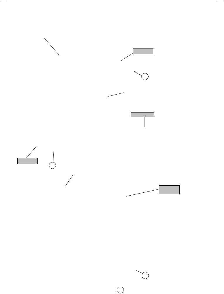
FRONT CABI.
SPEAKER
C
POWER
CORD
AV-21F3
AV-21FR3
AV-21FMG3B
SPEAKER
C
CRT SOCKET
PWB
MAIN PWB
REAR
COVER
B
 A
A
No. 52024 |
9 |
AV-21F3
AV-21FR3
AV-21FMG3B
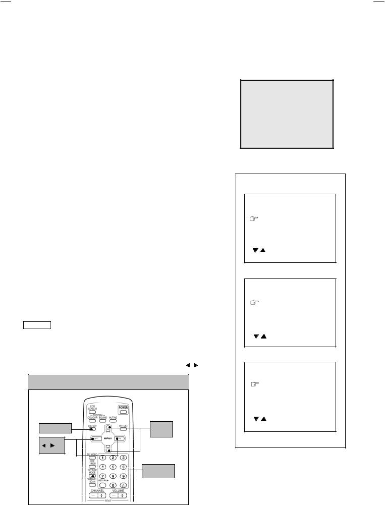
REPLACEMENT OF MEMORY ICs
1. MEMORY ICs
This model uses memory ICs. This memory IC data are for proper operation of the video and deflection circuits. When replacing memory ICs, be sure to use ICs written with the initial values of data.
2. PROCEDURE FOR REPLACING MEMORY ICs |
|
SERVICE MENU |
|
|
||||
(1) Power off |
|
|
|
|
||||
|
|
1.IF |
2.V/C |
|
|
|||
Switch the power off and disconnect the power plug from the wall outlet. |
|
|
||||||
3.DEF |
4.VSM PRESET |
|
||||||
(2) Replace ICs |
|
|
5.PRESET |
|
|
|||
|
|
6.SETUP TOUR OFF |
|
|
||||
Be sure to use memory ICs written with the initial data values. |
|
|
|
|||||
|
1-6 SELECT |
DISP : EXIT |
|
|||||
(3) Power on |
|
|
|
|||||
|
|
****** ***** |
**.*** |
|
||||
Connect the power plug into the wall outlet and switch the power on. |
|
|||||||
*** ** ** ** |
*** |
|
||||||
(4) Check and set SYSTEM CONSTANT SET |
|
|
|
|||||
|
|
|
|
|
|
|||
It must not adjust without adjustment signals. |
|
|
|
Fig.1 |
|
|
||
1) Press the DISPLAY key and the PICTURE MODE key of the REMOTE |
|
|
|
|
||||
CONTROL UNIT simultaneously. |
|
|
|
|
|
|
||
2) The SERVICE MENU screen of Fig. 1 will be displayed. |
|
|
|
|
|
|||
3) While the SERVICE MENU is displayed, again press the DISPLAY key and |
SYSTEM CONSTANT- |
|||||||
PICTURE MODE key simultaneously, and the SYSTEM CONSTANT SET |
||||||||
|
|
|
|
|||||
screen of Fig. 2 will be displayed. |
|
|
SYSTEM CONSTANT SET |
1 |
||||
4) Check the setting values of the SYSTEM CONSTANT SET of T able 1 If the |
||||||||
COLOUR |
: *** |
|
||||||
value is |
different, select the setting item with the MENU ▼/▲key, and set |
|
||||||
BILINGUAL |
: NO |
|
||||||
the correct value with the MENU - / + key. |
|
|
|
|||||
|
|
TUNER |
: MU |
|
||||
5) Press the DISPLAY key twice, and return to the normal screen. |
|
ECO SENSOR |
: YES |
|
||||
(5) Receive channel of setting |
|
|
LANGUAGE |
: *** |
|
|||
|
|
|
|
|
|
|||
Refer to |
the OPERATING INST RUCTIONS and set the receive channels |
/ |
: SELECT |
DISP : EXIT |
|
|||
(channels preset) as described |
|
|
- / + : OPERATE |
|
||||
|
|
|
|
|
|
|||
(6) User Setting |
|
|
|
|
|
|
||
Check the user setting value of Table 2, and if setting value is different, set |
SYSTEM CONSTANT- |
|||||||
the correct value. |
|
|
|
|
|
|
||
For setting, refer to the OPERATING INSTRUCTIONS. |
|
SYSTEM CONSTANT SET |
2 |
|||||
(7) Setting of SERVICE MENU |
|
|
B/B SOUND |
: OFF |
|
|||
Verify the setting items of the SERVICE MENU, and reset where necessary. |
LOCK |
: 180 |
|
|||||
For setting, refer to the SERVICE ADJUSTMENTS. |
|
COLOUR AUTO |
: NO |
|
||||
|
QSS |
: MINT |
|
|||||
|
|
|
|
|
||||
NOTE |
|
|
|
ALC |
: NO |
|
||
|
|
|
TEXT RATE |
: 20 |
|
|||
Although the key position of the RM-C90 remote control unit is different from |
|
|||||||
/ |
: SELECT |
|
|
|||||
|
|
|
|
|
|
|||
that of the RM-C364GY & RM-C364 remote control unit, the functions of both |
- / + : OPERATE |
DISP : EXIT |
|
|||||
units are the same So please use the attached diagram for the RM-C90 |
|
|
|
|
||||
remote control unit for the RM-C364GY & RM-C364. |
|
SYSTEM CONSTANT- |
||||||
By the way, MENU -/+ Key functions in the same manner as for |
/ key. |
|
|
|
|
|||
|
|
|
|
SYSTEMCONSTANT SET |
3 |
|||
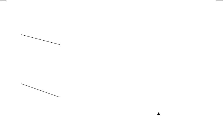
KEY ASSIGNMENT OF REMOTE CONTROL UNIT |
|
AMPTUNER |
: NO |
|
||||
|
|
|
|
VNR |
: YES |
|
||
|
|
|
|
TEXT TABLE |
: CYL |
|
||
|
|
|
|
VOLUM PWM |
: POS |
|
||
|
|
|
|
/ |
: SELECT |
|
|
|
DISPLAY key |
MENU |
|
- / + : OPERATE |
DISP : EXIT |
|
|||
▼/▲ key |
|
|
|
|
|
|||
|
|
|
|
|
|
|
||
MENU |
|
|
|
|
|
|
||
/ |
key |
|
|
|
|
|
|
|
|
|
|
|
|
Fig.2 |
|
||
NUMBERS
PICTURE |
|
|
key |
MODE key |
|
|
|
|
|
|
|
(RM-C90)
10 |
No. 52024 |
Loading...