


 Loading...
JVC AV-21BD5EES, AV-21BD5EPS, AV-21BD5EKIS, AV-21BD5EP, AV-21BD5EE Service Manual
...AV-21BD5EKI AV-21BD5EP AV-21BD5EE
AV-21BD5EKIS AV-21BD5EPS AV-21BD5EES
SERVICE MANUAL
COLOUR TELEVISION
AV-21BD5EKI / AV-21BD5EP / AV-21BD5EE AV-21BD5EKIS / AV-21BD5EPS / AV-21BD5EES
CONTENTS
!SPECIFICATIONS 1-2
!SAFETY PRECAUTIONS 1-5
!FUNCTIONS 1-6
!SPECIFIC SERVICE INSTRUCTIONS 1-8
!SERVICE ADJUSTMENTS 1-9STANDARD CIRCUIT DIAGRAM (APPENDIX) 2-1
!PARTS LIST 1-15
1 |
COPYRIGHT © 2000 VICTOR COMPANY OF JAPAN, LTD. |
No.51742 |
|
Jul. 2000 |
|
|
|

AV-21BD5EKI AV-21BD5EP AV-21BD5EE
AV-21BD5EKIS AV-21BD5EPS AV-21BD5EES
SPECIFICATIONS
Item |
Content |
|
||
|
|
|
|
|
|
|
|
|
|
TV RF SYSTEM |
B/G, I, D/K & L/L’ |
|
||
|
|
|
|
|
COLOUR STANDARD |
PAL / SECAM / NTSC (AV only) |
|
||
|
|
|
|
|
POWER INPUT |
AC 230V, 50Hz |
|
||
|
|
|
|
|
POWER CONSUMPTION |
49W / 3W (STBY) |
|
||
|
|
|
|
|
TELETEXT SYSTEM |
FLOF (Fastext) / TOP / WST (standard system) |
|
||
|
|
|
|
|
SOUND OUTPUT / SPEAKER |
7W / 8Ω (×2) |
|
||
|
|
|
|
|
PICTURE TUBE SIZE |
VISIBLE AREA 51cm (measured diagonally) |
|
||
|
|
|
|
|
ANTENNA INPUT |
75Ω Unbalanced |
|
||
|
|
|
|
|
INPUT / OUTPUT |
FRONT: RCA JACK (VIDEO / AUDIO) |
|
|
COMMON INPUT |
|
||||
REAR : 21-PIN EURO CONNECTOR (SCART)×2 |
|
|||
|
|
|
||
|
(VIDEO / AUDIO / RGB / S. VHS) |
|
|
|
|
|
|
|
|
INTERMEDIATE FREQUENCIES |
PIF : 38.9MHz (B/G, D/K, I, L) , 33.9MHz (L’) |
|
||
|
SIF : 33.4MHz (PAL / SECAM – B/G) |
|
||
|
32.9MHz (PAL / SECAM – I / I) |
|
||
|
32.4MHz (PAL / SECAM – D/K, SECAM – L) |
|
||
|
40.4MHz (SECAM – L’) |
|
||
|
SOUND SUBCARRIER : 5.5MHz (PAL / SECAM – B/G) |
|
||
|
6.0MHz (PAL / SECAM – I / I) |
|
||
|
6.5MHz (PAL / SECAM – D/K, SECAM – L) |
|||
|
6.5MHz (SECAM – L’) |
|
||
|
COLOUR SUBCARRIER : 4.43MHz (PAL) |
|
||
|
|
|||
|
4.250MHz, 4.406MHz (SECAM) |
|
||
|
|
|
|
|
REMOTE CONTROL |
RM-C71 [ Batt, AAA (R03) ] (EP, EPS, EE, EES) |
|
||
|
RM-C72 [ Batt, AAA (R03) ] (EKI, EKIS) |
|
||
|
|
|
|
|
DIMENSIONS (W×H×D) |
615mm×480mm×480mm |
|
||
|
|
|
|
|
MASS |
20.3kg |
|
||
|
|
|
|
|
Design & specifications are subject to change without notice.
1-2 |
No.51742 |

AV-21BD5EKI AV-21BD5EP AV-21BD5EE
AV-21BD5EKIS AV-21BD5EPS AV-21BD5EES
■21-pin Euro connector (SCART socket)
21Pin EURO-SCART 1:
Pin |
Signal Designation |
Matching Value |
|
No. |
|||
|
|
||
|
|
|
|
|
|
|
|
1 |
Audio Output Right |
0.5V(rms), Imp<1kΩ (RF 54% MOD) |
|
|
|
|
|
2 |
Audio Input Right |
0.5V(rms), Imp>10kΩ |
|
|
|
|
|
3 |
Audio Output!Left |
0.5V(rms), Imp<1kΩ (RF 54% MOD) |
|
|
|
|
|
4 |
Audio Earth |
|
|
|
|
|
|
5 |
Blue Earth |
|
|
|
|
|
|
6 |
Audio Input Left |
0.5V(rms), Imp>10kΩ |
|
|
|
|
|
7 |
Blue Input |
0.7V(p-p) ±0.1V, Imp75Ω |
|
|
|
|
|
8 |
Slow Switching |
TV : 0-2V, AV 16/9 : 4.5-7V, AV 4/3 : 9.5-12V, Imp>10kΩ |
|
|
|
|
|
9 |
Green Earth |
|
|
|
|
|
|
10 |
NC |
|
|
|
|
|
|
11 |
Green Input |
0.7V(p-p) ±0.1V, Imp 75Ω |
|
|
|
|
|
12 |
NC |
|
|
|
|
|
|
13 |
Red Earth |
|
|
|
|
|
|
14 |
Blanking Earth |
|
|
|
|
|
|
15 |
Red Input |
0.7V(p-p) ±0.1V, Imp 75Ω |
|
|
|
|
|
16 |
Fast Switching |
0-0.4V : Logic “0”, 1-3V : Logic “1”, Imp75Ω |
|
|
|
|
|
17 |
Video Out Earth |
|
|
|
|
|
|
18 |
Video In Earth |
|
|
|
|
|
|
19 |
Video Output |
1V(p-p) ±3dB, Imp75Ω |
|
|
|
|
|
20 |
Video Input |
1V(p-p) ±3dB, Imp75Ω |
|
|
|
|
|
21 |
Common Earth |
|
|
|
|
|
[Pin assignment]
|
1-3 |
No.51742 |

AV-21BD5EKI AV-21BD5EP AV-21BD5EE
AV-21BD5EKIS AV-21BD5EPS AV-21BD5EES
21Pin EURO-SCART 2 :
Pin |
Signal Designation |
Matching Value |
|
No. |
|||
|
|
||
|
|
|
|
|
|
|
|
1 |
NC |
|
|
|
|
|
|
2 |
Audio Intput!Right |
0.5V(rms), Imp<10kΩ |
|
|
|
|
|
3 |
NC |
|
|
|
|
|
|
4 |
Audio Earth |
|
|
|
|
|
|
5 |
Earth |
|
|
|
|
|
|
6 |
Audio Input Left |
0.5V(rms), Imp>10kΩ |
|
|
|
|
|
7 |
NC |
|
|
|
|
|
|
8 |
NC |
|
|
|
|
|
|
9 |
NC |
|
|
|
|
|
|
10 |
NC |
|
|
|
|
|
|
11 |
NC |
|
|
|
|
|
|
12 |
NC |
|
|
|
|
|
|
13 |
Earth |
|
|
|
|
|
|
14 |
Earth |
|
|
|
|
|
|
15 |
Chroma Input |
±3dB for a luminance signal of 1V(p-p) |
|
|
|
|
|
16 |
NC |
|
|
|
|
|
|
17 |
Earth |
|
|
|
|
|
|
18 |
Video In Earth |
|
|
|
|
|
|
19 |
NC |
|
|
|
|
|
|
20 |
Video Input, Y In. |
1V(p-p) ±3dB, Imp75Ω |
|
|
|
|
|
21 |
Common Earth |
|
|
|
|
|
[Pin assignment]
1-4 |
|
No.51742 |

AV-21BD5EKI AV-21BD5EP AV-21BD5EE
AV-21BD5EKIS AV-21BD5EPS AV-21BD5EES
SAFETY PRECAUTIONS
1.The design of this product contains special hardware, many circuits and components specially for safety purposes. For continued protection, no changes should be made to the original design unless authorized in writing by the manufacturer. Replacement parts must be identical to those used in the original circuits. Service should be performed by qualified personnel only.
2.Alterations of the design or circuitry of the products should not be made. Any design alterations or additions will void the manufacturer's warranty and will further relieve the manufacturer of responsibility for personal injury or property damage resulting therefrom.
3.Many electrical and mechanical parts in the products have special safety-related characteristics. These characteristics are often not evident from visual inspection nor can the protection afforded by them necessarily be obtained by using replacement components rated for higher voltage, wattage, etc. Replacement parts which have these special safety characteristics are identified in the parts list of Service manual.
Electrical components having such features are identified by shading on the schematics and by ( !) on the parts list in Service manual. The use of a substitute replacement which does not have the same safety characteristics as the recommended replacement part shown in the parts list of Service manual may cause shock, fire, or other hazards.
4.Don't short between the LIVE side ground and ISOLATED (NEUTRAL) side ground or EARTH side ground when repairing.
Some model's power circuit is partly different in the GND. The difference of the GND is shown by the LIVE : (") side GND, the ISOLATED(NEUTRAL) : (#) side GND and EARTH : ($) side GND. Don't short between the LIVE side GND and ISOLATED(NEUTRAL) side GND or EARTH side GND and never measure with a measuring apparatus (oscilloscope etc.) the LIVE side GND and ISOLATED(NEUTRAL) side GND or EARTH side GND at the same time.
If above note will not be kept, a fuse or any parts will be broken.
5.If any repair has been made to the chassis, it is recommended that the +B setting should be checked or adjusted (See +B ADJUSTMENT).
6.The high voltage applied to the picture tube must conform with that specified in Service manual. Excessive high voltage can cause an increase in X-Ray emission, arcing and possible component damage, therefore operation under excessive high voltage conditions should be kept to a minimum, or should be prevented. If severe arcing occurs, remove the AC power immediately and determine the cause by visual inspection (incorrect installation, cracked or melted high voltage harness, poor soldering, etc.). To maintain the proper minimum level of soft X-Ray emission, components in the high voltage circuitry including the picture tube must be the exact replacements or alternatives approved by the manufacturer of the complete product.
7.Do not check high voltage by drawing an arc. Use a high voltage meter or a high voltage probe with a VTVM. Discharge the picture tube before attempting meter connection, by connecting a clip lead to the ground frame and connecting the other end of the lead through a 10k" 2W resistor to the anode button.
8.When service is required, observe the original lead dress. Extra precaution should be given to assure correct lead dress in the high voltage circuit area. Where a short circuit has occurred, those components that indicate evidence of overheating should be replaced. Always use the manufacturer's replacement components.
No.51742 |
1-5 |

AV-21BD5EKI AV-21BD5EP AV-21BD5EE
AV-21BD5EKIS AV-21BD5EPS AV-21BD5EES
FUNCTIONS
LOCAL CONTROL
FRONT
MAIN POWER |
VIDEO |
AUDIO |
HEAD |
STAND-BY |
REMOTE AV BUTTON |
VOLUME |
PR (PROGRAM) |
BUTTON |
INPUT |
INPUT |
PHONE |
INDICATOR |
SENSOR |
DOWN/UP |
DOWN/UP |
|
|
|
|
|
|
BUTTONS |
BUTTONS |
BACK
AERIAL TERMINAL
SCART JACK 1(AV1)
SCART JACK 2(AV2)
1-6 |
No. 51742 |

AV-21BD5EKI AV-21BD5EP AV-21BD5EE
AV-21BD5EKIS AV-21BD5EPS AV-21BD5EES
REMOTE CONTROL
TV mode
1.POWER
2.NUMBER 0-9 / NUMBER
3.P.MODE / OK
4.AV
5.UP
6.RIGHT
7.MENU
8.DOWN
9.LEFT
10.MUTING
11.RECALL
12.SLEEP
13.Not used
14.MOVE
15.SKIP
16.TV / TEXT
17.DELETE
18.MODE
19.VCR /  / DVD switch
20.VCR / DVD Control buttons
TELETEXT mode
1.POWER
2.NUMBER 0-9
3.INDEX
4.Not used
5.UP
6.SUBPAGE
7.MENU
8.DOWN
9.HOLD
10.MUTING
11.REVEAL
12.SIZE
13.CANCEL
14.GREEN
15.RED
16.TV / TEXT
17.YELLOW
18.CYAN
19. VCR |
/ DVD switch |
20. Not used |
|
No. 51742 |
1-7 |

AV-21BD5EKI AV-21BD5EP AV-21BD5EE
AV-21BD5EKIS AV-21BD5EPS AV-21BD5EES
SPECIFIC SERVICE INSTRUCTIONS
DISASSEMBLY PROCEDURE
Note : Before starting work, disconnect the power plug from the wall outlet.
HOW TO REMOVE THE REAR COVER
1.Remove the 5 screws marked A.
2.Remove the rear cover backward.
CRT SOCKET PWB
A
CRT
SPEAKER
POWER SW. FBT
 TUNER
TUNER
PWB
FRONT CABINET
1-8 |
No.51742 |
AV-21BD5EKI AV-21BD5EP AV-21BD5EE
AV-21BD5EKIS AV-21BD5EPS AV-21BD5EES
SERVICE ADJUSTMENTS
BEFORE ADJUSTMENT AND MAINTENANCE
1.Don't short any two soldering points or connect any component while TV set is power on.
2.Withdraw power plug before maintenance.
3.In order to ensure safety all components replaced should be identical. (For further details, refer to the component name and component No. in PARTS LIST.)
4.Must be warm up the set for 30 minutes or more and degauss CRT thoroughly with demagnetizer coil before adjustment.
EQUIPMENT FOR ADJUSTMENT
1.Pattern Generator
2.Digital volt meter
3.Oscilloscope
4.Demagnetizer
5.Service remote controller (For repair service)
6.Remote controller (RM-C71 or RM-C72)
ADJUSTMENTS PROCEDURES
+B VOLTAGE CHECK
1.Receive a standard colour bar signal.
2.Connect digital volt meter between + of B1 Line circuit and GND.
3.Confirm that voltage is DC 123V # 2.0V.
(RM-C71) |
(RM-C72) |
|
|
|
|
|
|
Remote Controller |
|
Service Remote Controller |
|
No.51742 |
1-9 |
AV-21BD5EKI AV-21BD5EP AV-21BD5EE
AV-21BD5EKIS AV-21BD5EPS AV-21BD5EES
BASIC OPERATION OF SERVICE MENU
REMOTE CONTROLLER (RM-C71, RM-C72) How to ENTER and EXIT from service mode
1.Select the CH-91.
2.Press the MENU KEY of the remote control unit and select PICTURE from the MENU with the P.(▲)/ P.(▼) key of the remote control unit .
3.While pressing the P. MODE/OK KEY of the remote control unit, select "sharpness" from the MENU with the P.(▲)/ P.(▼) /
 -/
-/  + key. Then, set the set value of "sharpness" to "0" with the
  -/
-/  +KEY.
+KEY.
4.Press the MENU KEY of the remote control unit twice and return to the normal screen. To enter the SERVICE MODE, change the indication of RED, GREEN and MENU, in turn, with the key of the remote control unit.
5.When exiting from the SERVICE MODE, turn the power switch off.
How to set SERVICE MODE
1.Select the setting item you want to change with the P.(▲)/ P.(▼) key on the remote control unit. (The item you selected will be indicated by YELLOW on the display.)
2.When changing the set values, use the  -/
-/  +KEY on the remote control unit.
3.When the setting has been completed, turn the power switch off. (The changed set values are stored in memory.)
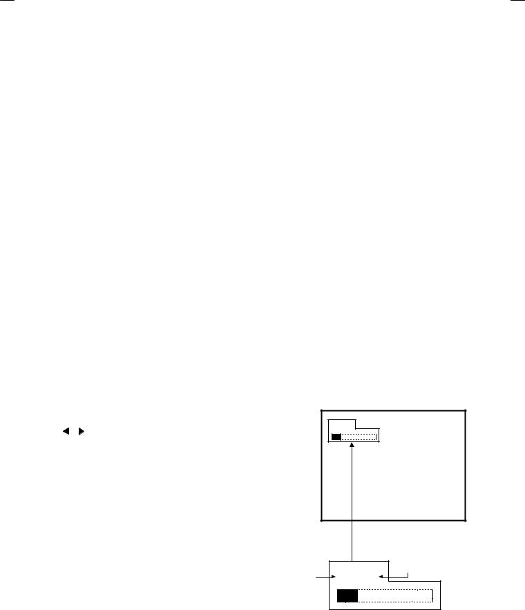
SERVICE MENU screen selection
Press the P.(▲)/ P.(▼) key select menu item. (The letters of the selected items are displayed in yellow)
Press the |
-/ |
+KEY setting the value item. |
AGC |
|
VS Cor |
Black R |
|
V Shift |
Black G |
|
H Width |
WP Red |
|
EW Parabo |
WP Green |
|
Up Corner |
WP Blue |
|
Dw Corner |
H Parall |
|
EW Trapez |
H Bow |
|
Option |
H Shift |
|
|
V Slope |
|
|
V Amp |
|
|
SERVICE
** Black R
|
|
screen |
|
SERVICE |
menu item |
Setting value |
** Black R |
|
1-10 |
No.51742 |
Loading...