


AV-2135EE
Table of contents
 Loading...
JVC AV-2135EE, AV-2135TEE, AV-21D3/D, AV-21DMG3, AV-21DMG3/-A Service Manual
...
3
3
SERVICE MANUAL
COLOUR TELEVISION
AV-21DMT3 / AV-21D3
AV-2135TEE / AV-2135EE
/D
AV-21DMT3/AV-21D
AV-2135TEE/AV-2135EE
AV-21DMG
BASIC CHASSIS
CG
AV-21DMG3
[ RM-C3 64GY ][ RM -C9 0 ]
CONTENTS
AV-21DMG3
/
/-A
!
SPECIFICATIONS
!
SAFETY PRECAUT IONS ・・・・・・・・・・・・・・・・・・・・・・・・・・・・・・・・
! FEATU RES・・・・・・・・・・・・・・・・・・・・・・・・・・・・・・・・
! FUNCTIONS ・・・・・・・・・・・・・・・・・・・・・・・・・・・・・・・・
!
MAIN DIFFERENCE LIST ・・・・・・・・・・・・・・・・・・・・・・・・・・・・・・・・
! SPECIFIC SERVICE INSTRUCTIONS ・・・・・・・・・・・・・・・・・・・・・・・・・・・・・・・・
!
SERVICE ADJUSTMENTS
!
PARTS LIST ・・・・・・・・・・・・・・・・・・・・・・・・・・・・・・・・
★ OPERAT ING INSTRUCTIONS
★ STAND ARD CIRCUIT DIAGRAM ・・・・・・・・・・・・・・・・・・・・・・・・・・・・・・・・
1
・・・・・・・・・・・・・・・・・・・・・・・・・・・・・・・・・・・・・・・・・・・・・・・・・・・・・・・・・・・・・・・・
・・・・・・・・・・・・・・・・・・・・・・・・・・・・・・・・・・・・・・・・・・・・・・・・・・・・・・・・・・・・・・・・
・・・・・・・・・・・・・・・・・・・・・・・・・・・・・・・・
・・・・・・・・・・・・・・・・・・・・・・・・・・・・・・・・・・・・・・・・・・・・・・・・・・・・・・・・・・・・・
・・・・・・・・・・・・・・・・・・・・・・・・・・・・・・・・・・・・・・・・・・・・・・・・・・・・・・・・・・・・・・・・
・・・・・・・・・・・・・・・・・・・・・・・・・・・・・・・・・・・・・・・・・・・・・・・・・・・・・・・
・・・・・・・・・・・・・・・・・・・・・・・・・・・・・・・・・・・・・・・・・・・・・・・・・・・・・・・・・・・・・・・・
・・・・・・・・・・・・・・・・・・・・・・・・・・・・・・・・・・・
・・・・・・・・・・・・・・・・・・・・・・・・・・・・・・・・・・・・・・・・・・・・・・・・・・・・・・・・・・・・・・・・
・・・・・・・・・・・・・・・・・・・・・・・・・・・・・・・・・・・・・・・・・・・・・・・・・・・・・・・・・・・・・・・・
・・・・・・・・・・・・・・・・・・・・・・・・・・・・・・・・・・・・・・・・・・・・・・・・・・・・・・・・・・・・・・・・
・・・・・・・・・・・・・・・・・・・・・・・・・・・・・・・・・・・・・・・・・・・・・・・・・・・・・・・
・・・・・・・・・・・・・・・・・・・・・・・・・・・・・・・・・・・・・・・・・・・・・・・・・・・・・・・・・・・・・・・・
・・・・・・・・・・・・・・・・・・・・・・・・・・・・・・・・・・・・・・・・・・・・・
・・・・・・・・・・・・・・・・・・・・・・・・・・・・・・・・・・・・・・・・・・・・・・・・・・・・・・・・・・・・・・・・
・・・・・・・・・・・・・・・・・・・・・・・・・・・・・・・・
・・・・・・・・・・・・・・・・・・・・・・・・・・・・・・・・・・・・・・・・・・・・・・・・・・・・・
・・・・・・・・・・・・・・・・・・・・・・・・・・・・・・・・・・・・・・・・・・・・・・・・・・・・・・・・・・・・・・・・
・・・・・・・・・・・・・・・・・・・・・・・・・・・・・・・・・・・・・・・・・・・・・・・・・・・・・・・・・・・・・・・・
・・・・・・・・・・・・・・・・・・・・・・・・・・・・・・・・・・・・・・・・・・・・・・・・・・・・・・・・・・・・・・・・
・・・・・・・・・・・・・・・・・・・・・・・・・・・・・・・・・・・・・・・・・・・・・・・・
・・・・・・・・・・・・・・・・・・・・・・・・・・・・・・・・・・・・・・・・・・・・・・・・・・・・・・・・・・・・・・・・
COPYRIGHT © 2002 VICTOR COMPANY OF JAPAN, LTD.
・・・・・・・・・・・・・・・・・・・・・・・・・・・・・
・・・・・・・・・・・・・・・・・・・・・・・・・・・・・・・・・・・・・・・・・・・・・・・・・・・・・・・・・・
・・・・・・・・・・・・・・・・・・・・・・・ 3
・・・・・・・・・・・・・・・・・・・・・・・・・・・・・・・・・・・・・・・・・・・・・・
・・・・・・・・・・・・・・・・・・・・・・・・・・・・・・・・・・
・・・・・・・・・・・・・・・・・・・・・・・・・・・・・・・・・・・・・・・・・・・・・・・・・・・・・・・・・・・・・・・・
・・・・・・・・・・・・・・・・・・・・・・・ 7
・・・・・・・・・・・・・・・・・・・・・・・・・・・・・・・・・・・・・・・・・・・・・・
・・・・・・・・・・・・・・・・・・・・・
・・・・・・・・・・・・・・・・・・・・・・・・・・・・・・・・・・・・・・・・・・
・・・・・・・・・・・・・・・・・・・・・・・・・・・・・・・・・・・・ 33
・・・・・・・・・・・・・・・・・・・・・・・・・・・・・・・・・・・・・・・・・・・・・・・・・・・・・・・・・・・・・・・・
・・・ 4
・・・・・・
・・ 5
・・・・
・・・・・・・・・・・・・ 8
・・・・・・・・・・・・・・・・・・・・・・・・・・
15
・・・・・・・・・・・・・・・・2-1
・・・・・・・・・・・・・・・・・・・・・・・・・・・・・・・・
2
No. 52023
Jun. 2002
A
V-21DMT3/AV-21D3
A
A
V-2135TEE/AV-2135EE
V-21DMG3
SPECIFICATIONS
CONT ENTS
ITEM AV-21DMT3
Dimen sions( W×H×D) 598mm×468mm×478mm
Mass
21kg
TV RF Syst em B/G, I, D/K,&M B/G, I, D/K
AV-21DMG3
AV-21DMG3
/-A
AV - 21 D3
AV-21 35TE E
AV-21 35E E
/D
Colour System
RF Mode PAL / SECAM / NTSC3.58 / NTSC4.43 PAL / SECAM
VIDEO Mode PAL / SECAM / NTSC3.58 / NTSC4 .43
Telet ext System
FLOF (Only for AV-21DMT3) FLOF (Only for AV-2135TEE)
Pi ctur e Tube Visible size: 51cm measured diagonally
High Voltage 26.5kV±1.5kV(at zero beam current)
Receiving Frequency VHF (VL) 46.25MHz~168.25MHz
VHF (VH) 175.25MHz~463.25MHz
UHF 471.25MHz~863.25MHz
Cable TVs of Mid ( X-Z, S1-S10)
CATV
Super (S11-S20) & Hyper (S21-S41)
bands recei vable
VIF Carrier 38.0MHz
Intermediate
Frequen cy
SIF Carrier
32.5MHz (5.5MHz)/33.5MHz (4.5MHz)
31.5MHz (6.5MHz)
32.0MHz
(6.0MHz)
PAL (4.43MHz),
Col ou r S ub C arr ier Fr e q uen cy
SECAM (4.40625MHz / 4.25MHz)
NTSC (3.58MHz / 4.43MHz)
Power Input Rated Voltage
AC110~240V, 50 / 6 0Hz
32.5MHz(5.5MHz)
31.5MHz (6.5MHz)
32.0MHz
(6.0MHz)
Power Co nsumpti on 90W (Max) / 60W(Avg)
Speaker 5cm×12 cm, Oval type×2
Audio Output 3W (monaural)
Aer ial In put Termi nal
75Ω Unbalanced
Input Video 1V(p-p), 75Ω (Front / Rear )
500mV(rms) (-4dBs), High impedance,
Audio
Output Video 1V(p-p), 75
RCA×2 (Front / Rear)
Ω
Audio 500mV(rms) (-4dBs), Low impedance,
Headphone jack 3.5mm mini jack
[AV-21DMT3]
: RM-C90
Remote Control Unit
[AV-21DMG3 / AV-21DMG3
: RM-C364G Y
(Batter y size : AA / R06 / UM- 3×2)
Design and specifications are subject to change without notice.
2
No. 52023
/-A
[AV-2135TEE]
: RM-C90
]
[AV-21D3
/D
/ AV-2135EE]
: RM-C364G Y
(Batter y size : AA / R06 / UM- 3×2)
A
3
A
A
SAFETY PRECAUTIONS
V-21DMT3/AV-21D
V-2135TEE/AV-2135EE
V-21DMG3
1. The d es ign of th is prod uct con ta in s sp ecial har d ware , many
circuit s and components specially for safety purp oses. For
con tinu ed pr ot ection , n o c han g es sh ou ld b e ma de to the o ri g i nal
d esi gn un les s a uth or i zed in writi n g by th e manufact ur er .
Replacem en t par ts must b e id ent ic al to thos e u sed in th e or i gi n al
ci rcu its. S er vic e sho uld b e p er formed by qu alif ied p ers on nel
on ly.
2. Al te rati on s of t he des i g n or circui tr y of t he pr od ucts s h oul d not be
made. Any design alterations or additions will void the
manu fact ur er 's warrant y and w ill f urth er r el i eve t he manu factu rer
of r esp onsi b ility for perso nal inj ur y or p r op er ty d am ag e resul t ing
th erefr om.
3. M an y electr i c al an d m ech anica l p ar ts i n th e prod ucts have
special safety-related characteristics. These characteristics are
oft en no t e v i den t f r om vi s ua l insp ecti on nor ca n t he pr o tect ion
aff or de d by them nece ssarily b e ob tai n ed by us ing rep lacem en t
com po ne nts rated f or hig he r vol tag e, w att ag e, etc. R ep lac em en t
p arts whic h ha v e th ese s p ecial s afet y ch ar ac t er ist ics ar e
ide ntified i n the parts li st of S ervice manual. El ectric al
components having such features are ide ntified by shading
on t h e sche mat ics and by (!!!! ) on the parts list in Service
manual. T he us e of a sub stitu te r ep la c em en t w hi ch do es n ot
h ave th e s ame saf ety ch ar act er ist ics as t he reco mmen ded
replac em ent part shown in th e p ar ts list of S er v i ce m an ual m ay
cause shock, fire, or other hazards .
4. Don't shor t between the LIVE side ground and ISOLATED
(NE UTRAL) side ground or EARTH side ground when
repairing.
Some model's power circuit is partly different in the GND. The
diff er enc e of th e GND is s ho wn b y th e LIV E : ( ") side GN D, the
ISO LATE D(N EUTRAL) : (#) si de GND and EARTH : ( $) side
GND. Do n't s h or t bet we en th e LIV E sid e GN D an d
ISO LATE D(N EUTRAL) side GND or EART H side GND an d
n ever m ea sur e w it h a mea sur i ng appa r atus ( osci l loscop e etc.)
th e LI VE sid e GND and IS OLA T ED (NE UTR AL ) s ide G ND or
EARTH side GND at the s ame time.
If above not e will not be kept, a fuse or any parts will be broken.
5. If any repair has been made to the chassis, it is recommended
th at t he B1 s et ting shou ld b e ch ecke d or adju ste d ( Se e
ADJUST M ENT OF B 1 POW E R SUPPL Y).
6. The high vol tage app lie d t o th e pi ctu r e tu be must con form with
th at s p ec ifi ed i n S er v ice m an ual. E xcessi ve h igh voltag e can
cau s e an i ncre ase in X-Ray em i ssi on , ar c i ng an d possib le
component damage, therefore operation under excessive high
voltage conditions should be kept to a minimum, or should be
preve nt ed. If s evere arc in g occurs, remove t he AC pow er
immed i ate ly and de termine th e ca use by vis ua l insp ect ion
(inc or r ect install at ion, cr ac ked or melte d high vo lt age har n ess,
p oor so ldering, et c .) . To m ai nt ain the p rope r min imu m l e v el of
sof t X- R ay emission, c omponen ts in th e hi gh v oltag e c ircui tr y
incl ud i ng t he pic t ur e tu be must b e t he e xact rep lacem e nts or
alte rn at ives approve d by the ma nuf act urer of th e c om pl et e
prod uct.
7. Do n ot c hec k high volt ag e b y dr awing an ar c. U se a hi gh volt age
meter or a hi g h v ol tag e pr ob e wit h a V TVM. D isc ha rg e th e
picture tube before attempting meter connection, by connecting
a cl i p lead to the grou nd frame a nd conn ectin g th e oth er end of
the lead through a 10kΩ 2W resi sto r to the an od e butt on .
8. W hen service i s r equ ire d, ob ser ve th e or i gina l lea d dress. Ex tr a
prec aut ion sh ould b e g i ven t o as sure cor r ec t l ea d dres s in th e
high vol tag e ci r cuit a r ea. W here a s hort ci r c uit h as occ u rr e d,
th ose co mponent s tha t indic a te evi de nc e of ove r hea ting sho uld
b e r e pl ace d. A lwa ys us e th e manuf act ur er 's rep lacem en t
components.
9. Isolation Check
(Safety for Electrical Shock Hazard)
Af ter re-ass emb l ing th e pr odu ct, alw ay s per f orm an is ol at io n
ch ec k on the ex po sed me tal p ar ts of t he c abin et ( a nte nn a
ter m ina ls, video /au dio inpu t and ou tput t erminals, C on trol kn obs,
metal cabin et, s crewhe ad s, ea r ph one jac k, contr ol shaf ts, etc.)
to be s u re the p r odu c t i s s af e t o o pe r ate wi th ou t d an ger of
elect rical shoc k.
(1) Dielectric Strength Test
The iso l ation betw een the A C pr ima ry circu i t an d all me tal p arts
exp osed t o th e us er, p arti c ularly an y expos ed met al p art having a
retu rn p ath to t he chass is s ho ul d withs tan d a vol t age of 3 000 V
AC (r.m.s.) for a period of one second.
(. . . . Withstan d a vo ltag e of 1 10 0V A C (r.m. s.) t o an ap pl i anc e
rate d up to 12 0V , an d 3 00 0V AC ( r .m. s.) to an ap pl i an c e r at ed
200V or more, for a period of one second.)
This meth od of test requires a test equipment n ot g enerall y fou nd
in t he s er vic e trade.
(2) Leakage Current Check
Plug th e AC l in e c ord d ir ect ly into the A C ou tlet (d o n ot use a lin e
isol ati o n transf ormer du r ing thi s ch ec k.). U sin g a " Lea kage
Curr ent Teste r", me asure th e lea kag e current f rom each exp osed
metal p ar t of the c a bi ne t, p art icularly any expos ed me tal part
h avi ng a re turn pa th to t he ch assis , to a kn own go od eart h
grou nd (wa ter pi p e, e tc.) . An y l eaka ge curren t m ust n ot e xc eed
0.5mA AC (r.m.s.).
Howev e r, i n tropic al ar ea , th is mus t no t exc e ed 0.2 mA AC
(r.m.s.).
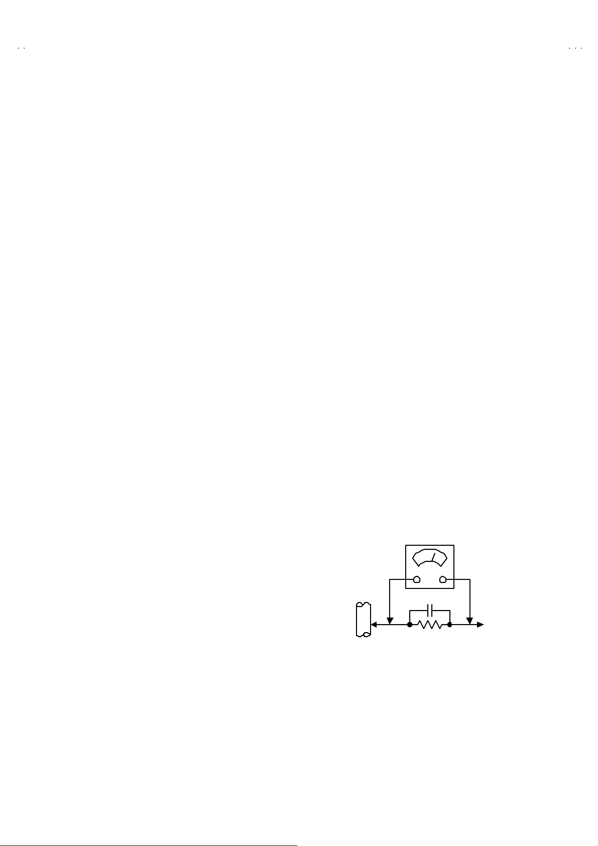
"""" Altern at e Che ck M ethod
Plug th e AC l in e c ord d ir ect ly into the A C ou tlet (d o n ot use a lin e
isol ati o n transformer during t hi s che ck.) . Use an AC vo lt meter
h avi ng 1 000 oh ms pe r volt or m or e sens it i vity i n th e fo llowi ng
mann er . C on nec t a 1 500Ω 10W res ist or par a lle le d b y a 0 .15µF
AC-type c apa cit or bet ween an ex po sed met al pa rt a nd a kno wn
g ood e ar th gro un d ( wa ter pi pe , etc.) . M eas ur e th e AC vo lt ag e
acr oss th e r es ist or wi th th e AC vo ltmeter . Move th e resi stor
con nec tion to e ach ex p os e d me tal par t, p art icul ar ly any exp osed
metal p ar t hav in g a r etu rn pat h to t he ch assi s, an d m easu r e th e
AC vol tag e ac ro s s the r es ist or. No w , re verse th e plu g in th e AC
ou tl et and re pe at eac h mea suremen t. An y vol t ag e measu red
must no t e xceed 0 .7 5V AC (r.m.s.). This c orresponds to 0.5mA
AC (r.m.s.).
Howeve r, in tropica l area, this must n ot exceed 0.3V AC ( r.m. s.) .
This corresponds to 0.2mA AC (r.m.s.).
AC VOLT METER
(HAVING 1000 Ω /V,
OR MOR E SENSIT IVITY)
0.15μF AC-T YPE
PLACE THIS PROBE
1500 Ω 10W
GOOD EARTH GROUND
ON E A C H EX PO SE D
ME T AL PA RT
No.52023
3
A
V-21DMT3/AV-21D3
A
A
V-2135TEE/AV-2135EE
V-21DMG3
FEATURES
"
New c h assi s d esign enabl es us e of an int eractive on-scr ee n c ont ro l.
"
Wide ran ge volt age ( 1 10V~240V) AC power input.
" With AUDIO / VI DEO INPUT & OUTPUT te rminal.
"
MUT IN G button can r ed uce th e audi o level to z er o i nst ant l y.
" Func t ion al r em ote contr ol t o oper a te T V set (f or chann el se lect, volum e con tr ol , p ower ON /OFF , etc. ) f rom a d ist anc e.
"
I2C bu s con tr ol ut ilizes single chi p ICs for IF, V /C, DEF. V SM PRES ET, PRESET & TURBO TIMER.
" By m eans of AUTO PR OGRA M, th e TV s tatio ns c an b e s electe d automatica lly a nd th e TV chann el s c an al so b e r ear r an ged a utom atically.
" The TEL ETEXT SYST EM ha s a built-i n FLOP s yst em . ( Only f or AV - 21DMT 3 / AV- 21 35 TEE)
"
Built- in ECO MODE (ECONOMY, ECOLOGY)
In acco rdanc e with th e br ig ht ness in a r oo m, th e br ig ht ness and / of c on tr as t of th e pictur e can b e a djust ed au tomat ic all y to m ak e th e
op ti mu m pictu re whic h is eas y on th e eye.
" Built – in ON TIMER, RETURN + & CHILD LOCK.
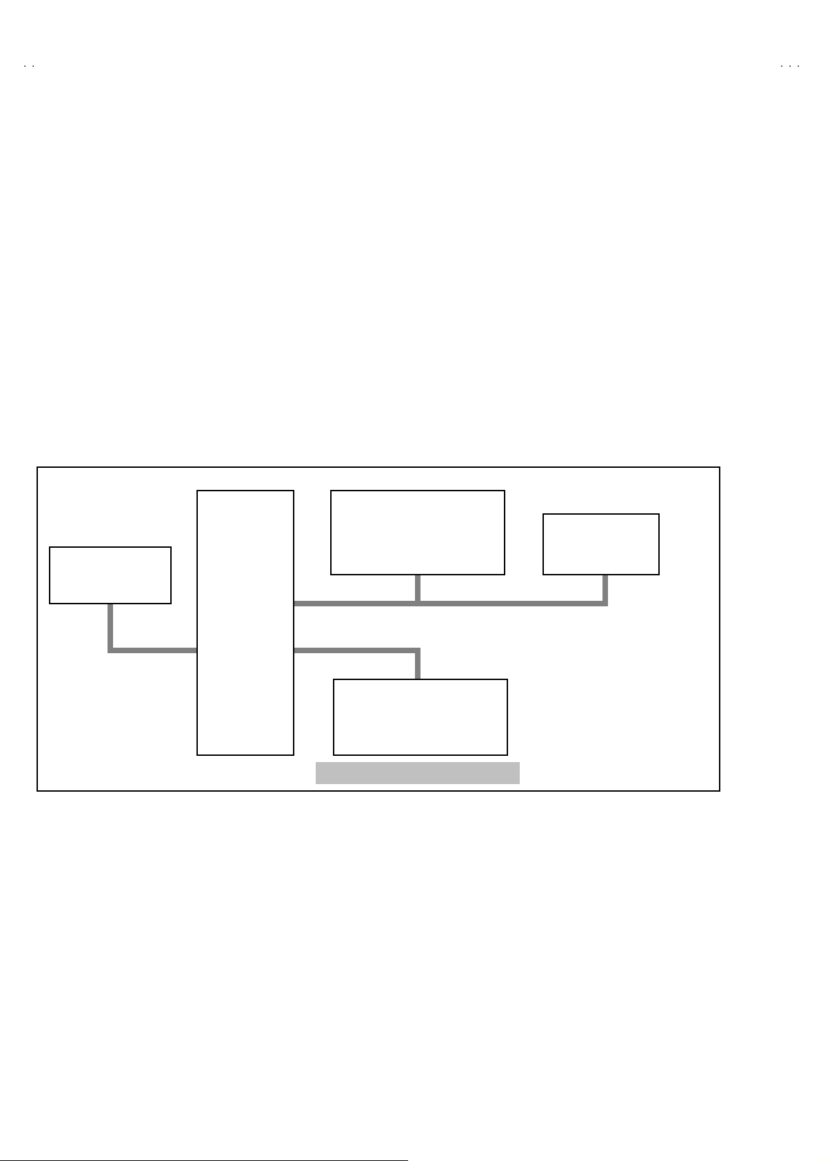
SYSTEM BLOCK DIAGRAM
"
IC702
MEMORY
IC701
SCL2/SDA2 TCL/TDA
MICRO
COMPUTER
IC301
VIDEO/CHROMA
DECORDER
SCL1/SDA1
IC821
TEXT DECORDER
Only f or AV -2 1DMT3 / AV- 21 35T EE
TU001
TUNER
4
No. 52023

A
3
A
A
FUNCTIONS
■
FRONT PANEL
10 9
1 2
3
4 5 6 7 8
MENU buttons
1
CHANNEL -/+ butto ns
2
VOLUME -/+ butto ns
3
AI ECO sen sor
4
REMO TE CONTR OL s ens or
5
ON TIMER lamp
6
POWER lamp
7
MAIN POWER button
8
A/V IN PUT t erminal
9
HEAD PHONE jack
10
V-21DMT3/AV-21D
V-2135TEE/AV-2135EE
V-21DMG3
■
REAR TERMINAL
1
ANT Terminal
1
2
3
4
5
VIDEO INPUT Term inal
2
VIDEO OUTPUT Terminal
3
AUDIO INPUT T ermin al
4
AUDIO OUT PUT Terminal
5
No. 52023
5
A
V-21DMT3/AV-21D3
A
A
V-2135TEE/AV-2135EE
V-21DMG3
■
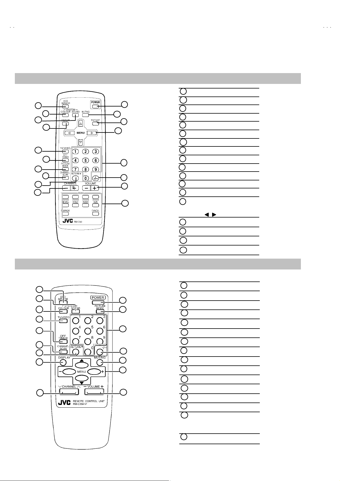
REMOTE CO NT ROL UNIT
RM-C90 : (AV-21DMT3 / AV-2135TEE)
1
2
3
4
5
6
7
8
9
10
11
12
13
14
15
16
17
18
ECO S ENSOR ke y
1
COLOUR SY STEM ke y
2
SOUND SYSTEM key
3
DISPLAY key
4
TV/VI DEO key
5
OFF TIMER key
6
PICTURE MODE key
7
CHANNEL SC AN key
8
RETURN+key
9
CHANNEL -/+ key
10
POWER key
11
MUTING key
12
TV/TEXT key
13
MENU ke y
14
MENU ▲/▼ key
MENU / key
Number (CH.) key
15
-/--key
16
VOL UME -/+ key
17
Teletext key
18
RM-C364GY : (AV-21D3/D / AV-21 35EE / AV-21DMG3 / AV-21DMG3
ECO S ENSOR ke y
1
2
3
4
5
6
7
8
9
10
11
12
13
14
15
16
1
SOUND SYSTEM key
2
COLOUR SY STEM ke y
3
4
TV/V IDEO key
OFF TIMER key
5
CHA NNEL SC AN k ey
6
RETURN+key
7
DISPLAY key
8
CHANNEL key
9
POWER key
10
PICTURE MODE key
11
Number (CH.) key
12
-/ --key
13
MUTING key
14
MENU ke y
15
MENU ▲/▼ key
MENU -/+ key
VOL UME-/+ key
16
/-A
)
6
No. 52023
A
3
A
A
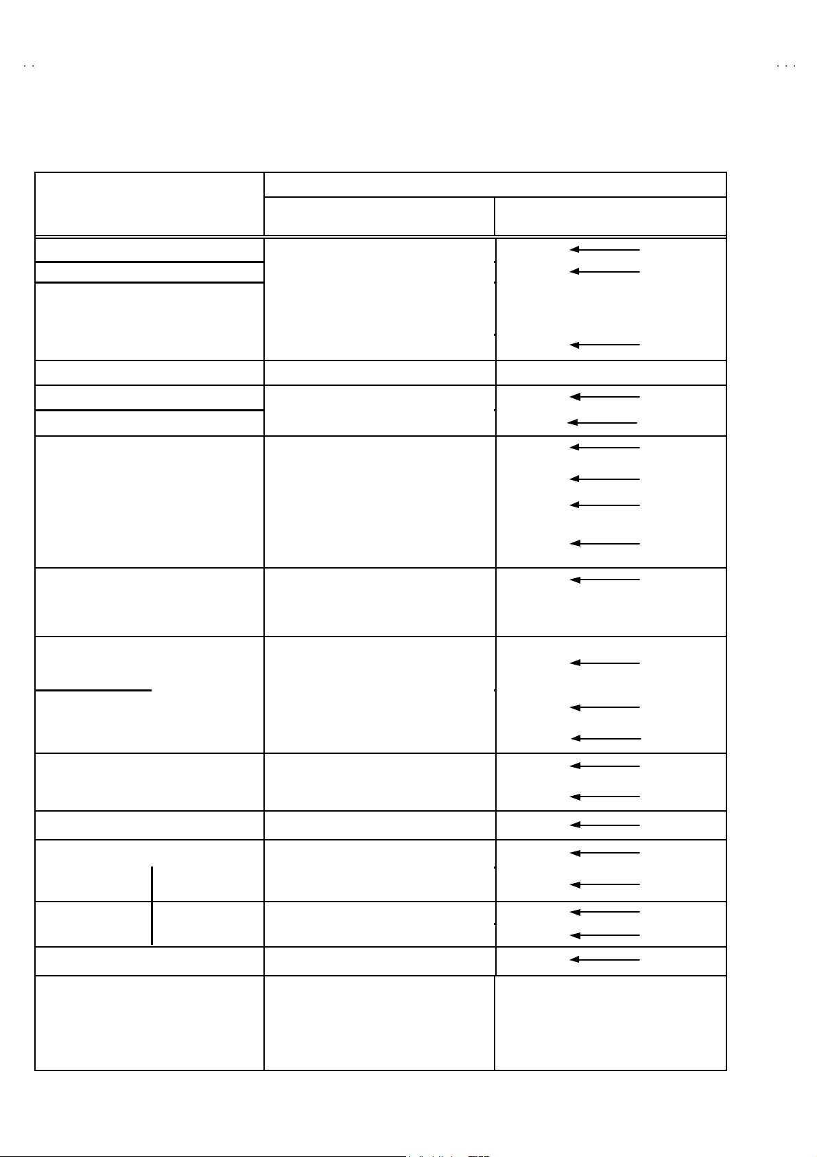
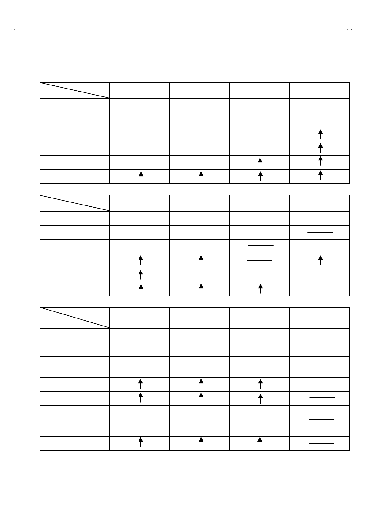
MAIN DIFFERENCE LIST
V-21DMT3/AV-21D
V-2135TEE/AV-2135EE
V-21DMG3
Part Name
Model Name
AV-21DMT 3 SCG-1315A-H2 LC11129-017A-H RM-C90-H
AV-21D3
/D
AV-2135TEE SCG-1407A-H2
AV-2135EE SCG-1406A-H2
AV-21DMG3 SCG-1409A-H2
AV-21DMG3
/-A
Part Name
Model Name
AV-21DMT 3
AV-21D3
/D
Main PWB Front Cabinet Remote Control Unit Rating Label
GG20025-001A-H
SCG-1408A-H2 LC11129-018A-H RM-C364GY-H
GG20024-001A-H
LC11129-015A-H RM-C90-H
LC11129-016A-H RM-C364GY-H
LC11129-017A-H
Picture Tube Inst Book Digest Manual Warranty Card
A51LQC095X LCT1174- 001A-H LCT1175-001A-H
A51LMV10X LCT1188- 001A-H LCT1190-001A-H
AV-2135TEE A51LQC095X LCT1195-001A- H BT-54012-2
AV-2135EE
AV-21DMG3
AV-21DMG3
Item
Model Name
/-A
TV RF Syst e m
LCT1196- 001A-H LCT1197-001A-H
Co l our S yst em
[ RF Mode ]
Interm ediate
Frequency
[ SIF Carrier ]
Teletext System
32.5MHz (5.5MHz)
AV-21DMT 3 B/G,I,D/K,&M
AV-21D3
/D
B/G,I,D/K
PA L / SE CAM
NTSC 3.5 8 / NTS C4.4 3
PA L / SE CAM
33.5MHz (4.5MHz)
31.5MHz (6.5MHz)
32.0MHz
(6.0MHz)
32.5MHz (5.5MHz)
31.5MHz (6.5MHz)
32.0MHz
(6.0MHz)
FLOP
AV-2135TEE FLOP
AV-2135EE
32.5MHz (5.5MHz)
AV-21DMG3
B/G,I,D/K,&M
PA L / SE CAM
NTSC 3.5 8 / NTS C4.4 3
33.5MHz (4.5MHz)
31.5MHz (6.5MHz)
32.0MHz (6.0MHz)
AV-21DMG3
/-A
No. 52023
7

A
V-21DMT3/AV-21D3
A
A
V-2135TEE/AV-2135EE
V-21DMG3
SPECIFIC SERVICE INSTRUCTIONS
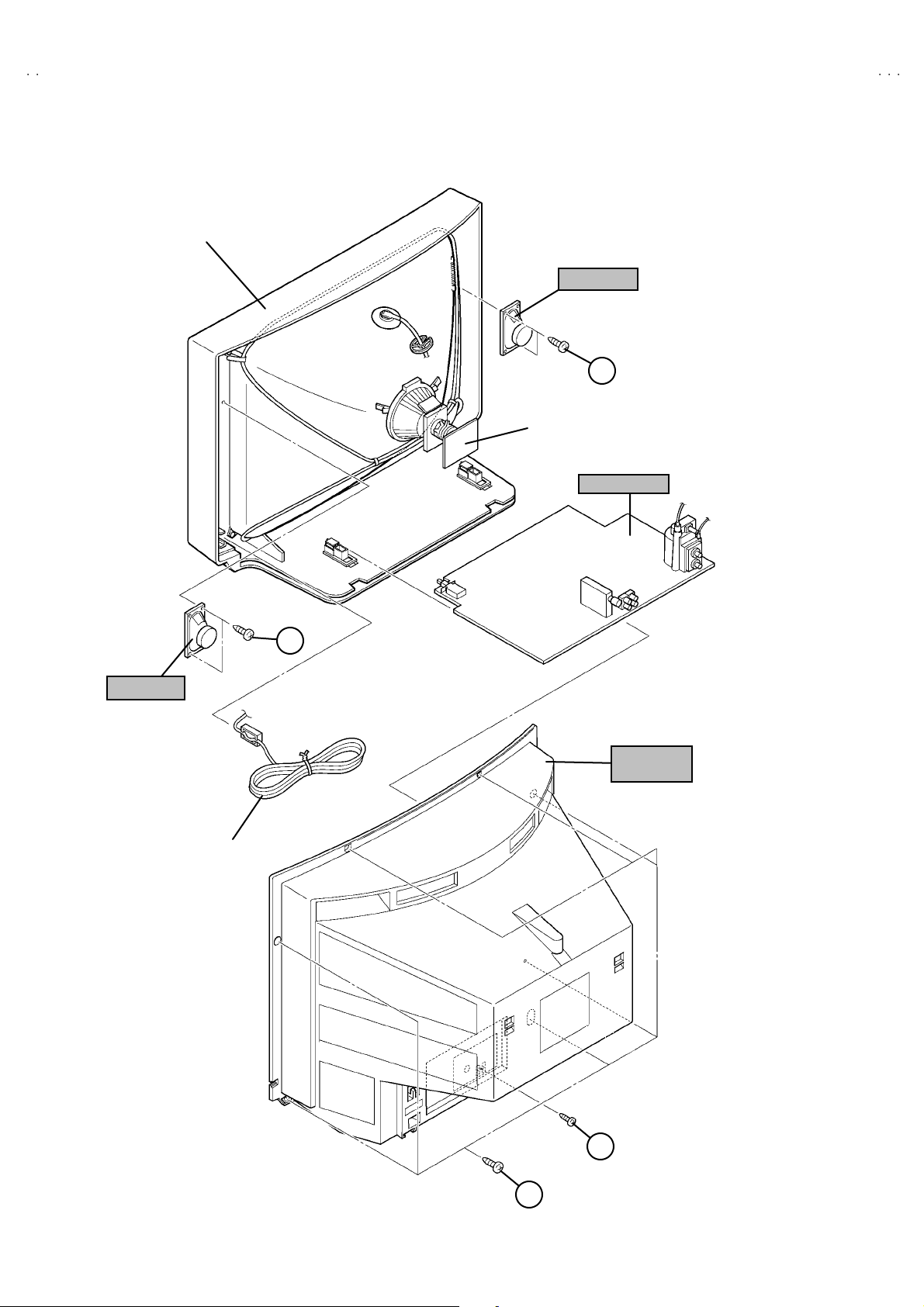
DISASSEMBLY PROCEDURE
REMOVING THE REAR COVER
1. Unp lug t he po wer plu g.
####
!!!!
.
an d a
2. As sh own in f igure , r em ov e t he 7 screws marked
screw marked "
3. W i thdr a w t he r ear co ver to wa rd you .
".
""
REMOVING THE MAIN PW BOARD
" After removing the rear cover.
1. Sl ight l y raise t he bo th sid es of t he M AIN PW BOARD by hand .
2. W i thdr a w t he M AIN PW B OARD b ackw ar d.
(If necess ar y, ta ke off the w ire c lamp, conn ect or s etc. )
REMOVING THE SPEAKER
"
After removing the rear cover.
1. As sh own in fi gu r e, remove the 2 screws ma rked
2. Foll ow th e s ame st eps when r em oving the oth er ha nd speak er.
CHECKIN G THE MAIN PW BOARD
1. To ch eck the ba ck side of the PW B oar d.
1) Pu ll out the MA IN PW Bo ard. ( Ref er to RE MO VING TH E MAIN
PW B oar d)
2) Erect th e PW Board vert ic al ly so th at y ou can easi l y ch eck th e
b ack side of th e PW Boar d.
[CAUTION]
" When e re c ti ng the PW Board, be c ar ef ul s o that th ere w ill b e n o
con tact in g with ot her PW Boar d.
" Before turning on power, make sure that the CRT earth wire and
oth er co nne cto r ar e p rope rly c onn ect ed.
WIRE CLAMPIN G AND CABLE TYING
1. Be sure t o clamp th e wire.
2. N ever rem o ve th e c able tie use d f or tyi ng the wire s to ge the r.
Sh oul d i t be inad verte ntly r em ove d, be su re to tie th e w ires w it h a
new cable tie.
8
No. 52023
A
3
A
A
FRONT CABI.
V-21DMT3/AV-21D
V-2135TEE/AV-2135EE
V-21DMG3
SP EAKER
C
CRT SOCKET
PWB
MAIN PWB
SP EAKER
C
REAR
COVER
POWER
CORD
B
A
No. 52023
9
A
V-21DMT3/AV-21D3
A
A
S
U
/C
NUMBERS
GU
O
/
3
V-2135TEE/AV-2135EE
V-21DMG3
REPLACEMENT OF MEMORY ICs
1. MEMORY ICs
Thi s mod el u ses me mo r y I Cs. This memo r y IC da ta are f or pr o per opera tion of th e vide o a nd defl ect io n cir cuits.
When r ep la cing memory ICs , b e su r e to use ICs w r it ten w i th t he ini tial v a lu es of dat a.
2. PROCEDURE FOR REPLACIN G MEMORY ICs
(1) Power off
Switch the p ower of f and di sc o nn ect t he pow e r plu g f rom t he w al l out let.
(2) Replace ICs
Be sure to use memory ICs written with the initial data values.
(3) Power on
Connect th e pow er plu g i nt o the wal l ou tl et and s w itch t he po we r on .
(4) C heck and s et SY STEM CONSTAN T SET
・・・・ It must not adjust without adjustment signals.
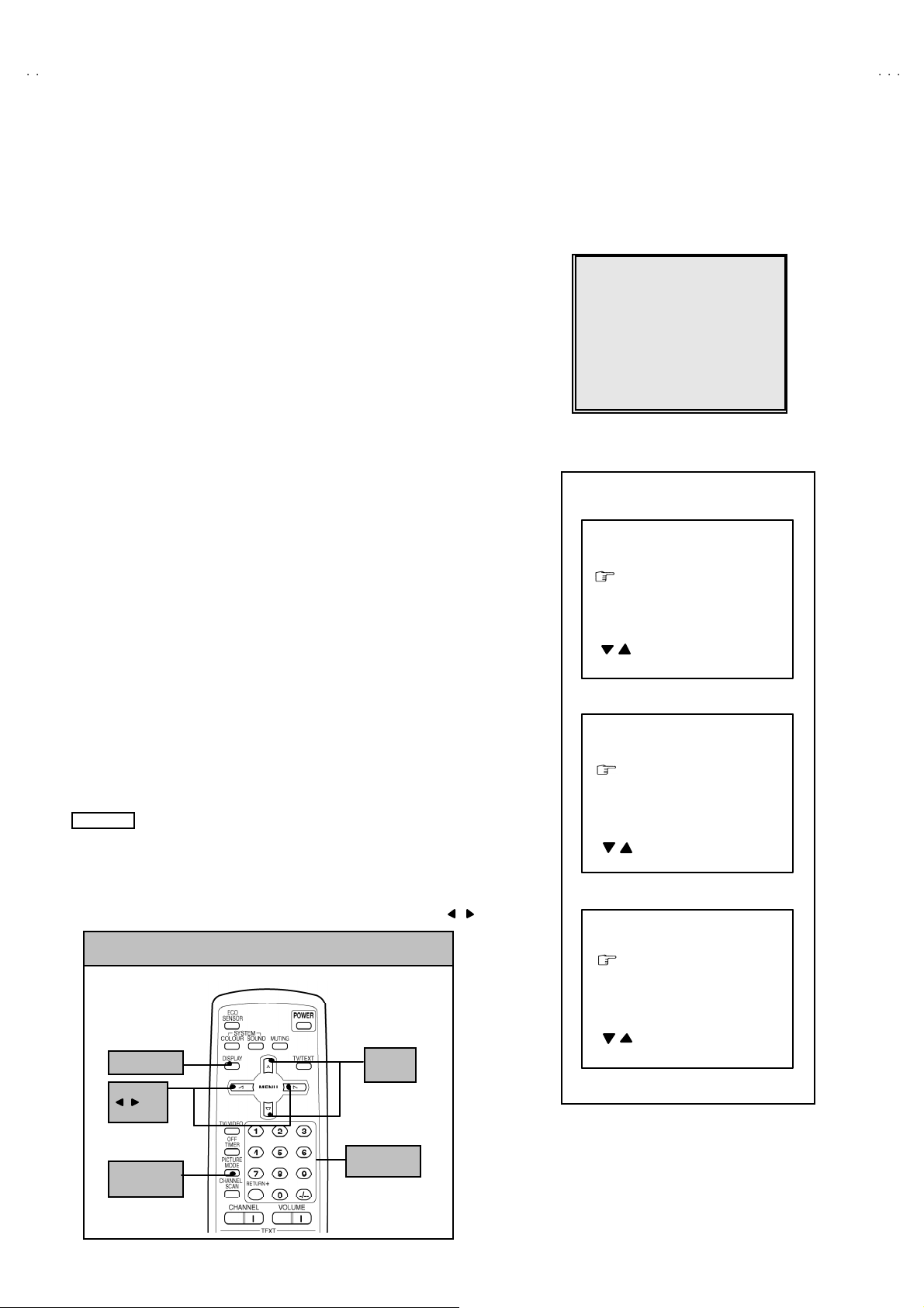
1) Press th e DI SPLAY key and the PICTURE MODE key of the REMOTE
CONTROL UNIT simultaneously.
2) The SERVICE MENU screen of Fig. 1 will be displayed.
3) W hi l e th e SE RV IC E M EN U is di splayed , ag ain press the DI SPLAY ke y and
PICTURE MODE ke y s imulta neo us l y, an d t he S YSTEM C ONSTA NT SE T
screen of Fig. 2 w ill b e di splayed.
1) Check the s ettin g val ue s of the S YST E M CO N ST AN T S ET of T abl e 1 If th e
val u e is diffe re nt, select the sett ing item with the MENU ▼/▲key, and set
th e co rrect valu e with t he MENU - / + k ey.
5) Press the DI SPLAY ke y twic e, and r eturn t o the n orm al scr ee n.
(5) Receive channel of setting
Refe r to th e OPE RATING INST RUCTIONS and set th e rec e i ve cha nn els
(chan nels prese t) as descr i be d
(6) User Setting
Check t he us er s etti n g v al u e of T ab l e 2, and if setti ng v alue is di f feren t, set
th e co rrect valu e.
For setting , refer to the OPE RATING INSTRUCTIO NS.
(7) Setting of SERVICE MENU
Ve rif y the s et ting it ems of th e SER VICE MENU, and r eset whe r e n ecess a r y.
For setting , refer to the SERVICE ADJUSTMENTS.
NOTE
Alth ou gh th e k ey p osi tion of t he RM-C90 r e mote control unit is diff erent fr o m
th at of th e RM -C36 4GY rem ot e cont rol un it , th e f unctio ns of both u ni ts a re the
sam e So pl e as e use th e attac hed d i agr am for the RM-C90 remote control
uni t fo r the R M-C36 4GY.
By t he way, MENU -/+ Key fu nction s in t he sam e ma nner as for / key.
KEY ASSIGNMENT OF REMOTE CONTROL UNIT
ERVICE MEN
1.IF 2.V
3.DEF 4.VSM PRESET
5.PRES ET
6. TURB O T I MER O F F
1-6 SELECT DISP : EXIT
******
***********
***** **
************
**********
*** ** **
*** ** **** ***
*** ** ***** ** **
**.***
****
** ***
** ***** ***
***
******
Fig.1
SY STEM C ON STA NT- ⅠⅠⅠⅠ
SYSTEM CONSTA NT SE T 1
COL O UR :
BI LIN
AL : N
TUNE R : MU
ECO SENSOR : YES
LANG U AG E :
: SELECT
- / + : OPERATE DISP : EX IT
***
***
SY STEM C ON STA NT- ⅡⅡⅡⅡ
SYSTEM CONSTA NT SE T 2
B/B SO UND : O FF
LOCK : 180
COL OUR AU TO :
QSS : MINT
ALC : NO
TEXT R ATE : 2 0
: SELECT
/
- / + : OPERATE DISP : EX IT
***
SY STEM C ON STA NT-
SYSTEM CONSTANT SET
AMP TUNER : NO
VNR : YES
TEXT TABLE :
VOLUM PWM : POS
***
ⅢⅢⅢⅢ
10
DI SPL A Y k ey
MENU
/ key
PICTURE
MO DE k e y
MENU
▼/▲
key
(RM-C90)
key
No. 52023
: SELECT
/
- / + : OPERATE DISP : EX IT
Fig.2
Loading...