


AV-20F704
Table of contents
 Loading...
SERVICE MANUAL
COLOR TELEVISION
AV-20F704
AV-20F704
3
3
2
2
1
1
4
4
6
6
5
5
7
7
9
9
8
8
0
0
CH
CH
VOL
VOL
VOL
VOL
CH
CH
CONTENTS
q SPECIFICATIONS.............................................................................................................................................. 2
q OPERATING INSTRUCTIONS (APPENDIX)
q SAFETY PRECAUTIONS .................................................................................................................................. 3
q SPECIFIC SERVICE INSTRUCTIONS .............................................................................................................. 4
q SERVICE ADJUSTMENTS ................................................................................................................................ 8
q GUIDE FOR REPAIRING ................................................................................................................................. 13
q STANDARD CIRCUIT DIAGRAM ................................................................................................................... 2-1
q PARTS LIST ..................................................................................................................................................... 21
COPYRIGHT © 2003 VICTOR COMPANY OF JAPAN, LTD.
No. 52131
2003/05

AV-20F704
SPECIFICATIONS
TELEVISION
Picture Tube: 20” (measured diagonally)
Color System: NTSC
TV RF System: US System M
Tuner Type: 181 Channel, Quartz PLL Frequency Synthesized
Receiving Channels: VHF 2-13
UHF 14-69
CATV 01-97 (5A)-(A-3)
98-99 (A-2)-(A-1)
14-22 (A)-(I)
23-36 (J)-(W)
37-65 (AA)-(FFF)
66-125 (GGG)-(125)
Intermediate Frequency: Picture (FP) : 45.75 MHz
Sound (FS) : 41.25 MHz
FP-FS : 4.50 MHz
Antenna Input: VHF/UHF/CATV In 75 ohms coaxial, F-Type Connector
Speaker: 2” x 4-3/4”, 8 ohms x 2
Audio Output Power: 2.5 W + 2.5 W
GENERAL
Power Source: 120 V AC, 60 Hz
Power Consumption: 105 Watts
Dimensions(W x H x D): 23-1/4” (590 mm) x 17-1/2” (444 mm) x 19-3/4” (498.5 mm)
Weight: 55.2 Ibs/25 kg
Video/Audio Inputs: Component input
Y input: 1.0 Vp-p, 75 ohm (RCA pin jack)
Pb, Pr input : 0.7 Vp-p, 75 ohm (RCA pin jack)
S-Video input
Y input: 1.0 Vp-p, 75 ohm
C input: 0.3 Vp-p, 75 ohm
Video input: 1.0 Vp-p, 75 ohm (RCA pin jack)
Audio input: -8dB, 47 kohm (RCA pin jack)
Headphone Jack: 3.5 mm mini-jack
Storage Temperature -20 °C ~ 60 °C
Operating Temperature 5 °C ~ 40 °C
Accessories:
Remote Control X 1
Batteries (UM-3) X 2
Design & specification are subject to change without notice.
2
No. 52131
SAFETY PRECAUTIONS
SERVICING NOTICES ON CHECKING
AV-20F704
1. KEEP THE NOTICES
As for the places which need special attentions, they are
indicated with the labels or seals on the cabinet, chassis and
parts. Make sure to keep the indications and notices in the
operation manual.
2. AVOID AN ELECTRIC SHOCK
There is a high voltage part inside. Avoid an electric shock
while the electric current is flowing.
3. USE THE DESIGNATED PARTS
The parts in this equipment have the specific characters of
incombustibility and withstand voltage for safety. Therefore,
the part which is replaced should be used the part which has
the same character.
Especially as to the important parts for safety which is
indicated in the circuit diagram or the table of parts as a !
mark, the designated parts must be used.
4. PUT PARTS AND WIRES IN THE ORIGINAL
POSITION AFTER ASSEMBLING OR WIRING
There are parts which use the insulation material such as a
tube or tape for safety, or which are assembled in the condition
that these do not contact with the printed board. The inside
wiring is designed not to get closer to the pyrogenic parts and
high voltage parts.
Therefore, put these parts in the original positions.
5. TAKE CARE TO DEAL WITH THE
CATHODE-RAY TUBE
In the condition that an explosion-proof cathoderay tube is set
in this equipment, safety is secured against implosion.
However, when removing it or serving from backward, it is
dangerous to give a shock. Take enough care to deal with it.
6. AVOID AN X-RAY
Safety is secured against an X-ray by considering about the
cathode-ray tube and the high voltage peripheral circuit, etc.
Therefore, when repairing the high voltage peripheral circuit,
use the designated parts and make sure not modify the
circuit.
Repairing except indicates causes rising of high voltage, and
it emits an X-ray from the cathoderay tube.
7. PERFORM A SAFETY CHECK AFTER SERVICING
Confirm that the screws, parts and wiring which were
removed in order to service are put in the original positions, or
whether there are the portions which are deteriorated around
the serviced places serviced or not. Check the insulation
between the antenna terminal or external metal and the AC
cord plug blades. And be sure the safety of that.
(INSULATION CHECK PROCEDURE)
1. Unplug the plug from the AC outlet.
2. Remove the antenna terminal on TV and turn on the TV.
3. Insulation resistance between the cord plug terminals and
the eternal exposure metal [Note 2] should be more than
1M ohm by using the 500V insulation resistance meter
[Note 1].
4. If the insulation resistance is less than 1M ohm, the
inspection repair should be required.
[Note 1]
If you have not the 500V insulation resistance meter, use a
Tester.
[Note 2]
External exposure metal:Antenna terminal
Earphone jack
HOW TO ORDER PARTS
Please include the following informations when you order parts. (Particularly the VERSION LETTER.)
1. MODEL NUMBER and VERSION LETTER
The MODEL NUMBER can be found on the back of each product and the VERSION LETTER can be found at the end of the SERIAL
NUMBER.
2. PART NO. and DESCRIPTION
You can find it in your SERVICE MANUAL.
IMPORTANT
Inferior silicon grease can damage IC's and transistors.
When replacing an IC's or transistors, use only specified silicon grease (YG6260M).
Remove all old silicon before applying new silicon.
No. 52131
3
AV-20F704
SPECIFIC SERVICE INSTRUCTIONS
DISASSEMBLY INSTRUCTIONS
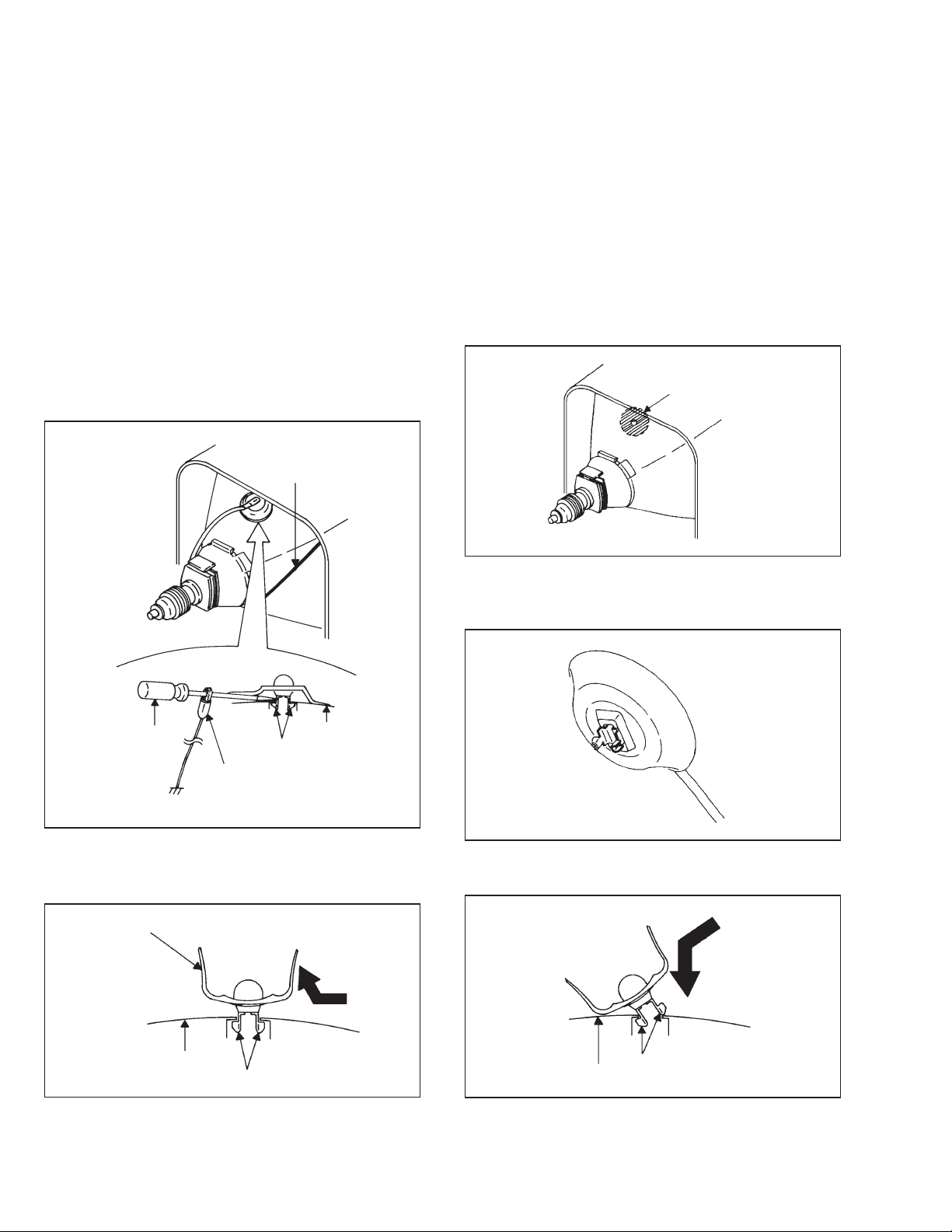
1. REMOVAL OF ANODE CAP
Read the following NOTED items before starting work.
* After turning the power off there might still be a potential voltage
that is very dangerous. When removing the Anode Cap, make
sure to discharge the Anode Cap's potential voltage.
* Do not use pliers to loosen or tighten the Anode Cap terminal,
this may cause the spring to be damaged.
REMOVAL
1. Follow the steps as follows to discharge the Anode Cap.
(Refer to Fig. 1-1.)
Connect one end of an Alligator Clip to the metal part of a flatblade screwdriver and the other end to ground.
While holding the plastic part of the insulated Screwdriver, touch
the support of the Anode with the tip of the Screwdriver.
A cracking noise will be heard as the voltage is discharged.
GND on the CRT
3. After one side is removed, pull in the opposite direction to
remove the other.
NOTE
Take care not to damage the Rubber Cap.
INSTALLATION
1. Clean the spot where the cap was located with a small amount of
alcohol. (Refer to Fig. 1-3.)
NOTE
Confirm that there is no dirt, dust, etc. at the spot where the cap
was located.
Location of Anode Cap
Fig. 1-3
2. Arrange the wire of the Anode Cap and make sure the wire is not
twisted.
3. Turn over the Rubber Cap. (Refer to Fig. 1-4.)
Screwdriver
Support
CRT
Alligator Clip
GND on the CRT
2. Flip up the sides of the Rubber Cap in the direction of the arrow
and remove one side of the support.
(Refer to Fig. 1-2.)
Fig. 1-1
Rubber Cap
CRT
Support
Fig. 1-2
Fig. 1-4
4. Insert one end of the Anode Support into the anode button, then
the other as shown in Fig. 1-5.
Support
CRT
5. Confirm that the Support is securely connected.
6. Put on the Rubber Cap without moving any parts.
Fig. 1-5
4
No. 52131
AV-20F704
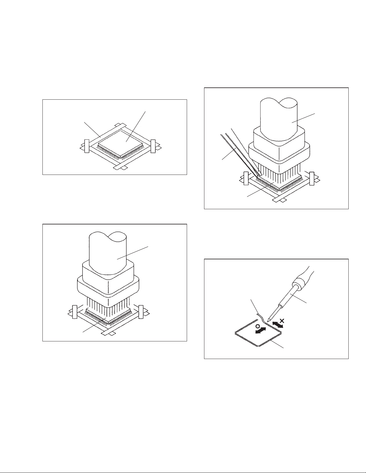
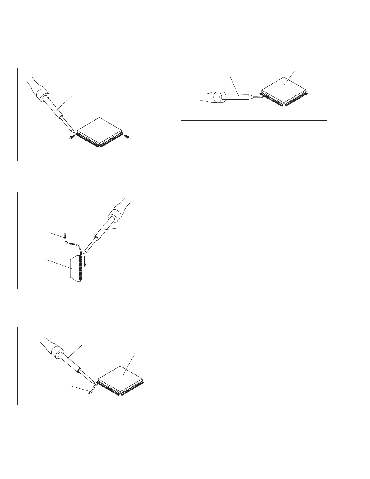
2. REMOVAL AND INSTALLATION OF
FLAT PACKAGE IC
REMOVAL
1. Put the Masking Tape (cotton tape) around the Flat Package IC
to protect other parts from any damage.
(Refer to Fig. 2-1.)
NOTE
Masking is carried out on all the parts located within 10 mm
distance from IC leads.
Masking Tape
(Cotton Tape)
2. Heat the IC leads using a blower type IC desoldering machine.
(Refer to Fig. 2-2.)
NOTE
Do not add the rotating and the back and forth directions force
on the IC, until IC can move back and forth
easily after desoldering the IC leads completely.
IC
Fig. 2-1
Fig. 2-1
Blower type IC
desoldering machine
3. When IC starts moving back and forth easily after desoldering
completely, pickup the corner of the IC using a tweezers and
remove the IC by moving with the IC desoldering machine.
(Refer to Fig. 2-3.)
NOTE
Some ICs on the PCB are affixed with glue, so be careful not
to break or damage the foil of each IC leads or solder lands
under the IC when removing it.
Blower type IC
desoldering machine
Tweezers
IC
Fig. 2-3
4. Peel off the Masking Tape.
5. Absorb the solder left on the pattern using the Braided Shield
Wire. (Refer to Fig. 2-4.)
NOTE
Do not move the Braided Shield Wire in the vertical direction
towards the IC pattern.
Braided Shield Wire
Soldering Iron
IC
Fig. 2-2
No. 52131
IC pattern
Fig. 2-4
5
AV-20F704
INSTALLATION
1. Take care of the polarity of new IC and then install the new IC
fitting on the printed circuit pattern. Then solder each lead on the
diagonal positions of IC temporarily.
(Refer to Fig. 2-5.)
Soldering Iron
Solder temporarily
Solder temporarily
Fig. 2-5
2. Supply the solder from the upper position of IC leads sliding to
the lower position of the IC leads.
(Refer to Fig. 2-6.)
4. When bridge-soldering between terminals and/or the soldering
amount are not enough, resolder using a Thintip Soldering Iron.
(Refer to Fig. 2-8.)
IC
Thin-tip Soldering Iron
Fig. 2-8
5. Finally, confirm the soldering status on four sides of the IC using
a magnifying glass.
Confirm that no abnormality is found on the soldering position
and installation position of the parts around the IC. If some
abnormality is found, correct by resoldering.
NOTE
When the IC leads are bent during soldering and/or repairing,
do not repair the bending of leads. If the bending of leads are
repaired, the pattern may be damaged. So, be always sure to
replace the IC in this case.
Solder
IC
Supply soldering
from upper position
to lower position
Soldering Iron
Fig. 2-6
3. Absorb the solder left on the lead using the Braided Shield Wire.
(Refer to Fig. 2-7.)
NOTE
Do not absorb the solder to excess.
Soldering Iron
IC
Braided Shield Wire
Fig. 2-7
6
No. 52131
SERVICE MODE LIST
This unit provided with the following SERVICE MODES so you can repair, examine and adjust easily.
To enter the Service Mode, press both set key and remote control key for more than 1 second.
Set Key Remocon Key Operations
VOL. (-) MIN
VOL. (-) MIN
VOL. (-) MIN
VOL. (-) MIN
VOL. (-) MIN
VOL. (-) MIN
0
1
3
6
8
9
Releasing of V-CHIP PASSWORD.
Initialization of the factory.
NOTE: Do not use this for the normal servicing.
If you set a factory initialization, the memories are reset such as the channel setting, and
the POWER ON total hours.
Remocon format selection. (JVC format → NEC format)
NOTE: Supplied remocon can not be operated at NEC format.
(The “N” is always displayed on the monitor.)
Do not use this for the normal servicing.
POWER ON total hours is displayed on the screen.
Refer to the “CONFIRMATION OF HOURS USED”.
Can be checked of the INITIAL DATA of MEMORY IC.
Refer to the “WHEN REPLACING EEPROM (MEMORY) IC”.
Writing of EEPROM initial data.
NOTE: Do not use this for the normal servicing.
Display of the Adjustment MENU on the screen.
Refer to the “ELECTRICAL ADJUSTMENT” (On-Screen Display Adjustment).
AV-20F704
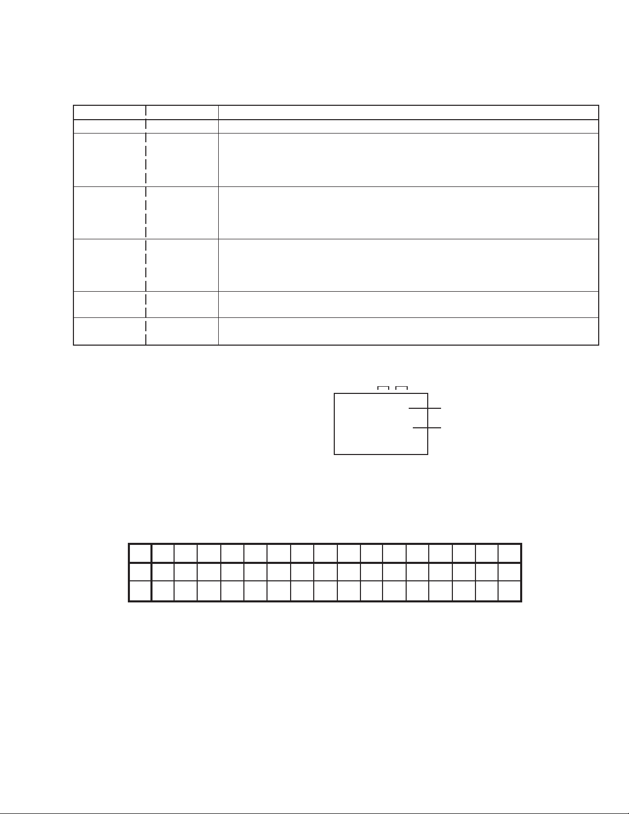
CONFIRMATION OF HOURS USED
POWER ON total hours can be checked on the screen.
Total hours are displayed in 16 system of notation.
NOTE:If you set a factory initialization, the total hours is reset
to “0”.
1. Set the VOLUME to minimum.
2. Press both VOL. DOWN button on the set and Channel button
(6) on the remote control for more than 1 second.
3. After the confirmation of using hours, turn off the power.
ADDRESS DATA
INIT 00 A9
CRT ON 0010
FIG. 1
Initial setting content of MEMORY IC.
POWER ON total hours.
= (16 x 16 x 16 x thousands digit value)
+ (16 x 16 x hundreds digit value)
+ (16 x tens digit value)
+ (ones digit value)
WHEN REPLACING EEPROM (MEMORY) IC
If a service repair is undertaken where it has been required to change the MEMORY IC, the following steps should be taken to
ensure correct data settings while making reference to TABLE 1.
NOTE: No need setting for after INI 10 due to the adjustment value.
INI
+0 +1 +2 +3 +4 +5 +6 +7 +8 +9 +A +B +C +D +E +F
A9 C3 02 00 31 B3 AF 37 BF 0A
00 44 04 00 00 00 70
40 00 00 00 00 00 00 00 0010 00 00 00 0F A5 45 20
Table 1
1. Enter DATA SET mode by setting VOLUME to minimum.
2. Press both VOL. DOWN button on the set and Channel button (6) on the remote control for more than 1 second.
ADDRESS and DATA should appear as FIG 1.
3. ADDRESS is now selected and should “blink”. Using the VOL. +/- button on the remote, step through the ADDRESS until required
ADDRESS to be changed is reached.
4. Press ENTER to select DATA. When DATA is selected, it will “blink”.
5. Again, step through the DATA using VOL. +/- button until required DATA value has been selected.
6. Pressing ENTER will take you back to ADDRESS for further selection if necessary.
7. Repeat steps 3 to 6 until all data has been checked.
8. When satisfied correct DATA has been entered, turn POWER off (return to STANDBY MODE) to finish DATA input.
After the data input, set to the initializing of shipping.
9. Turn on the POWER.
10. Press both VOL. DOWN button on the set and Channel button (1) on the remote control for more than 1 second.
11.After the finishing of the initializing of shipping, the unit will turn off automatically.
The unit will now have the correct DATA for the new MEMORY IC.
No. 52131
7
Loading...