


EFG 213-320 |
06.08- |
|
|
|
|
|
|
|
G
Operating Instructions
51099986
07.11

Declaration of Conformity
Jungheinrich AG, Am Stadtrand 35, D-22047 Hamburg
Manufacturer or his authorized representative in the Community
Type |
Option |
Serial No. |
Year of construc- |
|
|
|
tion |
EFG 213
EFG 215
EFG 216k
EFG 216
EFG 218k
EFG 218
EFG 220
EFG 316k
EFG316
EFG318k
EFG 318
EFG 320
Additional information
Authorised signatory
Date
GEU Declaration of Conformity
The signatories hereby certify that the specified powered industrial truck conforms to the EU Directive 2006/42/EC (Machine Directive) and 2004/108/EEC (Electro-Mag- netic Compatibility, EMC) including their amendments as translated into national legislation of the member countries. The signatories are individually empowered in each case to compile the technical documentation.
09.09 EN
3
4
09.09 EN
Foreword
The present ORIGINAL OPERATING INSTRUCTIONS are designed to provide sufficient instruction for the safe operation of the industrial truck. The information is provided clearly and concisely. The chapters are arranged by letter. Each chapter starts with page 1. The page identification consists of a chapter letter and a page number.
For example: Page B 2 is the second page in chapter B.
The operating instructions detail different truck models. When operating and servicing the truck, make sure that the instructions apply to your truck model.
Safety instructions and important explanations are indicated by the following graphics:
FUsed before safety instructions which must be observed to avoid danger to personnel.
MUsed before notices which must be observed to avoid material damage.
ZUsed before notices and explanations.
tUsed to indicate standard equipment.
oUsed to indicate optional equipment.
Our trucks are subject to ongoing development. Jungheinrich reserves the right to alter the design, equipment and technical features of the truck. No guarantee of particular features of the truck should therefore be inferred from the present operating instructions.
Copyright
Copyright of these operating instructions remains with JUNGHEINRICH AG.
Jungheinrich Aktiengesellschaft
Am Stadtrand 35
22047 Hamburg - GERMANY Telephone: +49 (0) 40/6948-0 www.jungheinrich.com
0108.GB
0108.GB
Table of contents
A Correct Use and Application
BTruck Description
1 |
Application ........................................................................................... |
B 1 |
2 |
Assemblies and Functional Description .............................................. |
B 2 |
2.1 |
Truck ................................................................................................... |
B 3 |
3 |
Standard Version Specifications ......................................................... |
B 4 |
3.1 |
EFG 213-220 performance data ......................................................... |
B 4 |
3.2 |
EFG 316-320 performance data ......................................................... |
B 5 |
3.3 |
EFG 213-220 dimensions ................................................................... |
B 6 |
3.4 |
EFG 316-320 dimensions ................................................................... |
B 8 |
3.5 |
EFG 213-220 weights ......................................................................... |
B 10 |
3.6 |
EFG 316-320 weights ......................................................................... |
B 10 |
3.7 |
EFG 213-220 tyres .............................................................................. |
B 11 |
3.8 |
EFG 316-320 tyres .............................................................................. |
B 11 |
3.9 |
EFG 213-320 mast versions ............................................................... |
B 12 |
3.10 |
EN norms ............................................................................................ |
B 13 |
3.11 |
Conditions of use ................................................................................ |
B 13 |
4 |
Identification points and data plates .................................................... |
B 14 |
4.1 |
Truck data plate .................................................................................. |
B 16 |
4.2 |
Truck load chart .................................................................................. |
B 16 |
4.3 |
Fork load diagram (basic model) ......................................................... |
B 17 |
4.4 |
Attachment load chart ......................................................................... |
B 17 |
CTransport and Commissioning
1 |
Transport ............................................................................................. |
C 1 |
2 |
Lifting by crane .................................................................................... |
C 1 |
3 |
Securing the truck during transport ..................................................... |
C 2 |
4 |
Using the truck for the first time .......................................................... |
C 3 |
5 |
Operating the truck without its own drive system ................................ |
C 3 |
6 |
Moving the truck when the electric/hydraulic steering has failed ........ |
C 4 |
7 |
Towing the Truck ................................................................................. |
C 4 |
0608.GB
I 1
DBattery Maintenance, Charging & Replacement
1 |
Safety regulations for handling acid batteries ..................................... |
D 1 |
2 |
Battery types ....................................................................................... |
D 2 |
3 |
Battery removal and installation .......................................................... |
D 3 |
3.1 |
Removal and installation using a multi-adapter (o) ............................ |
D 3 |
3.2 |
Removal and installation using a worktable for crane loading (o) ...... |
D 5 |
3.3 |
Removal and installation using a fork shoe (o) .................................. |
D 6 |
3.4 |
Removal and assembly for maintenance ............................................ |
D 7 |
4 |
Charging the battery ............................................................................ |
D 8 |
4.1 |
Charging the battery with a stationary charger ................................... |
D 8 |
4.2 |
Charging the battery with an on-board charger ................................... |
D 9 |
EOperation
1 |
Safety Regulations for the Operation of Forklift Trucks ...................... |
E 1 |
2 |
Controls and Displays ......................................................................... |
E 2 |
2.1 |
SOLOPILOT / MULTIPILOT ................................................................ |
E 4 |
2.2 |
Armrest control panel switch (o) ........................................................ |
E 5 |
2.3 |
Side pocket control panel switch (o) .................................................. |
E 5 |
2.4 |
Dashboard control panel and driver’s display ..................................... |
E 6 |
2.5 |
Battery Discharge Indicator, Battery Discharge Monitor, Hourmeter .. |
E 11 |
3 |
Starting up the truck ............................................................................ |
E 12 |
3.1Checks and operations to be performed before starting daily
|
operation ............................................................................................. |
E 12 |
3.2 |
Adjusting the driver’s seat ................................................................... |
E 12 |
3.3 |
Safety restraint belt ............................................................................. |
E 14 |
3.4 |
Mechanical safety restraint system (o) .............................................. |
E 15 |
3.5 |
Adjusting the steering column ............................................................. |
E 16 |
3.6 |
To prepare the truck for operation ....................................................... |
E 16 |
4 |
Industrial Truck Operation ................................................................... |
E 17 |
4.1 |
Safety regulations for truck operation ................................................. |
E 17 |
4.2 |
Travel, steering, braking ...................................................................... |
E 19 |
4.3 |
Operating the lift mechanism and attachments (SOLOPILOT t) ....... |
E 22 |
4.4 |
Operating the lift mechanism and attachments (MULTIPILOT o) ...... |
E 24 |
4.5 |
Emergency lowering ............................................................................ |
E 26 |
4.6 |
Adjusting the forks ............................................................................... |
E 26 |
4.7 |
Collecting, Lifting and Transporting Loads. ......................................... |
E 27 |
4.8 |
Parking the truck safely ....................................................................... |
E 28 |
4.9 |
Towing trailers ..................................................................................... |
E 29 |
5 |
Troubleshooting .................................................................................. |
E 30 |
5.1 |
Temperature control ............................................................................ |
E 30 |
0608.GB
I 2
FIndustrial Truck Maintenance
1 |
Operational Safety and Environmental Protection ............................... |
F 1 |
2 |
Maintenance Safety Regulations ......................................................... |
F 1 |
3 |
Servicing and Inspection ...................................................................... |
F 3 |
4 |
Maintenance checklist .......................................................................... |
F 4 |
5 |
Lubrication Schedule ............................................................................ |
F 6 |
5.1 |
Consumables ....................................................................................... |
F 7 |
6 |
Maintenance Instructions ..................................................................... |
F 8 |
6.1 |
Preparing the truck for maintenance and repairs ................................. |
F 8 |
6.2 |
Opening the rear panel ........................................................................ |
F 8 |
6.3 |
Checking the wheel attachments. ........................................................ |
F 8 |
6.4 |
Rear wheel rated condition .................................................................. |
F 8 |
6.5 |
Checking the hydraulic oil level ............................................................ |
F 9 |
6.6 |
Check transmission oil level ................................................................. |
F 10 |
6.7 |
Draining the oil ..................................................................................... |
F 10 |
6.8 |
Adding oil ............................................................................................. |
F 10 |
6.9 |
Replacing the hydraulic oil filter ........................................................... |
F 10 |
6.10 |
Seat belt maintenance ......................................................................... |
F 11 |
6.11 |
Checking electrical fuses ..................................................................... |
F 12 |
6.12 |
Recommissioning ................................................................................. |
F 15 |
7 |
Decommissioning the industrial truck ................................................... |
F 15 |
7.1 |
Prior to decommissioning ..................................................................... |
F 15 |
7.2 |
During decommissioning ...................................................................... |
F 15 |
7.3 |
Returning the truck to operation after decommissioning ...................... |
F 16 |
8 |
Safety checks to be performed at intervals and after unusual events .. |
F 16 |
9 |
Final de-commissioning, disposal ........................................................ |
F 16 |
0608.GB
I 3
0608.GB
I 4
Appendix
JH Traction Battery Operating Instructions
ZThese operating instructions apply only to Jungheinrich battery models. If using another brand, refer to the manufacturer's operating instructions.
MIf using a battery with closed EPzV and EPzV ironclad plates, this must first be discussed with the manufacturer.
0506.GB
1
2
0506.GB
A Correct Use and Application
ZThe “Guidelines for the Correct Use and Application of Industrial Trucks” (VDMA) are supplied with the truck. The guidelines form part of these operating instructions and must be observed. National regulations apply in full.
The truck described in the present operating instructions is an industrial truck designed for lifting and transporting loads.
It must be used, operated and serviced in accordance with the present instructions. All other types of use lie beyond the scope of application and can result in damage to personnel, the truck or property. In particular, avoid overloading the truck with loads which are too heavy or placed on one side. The data plate attached to the truck and the load diagram are binding with regard to the maximum load capacity. The owner
must ensure that any damaged and/or illegible load diagrams are replaced. The industrial truck must not be used in fire or explosion endangered areas, or areas threatened by corrosion or excessive dust.
Proprietor responsibilities: For the purposes of the present operator manual the “proprietor” is defined as any natural or legal person who either uses the industrial truck himself, or on whose behalf it is used. In special cases (e.g. leasing or renting) the proprietor is considered the person who, in accordance with existing contractual agreements between the owner and user of the industrial truck, is charged with operational duties.
The proprietor must ensure that the truck is only used for the purpose it is designed for and that any danger to life and limb of the user and third parties is avoided. Furthermore, accident prevention regulations, safety regulations and operating, servicing and repair guidelines must be followed. The proprietor must ensure that all truck users have read and understood this operator manual.
MFailure to comply with the operating instructions shall invalidate the warranty. The same applies if improper work is carried out on the truck by the customer or third parties without the permission of the manufacturer’s customer service department.
Attaching accessories: The mounting or installation of additional equipment which affects or enhances the performance of the industrial truck requires the written permission of the manufacturer. In some cases, local authority approval shall be required.
Approval of the local authorities however does not constitute the manufacturer’s approval.
Trailing and towed loads: The truck may only be used for trailing or towed loads for which the truck has been approved.
0504.GB
A 1
0504.GB
A 2
B Truck Description
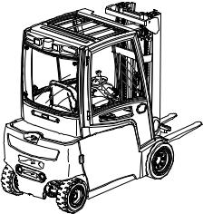
1Application
The EFG is a threeor four-wheel electric sit-down counterbalanced truck. It is cantilevered and the load handler mounted on the front of the truck can unload lorries without hindrance and deposit the load on ramps or in aisles. Closed bottom pallets can also be lifted.
Truck models and maximum capacity:
Type |
Max. capacity |
Load centre of gravity |
|
|
|
EFG 213 |
1,300 kg |
500 mm |
|
|
|
EFG 215 |
1500 kg |
500 mm |
|
|
|
EFG 216k |
1600 kg |
500 mm |
|
|
|
EFG 216 |
1600 kg |
500 mm |
|
|
|
EFG 218k |
1800 kg |
500 mm |
|
|
|
EFG 218 |
1800 kg |
500 mm |
|
|
|
EFG 220 |
2000 kg |
500 mm |
|
|
|
EFG 316k |
1600 kg |
500 mm |
|
|
|
EFG 316 |
1600 kg |
500 mm |
|
|
|
EFG 318k |
1800 kg |
500 mm |
|
|
|
EFG 318 |
1800 kg |
500 mm |
|
|
|
EFG 320 |
2000 kg |
500 mm |
|
|
|
0708.GB
B 1
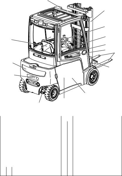
2Assemblies and Functional Description
2
3
4
5
1
6
7
8
15
9
14
 10
10
11
12
13
Item |
Description |
Item |
Description |
||
|
|
|
|
|
|
1 |
t |
Driver's seat |
8 |
t |
Load handler |
|
|
|
|
|
|
2 |
t |
Overhead guard |
9 |
t |
Fork carriage |
|
|
|
|
|
|
3 |
t |
Mast |
10 |
t Drive axle |
|
|
|
|
|
|
|
4 |
t |
Steering wheel |
11 |
t Battery door |
|
|
|
|
|
|
|
|
o |
Multifunction steering wheel |
12 |
o |
On-board charger |
|
|
|
|
|
(in battery compartment) |
5 |
t |
SOLOPILOT |
13 |
t Steering axle |
|
|
|
|
|
|
|
|
o |
MULTIPILOT |
14 |
t Trailer coupling |
|
|
|
|
|
|
|
6 |
t |
Dashboard control panel |
15 |
t Counterweight |
|
|
|
|
|
|
|
7t EMERGENCY DISCONNECT switch
t = Standard equipment |
o = Optional equipment |
0708.GB
B 2
2.1Truck
Safety mechanisms: The overhead guard (2) protects the driver from falling objects. Pressing the EMERGENCY DISCONNECT switch rapidly disconnects all electrical functions in hazardous situations. Travelling and lifting can only be activated when the driver is seated. The dashboard control panel (6) displays the truck information.
Steering: The travel speed reduces as a function of the steering angle (“CurveControl”). The steering angle is shown in the display.
Operator position: The driver’s seat (1) is a “comfort” seat, the steering column is adjustable. There are storage facilities for paper and the driver's personal items. The control and warning displays on the dashboard control panel (6) enable the system to be monitored during operation, thereby ensuring a very high level of safety.
Electrical/Electronic System: The driver can choose from five travel programs, depending on the load and the environment: from maximum performance to energy saving. The latest threephase system using a CAN Bus allows for rapid troubleshooting. The advanced controller is simple, safe and flexible.
Drive System and Brakes: The 2-motor front drive provides maximum traction to the drive wheels at all times. Each motor receives the exact power it requires in proportion to the steering angle. The wheels do not spin and energy is converted efficiently.
The mechanical disk brake which acts as a service brake is maintenance-free. Encapsulated, it allows the truck to be used even in hostile environments. The truck also brakes to a halt regeneratively via the traction motors. This minimizes energy consumption.
The parking brake is electrically actuated. It is also used for emergency braking. A warning indicator appears when the parking brake is applied.
Brake system faults are shown on the driver’s display.
Emergency Stop Safety Feature: The emergency stop is controlled by the steering and traction controllers. If an error is detected the truck automatically brakes to a halt. Control displays on the driver’s display indicate the emergency stop. Every time the truck is switched on, the system performs a self-diagnosis which only releases the parking brake (emergency stop) if the functionality test is positive.
Hydraulic System: All functions must be performed sensitively. To ensure greater efficiency, a hydraulic unit and a steering motor operate independently of each other. The micro pressure filter can be replaced from the top (without spilling hydraulic oil).
Mast: The maximum strength steel sections are narrow, allowing for good fork visibility in particular with the three-stage mast. The lift rails and the fork carriage run on permanently-lubricated and hence maintenance-free angled rollers.
0708.GB
B 3
3Standard Version Specifications
ZTechnical specification details in accordance with VDI 2198. Technical modifications and additions reserved.
3.1EFG 213-220 performance data
|
Description |
|
|
EFG |
|
|
|
|
|
|
|
|
|
|
|
|
|
213 |
215 |
216k |
218k |
220 |
|
|
|
|
|
|
|
|
|
|
|
|
|
216 |
218 |
|
|
|
|
|
|
|
|
|
|
Q |
Capacity |
1300 |
1500 |
1600 |
1800 |
2000 |
kg |
|
(where C = 500 mm) *) |
|
|
|
|
|
|
C |
Load centre of gravity |
500 |
500 |
500 |
500 |
500 |
mm |
distance |
|||||||
|
|
|
|
|
|
|
|
|
Travel speed |
16/16 |
16/16 |
16/16 |
16/16 |
16/16 |
km/h |
|
with / without load |
||||||
|
|
|
|
|
|
|
|
|
|
|
|
|
|
|
|
|
Raise lift speed |
0.48/0.60 |
0.46/0.60 |
0.49/0.60 |
0.44/0.55 |
0.40/0.55 |
m/s |
|
with / without load |
||||||
|
|
|
|
|
|
|
|
|
|
|
|
|
|
|
|
|
Lower lift speed |
0.55/0.55 |
0.55/0.55 |
0.55/0.55 |
0.55/0.55 |
0.55/0.55 |
m/s |
|
with / without load |
||||||
|
|
|
|
|
|
|
|
|
|
|
|
|
|
|
|
|
Gradeability |
|
|
7.3/12.3 |
6.2/10.7 |
|
|
|
(30 min) |
7.6/12.5 |
7.3/12.3 |
|
|
5.7/10.4 |
% |
|
7.0/11.5 |
5.9/10.5 |
|||||
|
with / without load |
|
|
|
|
||
|
|
|
|
|
|
|
|
|
Max. gradeability |
|
|
|
26.0/35.0 |
|
|
|
(5 min) |
28.0/35.0 |
27.0/35.0 |
27.0/35.0 |
|
24.0/35.0 |
% |
|
25.0/35.0 |
||||||
|
with / without load |
|
|
|
|
|
|
|
|
|
|
|
|
|
|
|
Acceleration (10m) |
3.6/3.2 |
3.8/3.4 |
3.8/3.4 |
3.9/3.5 |
4.0 / 3.5 |
s |
|
with / without load |
||||||
|
|
|
|
|
|
|
|
|
|
|
|
|
|
|
|
*) with vertical mast
0708.GB
B 4
3.2EFG 316-320 performance data
|
Description |
|
|
EFG |
|
|
|
|
|
|
|
|
|
|
|
|
|
316k |
316 |
318k |
318 |
320 |
|
|
|
|
|
|
|
|
|
|
Capacity |
|
|
|
|
|
|
Q |
(where C = |
1600 |
1600 |
1800 |
1800 |
2000 |
kg |
|
500 mm) *) |
|
|
|
|
|
|
|
|
|
|
|
|
|
|
C |
Load centre of |
500 |
500 |
500 |
500 |
500 |
mm |
|
gravity distance |
|
|
|
|
|
|
|
|
|
|
|
|
|
|
|
Travel speed |
17.0/17.0 |
17.0/17.0 |
17.0/17.0 |
17.0/17.0 |
17.0/17.0 |
km/h |
|
with / without load |
||||||
|
|
|
|
|
|
|
|
|
Raise lift speed |
0.49/0.60 |
0.49/0.60 |
0.44/0.55 |
0.44/0.55 |
0.40/0.55 |
m/s |
|
with / without load |
||||||
|
|
|
|
|
|
|
|
|
Lower lift speed |
0.55/0.55 |
0.55/0.55 |
0.55/0.55 |
0.55/0.55 |
0.55/0.55 |
m/s |
|
with / without load |
||||||
|
|
|
|
|
|
|
|
|
Gradeability |
|
|
|
|
|
|
|
(30 min) |
7.3/12.3 |
7/11.5 |
6.2/10.7 |
5.9/10.5 |
5.7/10.4 |
% |
|
with / without load |
|
|
|
|
|
|
|
|
|
|
|
|
|
|
|
Max. gradeability |
|
|
|
|
|
|
|
(5 min rating) |
27/35 |
27/35 |
26/35 |
25/35 |
24/35 |
% |
|
with / without load |
|
|
|
|
|
|
|
|
|
|
|
|
|
|
|
Acceleration (10m) |
3.8/3.4 |
3.8/3.4 |
3.9/3.5 |
3.9/3.5 |
4/3.5 |
s |
|
with / without load |
|
|
|
|
|
|
|
|
|
|
|
|
|
|
*) with vertical mast
0708.GB
B 5
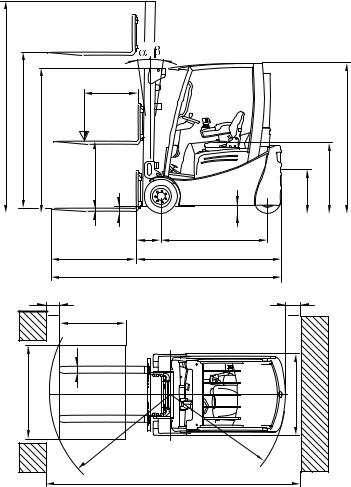
3.3EFG 213-220 dimensions
ZAll dimensions in mm
|
Description |
|
|
EFG |
|
|
|
|
|
|
|
|
|
|
|
|
|
213 |
215 |
216k |
218k |
220 |
|
|
|
|
|
|
|
|
|
|
|
|
|
216 |
218 |
|
|
|
|
|
|
|
|
|
|
h1 |
Mast height retracted |
2000 |
2000 |
2000 |
2000 |
2000 |
|
h2 |
Free lift |
150 |
150 |
150 |
150 |
150 |
|
h3 |
Lift |
3000 |
3000 |
3000 |
3000 |
3000 |
|
h4 |
Mast height extended |
3560 |
3560 |
3560 |
3587 |
3587 |
|
h6 |
Overhead guard height |
2040 |
2040 |
2040 |
2040 |
2040 |
|
h7 |
Seat height |
920 |
920 |
920 |
920 |
920 |
|
h10 |
Tow height |
560 |
560 |
560 |
560 |
560 |
|
L1 |
Length including forks |
2924 |
2924 |
3037 |
3037 |
3145 |
|
|
|
||||||
3145 |
3145 |
||||||
|
|
|
|
|
|||
|
|
|
|
|
|
|
|
L |
Length incl. fork shank 1) |
1774 |
1774 |
1887 |
1887 |
1995 |
|
|
|
||||||
|
|
||||||
2 |
|
|
|
1995 |
1995 |
|
|
|
|
|
|
|
|||
|
|
|
|
|
|
|
|
b1 |
Overall width |
1060 |
1060 |
1060 |
1120 |
1120 |
|
|
|
|
|
|
|
|
|
e |
Fork width |
100 |
100 |
100 |
100 |
100 |
|
|
|
|
|
|
|
|
|
m1 |
Ground clearance |
80 |
80 |
80 |
80 |
80 |
|
with load below mast |
|||||||
|
|
|
|
|
|
|
|
m2 |
Centre wheel base ground |
100 |
100 |
100 |
100 |
100 |
|
clearance |
|||||||
Ast |
Working Aisle Width |
3226 |
3226 |
3339 |
3339 |
3446 |
|
800 x 1200 longitudinal pallets |
3446 |
3446 |
|||||
|
|
|
|
|
|
|
|
Ast |
Working Aisle Width |
3104 |
3104 |
3216 |
3216 |
3323 |
|
1000 x 1200 traverse pallets |
3323 |
3323 |
|||||
|
|
|
|
|
|
|
|
Wa |
Turning radius |
1440 |
1440 |
1548 |
1548 |
1655 |
|
|
|
||||||
1655 |
1655 |
||||||
|
|
|
|
|
|||
|
|
|
|
|
|
|
|
x |
Load distance 1) |
335 |
335 |
340 |
340 |
340 |
|
y |
Wheel base |
1249 |
1249 |
1357 |
1357 |
1465 |
|
|
|
||||||
1465 |
1465 |
||||||
|
|
|
|
|
|||
|
|
|
|
|
|
|
1) = + 25 mm DZ mast
0708.GB
B 6
|
|
c |
|
|
h4 |
Q |
|
|
|
|
|
|
|
|
|
h3 |
|
|
h6 |
|
h1 |
|
|
|
|
h 2 |
|
|
h7 |
|
|
|
|
h10 |
|
s |
m 1 |
|
m 2 |
|
|
x |
y |
|
|
|
l |
|
L 2 |
|
|
|
|
L 1 |
a |
l6 |
a |
|
2 |
2 |
||
|
|||
|
e |
|
|
b12 |
|
b |
|
|
|
||
|
R |
Wa |
|
|
|
A st |
0708.GB
B 7
3.4EFG 316-320 dimensions
ZAll dimensions in mm
|
Description |
|
|
EFG |
|
|
|
|
|
|
|
|
|
|
|
|
|
316k |
316 |
318k |
318 |
320 |
|
|
|
|
|
|
|
|
|
h1 |
Mast height retracted |
2000 |
2000 |
2000 |
2000 |
2000 |
|
h2 |
Free lift |
150 |
150 |
150 |
150 |
150 |
|
h3 |
Lift |
3000 |
3000 |
3000 |
3000 |
3000 |
|
h4 |
Mast height extended |
3560 |
33560 |
3587 |
3587 |
3587 |
|
h6 |
Overhead guard height |
2040 |
2040 |
2040 |
2040 |
2040 |
|
h7 |
Seat height |
920 |
920 |
920 |
920 |
920 |
|
h10 |
Tow height |
410/ |
410/ |
410/ |
410/ |
410/ |
|
580 |
580 |
580 |
580 |
580 |
|||
|
|
||||||
|
|
|
|
|
|
|
|
L1 |
Length including forks |
3140 |
3248 |
3140 |
3248 |
3248 |
|
L2 |
Length including fork shank |
1990 |
2098 |
1990 |
2098 |
2098 |
|
b1 |
Overall width |
1060 |
1060 |
1120 |
1120 |
1120 |
|
e |
Fork width |
100 |
100 |
100 |
100 |
100 |
|
|
|
|
|
|
|
|
|
m1 |
Ground clearance |
80 |
80 |
80 |
80 |
80 |
|
with load below mast |
|||||||
|
|
|
|
|
|
|
|
m2 |
Centre wheel base ground |
100 |
100 |
100 |
100 |
100 |
|
clearance |
|
|
|
|
|
||
Ast |
Working Aisle Width |
3599 |
3725 |
3599 |
3701 |
3701 |
|
800 x 1200 longitudinal pallets |
|||||||
|
|
|
|
|
|
|
|
Ast |
Working Aisle Width |
3403 |
3526 |
3403 |
3526 |
3526 |
|
|
1000 x 1200 traverse pallets |
|
|
|
|
|
|
|
|
|
|
|
|
|
|
Wa |
Turning radius |
1859 |
1985 |
1859 |
1985 |
1985 |
|
x |
Load distance 1) |
340 |
340 |
340 |
340 |
340 |
|
y |
Wheel base |
1400 |
1508 |
1400 |
1508 |
1508 |
|
|
|
|
|
|
|
|
1) = + 25 mm DZ mast
0708.GB
B 8

|
|
c |
|
|
h4 |
Q |
|
|
|
|
|
|
|
|
|
h3 |
|
|
h6 |
|
h1 |
|
|
|
|
h 2 |
|
|
h7 |
|
|
|
|
h10 |
|
s |
m 1 |
|
m 2 |
|
|
x |
y |
|
|
|
l |
|
L 2 |
|
|
|
|
L 1 |
a |
l6 |
a |
|
2 |
2 |
||
|
e |
|
|
b12 |
b13 |
b |
|
|
|
R |
|
Wa |
A st
0708.GB
B 9
3.5EFG 213-220 weights
ZAll dimensions in kg
Description |
|
|
EFG |
|
|
|
|
|
|
|
|
|
|
|
213 |
215 |
216k |
218k |
220 |
|
|
|
|
|
|
|
|
|
|
|
216 |
218 |
|
|
|
|
|
|
|
|
|
Truck weight |
2733 |
2978 |
3000 |
3256 |
3382 |
|
(including battery) |
3057 |
3207 |
||||
|
|
|
||||
|
|
|
|
|
|
|
Front axle load |
1326 |
1310 |
1411 |
1409 |
1501 |
|
(without lifting load) |
1496 |
1520 |
||||
|
|
|
||||
|
|
|
|
|
|
|
Front axle load |
3545 |
3870 |
4052 |
4380 |
4706 |
|
(with lifting load) |
4060 |
4405 |
||||
|
|
|
||||
|
|
|
|
|
|
|
Rear axle load |
1407 |
1668 |
1589 |
1846 |
1881 |
|
(without lifting load) |
1561 |
1686 |
||||
|
|
|
||||
|
|
|
|
|
|
|
Rear axle load |
488 |
608 |
548 |
675 |
676 |
|
(with lifting load) |
597 |
602 |
||||
|
|
|
||||
|
|
|
|
|
|
3.6EFG 316-320 weights
Z All dimensions in kg
Description |
|
|
EFG |
|
|
|
|
|
|
|
|
|
|
|
316k |
316 |
318k |
318 |
320 |
|
|
|
|
|
|
|
|
Truck weight |
3035 |
3001 |
3175 |
3141 |
3306 |
|
(including battery) |
||||||
|
|
|
|
|
||
|
|
|
|
|
|
|
Front axle load |
1380 |
1493 |
1385 |
1499 |
1489 |
|
(without lifting load) |
|
|
|
|
|
|
|
|
|
|
|
|
|
Front axle load |
4004 |
4043 |
4336 |
4367 |
4676 |
|
(with lifting load) |
|
|
|
|
|
|
|
|
|
|
|
|
|
Rear axle load |
1655 |
1508 |
1790 |
1642 |
1817 |
|
(without lifting load) |
|
|
|
|
|
|
|
|
|
|
|
|
|
Rear axle load |
631 |
558 |
638 |
574 |
630 |
|
(with lifting load) |
|
|
|
|
|
|
|
|
|
|
|
|
0708.GB
B 10
3.7EFG 213-220 tyres
Description |
|
EFG 213-216 |
EFG 218 |
EFG 220 |
|
|
|
|
|
|
SE |
18 x 7 - 8, 16 PR |
200/50 - 10 |
|
|
|
|
|
|
|
Rubber |
18 x 7 x 12 1/8“ |
|
|
Tyre size, front |
|
|
|
|
|
180/70 - 8 |
|
|
|
|
|
|
|
|
|
Pneumatic |
Diagonal, |
not available |
|
|
|
16 PR; 7 bar |
|
|
|
|
|
|
|
|
SE |
|
140/55 - 9 |
|
|
|
|
|
|
|
Rubber |
15 x 5 x 11 1/4” |
|
|
Tyre size, rear |
|
|
|
|
|
15 x 4.5 - 8 |
|
|
|
|
|
|
|
|
|
Pneumatic |
Diagonal, |
not available |
|
|
|
12 PR; 7 bar |
|
|
|
|
|
|
|
ZPermissible tyres: See chapter F “Forklift Truck Maintenance”. For any queries please contact your Jungheinrich customer adviser.
3.8 |
EFG 316-320 tyres |
|
|
|
|
|
|
|
|
|
|
|
Description |
|
EFG 316 |
EFG 318 |
EFG 320 |
|
|
|
|
|
|
|
|
SE |
18 x 7 - 8, 16 PR |
200/50 - 10 |
|
|
|
|
|
|
|
|
|
Rubber |
18 x 7 x 12 1/8” |
18 x 8 x 12 1/8” |
|
|
Tyre size, front |
|
|
|
|
|
|
180/70 - 8 |
|
|
|
|
|
|
|
|
|
|
|
Pneumatic |
Diagonal, |
not available |
|
|
|
|
16 PR; 7 bar |
|
|
|
|
|
|
|
|
|
|
SE |
|
16 x 6 - 8 |
|
|
|
|
|
|
|
|
|
Rubber |
16 x 5 x 10 1/2” |
|
|
|
Tyre size, rear |
|
|
|
|
|
|
150/75 - 8 |
|
|
|
|
|
|
|
|
|
|
|
Pneumatic |
Diagonal, |
not available |
|
|
|
|
16 PR; 7 bar |
|
|
|
|
|
|
|
|
ZPermissible tyres: See chapter F “Forklift Truck Maintenance”. For any queries please contact your Jungheinrich customer adviser.
0708.GB
B 11
3.9EFG 213-320 mast versions
ZAll dimensions in mm
VDI 3596 |
Lift |
Free lift |
Height |
Height extended |
|||
|
|
|
|
retracted |
|
|
|
Description |
h3 |
h2 |
h1 |
|
h4 |
||
|
|
EFG 213/ |
EFG 218k/ |
|
EFG 213/ |
|
EFG 218k/ |
|
|
215/216k/ |
218/220/ |
|
215/216k/ |
218/220/ |
|
|
|
216/316/ |
318/318k/ |
|
216/316/ |
|
318/318k/ |
|
|
316k |
320 |
|
316k |
|
320 |
|
|
|
|
|
|
|
|
|
2300 |
150 |
1650 |
2850 |
|
2885 |
|
|
|
|
|
|
|
|
|
|
3000 |
150 |
2000 |
3550 |
|
3585 |
|
|
|
|
|
|
|
|
|
|
3100 |
150 |
2050 |
3650 |
|
3685 |
|
|
|
|
|
|
|
|
|
|
3300 |
150 |
2150 |
3850 |
|
3885 |
|
|
|
|
|
|
|
|
|
ZT |
3600 |
150 |
2300 |
4150 |
|
4185 |
|
|
|
|
|
|
|
|
|
|
4000 |
150 |
2500 |
4550 |
|
4585 |
|
|
|
|
|
|
|
|
|
|
4500 |
150 |
2800 |
5050 |
|
5085 |
|
|
|
|
|
|
|
|
|
|
5000 |
150 |
3050 |
5550 |
|
5585 |
|
|
|
|
|
|
|
|
|
|
5500 |
150 |
3400 |
6050 |
|
6085 |
|
|
|
|
|
|
|
|
|
|
2300 |
1055 |
990 |
1605 |
2850 |
|
2915 |
|
|
|
|
|
|
|
|
|
3000 |
1405 |
1340 |
1955 |
3550 |
|
3615 |
|
|
|
|
|
|
|
|
ZZ |
3100 |
1455 |
1390 |
2005 |
3650 |
|
3715 |
|
|
|
|
|
|
|
|
3300 |
1555 |
1490 |
2105 |
3850 |
|
3915 |
|
|
|
||||||
|
|
|
|
|
|
|
|
|
3600 |
1705 |
1640 |
2255 |
4150 |
|
4215 |
|
|
|
|
|
|
|
|
|
4000 |
1905 |
1840 |
2455 |
4550 |
|
4615 |
|
|
|
|
|
|
|
|
|
4350 |
1405 |
1340 |
1955 |
4900 |
|
4965 |
|
|
|
|
|
|
|
|
|
4500 |
1455 |
1390 |
2005 |
5050 |
|
5115 |
|
|
|
|
|
|
|
|
|
4800 |
1555 |
1490 |
2105 |
5350 |
|
5415 |
|
|
|
|
|
|
|
|
DZ |
5000 |
1630 |
1565 |
2180 |
5550 |
|
5615 |
|
|
|
|
|
|
|
|
|
5500 |
1805 |
1740 |
2355 |
6050 |
|
6115 |
|
|
|
|
|
|
|
|
|
6000 |
2005 |
1940 |
2555 |
6550 |
|
6615 |
|
|
|
|
|
|
|
|
|
6500 |
2255 |
2190 |
2805 |
7050 |
|
7115 |
|
|
|
|
|
|
|
|
0708.GB
B 12
3.10 EN norms |
|
EFG 213-220 |
|
noise emission level: |
66 dB(A) |
EFG 316-320 |
|
noise emission level: |
67 dB(A) |
|
in accordance with EN 12053 as harmonised with |
|
ISO 4871. |
ZThe noise emission level is calculated in accordance with standard procedures and takes into account the noise level when travelling, lifting and when idle. The noise level is measured at the driver’s ear.
EFG 213-220 vibration: |
0.53 m/s2 |
EFG 316-320 vibration: |
0.51 m/s2 |
In accordance with EN 13059.
ZThe vibration acceleration acting on the body in the operating position is, in accordance with standard procedures, the linearly integrated, weighted acceleration in the vertical direction. It is calculated when travelling over bumps at constant speed.
Electromagnetic compatibility (EMC)
The manufacturer confirms that equipment complies with tolerance levels for electromagnetic emissions and resistance as well as static electricity discharge testing in accordance with EN 12895 including the normative procedures contained therein.
ZNo changes to electric or electronic components or their arrangement may be made without the written agreement of the manufacturer.
3.11Conditions of use
Ambient temperature
- operating at -20 °C to 40 °C
ZSpecial equipment and authorisation are required if the truck is to be constantly used in conditions of extreme temperature or air humidity fluctuations.
0708.GB
B 13

4Identification points and data plates
FWarnings and notices such as load charts, strap points and data plates must be legible at all times. Replace if necessary.
18
19
17
16
XXX
20
21
22

 29
29
23
(mm) |
Q (kg) |
D (mm)
|
|
24 |
18 |
27 |
25 |
|
26 |
|
|
|
|
|
28 |
|
0708.GB
B 14
Item |
Description |
|
|
16 |
Do not travel with raised load or mast forward tilt with raised load |
|
|
17 |
Wear seatbelt |
|
|
18 |
Strap points |
|
|
19 |
Tipover caution, no passengers |
|
|
20 |
Lift limit |
|
|
21 |
Do not step onto or beneath the load, risk of trapping |
|
|
22 |
Read the operating instructions |
|
|
23 |
Capacity |
|
|
24 |
Risk of trapping, in chassis behind the battery door |
|
|
25 |
Data plate |
|
|
26 |
Jack contact points |
|
|
27 |
Serial number, on chassis behind the battery door |
|
|
28 |
Add hydraulic oil |
|
|
29 |
Test sticker (o) |
|
|
0708.GB
B 15
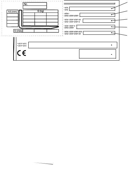
4.1Truck data plate
30 |
31 |
32 |
33 |
34 |
41 |
40 |
39 |
38 |
37 |
 36
36  35
35
Item |
Description |
Item |
Description |
|
|
|
|
30 |
Type |
36 |
Manufacturer |
|
|
|
|
31 |
Serial no. |
37 |
Min./max. battery weight (kg) |
|
|
|
|
32 |
Rated capacity (kg) |
38 |
Output (kW) |
|
|
|
|
33 |
Battery: Voltage (V) |
39 |
Load centre of gravity (mm) |
|
|
|
|
34 |
Net weight w.o. battery (kg) |
40 |
Year of manufacture |
|
|
|
|
35 |
Manufacturer’s logo |
41 |
Option |
|
|
|
|
ZFor queries regarding the truck or ordering spare parts always quote the truck serial number (31).
4.2Truck load chart
The capacity plate (23) gives the capacity (Q) of the truck in kg for a vertical mast. The maximum capacity is shown as a table with a given load centre of gravity D (in mm) and the required lift height H (in mm).
Example of how to calculate the maximum capacity:
With a load centre of gravity D of 600 mm and a maximum lift height H of 3600 mm. the max. capacity Q is 1105 kg.
Example:
23
4250 |
850 |
850 |
600 |
|
1105 |
1105 |
|
||
3600 |
850 |
|||
1250 |
1250 |
850 |
||
2900 |
||||
|
|
|
||
|
500 |
600 |
700 |
0708.GB
B 16
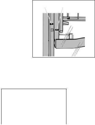
The arrow shape markings (42 and 43)
on the inner and outer masts show the 42 43 driver when the prescribed lift limits have
been reached.
4.3Fork load diagram (basic model)
The fork load diagram give the truck’s capacity Q in kg. The maximum capacity for the various load centres of gravity (D in mm) is shown in chart form.
4.4Attachment load chart
The attachment load chart gives the truck’s capacity Q in combination with the respective attachment in kg. The serial number specified in the load chart must match the data plate of the attachment, as the capacity for each truck is specifically indicated by the manufacturer. It is shown in the same way as the truck’s capacity and can be determined accordingly.
ZFor loads with a centre of gravity above 500 mm upward, the capacities are reduced by the difference of the altered centre of gravity.
0708.GB
B 17
 Loading...