


DFG / TFG 425s - 435s
Operating instructions
51158585
07.10
11.09 -
G
DFG 425s
DFG 430s
DFG 435s
TFG 425s
TFG 430s
TFG 435s

Declaration of Conformity
Jungheinrich AG, Am Stadtrand 35, D-22047 Hamburg
Manufacturer or his authorized representative in the Community
Type |
Option |
Serial No. |
Year of |
|
|
|
construction |
|
|
|
|
DFG 425s |
|
|
|
DFG 430s |
|
|
|
DFG 435s |
|
|
|
TFG 425s |
|
|
|
TFG 430s |
|
|
|
TFG 435s |
|
|
|
|
|
|
|
Additional information
Authorised signatory
Date
GEU Declaration of Conformity
The signatories hereby certify that the specified powered industrial truck conforms to the EU Directive 2006/42/EC (Machine Directive) and 2004/108/EEC (ElectroMagnetic Compatibility, EMC) including their amendments as translated into national legislation of the member countries. The signatories are individually empowered in each case to compile the technical documentation.
07.10 EN
3
4
07.10 EN

07.10 EN
Foreword
Notes on the operating instructions
The present ORIGINAL OPERATING INSTRUCTIONS are designed to provide sufficient instruction for the safe operation of the industrial truck. The information is provided clearly and concisely. The chapters are arranged by letter and the pages are numbered continuously.
The operator manual details different industrial truck models. When operating and servicing the industrial truck, make sure that the particular section applies to your truck model.
Our trucks are subject to ongoing development. Jungheinrich reserves the right to alter the design, equipment and technical features of the system. No guarantee of particular features of the truck should therefore be assumed from the present operating instructions.
Safety notices and text mark-ups
Safety instructions and important explanations are indicated by the following graphics:
DANGER!
Indicates an extremely hazardous situation. Failure to comply with this instruction will result in severe irreparable injury and even death.
WARNING!
Indicates an extremely hazardous situation. Failure to comply with this instruction may result in severe irreparable injury and even death.
CAUTION!
Indicates a hazardous situation. Failure to comply with this instruction may result in slight to medium injury.
NOTE
Indicates a material hazard. Failure to comply with this instruction may result in material damage.
ZUsed before notices and explanations.
t Indicates standard equipment
oIndicates optional equipment
Copyright
Copyright of these operating instructions remains with JUNGHEINRICH AG.
5
Jungheinrich Aktiengesellschaft
Am Stadtrand 35
22047 Hamburg - Germany
Tel: +49 (0) 40/6948-0
www.jungheinrich.com
07.10 EN
6
Table of Contents |
|
|
A |
Correct Use and Application ................................................... |
11 |
1 |
General.................................................................................................... |
11 |
2 |
Correct application................................................................................... |
11 |
3 |
Approved application conditions.............................................................. |
12 |
4 |
Proprietor responsibilities ........................................................................ |
13 |
5 |
Adding attachments and/or accessories.................................................. |
13 |
B |
Truck Description .................................................................... |
15 |
1 |
Application ............................................................................................... |
15 |
1.1 |
Truck models and rated capacity............................................................. |
15 |
2 |
Assemblies and Functional Description................................................... |
16 |
2.1 |
Assembly Overview ................................................................................. |
16 |
2.2 |
Functional Description ............................................................................. |
17 |
3 |
Technical Specifications .......................................................................... |
19 |
3.1 |
Performance data .................................................................................... |
19 |
3.2 |
Dimensions.............................................................................................. |
21 |
3.3 |
Weights.................................................................................................... |
23 |
3.4 |
Mast versions .......................................................................................... |
24 |
3.5 |
Tyre type.................................................................................................. |
25 |
3.6 |
Engine Data............................................................................................. |
26 |
3.7 |
EN norms................................................................................................. |
27 |
3.8 |
Conditions of use..................................................................................... |
28 |
3.9 |
Electrical requirements ............................................................................ |
28 |
4 |
Identification points and data plates ........................................................ |
29 |
4.1 |
Data plate ................................................................................................ |
31 |
4.2 |
Truck capacity plate................................................................................. |
32 |
4.3 |
Attachment capacity plate ....................................................................... |
33 |
5 |
Stability .................................................................................................... |
33 |
C |
Transport and Commissioning ................................................ |
35 |
1 |
Transport ................................................................................................. |
35 |
2 |
Truck laden.............................................................................................. |
35 |
2.1 |
Centre of gravity of the truck ................................................................... |
35 |
2.2 |
Lifting the truck by crane ......................................................................... |
36 |
2.3 |
Loading with another industrial truck ....................................................... |
37 |
3 |
Securing the truck during transport ......................................................... |
38 |
4 |
Using the Truck for the First Time ........................................................... |
39 |
07.10 EN
7
D |
Fuelling the Truck.................................................................... |
41 |
1 |
General.................................................................................................... |
41 |
1.1 |
Safety regulations for handling diesel fuel and LPG................................ |
41 |
1.2 |
Gas system relief valve ........................................................................... |
43 |
2 |
Adding diesel ........................................................................................... |
44 |
2.1 |
Fuelling .................................................................................................... |
44 |
2.2 |
Fuelling with fuel containers .................................................................... |
45 |
3 |
LPG containers........................................................................................ |
46 |
3.1 |
LPG bottles.............................................................................................. |
46 |
3.2 |
Liquid gas tank ........................................................................................ |
49 |
4 |
Fuel level indicator................................................................................... |
50 |
4.1 |
Display unit .............................................................................................. |
50 |
4.2 |
Level indicator for LPG bottles (o) ........................................................... |
50 |
E |
Operation ................................................................................ |
51 |
1 |
Safety Regulations for the Operation of the Forklift Truck....................... |
51 |
2 |
Displays and Controls.............................................................................. |
53 |
2.1 |
Control panel with display unit................................................................. |
56 |
2.2 |
Control panel buttons .............................................................................. |
59 |
2.3 |
Display..................................................................................................... |
62 |
3 |
Preparing the Truck for Operation ........................................................... |
63 |
3.1Checks and operations to be performed before starting daily operation . 63
3.2 |
Entry and exit........................................................................................... |
65 |
3.3 |
Trucks with reduced headroom X (o) ...................................................... |
65 |
3.4 |
Setting up the operator position............................................................... |
66 |
3.5 |
Seat Belt .................................................................................................. |
71 |
4 |
Industrial Truck Operation ....................................................................... |
72 |
4.1 |
Safety regulations for truck operation...................................................... |
72 |
4.2 |
Preparing the truck for operation ............................................................. |
74 |
4.3 |
Setting the time........................................................................................ |
77 |
4.4 |
Parking the truck securely ....................................................................... |
78 |
4.5 |
Emergency Disconnect............................................................................ |
79 |
4.6 |
Travel....................................................................................................... |
80 |
4.7 |
Steering ................................................................................................... |
82 |
4.8 |
Brakes ..................................................................................................... |
82 |
4.9 |
Adjusting the forks ................................................................................... |
85 |
4.10 |
Replacing the forks.................................................................................. |
86 |
4.11 |
Lifting, transporting and depositing loads ................................................ |
87 |
4.12 |
Operating the lift mechanism and integrated attachments ...................... |
89 |
4.13 |
Safety instructions for operating additional attachments ......................... |
95 |
4.14 |
Operating additional attachments for the SOLO-PILOT .......................... |
98 |
4.15 |
Operating additional attachments for the Multi Pilot ................................ |
100 |
4.16 |
Fitting additional attachments.................................................................. |
102 |
5 |
Towing trailers ......................................................................................... |
104 |
6 |
Optional equipment ................................................................................. |
106 |
6.1 |
Assistance systems ................................................................................. |
106 |
6.2 |
Steel cab.................................................................................................. |
108 |
6.3 |
Sliding windows ....................................................................................... |
108 |
6.4 |
Automatic / mechanical folding gate........................................................ |
109 |
07.10 EN
8
6.5 |
Panel door ............................................................................................... |
110 |
6.6 |
Operator position extension..................................................................... |
110 |
6.7 |
Heating and air conditioning system........................................................ |
111 |
6.8 |
Driver’s seat heating / backrest extension............................................... |
114 |
6.9 |
Removable load backrest ........................................................................ |
115 |
6.10 |
Lift cutout override ................................................................................... |
115 |
6.11 |
Sideshifter centre position ....................................................................... |
116 |
6.12 |
Fire extinguisher ...................................................................................... |
116 |
6.13 |
Rockinger coupling with hand lever or remote control............................. |
117 |
6.14 |
Camera system ....................................................................................... |
118 |
6.15 |
Optional equipment for working in dusty environments........................... |
119 |
6.16 |
Roof window wiper .................................................................................. |
119 |
6.17 |
Control layout “N” .................................................................................... |
120 |
7 |
Troubleshooting....................................................................................... |
121 |
7.1 |
Troubleshooting....................................................................................... |
121 |
7.2 |
Operating the truck without its own drive system .................................... |
126 |
F |
Industrial Truck Maintenance .................................................. |
131 |
1 |
Operational Safety and Environmental Protection................................... |
131 |
2 |
Maintenance Safety Regulations............................................................. |
132 |
3 |
Servicing and Inspection ......................................................................... |
137 |
4 |
Maintenance checklist ............................................................................. |
138 |
4.1 |
Maintenance checklist DFG..................................................................... |
138 |
4.2 |
Maintenance checklist TFG ..................................................................... |
143 |
5 |
Lubricants and Lubrication Schedule ...................................................... |
148 |
5.1 |
Handling consumables safely.................................................................. |
148 |
5.2 |
Lubrication Schedule ............................................................................... |
150 |
5.3 |
Consumables........................................................................................... |
151 |
6 |
Maintenance and repairs ......................................................................... |
153 |
6.1 |
Preparing the truck for maintenance and repairs .................................... |
153 |
6.2 |
Opening the rear panel............................................................................ |
153 |
6.3 |
Unlocking the engine bonnet ................................................................... |
154 |
6.4 |
Opening the engine cover ....................................................................... |
155 |
6.5 |
Checking the wheel attachments............................................................. |
157 |
6.6 |
Hydraulic system ..................................................................................... |
158 |
6.7 |
Engine maintenance................................................................................ |
161 |
6.8 |
Checking electrical fuses......................................................................... |
175 |
6.9 |
Starter battery.......................................................................................... |
181 |
6.10 |
Exhaust system ....................................................................................... |
182 |
6.11 |
Seat belt maintenance............................................................................. |
183 |
6.12 |
Restoring the truck to service after maintenance and repairs ................. |
184 |
7 |
Decommissioning the industrial truck ...................................................... |
185 |
7.1 |
Prior to decommissioning ........................................................................ |
186 |
7.2 |
During decommissioning ......................................................................... |
186 |
7.3 |
Restoring the truck to service after decommissioning ............................. |
187 |
8 |
Safety tests to be performed at intervals and after unusual incidents ..... |
188 |
9 |
Final de-commissioning, disposal............................................................ |
189 |
10 |
Human vibration measurement ............................................................... |
189 |
07.10 EN
9
10
07.10 EN

A Correct Use and Application
1General
The industrial truck described in the present operating instructions is designed for lifting, lowering and transporting load units.
It must be used, operated and serviced in accordance with the present instructions. Any other type of use is beyond the scope of application and can result in damage to personnel, the industrial truck or property.
2Correct application
NOTE
The maximum load and load distance are indicated on the load chart and must not be exceeded.
The load must rest on the load handler or be lifted by an attachment approved by the manufacturer.
The load must rest on the back of the fork carriage and centrally between the forks.
–Lifting and lowering of loads.
–Transporting lowered loads over short distances.
–Do not travel with a raised load (>30 cm).
–Do not carry or lift passengers.
–Do push or pull load units.
–Occasional towing of trailer loads.
–When towing trailer loads the load must be secured on the trailer.
–The permissible trailer load must not be exceeded.
07.10 EN
11
3Approved application conditions
DANGER!
Do not exceed the permissible surface and spot load limits on the travel routes. At blind spots get a second person to assist.
The driver must ensure that the loading dock / ramp cannot move or come loose during loading / unloading.
–Operation in industrial and commercial environments.
–Permissible temperature range -20°C to 40°C.
–Operation only on secure, level surfaces with sufficient capacity.
–Operation only on routes that are visible and approved by the proprietor.
–Negotiating inclines up to a maximum of 15 %.
–Do not negotiate inclines crosswise or at an angle. Transporting loads downhill.
–Operation in partially public traffic.
WARNING!
Extreme conditions
XSpecial equipment and authorisation are required if the truck is to be constantly used in extreme conditions, especially in dusty or corrosive atmospheres.
XThe truck is not authorised for use in areas at risk of explosion.
XIn adverse weather conditions (thunder, lightning) the industrial truck must not be operated outside or in endangered areas.
07.10 EN
12

4Proprietor responsibilities
For the purposes of the present operating instructions the “proprietor” is defined as any natural or legal person who either uses the industrial truck himself, or on whose behalf it is used. In special cases (e.g. leasing or renting) the proprietor is considered the person who, in accordance with existing contractual agreements between the owner and user of the industrial truck, is charged with operational duties.
The proprietor must ensure that the industrial truck is used only for the purpose for which it is intended and that there is no danger to life and limb of the user and third parties. Furthermore, accident prevention regulations, safety regulations and operating, servicing and repair guidelines must be followed. The proprietor must ensure that all users have read and understood these operating instructions.
NOTE
Failure to comply with the operating instructions shall invalidate the warranty. The same applies if improper work is carried out on the truck by the customer or third parties without the permission of the manufacturer.
5Adding attachments and/or accessories
Adding accessories
The mounting or installation of additional equipment which affects or enhances the performance of the forklift truck requires the written permission of the manufacturer. Local authority approval may also need to be obtained.
Local authority approval does not however constitute the manufacturer’s approval.
07.10 EN
13
14
07.10 EN
B Truck Description
1Application
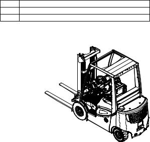
The DFG / TFG 425s - 435s is a four-wheel IC motor sit-down forklift truck. The DFG series are diesel engine trucks, while the TFG series are fitted with a petrol engine for LPG operation.
The DFG / TFG 425s - 435s is a cantilever counterbalanced truck which can lift, transport and deposit loads using the load handler attached in front.
Closed bottom pallets can also be lifted.
The DFG / TFG 425s - 435s is equipped with a hydrostatic drive. The combustion engine drives a high pressure pump for the hydraulic functions and two hydraulic motors to drive wheels.
1.1Truck models and rated capacity
The rated capacity depends on the model. The rated capacity can be derived from the model description.
DFG425
DFG Model Description
4Series
25 Rated capacity x 100 kg
The rated capacity does not generally match the permissible capacity. The capacity can be found on the load chart attached to the rack.
07.10 EN
15
2Assemblies and Functional Description
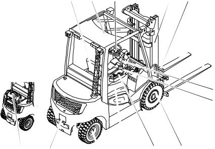
2.1Assembly Overview
1 |
2 |
3 |
4 |
5 |
 6
6
 7
7
8
15 |
14 |
13 |
12 |
11 |
10 |
9 |
|
Item |
Description |
Item |
Description |
||
|
|
|
|
|
|
1 |
t |
Driver's seat |
9 |
t |
Drive |
|
|
|
|
|
|
2 |
t |
Overhead guard |
10 |
t |
Emergency Disconnect switch |
|
|
|
|
|
|
3 |
t |
Steering wheel |
11 |
t |
Engine bonnet |
|
|
|
|
|
|
4 |
t |
Mast |
12 |
t |
Steer axle |
|
|
|
|
|
|
5 |
t |
Fork carriage |
13 |
t |
Counterweight |
|
|
|
|
|
|
6 |
t |
Fork tines |
14 |
t |
Trailer coupling |
|
|
|
|
|
|
7 |
t |
Lift mechanism control |
15 |
t |
LPG bottle (TFG only) |
|
|
|
|
|
|
8 |
t |
Control / display unit |
|
|
|
|
|
|
|
|
|
|
t= Standard equipment |
|
o= Optional equipment |
||
|
|
|
|
|
|
07.10 EN
16
2.2Functional Description
Chassis
The chassis, in conjunction with the counterweight, forms the supporting base structure of the truck. It is used to support the main components.
The hydraulic oil reservoir is integrated on the right-hand side and the fuel tank for the DFG series is on the left side in the chassis.
Operator position and overhead guard
The overhead guard (2) comes in a range of models and protects the driver from falling objects and other external influences.
All the controls are ergonomically arranged. The steering column and driver's seat can be adjusted individually.
The controls and warnings on the display unit (8) enable the system to be monitored during operation, thereby ensuring a very high level of safety.
Steering
The steer cylinder of the hydrostatic steering is integrated in the steer axle (12) and is controlled by the power steering. The steer axle is fully floating in the chassis to ensure excellent grip even on non-level surfaces.
Wheels
All wheels are located within the truck geometry. A choice of pneumatic or superelastic tyres are available.
Engine
High performance, water-cooled diesel and LPG engines with long useful lives and low consumption and emission levels.
Electrical system
12 volt system with threephase alternator. A start block prevents malfunctions when the truck is powered up. For diesel engines, a rapid pre-heat system is installed; LPG motors have an electronic ignition system for rapid and trouble-free engine starting. The key switch is used to stop the engine.
07.10 EN
17
Drive system and brakes
Both drive wheels are powered by individual hydraulic motors which in turn are driven by a hydraulic pump. Forward/reverse or neutral can be set with the travel direction switch on the control panel (7).
The truck brakes to a halt via the hydraulic motors, keeping energy consumption to a minimum. The truck can brake more quickly if you also apply the service brake.
The parking brake is an automatic multi-plate brake that can also be applied manually.
Hydraulic system
A multi-pilot valve allows for sensitive operation of the functions via the controls. A speed-controlled hydraulic pump ensures a proportionate and efficient supply to the hydraulic functions.
Mast
Two or three-stage masts, optionally with free lift function; narrow mast sections ensure excellent visibility of the forks and attachments. Fork carriage and mast run on permanently lubricated and hence maintenance-free support rollers.
Attachments
The trucks can be optionally fitted with mechanical and hydraulic attachments.
07.10 EN
18
3Technical Specifications
All technical details refer to standard trucks. Values indicated with *) may vary, depending on the
types of equipment used (e.g. mast, cabin, tyres etc.).
ZTechnical data specified in accordance with VDI 2198. Technical modifications and additions reserved.
3.1Performance data
DFG 425s-435s
|
Description |
|
DFG 425s |
DFG 430s |
DFG 435s |
|
|
|
|
|
|
|
|
Q |
Capacity |
|
2500 |
3000 |
3500 |
kg |
(where C = 500 mm) 1) |
||||||
|
|
|
|
|
|
|
C |
Load centre distance |
500 |
500 |
500 |
mm |
|
|
|
|
|
|
|
|
|
Travel speed* |
with / |
19.6/19.6 |
20.8/20.8 |
20.8/20.8 |
km/h |
|
without load |
|
||||
|
|
|
|
|
|
|
|
|
|
|
|
|
|
|
Lift speed, with / without |
0.56/0.56 |
0.56/0.56 |
0.48/0.48 |
m/s |
|
|
load |
|
|
|
|
|
|
Lowering speed |
with / |
0.56/0.56 |
0.56/0.56 |
0.56/0.56 |
m/s |
|
without load |
|
||||
|
|
|
|
|
|
|
|
|
|
|
|
|
|
|
Gradeability 2)* |
27 |
24 |
21 |
% |
|
|
with / without load |
|||||
|
|
|
|
|
||
|
|
|
|
|
|
|
|
Acceleration* |
with / |
4.9/4.4 |
5.4/4.6 |
5.4/4.7 |
s |
|
without load to 15 m |
|||||
|
|
|
|
|
||
|
|
|
|
|
|
|
|
Available working |
160 |
160 |
160 |
bar |
|
|
pressure for attachments |
|||||
|
|
|
|
|
||
|
|
|
|
|
|
|
|
Oil flow for attachments |
30 |
30 |
30 |
l/min |
|
|
|
|
|
|
|
|
1)for vertical mast.
2)The values shown represent the maximum gradeability to overcome short differences in height and surface unevenness (surface edges). The truck must not operate on inclines of more than 15%.
07.10 EN
19
TFG 425s-435s
|
Description |
|
TFG 425s |
TFG 430s |
TFG 435s |
|
|
|
|
|
|
|
|
Q |
Capacity |
|
2500 |
3000 |
3500 |
kg |
(where C = 500 mm) 1) |
||||||
|
|
|
|
|
|
|
C |
Load centre distance |
500 |
500 |
500 |
mm |
|
|
|
|
|
|
|
|
|
Travel speed* |
with / |
19.6/19.6 |
20.8/20.8 |
20.8/20.8 |
km/h |
|
without load |
|
||||
|
|
|
|
|
|
|
|
|
|
|
|
|
|
|
Lift speed, with / without |
0.56/0.56 |
0.56/0.56 |
0.48/0.48 |
m/s |
|
|
load |
|
|
|
|
|
|
Lowering speed |
with / |
0.56/0.56 |
0.56/0.56 |
0.56/0.56 |
m/s |
|
without load |
|
||||
|
|
|
|
|
|
|
|
|
|
|
|
|
|
|
Gradeability 2)* |
27 |
24 |
21 |
% |
|
|
with / without load |
|||||
|
|
|
|
|
||
|
|
|
|
|
|
|
|
Acceleration* |
with / |
5.7/5.0 |
6.0/5.1 |
6.1/5.2 |
s |
|
without load to 15 m |
|||||
|
|
|
|
|
||
|
|
|
|
|
|
|
|
Available working |
160 |
160 |
160 |
bar |
|
|
pressure for attachments |
|||||
|
|
|
|
|
||
|
|
|
|
|
|
|
|
Oil flow for attachments |
30 |
30 |
30 |
l/min |
|
|
|
|
|
|
|
|
1)for vertical mast.
2)The values shown represent the maximum gradeability to overcome short differences in height and surface unevenness (surface edges). The truck must not operate on inclines of more than 15%.
07.10 EN
20
3.2Dimensions
DFG / TFG 425s-435s
|
Description |
|
VFG |
|
|
|
|
|
|
|
|
|
|
DFG/TFG |
DFG/TFG |
DFG/TFG |
|
|
|
425s |
430s |
435s |
|
|
|
|
|
|
|
a/2 |
Safety distance |
100 |
100 |
100 |
mm |
|
|
|
|
|
|
h1 |
Mast height retracted* |
2315 |
2333 |
2433 |
mm |
h2 |
Free lift* |
150 |
150 |
150 |
mm |
h3 |
Lift* |
3300 |
3300 |
3300 |
mm |
h4 |
Mast height extended* |
3910 |
4070 |
4083 |
mm |
h6 |
Overhead guard height* |
2220 |
2238 |
2238 |
mm |
h7 |
Seat height* |
1058 |
1076 |
1076 |
mm |
h10 |
Coupling height |
380 |
400 |
400 |
mm |
Į |
Mast tilt, fwd.* |
6 |
6 |
6 |
° |
ȕ |
Mast tilt, back* |
8 |
8 |
8 |
° |
l1 |
Overall length, including |
3763 |
3858 |
3948 |
mm |
forks* |
|||||
|
|
|
|
|
|
l2 |
Overall length, including |
2613 |
2708 |
2798 |
mm |
fork shank* |
|||||
|
|
|
|
|
|
b1 |
Overall width* |
1184 |
1320 |
1320 |
mm |
|
|
|
|
|
|
s/e/l |
Fork dimensions* |
40/120/1150 |
45/125/1150 |
50/125/1150 |
mm |
|
|
|
|
|
|
m1 |
Ground clearance with |
125 |
143 |
143 |
mm |
load below mast* |
|||||
m2 |
Ground clearance |
130 |
148 |
148 |
mm |
centre wheelbase* |
|||||
|
Fork carriage ISO 2328, |
2A |
3A |
3A |
|
|
class / type A, B |
|
|||
|
|
|
|
|
|
|
|
|
|
|
|
|
Working aisle width for |
|
|
|
|
Ast |
pallets 800 x 1200 |
4158 |
4260 |
4338 |
mm |
|
longit. |
|
|
|
|
|
|
|
|
|
|
|
Working aisle width for |
|
|
|
|
Ast |
pallets 1000 x 1200 |
3958 |
4060 |
4138 |
mm |
|
traverse |
|
|
|
|
|
|
|
|
|
|
Wa |
Turning radius |
2285 |
2377 |
2455 |
mm |
b13 |
Smallest turning radius |
617 |
641 |
657 |
mm |
x |
Load distance* |
473 |
478 |
483 |
mm |
|
|
|
|
|
|
c |
Load centre of gravity |
500 |
500 |
500 |
mm |
|
|
|
|
|
|
y |
Wheelbase |
1750 |
1820 |
1880 |
mm |
|
|
|
|
|
|
*) The data listed in the table corresponds to the standard version.
07.10 EN
21

22
07.10 EN
3.3Weights
ZAll dimensions in kg.
|
DFG/TFG 425s |
DFG/TFG 430s |
DFG/TFG 435s |
|
|
|
|
Truck weight* |
4080 |
4376 |
4821 |
|
|
|
|
Axle load w.o. load front / rear* |
1943 / 2137 |
1958 / 2488 |
2009 / 2812 |
|
|
|
|
Axle load with load front / rear* |
5833 / 747 |
6578 / 868 |
7339 / 982 |
|
|
|
|
*) The data listed in the table corresponds to the standard version.
07.10 EN
23

3.4Mast versions
ZAll dimensions in mm
DFG/TFG 425s/430s
Mast table
VDI3596 |
Lift h3 |
Free lift h2 |
Retracted |
Extended |
Mast |
|
Description |
|
(425s/435s) |
height h1 |
height h4 (425s/ |
weight (kg) |
|
|
|
|
|
|
||
|
|
|
|
435s) |
|
|
|
|
|
|
|
|
|
|
2900 |
150 |
2115 |
3510/3670 |
700 |
|
|
|
|
|
|
|
|
|
3100 |
150 |
2215 |
3710/3870 |
720 |
|
|
|
|
|
|
|
|
|
3300 |
150 |
2315 |
3910/4070 |
740 |
|
|
|
|
|
|
|
|
|
3500 |
150 |
2415 |
4110/4270 |
760 |
|
|
|
|
|
|
|
|
|
3700 |
150 |
2515 |
4310/4470 |
780 |
|
|
|
|
|
|
|
|
|
4000 |
150 |
2665 |
4610/4770 |
830 |
|
|
|
|
|
|
|
|
ZT |
4300 |
150 |
2865 |
4910/5070 |
865 |
|
|
|
|
|
|
|
|
|
4500 |
150 |
2965 |
5110/5270 |
885 |
|
|
|
|
|
|
|
|
|
4700 |
150 |
3065 |
5310/5470 |
905 |
|
|
|
|
|
|
|
|
|
5000 |
150 |
3215 |
5610/5770 |
935 |
|
|
|
|
|
|
|
|
|
5500 |
150 |
3515 |
6110/6270 |
995 |
|
|
|
|
|
|
|
|
|
5800 |
150 |
3665 |
6410/6570 |
1025 |
|
|
|
|
|
|
|
|
|
6000 |
150 |
3765 |
6610/6770 |
1045 |
|
|
|
|
|
|
|
|
|
2900 |
1480/1380 |
2080 |
3500/3600 |
735 |
|
|
|
|
|
|
|
|
|
3100 |
1580/1480 |
2180 |
3700/3800 |
755 |
|
|
|
|
|
|
|
|
|
3300 |
1680/1580 |
2280 |
3900/4000 |
780 |
|
|
|
|
|
|
|
|
ZZ |
3500 |
1780/1680 |
2380 |
4100/4200 |
800 |
|
|
|
|
|
|
||
3700 |
1880/1780 |
2480 |
4300/4400 |
820 |
||
|
||||||
|
|
|
|
|
|
|
|
4000 |
2030/1930 |
2630 |
4600/4700 |
850 |
|
|
|
|
|
|
|
|
|
4300 |
2230/2130 |
2830 |
4900/5000 |
904 |
|
|
|
|
|
|
|
|
|
4500 |
2330/2230 |
2930 |
5100/5200 |
930 |
|
|
|
|
|
|
|
|
|
4400 |
1480/1380 |
2080 |
5000/5100 |
920 |
|
|
|
|
|
|
|
|
|
4700 |
1580/1480 |
2180 |
5300/5400 |
950 |
|
|
|
|
|
|
|
|
|
5000 |
1680/1580 |
2280 |
5600/5700 |
980 |
|
|
|
|
|
|
|
|
DZ |
5500 |
1880/1780 |
2480 |
6100/6200 |
1040 |
|
|
|
|
|
|
|
|
|
6000 |
2080/1980 |
2680 |
6600/6700 |
1100 |
|
|
|
|
|
|
|
|
|
6500 |
2280/2180 |
2880 |
7100/7200 |
1175 |
|
|
|
|
|
|
|
|
|
7000 |
2480/2380 |
3080 |
7600/7700 |
1235 |
|
|
|
|
|
|
|
07.10 EN
24

DFG/TFG 435s
|
|
|
Mast table |
|
|
|
|
|
|
|
|
|
|
VDI3596 |
Lift h3 |
Free lift h2 |
|
Retracted |
Extended |
Mast |
Description |
|
|
|
height h1 |
height h4 |
weight (kg) |
|
2900 |
150 |
|
2228 |
3683 |
700 |
|
|
|
|
|
|
|
|
3300 |
150 |
|
2428 |
4083 |
740 |
|
|
|
|
|
|
|
ZT |
3800 |
150 |
|
2678 |
4583 |
810 |
|
|
|
|
|
|
|
4300 |
150 |
|
2978 |
5083 |
875 |
|
|
|
|||||
|
|
|
|
|
|
|
|
4800 |
150 |
|
3228 |
5583 |
920 |
|
|
|
|
|
|
|
|
5000 |
150 |
|
3328 |
5783 |
940 |
|
|
|
|
|
|
|
|
4200 |
1330 |
|
2093 |
4963 |
920 |
|
|
|
|
|
|
|
|
4500 |
1430 |
|
2193 |
5263 |
950 |
|
|
|
|
|
|
|
DZ |
4800 |
1530 |
|
2293 |
5563 |
980 |
|
|
|
|
|
|
|
5300 |
1730 |
|
2493 |
6063 |
1040 |
|
|
|
|||||
|
|
|
|
|
|
|
|
5800 |
1930 |
|
2693 |
6563 |
1100 |
|
|
|
|
|
|
|
|
6300 |
2130 |
|
2893 |
7063 |
1180 |
|
|
|
|
|
|
|
Special trucks are not included in this overview.
3.5Tyre type
NOTE
When replacing tyres/rims fitted at the factory, always use original spare parts or tyres approved by the manufacturer. Otherwise the manufacturer's specification cannot be guaranteed.
If you have any queries please contact the manufacturer's customer service department.
|
DFG/TFG 425s - 435s |
|
|
|
|
|
|
|
|
|
|
|
Description |
|
DFG / TFG |
|
|
|
|
|
|
|
|
|
|
|
425s |
430s |
435s |
|
|
|
|
|
|
|
|
SE* |
7.0 - 12 |
27 x 10-12 |
27 x 10-12 |
|
|
|
|
|
|
|
|
Pneumatic* |
7.0 - 12-16PR |
27 x 10-12- |
27 x 10-12- |
|
|
20PR |
20PR |
||
|
Front tyres |
|
|
||
|
|
|
|
|
|
|
Tyre pressure |
10 |
9 |
9 |
|
|
|
||||
|
|
bar |
|||
|
|
|
|
|
|
|
|
|
|
|
|
|
|
Torque NM |
170 |
170 |
170 |
|
|
|
|
|
|
|
|
SE* |
6.50 x 10 |
6.50 x 10 |
6.50 x 10 |
|
|
|
|
|
|
|
|
Pneumatic* |
6.50 x 10- |
6.50 x 10- |
6.50 x 10- |
|
|
10PR |
10PR |
10PR |
|
|
Rear tyres |
|
|||
|
|
|
|
|
|
|
Tyre pressure |
7.75 |
7.75 |
7.75 |
|
|
|
||||
EN |
|
bar |
|||
|
|
|
|
||
|
|
|
|
|
|
07.10 |
|
|
|
|
|
|
Torque NM |
200 |
200 |
200 |
|
|
|
||||
|
|
|
|
|
|
25
*) The models listed in the table correspond to the standard version. Other tyres can be used depending on the truck's equipment.
3.6Engine Data
Engine - DFG 425 - 435s
Description |
DFG 425s |
DFG 430s |
DFG 435s |
|
|
|
|
|
|
Cylinder/cubic capacity |
4 / 1968 |
4 / 1968 |
4 / 1968 |
cm³ |
|
|
|
|
|
Idle speed |
900 |
900 |
900 |
rpm |
|
|
|
|
|
Rated speed |
2500 |
2500 |
2500 |
rpm |
|
|
|
|
|
Engine output |
43 |
43 |
43 |
kW |
|
|
|
|
|
Fuel consumption |
3.2 |
3.5 |
3.7 |
l/h [kg/h] |
60 VDI duty cycles/h |
|
|
|
|
|
|
|
|
|
Engine - TFG 425s - 435s
Description |
TFG 425s |
TFG 430s |
TFG 435s |
|
|
|
|
|
|
Cylinder/cubic capacity |
4 /1980 |
4 / 1980 |
4 / 1980 |
cm³ |
|
|
|
|
|
Idle speed |
900 |
900 |
900 |
rpm |
|
|
|
|
|
Rated speed (without load) |
2500 |
2500 |
2500 |
rpm |
|
|
|
|
|
Engine output |
38 |
38 |
38 |
kW |
|
|
|
|
|
Fuel consumption |
2.8 |
3 |
3.2 |
l/h [kg/h] |
60 VDI duty cycles/h |
|
|
|
|
|
|
|
|
|
07.10 EN
26

3.7EN norms
Noise emission level
–DFG/TFG 425s/430s: 75 dB(A)
–DFG/TFG 435s: 75 dB(A)
*+/- 3 dB(A) depending on the truck's equipment
in accordance with EN 12053 as harmonised with ISO 4871.
ZThe noise emission level is calculated in accordance with standard procedures and takes into account the noise level when travelling, lifting and when idle. The noise level is measured at the level of the driver's ear.
Vibration
–DFG/TFG 425s/430s: 0,50 m/s²
–DFG/TFG 435s: 0,50 m/s²
in accordance with EN 13059.
ZThe vibration acceleration acting on the body in the operating position is, in accordance with standard procedures, the linearly integrated, weighted acceleration in the vertical direction. It is calculated when travelling over bumps at constant speed. These recordings were taken on a single occasion and must not be confused with the human vibrations of the "2002/44/EC/Vibrations" operator directive. The manufacturer offers a special service to measure these human vibrations, (see "Human vibration measurement" on page 189).
Electromagnetic compatibility (EMC)
The manufacturer confirms that the truck adheres to the limits for electromagnetic emissions and resistance as well as the static electricity discharge test in accordance with EN 12895 as well as the standardised instructions contained therein.
ZNo changes to electric or electronic components or their arrangement may be made without the written agreement of the manufacturer.
WARNING!
Medical equipment can be damaged by non-ionised radiation
Electrical equipment on the truck emitting non-ionised radiation (e.g. wireless data transmission) can affect operators' medical equipment (pacemakers, hearing aids etc.) and result in malfunctions. Consult with a doctor or the medical equipment manufacturer to clarify whether it can be used near the industrial truck.
07.10 EN
27
3.8Conditions of use
Ambient temperature
– operating at -20°C to 40°C
ZSpecial equipment and authorisation are required if the truck is to be constantly used in conditions of extreme temperature or air humidity fluctuations.
3.9Electrical requirements
The manufacturer certifies compliance with the requirements for the design and manufacture of electrical equipment, according to EN 1175 "Industrial Truck Safety - Electrical Requirements", provided the truck is used according to its purpose.
07.10 EN
28

4Identification points and data plates
ZWarnings and notices such as capacity charts, strap points and data plates must be legible at all times. Replace if necessary.
16 |
17 |
18 |
19 |
20 |
|
||
|
|
|
|
|
|
|
|
|
|
|
|
|
|
|
|
|
|
|
|
|
|
|
|
|
|
|
|
|
|
|
|
|
|
|
|
|
|
|
|
22
25
27
21
29
|
141 |
|
310 |
2000 |
|
9 |
|
|
|
2 |
8 |
|
21 |
|
23 |
24 |
17 |
|
|
|
26 |
|
28 |
251
6
1
30
31
33 |
32 |
24 |
07.10 EN
29
Item |
Description |
|
|
16 |
Do not travel with raised load or mast forward tilt with raised load |
|
|
17 |
Strap points for crane lifting |
|
|
18 |
Data plate |
|
|
19 |
Noise level |
|
|
20 |
“Do not carry passengers” warning |
|
|
21 |
Fuel |
|
|
22 |
Wear seat belt |
|
|
23 |
Serial number, engraved in chassis below the engine bonnet |
|
|
24 |
Jack contact points |
|
|
25 |
Do not step onto or beneath the load, risk of trapping with moving mast |
|
|
26 |
Maximum body size (o) |
|
|
27 |
Risk of tip over |
|
|
28 |
Read operating instructions |
|
|
29 |
Test plaque (o) |
|
|
30 |
Capacity |
|
|
31 |
Attachment capacity |
|
|
32 |
Hydraulic oil specification |
|
|
33 |
Model description |
|
|
07.10 EN
30
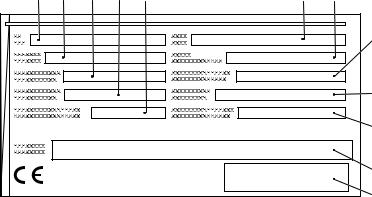
4.1Data plate
34 |
35 |
36 |
37 |
38 |
39 |
40 |
41 |
42
43
44
45
Item |
Description |
Item |
Description |
|
|
|
|
34 |
Type |
40 |
Year of manufacture |
|
|
|
|
35 |
Serial number |
41 |
Load centre (mm) |
|
|
|
|
36 |
Rated capacity (kg) |
42 |
Output |
|
|
|
|
37 |
Battery voltage (V) |
43 |
Min./max. battery weight (kg) |
|
|
|
|
38 |
Net weight w.o. battery (kg) |
44 |
Manufacturer |
|
|
|
|
39 |
Option |
45 |
Manufacturer’s logo |
|
|
|
|
ZFor queries regarding the truck or ordering spare parts always quote the truck serial number (35).
07.10 EN
31
 Loading...