


|
|
EJC B14 / B16 |
09.05 - |
|
|||||
|
|
|
|
|
|
|
|
|
|
|
|
|
|
|
|
|
|
|
|
|
|
Operating instructions |
|
|
|
|
G |
|
|
|
|
50470432 |
|
|
|
|
|
|
|
|
|
03.11 |
|
|
|
|
EJC B14 |
|
|
|
|
|
|
|
|
|
EJC B16 |
|
|
|
|
|
|
|
|
|
|
|
|
|
|
|
|
|
|
|
|
|
|
|
|
|
|
|
|
|
|
|
|
|
|
|
|
|
|
|
|
|
|
|
|
|
|
|
|
|
|
|
|
|
|
|
|
|
|
|
|
|
|
|
|
|
|
|
|
|
|
|
|
|
|
|
|
|
|
|
|
|
|
|
|
|
|
|
|
|
|
|
|
|
|
|
|
|
|
|
|
|
|
|
|
|
|
|
|
|
|
|
|

Declaration of Conformity
Jungheinrich AG, Am Stadtrand 35, D-22047 Hamburg
Manufacturer or his authorized representative in the Community
Type |
Option |
Serial No. |
Year of |
|
|
|
construction |
EJC B14
EJC B16
Additional information
Authorised signatory
Date
GEU Declaration of Conformity
The signatories hereby certify that the specified powered industrial truck conforms to the EU Directive 2006/42/EC (Machine Directive) and 2004/108/EEC (ElectroMagnetic Compatibility, EMC) including their amendments as translated into national legislation of the member countries. The signatories are individually empowered in each case to compile the technical documentation.
03.11 EN
3
4
03.11 EN

03.11 EN
Foreword
Notes on the operating instructions
The present ORIGINAL OPERATING INSTRUCTIONS are designed to provide sufficient instruction for the safe operation of the industrial truck. The information is provided clearly and concisely. The chapters are arranged by letter and the pages are numbered continuously.
The operator manual details different industrial truck models. When operating and servicing the industrial truck, make sure that the particular section applies to your truck model.
Our trucks are subject to ongoing development. Jungheinrich reserves the right to alter the design, equipment and technical features of the system. No guarantee of particular features of the truck should therefore be assumed from the present operating instructions.
Safety notices and text mark-ups
Safety instructions and important explanations are indicated by the following graphics:
DANGER!
Indicates an extremely hazardous situation. Failure to comply with this instruction will result in severe irreparable injury and even death.
WARNING!
Indicates an extremely hazardous situation. Failure to comply with this instruction may result in severe irreparable injury and even death.
CAUTION!
Indicates a hazardous situation. Failure to comply with this instruction may result in slight to medium injury.
NOTE
Indicates a material hazard. Failure to comply with this instruction may result in material damage.
ZUsed before notices and explanations.
t Indicates standard equipment
oIndicates optional equipment
Copyright
Copyright of these operating instructions remains with JUNGHEINRICH AG.
5
Jungheinrich Aktiengesellschaft
Am Stadtrand 35
22047 Hamburg - Germany
Tel: +49 (0) 40/6948-0
www.jungheinrich.com
03.11 EN
6
03.11 EN
Table of Contents |
|
|
A |
Correct Use and Application ................................................... |
9 |
1 |
General.................................................................................................... |
9 |
2 |
Correct application................................................................................... |
9 |
3 |
Approved application conditions.............................................................. |
9 |
4 |
Proprietor responsibilities ........................................................................ |
10 |
5 |
Adding attachments and/or accessories.................................................. |
10 |
B |
Truck Description .................................................................... |
11 |
1 |
Application ............................................................................................... |
11 |
1.1 |
Truck models and rated capacity............................................................. |
11 |
2 |
Assemblies and Functional Description................................................... |
12 |
2.1 |
Assembly Overview ................................................................................. |
12 |
2.2 |
Functional Description ............................................................................. |
14 |
3 |
Technical Specifications .......................................................................... |
15 |
3.1 |
Performance data .................................................................................... |
15 |
3.2 |
Dimensions.............................................................................................. |
16 |
3.3 |
Standard mast version EJC B14 ............................................................. |
17 |
3.4 |
Standard mast version EJC B16 ............................................................. |
17 |
3.5 |
Weights.................................................................................................... |
18 |
3.6 |
Tyre type.................................................................................................. |
18 |
3.7 |
EN norms................................................................................................. |
19 |
3.8 |
Conditions of use..................................................................................... |
20 |
3.9 |
Electrical requirements ............................................................................ |
20 |
4 |
Identification points and data plates ........................................................ |
21 |
4.1 |
Data plate ................................................................................................ |
22 |
4.2 |
Truck load chart....................................................................................... |
23 |
C |
Transport and Commissioning ................................................ |
25 |
1 |
Lifting by crane ........................................................................................ |
25 |
2 |
Transport ................................................................................................. |
26 |
3 |
Using the Truck for the First Time ........................................................... |
27 |
4 |
Adjustment of wheel arms ....................................................................... |
27 |
D |
Battery - Servicing, Recharging, Replacement ....................... |
29 |
1 |
Safety Regulations Governing the Handling of Lead-Acid Batteries ....... |
29 |
2 |
Battery types............................................................................................ |
31 |
3 |
Exposing the battery................................................................................ |
32 |
4 |
Charging the battery ................................................................................ |
33 |
4.1 |
Charging the battery with a stationary charger........................................ |
33 |
5 |
Battery removal and installation .............................................................. |
35 |
7
E |
Operation ................................................................................ |
37 |
1 |
Safety Regulations for the Operation of the Forklift Truck....................... |
37 |
2 |
Displays and Controls.............................................................................. |
38 |
2.1 |
Battery discharge indicator ...................................................................... |
41 |
3 |
Starting up the truck ................................................................................ |
42 |
3.1Checks and operations to be performed before starting daily operation . 42
3.2 |
Preparing the truck for operation ............................................................. |
43 |
3.3 |
Parking the truck securely ....................................................................... |
44 |
3.4 |
Battery discharge monitor........................................................................ |
44 |
4 |
Industrial Truck Operation ....................................................................... |
45 |
4.1 |
Safety regulations for truck operation...................................................... |
45 |
4.2 |
Emergency Disconnect, Travel, Steering, Braking .................................. |
47 |
4.3 |
Lifting, transporting and depositing loads ................................................ |
52 |
5 |
Troubleshooting....................................................................................... |
53 |
5.1 |
Truck does not start................................................................................. |
54 |
5.2 |
Load cannot be lifted ............................................................................... |
54 |
6 |
Operating the truck without its own drive system .................................... |
55 |
7 |
Load handler emergency lowering .......................................................... |
56 |
8 |
Optional equipment ................................................................................. |
57 |
8.1 |
Fork tines................................................................................................. |
57 |
8.2 |
CanCode keypad..................................................................................... |
59 |
8.3 |
CANDIS display instrument ..................................................................... |
63 |
F |
Industrial Truck Maintenance .................................................. |
65 |
1 |
Operational Safety and Environmental Protection................................... |
65 |
2 |
Maintenance Safety Regulations............................................................. |
65 |
3 |
Servicing and Inspection ......................................................................... |
70 |
4 |
Maintenance checklist ............................................................................. |
71 |
5 |
Lubricants and Lubrication Schedule ...................................................... |
74 |
5.1 |
Handling consumables safely.................................................................. |
74 |
5.2 |
Lubrication Schedule ............................................................................... |
76 |
5.3 |
Consumables........................................................................................... |
77 |
6 |
Maintenance and repairs ......................................................................... |
78 |
6.1 |
Preparing the truck for maintenance and repairs .................................... |
78 |
6.2 |
Removing the front panel ........................................................................ |
79 |
6.3 |
Checking the hydraulic oil level ............................................................... |
80 |
6.4 |
Check the gear oil level ........................................................................... |
81 |
6.5 |
Replacing the gauze filter, flushing the gauze filter ................................. |
81 |
6.6 |
Checking electrical fuses......................................................................... |
82 |
6.7 |
Restoring the truck to service after maintenance and repairs ................. |
83 |
7 |
Decommissioning the industrial truck ...................................................... |
84 |
7.1 |
Prior to decommissioning ........................................................................ |
84 |
7.2 |
Action to be taken during decommissioning ............................................ |
86 |
7.3 |
Restoring the truck to service after decommissioning ............................. |
87 |
8 |
Final de-commissioning, disposal............................................................ |
87 |
9 |
Safety tests to be performed at intervals and after unusual incidents ..... |
88 |
03.11 EN
8
|
Appendix |
|
JH Traction Battery Operating Instructions |
Z |
These operating instructions apply only to Jungheinrich battery models. If using |
|
another brand, refer to the manufacturer's operating instructions. |
0506.GB
1
2
0506.GB

A Correct Use and Application
1General
The industrial truck described in the present operating instructions is designed for lifting, lowering and transporting load units.
It must be used, operated and serviced in accordance with the present instructions. Any other type of use is beyond the scope of application and can result in damage to personnel, the industrial truck or property.
2Correct application
NOTE
The maximum load and load distance are indicated on the load chart and must not be exceeded.
The load must rest on the load handler or be lifted by an attachment approved by the manufacturer.
The load must rest on the back of the fork carriage and centrally between the forks.
–Lifting and lowering of loads.
–Transporting lowered loads.
–Do not travel with a raised load (>500 mm).
–Do not carry or lift passengers.
–Do push or pull load units.
3Approved application conditions
–Operation in industrial and commercial environments.
–Permissible temperature range 5°C to 40°C.
–Operation only on secure, level surfaces with sufficient capacity.
–Operation only on routes that are visible and approved by the proprietor.
–Negotiating inclines up to a maximum of 16 %.
–Do not negotiate inclines crosswise or at an angle. Transporting loads downhill.
–Operation in partially public traffic.
ZSpecial equipment and authorisation is required if the truck is to be used in extreme conditions.
The truck is not authorised for use in areas at risk of explosion.
03.11 EN
9
4Proprietor responsibilities
For the purposes of the present operating instructions the “proprietor” is defined as any natural or legal person who either uses the industrial truck himself, or on whose behalf it is used. In special cases (e.g. leasing or renting) the proprietor is considered the person who, in accordance with existing contractual agreements between the owner and user of the industrial truck, is charged with operational duties.
The proprietor must ensure that the industrial truck is used only for the purpose for which it is intended and that there is no danger to life and limb of the user and third parties. Furthermore, accident prevention regulations, safety regulations and operating, servicing and repair guidelines must be followed. The proprietor must ensure that all users have read and understood these operating instructions.
NOTE
Failure to comply with the operating instructions shall invalidate the warranty. The same applies if improper work is carried out on the truck by the customer or third parties without the permission of the manufacturer.
5Adding attachments and/or accessories
Adding accessories
The mounting or installation of additional equipment which affects or enhances the performance of the forklift truck requires the written permission of the manufacturer. Local authority approval may also need to be obtained.
Local authority approval does not however constitute the manufacturer’s approval.
03.11 EN
10
B Truck Description
1Application
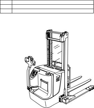
The EJC B14 / B16 is a four wheel, tiller guided electric truck with a steered drive wheel and adjustable wheel arms.
It is designed for use on level floors to lift and transport goods. Open bottom pallets or roll cages can be lifted.
1.1Truck models and rated capacity
The rated capacity depends on the model. The rated capacity can be derived from the model description.
EJCB14
EJC Model name
BSeries
14 Rated capacity x 100 kg
The rated capacity does not generally match the permissible capacity. The capacity can be found on the load chart attached to the rack.
03.11 EN
11

2Assemblies and Functional Description
2.1Assembly Overview
2 |
|
|
1 |
|
|
|
|
3 |
|
3 |
4 |
|
5 |
|
|
|
|
|
|
|
|
|
6 |
7 |
|
|
8 |
|
|
|
|
9, 10 |
|
|
|
|
|
|
11 |
12 |
|
|
13 |
14 |
|
|
|
16 |
|
15 |
|
|
|
|
|
17 |
|
|
18 |
Item |
EJC B14/B16 |
Name |
2 |
t |
Slow travel button |
1 |
t |
Mast |
3 |
t |
Travel switch |
4 |
t |
Mast guard |
|
o |
Mesh for cold store operation |
5 |
t |
Collision safety switch |
6 |
t |
Battery panel |
7 |
t |
Tiller |
8 |
t |
Emergency Disconnect (battery switch) |
|
|
03.11EN |
12
9 |
|
t |
|
Battery charge / discharge unit |
|
|
|
|
|
|
|
o |
|
CANDIS display instrument |
|
|
|
|
|
10 |
|
o |
|
CANCODE keypad |
|
|
|
|
|
11 |
|
o |
|
Load backrest |
|
|
|
|
|
12 |
|
t |
|
Key switch |
|
|
|
|
|
13 |
|
t |
|
Fork tines |
|
|
|
|
|
14 |
|
o |
|
Document storage compartment |
|
|
|
|
|
16 |
|
t |
|
Drive wheel |
|
|
|
|
|
17 |
|
t |
|
Front panel |
|
|
|
|
|
18 |
|
t |
|
Castor wheel |
|
|
|
|
|
|
|
|
|
|
t= Standard equipment |
|
o= Optional equipment |
||
|
|
|
|
|
03.11 EN
13
2.2Functional Description
Safety Mechanisms
–An enclosed, smooth truck geometry with rounded edges ensures safe handling of the truck.
–The wheels are surrounded by a solid skirt.
–Pressing the Emergency Disconnect rapidly cuts out all electrical functions in hazardous situations.
Hydraulic system
–Lifting and lowering are activated via the lift and lower buttons.
–When lifting is activated, the pump unit starts to operate, supplying hydraulic oil from the oil reservoir to the lift cylinder.
–If the truck is fitted with a duplex twin-stage mast (ZZ) or a triplex telescopic mast (DZ) a short, centre-mounted free lift cylinder initially lifts the load carriage (free lift) without changing the overall height of the truck.
Drive system
–A fixed DC motor actuates the drive wheel via a bevel spur gearbox.
–The electronic traction controller ensures smooth drive motor speed control and hence smooth travel, powerful acceleration and electrically controlled braking.
Tiller
–All travel and lift operations can be performed sensitively without having to reach.
–The driver steers with a tiller:
–The drive system can be pivoted +/- 90°.
Electrical system
–24 volt system.
–Electronic traction control is standard.
Controls and Displays
–Ergonomic controls ensure fatigue-free operation for sensitive application of the travel and hydraulic operations.
–The battery discharge indicator shows the available battery capacity.
Mast
–The maximum strength steel sections are narrow, allowing for outstanding fork visibility in particular with the three-stage mast.
–The lift rails and the fork carriage run on permanently-lubricated and hence maintenance-free angled rollers.
Fork tines
– Alternatively, the truck can be fitted with 2A fork tines.
03.11 EN
14
3Technical Specifications
ZTechnical data specified in accordance with VDI 2198. Technical modifications and additions reserved.
3.1Performance data
|
Description |
EJC B14 |
EJC B16 |
|
||
|
|
|
|
|
||
Q |
Rated capacity |
1400 |
1600 |
kg |
||
|
|
|
|
|
|
|
|
Travel speed |
6,0 |
/ 6,0 |
6.0 |
/ 6.0 |
km/h |
|
w / w.o. rated load |
|
|
|
|
|
|
|
|
|
|
|
|
|
Lift speed |
15 |
/ 23 |
14 |
/ 23 |
cm/sec |
|
with / without rated load |
|
|
|
|
|
|
|
|
|
|
|
|
|
Lower speed |
44 |
/ 42 |
40 |
/ 40 |
cm/sec |
|
with / without rated load |
|
|
|
|
|
|
|
|
|
|
||
|
Max. gradeability |
8 / 16 |
7 / 16 |
% |
||
|
w / w.o. rated load |
|
|
|
|
|
|
|
|
|
|
|
|
03.11 EN
15

3.2Dimensions
h4
h3
|
l |
h1 |
|
h5 |
|
||
|
c |
||
|
|
||
h8 |
|
|
|
h2 |
Q |
m2 |
|
|
|
||
s |
20 |
l2 |
|
y |
|||
|
|
||
|
|
l1 |
Ast
b4 |
b5 |
B |
|
|
W |
|
|
a |
03.11 EN
16
|
|
EJC B14 |
EJC B16 |
|
|
|
|
|
|
c |
Load centre distance |
600 |
600 |
mm |
|
|
|
|
|
x |
Load distance |
667 |
667 |
mm |
|
|
|
|
|
y |
Wheelbase |
1409 |
1409 |
mm |
|
|
|
|
|
l1 |
Length with fork length 1150 mm |
2050 |
2050 |
mm |
|
|
|
|
|
l2 |
Fork length |
900 |
900 |
mm |
|
including fork shank |
|
|
|
|
|
|
|
|
b4 |
Dimension between the wheel |
900 - 1350 |
900 - 1350 |
mm |
|
arms (adjustable) |
|
|
|
|
|
|
|
|
b5 |
Width across forks |
316 - 900 |
316 - 900 |
mm |
|
|
|
|
|
m2 |
Ground clearance centre |
30 |
30 |
mm |
|
wheelbase |
|
|
|
|
|
|
|
|
Ast |
Working width 1000x1200 |
2162 |
2162 |
mm |
|
crosswise 1) |
|
|
|
|
|
|
|
|
Ast |
Working aisle width for |
2362 |
2362 |
mm |
|
pallet 800x1200 longit. 1) |
|
|
|
|
|
|
|
|
Wa |
Turning radius |
1629 |
1629 |
mm |
|
lowered / raised |
|
|
|
|
|
|
|
|
1) wit DZ mast: +4 mm |
|
|
|
|
|
|
|
|
|
3.3Standard mast version EJC B14
|
Description |
Telescopic mast |
Twin-reach mast |
Triplex Mast (DZ) |
|
|||
|
(ZT) |
(ZZ) |
|
|
|
|||
|
|
|
|
|
||||
|
|
|
|
|
|
|
|
|
h1 |
Height 1) |
1700 |
- 2600 |
1700 |
- 2600 |
1800 |
- 2250 |
mm |
|
|
|
|
|
|
|
|
|
h2 |
Free lift 2) |
100 |
|
- |
|
- |
mm |
|
|
|
|
|
|
|
|
|
|
h3 |
Lift |
2500 |
- 4300 |
2500 |
- 4300 |
4000 |
- 5350 |
mm |
|
|
|
|
|
|
|
|
|
h4 |
Max. height 4) |
3060 |
- 4860 |
3060 |
- 4860 |
4560 |
- 5910 |
mm |
|
|
|
|
|
|
|
|
|
h5 |
Free lift 3) 5) |
|
- |
1140 - 2040 |
1240 |
- 1690 |
mm |
|
|
|
|
|
|
|
|
|
|
3.4Standard mast version EJC B16
|
Description |
Telescopic mast |
Twin-reach mast |
Triplex Mast (DZ) |
|
|||
|
(ZT) |
(ZZ) |
|
|
|
|||
|
|
|
|
|
||||
|
|
|
|
|
|
|
|
|
h1 |
Height 1) |
1700 |
- 2600 |
1700 |
- 2600 |
1800 |
- 2250 |
mm |
|
|
|
|
|
|
|
|
|
h2 |
Free lift 2) |
100 |
|
- |
|
- |
mm |
|
|
|
|
|
|
|
|
|
|
h3 |
Lift |
2400 |
- 4200 |
2400 |
- 4200 |
3900 |
- 5250 |
mm |
|
|
|
|
|
|
|
|
|
h4 |
Max. height 4) |
2960 |
- 4760 |
2960 |
- 4760 |
4460 |
- 5810 |
mm |
|
|
|
|
|
|
|
|
|
h5 |
Free lift 3) 5) |
|
- |
1140 - 2040 |
1240 |
- 1690 |
mm |
|
|
|
|
|
|
|
|
|
|
03.11 EN
17
3.5Weights
|
|
EJC B14 |
EJC B16 |
|
|
|
|
|
|
|
Net weight excl. battery |
1010 |
1050 |
kg |
|
|
|
|
|
|
Axle load, w. load |
810/1820 |
870/2030 |
kg |
|
front/rear + battery |
|
|
|
|
|
|
|
|
|
Axle load, w.o. load |
830/430 |
840/460 |
kg |
|
front/rear + battery |
|
|
|
|
|
|
|
|
|
Battery weight |
243-297 |
243-297 |
kg |
|
|
|
|
|
3.6Tyre type
|
|
EJC B14 |
EJC B16 |
|
|
|
|
|
|
|
Tyre size, drive |
230x70 |
230x70 |
mm |
|
|
|
|
|
|
Tyre size, load section |
85x75 |
85x75 |
mm |
|
|
|
|
|
|
Castor wheel |
125x50 |
125x50 |
mm |
|
|
|
|
|
|
Wheels, number front/rear |
1x+1/ 4 |
1x+1/ 4 |
|
|
(x = driven) |
|
|
|
|
|
|
|
|
03.11 EN
18

3.7EN norms
Noise emission level
– EJC B14 / B16: 67 dB(A)
in accordance with EN 12053 as harmonised with ISO 4871.
ZThe noise emission level is calculated in accordance with standard procedures and takes into account the noise level when travelling, lifting and when idle. The noise level is measured at the level of the driver's ear.
Electromagnetic compatibility (EMC)
The manufacturer confirms that the truck adheres to the limits for electromagnetic emissions and resistance as well as the static electricity discharge test in accordance with EN 12895 as well as the standardised instructions contained therein.
ZNo changes to electric or electronic components or their arrangement may be made without the written agreement of the manufacturer.
WARNING!
Medical equipment can be damaged by non-ionised radiation
Electrical equipment on the truck emitting non-ionised radiation (e.g. wireless data transmission) can affect operators' medical equipment (pacemakers, hearing aids etc.) and result in malfunctions. Consult with a doctor or the medical equipment manufacturer to clarify whether it can be used near the industrial truck.
03.11 EN
19
3.8Conditions of use
Ambient temperature
– operating at 5°C to 40°C
ZSpecial equipment and authorisation are required if the truck is to be constantly used in conditions of extreme temperature or air humidity fluctuations.
3.9Electrical requirements
The manufacturer certifies compliance with the requirements for the design and manufacture of electrical equipment, according to EN 1175 "Industrial Truck Safety - Electrical Requirements", provided the truck is used according to its purpose.
03.11 EN
20

4Identification points and data plates
19 20
21
21
22
23
24 |
25 |
26 27
V
JU
N
G
H
EI
N
RIC
H
|
Item |
Description |
|
|
|
|
19 |
"Do not reach through the mast" warning |
|
|
|
|
20 |
“Do not step under the load handler” warning |
|
|
|
|
21 |
Attachment points for lifting by crane (with ZZ mast in the middle) |
|
|
|
|
22 |
Truck data plate |
|
|
|
|
23 |
Decal: “No passengers” |
|
|
|
|
25 |
Test plaque |
|
|
|
|
24 |
Capacity |
|
|
|
|
26 |
Serial number |
|
|
|
03.11 EN |
27 |
Model name |
|
|
|
|
|
21

4.1Data plate
28 |
29 |
30 |
31 |
32 |
33 |
34 |
35 |
36
37
38
39
Item |
Description |
Item |
Description |
|
|
|
|
28 |
Type |
34 |
Year of manufacture |
|
|
|
|
29 |
Serial number |
35 |
Load centre (mm) |
|
|
|
|
30 |
Rated capacity (kg) |
36 |
Output |
|
|
|
|
31 |
Battery voltage (V) |
37 |
Min./max. battery weight (kg) |
|
|
|
|
32 |
Net weight w.o. battery (kg) |
38 |
Manufacturer |
|
|
|
|
33 |
Option |
39 |
Manufacturer’s logo |
|
|
|
|
ZFor queries regarding the truck or ordering spare parts always quote the truck serial number (29).
03.11 EN
22

4.2Truck load chart
|
X.XXXX.XX.XX |
40 |
|
|
|
3600 |
1105 |
|
|
600 |
|
The load chart (40) indicates the maximum capacity Q (in kg) for a given load centre D (in mm) and corresponding lift height H (in mm) for the truck with a horizontal load.
Example of calculating the maximum capacity:
With a load centre of gravity distance C of 600 mm and a maximum lift height H of 3600 mm. the max. capacity Q is 1105 kg.
The arrow shaped marks ("41" and "41") on the inner mast and bottom and outer tie bar indicate to the driver when he has exceeded the height limits specified by the capacity plate (21).
41 |
41 |
03.11 EN
23
24
03.11 EN

C Transport and Commissioning
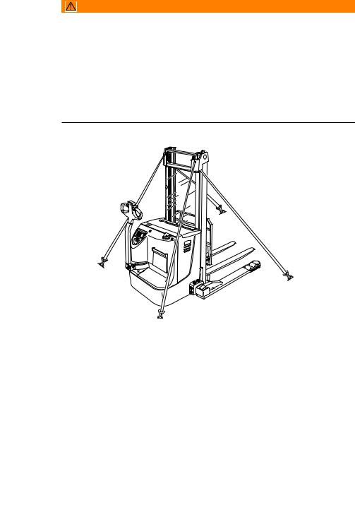
1Lifting by crane
WARNING!
Improper lifting by crane can result in accidents
The use of unsuitable lifting gear can cause the truck to crash when being lifted by crane.
Prevent the truck from striking other objects when it is being raised, and avoid any involuntary movements. If necessary secure the truck with guide ropes.
XThe truck should only be handled by people who are trained in using lifting slings and tools.
XWear safety shoes when lifting the truck by crane. XDo not stand under a swaying load.
XDo not walk into or stand in a hazardous area.
XAlways use lifting gear with sufficient capacity (for truck weight see truck data plate).
XAlways attach the crane slings to the prescribed strap points and prevent them from slipping.
XUse the lifting gear only in the prescribed load direction.
XCrane slings should be fastened in such a way that they do not come into contact with any attachments when lifting.
Lifting the truck by crane |
21 |
Requirements
– Park the truck securely, (see "Parking the truck securely" on page 44).
Tools and Material Required
– Lifting gear
– Crane lifting gear
Procedure
• Secure the lifting slings to the strap points (21).
The truck can now be lifted by crane.
03.11 EN
25
2Transport
WARNING!
Accidental movement during transport
Improper fastening of the truck and mast during transport can result in serious accidents.
XLoading must be carried out by specially trained staff in accordance with recommendations contained in Guidelines VDI 2700 and VDI 2703 In each case correct measurements must be made and appropriate safety measures adopted.
XThe truck must be securely fastened when transported on a lorry or a trailer. XThe lorry / trailer must have fastening rings.
XUse wedges to prevent the truck from moving.
XUse only tension belts or tie-down straps or with sufficient strength.
42
42
Securing the truck for transport
Tools and Material Required
– Tension belts/tie down straps
Procedure
•Move the truck onto the transporting truck.
•Park the truck securely, (see "Parking the truck securely" on page 44).
•Strap the belts (42) around the truck and tension them sufficiently.
The truck can now be transported.
03.11 EN
26

3Using the Truck for the First Time
CAUTION!
Only operate the truck with battery current. Rectified AC current will damage the electronic components. Cable connections to the battery (tow leads) must be less than 6 m long and have a minimum cross-section of 50 mm².
Procedure
•Check the equipment is complete.
•If necessary install the battery, (see "Battery removal and installation" on page 35)
•Charge the battery, (see "Charging the battery" on page 33).
The truck can now be started, (see "Starting up the truck" on page 42)
NOTE
Cold store trucks
XTrucks designed for use in cold stores have a cold store hydraulic oil and a protective frame instead of a mast guard on the mast.
XIf a truck with cold store oil is used outside the cold store, the lowering speeds may increase.
4Adjustment of wheel arms
The distance between the wheel arms is adjustable.
WARNING!
The adjustment of wheel arms must only be performed by a trained service personnel.
03.11 EN
27
28
03.11 EN

D Battery - Servicing, Recharging,
Replacement
1Safety Regulations Governing the Handling of Lead-Acid Batteries
Maintenance personnel
Batteries may only be charged, serviced or replaced by trained personnel. This operator manual and the manufacturer’s instructions concerning batteries and charging stations must be observed when carrying out the work.
Fire protection
Do not smoke and avoid naked flames when handling batteries. Wherever an industrial truck is parked for charging there shall be no inflammable material or lubricants capable of creating sparks within 2 m around the truck. The room must be ventilated. Fire protection equipment must be on hand.
Battery maintenance
The battery cell covers must be kept dry and clean. The terminals and cable shoes must be clean, secure and have a light coating of dielectric grease.
CAUTION!
Before closing the battery panel make sure that the battery cable cannot be damaged. There is a risk of short circuits with damaged cables.
Battery disposal
Batteries may only be disposed of in accordance with national environmental protection regulations or disposal laws. The manufacturer’s disposal instructions must be followed.
03.11 EN
29
 Loading...