


ETM V 110
ETM/V 110/112/114/116
04.99-
Operating instructions
50047421
10.05
G

1
0903.GB
Important notes on transporting and mounting load lifting devices
to reach trucks
Transport
Depending on the overall height of the lifting mast and the local conditions transport
can be performed in three different ways
– Standing, with the lifting mast mounted (for trucks with low overall height)
– Standing, with martially mounted lifting mast tilted towards the overhead guard (for
trucks with medium overall height). Hydraulic line for the lifting function is interrupted.
– Standing, with the lifting mast dismounted (for trucks with large overall height)
Safety Instructions for Assembly and Commissioning
f
The assembly of the truck on site, commissioning the truck and instructing the driver
must be carried out by personnel trained and authorised by the manufacturer
Connect the hydraulic lines to the basic machine / mast interface and commission the
truck only after having installed the mast as per the instructions.
1
0903.GB
Important notes on transporting and mounting load lifting devices
to reach trucks
Transport
Depending on the overall height of the lifting mast and the local conditions transport
can be performed in three different ways
– Standing, with the lifting mast mounted (for trucks with low overall height)
– Standing, with martially mounted lifting mast tilted towards the overhead guard (for
trucks with medium overall height). Hydraulic line for the lifting function is interrup-
ted.
– Standing, with the lifting mast dismounted (for trucks with large overall height)
Safety Instructions for Assembly and Commissioning
f
The assembly of the truck on site, commissioning the truck and instructing the driver
must be carried out by personnel trained and authorised by the manufacturer
Connect the hydraulic lines to the basic machine / mast interface and commission the
truck only after having installed the mast as per the instructions.

0903.GB 20903.GB
2

0108.GB
Foreword
The present ORIGINAL OPERATING INSTRUCTIONS are designed to provide
sufficient instruction for the safe operation of the industrial truck. The information is
provided clearly and concisely. The chapters are arranged by letter. Each chapter
starts with page 1. The page identification consists of a chapter letter and a page
number.
For example: Page B 2 is the second page in chapter B.
The operating instructions detail different truck models. When operating and servicing
the truck, make sure that the instructions apply to your truck model.
Safety instructions and important explanations are indicated by the following
graphics:
f
Used before safety instructions which must be observed to avoid danger to
personnel.
m
Used before notices which must be observed to avoid material damage.
A
Used before notices and explanations.
t Used to indicate standard equipment.
o Used to indicate optional equipment.
Our trucks are subject to ongoing development. Jungheinrich reserves the right to
alter the design, equipment and technical features of the truck. No guarantee of
particular features of the truck should therefore be inferred from the present operating
instructions.
Copyright
Copyright of these operating instructions remains with JUNGHEINRICH AG.
Jungheinrich Aktiengesellschaft
Am Stadtrand 35
22047 Hamburg - GERMANY
Telephone: +49 (0) 40/6948-0
www.jungheinrich.com

0108.GB
0108.GB

I 1
0903.GB
Table of contents
A Correct use and application of the truck
B Description of the truck
1 Application ........................................................................................ B 1
2 Assembly description and functional description ............................ B 2
2.1 Truck ................................................................................................ B 3
2.2 Load lifting system ........................................................................... B 5
3 Technical data - Standard version ................................................... B 6
3.1 Output data for standard truck versions ........................................... B 6
3.2 Standard hoist frame versions ......................................................... B 6
3.3 Dimensions ...................................................................................... B 7
3.4 EN standards ................................................................................... B 8
3.5 Operation conditions ........................................................................ B 8
4 Location of instruction labels and identification plates .................... B 9
4.1 Truck identification plate) ............................................................... B 10
4.2 Load diagram / capacity / load centre / lifting height ...................... B 10
4.3 Load diagram, capacity / load centre / fork .................................... B 11
4.4 Load diagram, capacity / lateral traversing device ......................... B 11
4.5 Pick-up points for lifting jack ........................................................... B 11
C Transportation and commissioning
1 Loading and unloading of trucks by crane ....................................... C 1
2 Commissioning ................................................................................. C 1
3 Moving a defective truck .................................................................. C 2
D Battery - servicing, recharging, replacement
1 Safety regulations governing the handling of lead-acid batteries ..... D 1
2 Battery type ...................................................................................... D 1
3 Exposing the battery ........................................................................ D 2
3.1 Bypassing the drive current interruption ........................................... D 3
3.2 Battery trolley emergency unlocking system .................................... D 3
4 Charging the battery ......................................................................... D 3
5 Removing and installing the battery ................................................. D 4
6 Battery discharge indicator,
battery discharge monitor and hour meter ....................................... D 5

0903.GB
I 2
E Operation
1 Safety regulations governing the operation of the truck ................... E 1
2 Description of the operating controls and indicators ........................ E 2
3 Start-up of truck ................................................................................ E 6
3.1 How to use the safety belt o ............................................................ E 7
4 Truck operation ................................................................................ E 9
4.1 Safety regulations applicable when operating the truck ................... E 9
4.2 Driving, steering, braking ............................................................... E 10
4.3 Adjusting the fork tines ................................................................... E 12
4.4 Picking up and setting down loads ................................................. E 12
4.5 Picking up, lifting and transporting of loads .................................... E 14
4.6 Operating an attachment ................................................................ E 15
4.7 Rendering vehicle safe when parking ............................................ E 15
5 Information and service display (LISA) .......................................... E 16
5.1 LED warning lamps ........................................................................ E 17
5.2 Key assignment .............................................................................. E 17
5.3 Displays .......................................................................................... E 18
5.4 Changing truck parameters ............................................................ E 19
6 Fault locating operations ................................................................ E 20
7 Auxiliary electrical systems ............................................................ E 21
7.1 Seat heating ................................................................................... E 21
7.2 Floodlight ....................................................................................... E 21
7.3 360° warning light .......................................................................... E 22
7.4 Flash lamp ...................................................................................... E 22
7.5 DC/DC transformer on/off switch ................................................... E 22
7.6 Override switch ESA ...................................................................... E 23
7.7 LED Lateral traversing device in centre position ............................ E 23

I 3
0903.GB
F Maintenance of the fork-lift truck
1 Operational safety and environmental protection ..............................F 1
2 Safety regulations applicable to truck maintenance ..........................F 1
3 Servicing and inspection ...................................................................F 3
4 Maintenance Check .........................................................................F 4
5 Lubrication Schedule .........................................................................F 6
5.1 Fuels, coolants and lubricants ...........................................................F 7
5.2 Reservoir filling level ETM/V 110, 112, 114 ......................................F 7
6 Instructions for the servicing operations ............................................F 8
6.1 Preparing the truck for the performance of servicing and
maintenance operations ....................................................................F 8
6.2 Opening the hood ..............................................................................F 8
6.3 Opening the battery doors and the seat hood ...................................F 9
6.4 Checking the hydraulic oil level .........................................................F 9
6.5 Checking the brake fluid level .........................................................F 10
6.6 Safety belt maintenance o .............................................................F 10
6.7 Checking the electric fuses .............................................................F 11
6.8 Recommissioning the truck .............................................................F 12
7 Decommissioning the truck .............................................................F 12
7.1 Operations to be performed prior to decommissioning ...................F 12
7.2 Measures to be taken during decommissioning ..............................F 12
7.3 Recommissioning the truck .............................................................F 13
8 Safety checks to be performed at regular intervals and following
any untoward incidents (D: Accident prevention check
according to BGV D27) ....................................................................F 13

0903.GB
I 4
0903.GB
I 4

A 1
0600.GB
A Correct use and application of the truck
A
The “Guidelines for the Correct Use and Application of Industrial Trucks” (VDMA) are
included in the scope of delivery for this truck. The guidelines are part of these operating instructions and must always be heeded. National regulations are fully applicable.
The fork lift truck described in these operating instructions is a truck that is suitable
for lifting and transporting loads.
It must be used, operated and maintained according to the information in these operating instructions. Any other uses are outside the design envelope and can lead to
injury to persons or damage to equipment and property. Above all, overloading
caused by excessively heavy or unbalanced loads must be avoided. The max. admissible load to be picked up is indicated on the identification plate or load diagram label
shown on the truck. The fork lift truck must not be operated in spaces subject to fire
or explosion hazards, or in spaces where corrosive or very dusty atmospheres prevail.
Duties of the user: A “user” within the meaning of these operating instructions is defined as any natural or legal person who either uses the fork lift truck himself, or on
whose behalf it is used. In special cases (e.g. leasing or renting), the user is considered the person, who, in accordance with existing contractual agreements between the
owner and the user of the fork lift truck, is charged with the observance of the operating duties.
The user must ensure that the truck is not abused and only used within its design limits and that all danger to life and limb of the operator, or third parties, is avoided. In
addition to this, it must be ensured that the relevant accident prevention regulations
and other safety-related provisions, as well as the operating, servicing and maintenance guidelines, are observed. The user must also ensure that all persons operating
the truck have read and understood these operating instructions.
m
If these operating instructions are not observed the warranty becomes void. The
same applies if improper works are carried out at the device by the customer and/or
third parties without permission of our Customer Service.
Mounting of attachments: The mounting or installation of any attachments which
will interfere with, or supplement, the functions of the truck is permitted only after written approval by the manufacturer has been obtained. If necessary, the approval of
local authorities has to be obtained.
Any approval obtained from local authorities does not, however, make the approval
by the manufacturer unnecessary.
A 1
0600.GB
A Correct use and application of the truck
A
The “Guidelines for the Correct Use and Application of Industrial Trucks” (VDMA) are
included in the scope of delivery for this truck. The guidelines are part of these ope-
rating instructions and must always be heeded. National regulations are fully applica-
ble.
The fork lift truck described in these operating instructions is a truck that is suitable
for lifting and transporting loads.
It must be used, operated and maintained according to the information in these ope-
rating instructions. Any other uses are outside the design envelope and can lead to
injury to persons or damage to equipment and property. Above all, overloading
caused by excessively heavy or unbalanced loads must be avoided. The max. admis-
sible load to be picked up is indicated on the identification plate or load diagram label
shown on the truck. The fork lift truck must not be operated in spaces subject to fire
or explosion hazards, or in spaces where corrosive or very dusty atmospheres pre-
vail.
Duties of the user: A “user” within the meaning of these operating instructions is de-
fined as any natural or legal person who either uses the fork lift truck himself, or on
whose behalf it is used. In special cases (e.g. leasing or renting), the user is conside-
red the person, who, in accordance with existing contractual agreements between the
owner and the user of the fork lift truck, is charged with the observance of the opera-
ting duties.
The user must ensure that the truck is not abused and only used within its design li-
mits and that all danger to life and limb of the operator, or third parties, is avoided. In
addition to this, it must be ensured that the relevant accident prevention regulations
and other safety-related provisions, as well as the operating, servicing and mainte-
nance guidelines, are observed. The user must also ensure that all persons operating
the truck have read and understood these operating instructions.
m
If these operating instructions are not observed the warranty becomes void. The
same applies if improper works are carried out at the device by the customer and/or
third parties without permission of our Customer Service.
Mounting of attachments: The mounting or installation of any attachments which
will interfere with, or supplement, the functions of the truck is permitted only after writ-
ten approval by the manufacturer has been obtained. If necessary, the approval of
local authorities has to be obtained.
Any approval obtained from local authorities does not, however, make the approval
by the manufacturer unnecessary.

0600.GB
A 2
0600.GB
A 2
B 1
0903.GB
B Description of the truck
1 Application
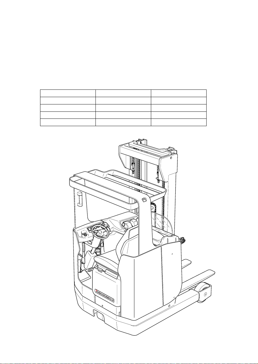
The ETM/V 110-116 is an electrically driven three-wheel truck incorporating a traversing mast and a lateral seat. It is intended for the lifting and transportation of goods
on level ground. It can pick up pallets of open ground support, pallets provided with
lateral boards arranged outside or inside the range of the load-bearing wheels, or trolleys. Loads can be stacked in and out and transported across greater distances.
Its capacity is shown on the identification label.
Type Capacity Load centre distance
ETM/V 110 1000 kg 600 mm
ETM/V 112 1200 kg 600 mm
ETM/V 114 1400 kg 600 mm
ETV 116 1600 kg 600 mm
B 1
0903.GB
B Description of the truck
1 Application
The ETM/V 110-116 is an electrically driven three-wheel truck incorporating a traver-
sing mast and a lateral seat. It is intended for the lifting and transportation of goods
on level ground. It can pick up pallets of open ground support, pallets provided with
lateral boards arranged outside or inside the range of the load-bearing wheels, or trol-
leys. Loads can be stacked in and out and transported across greater distances.
Its capacity is shown on the identification label.
Type Capacity Load centre distance
ETM/V 110 1000 kg 600 mm
ETM/V 112 1200 kg 600 mm
ETM/V 114 1400 kg 600 mm
ETV 116 1600 kg 600 mm
0903.GB
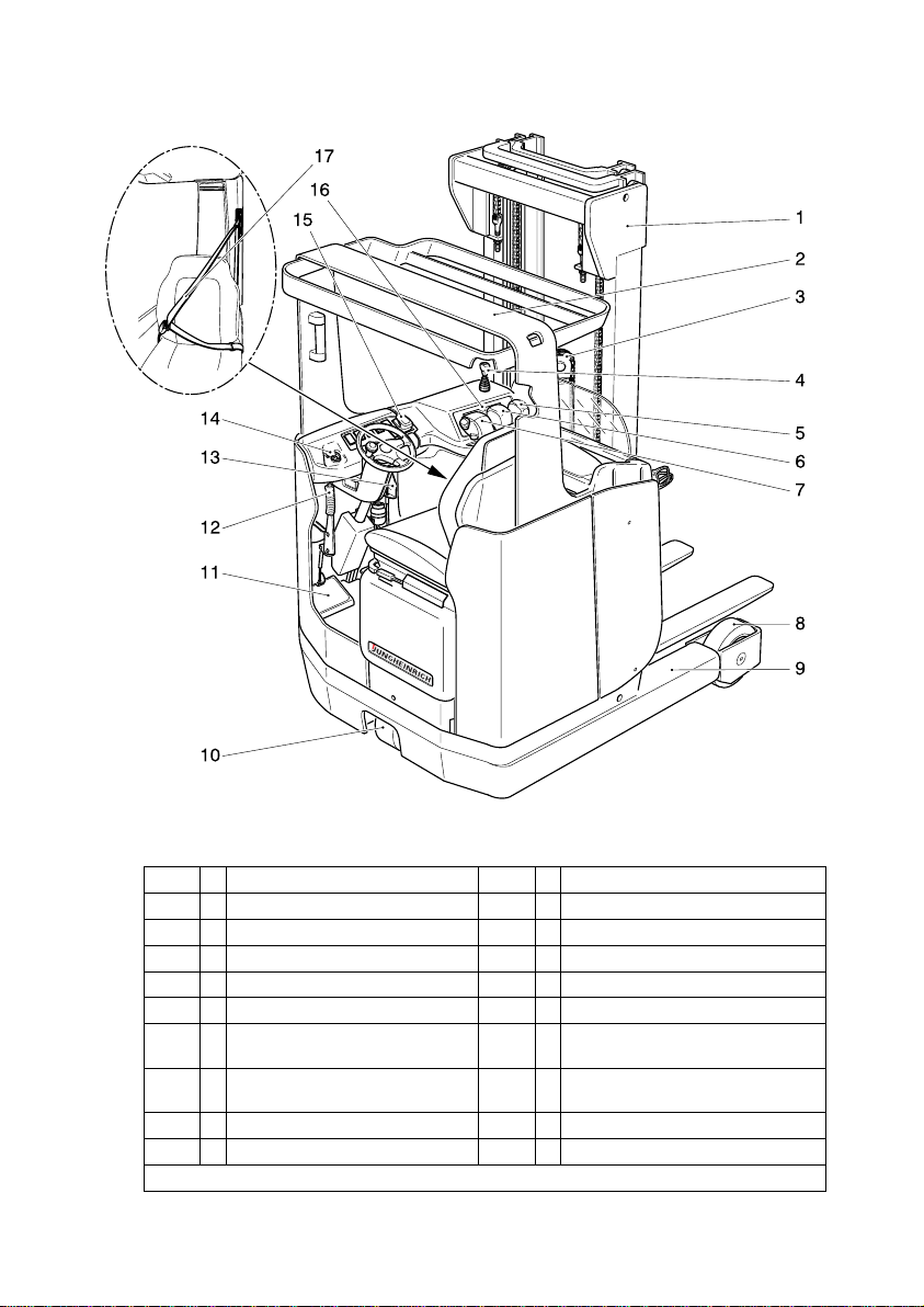
B 2
2 Assembly description and functional description
Item Designation Item Designation
1
t
Clear-view lifting mast 10
t
Drive wheel
2
t
Overhead guard 11
t
Foot switch
3
t
Free-lift cylinder 12
t
Battery trolley unlocking system
4
o
Auxiliary hydraulics (ZH2) 13
t
Parking brake
5
t
Control lever „Mast tilting“ 14
t
Key switch
6
t
Control lever „Traversing of
Mast“
15
t
Master switch (emergency stop)
7
t
Solo-pilot 16
t
Information and
service display (LISA)
8
t
Load-bearing wheels 17
o
Safety belt
9
t
Wheel arm
t
= Standard equipment
o
= Optional equipment
0903.GB
B 2
2 Assembly description and functional description
Item Designation Item Designation
1
t
Clear-view lifting mast 10
t
Drive wheel
2
t
Overhead guard 11
t
Foot switch
3
t
Free-lift cylinder 12
t
Battery trolley unlocking system
4
o
Auxiliary hydraulics (ZH2) 13
t
Parking brake
5
t
Control lever „Mast tilting“ 14
t
Key switch
6
t
Control lever „Traversing of
Mast“
15
t
Master switch (emergency stop)
7
t
Solo-pilot 16
t
Information and
service display (LISA)
8
t
Load-bearing wheels 17
o
Safety belt
9
t
Wheel arm
t
= Standard equipment
o
= Optional equipment

B 3
0903.GB
2.1 Truck
Safety installations: The enclosed truck contour featuring rounded edges ensures
safe handling of the ETM/V 110-116 truck. The driver is protected by the overhead
guard (2). The drive wheel (10) and the load-bearing wheels (8) are enclosed by a
sturdy collision guard.
The master switch (15) ensures instant cut-out of all electrical functions in an emergency. Six red LED warning lights in the information and service display (16) indicate
the following states:
– Direction of motion Forward (V), „Drive direction“
– Parking brake applied
– Direction of motion Backward (R), „Load direction“
– Lack of brake liquid
– Center position of lateral traversing device (option)
– Battery locking
In case of malfunctions within the hydraulic system, line break safety devices limit the
speed at which the load is lowered.
Indicating instruments: Information and service display (LISA) (16) with large indications in LCD-technology. Hour meter and battery discharge indicator with lifting movement cut-out function.
Drive system: The complete drive unit is screwed into the vehicle chassis. A stationary shunt motor with an output of 5.4 kW drives the drive wheel (10) via a spur wheel
gear. The electronic drive current control system provides variable speed to the drive
motor, thus allowing smooth starting without jerks, vigorous accelerating and electronically controlled regenerative braking.
The rate of energy regeneration can be set with the LISA system.
Brake system: Two independent brake systems act on the drive wheel. The service
brake is designed as a hydraulic drum brake with asbestos-free brake linings and is
applied by means of the foot pedal. The parking brake (12) acts mechanically as an
electromagnetic brake on the drum brake by pulling a rope.
The brake fluid level is monitored by the LISA system. A warning light shows when
the parking brake is applied.
Steering system: Chain-operated steering using a steering gear and, as standard,
hydraulic steering. The pivoted drive unit can be swivelled by 90° to both sides. The
steering head can be adjusted hrizontally.
Driver position: The driver’s place is ergonomically designed and equipped with a
large foot space. In order to obtain an ergonomic seating position, the driver can adjust the driver’s seat and the steering column.
Accelerator and brake pedals are arranged as found in normal vehicles.
B 3
0903.GB
2.1 Truck
Safety installations: The enclosed truck contour featuring rounded edges ensures
safe handling of the ETM/V 110-116 truck. The driver is protected by the overhead
guard (2). The drive wheel (10) and the load-bearing wheels (8) are enclosed by a
sturdy collision guard.
The master switch (15) ensures instant cut-out of all electrical functions in an emer-
gency. Six red LED warning lights in the information and service display (16) indicate
the following states:
– Direction of motion Forward (V), „Drive direction“
– Parking brake applied
– Direction of motion Backward (R), „Load direction“
– Lack of brake liquid
– Center position of lateral traversing device (option)
– Battery locking
In case of malfunctions within the hydraulic system, line break safety devices limit the
speed at which the load is lowered.
Indicating instruments: Information and service display (LISA) (16) with large indi-
cations in LCD-technology. Hour meter and battery discharge indicator with lifting mo-
vement cut-out function.
Drive system: The complete drive unit is screwed into the vehicle chassis. A statio-
nary shunt motor with an output of 5.4 kW drives the drive wheel (10) via a spur wheel
gear. The electronic drive current control system provides variable speed to the drive
motor, thus allowing smooth starting without jerks, vigorous accelerating and electro-
nically controlled regenerative braking.
The rate of energy regeneration can be set with the LISA system.
Brake system: Two independent brake systems act on the drive wheel. The service
brake is designed as a hydraulic drum brake with asbestos-free brake linings and is
applied by means of the foot pedal. The parking brake (12) acts mechanically as an
electromagnetic brake on the drum brake by pulling a rope.
The brake fluid level is monitored by the LISA system. A warning light shows when
the parking brake is applied.
Steering system: Chain-operated steering using a steering gear and, as standard,
hydraulic steering. The pivoted drive unit can be swivelled by 90° to both sides. The
steering head can be adjusted hrizontally.
Driver position: The driver’s place is ergonomically designed and equipped with a
large foot space. In order to obtain an ergonomic seating position, the driver can ad-
just the driver’s seat and the steering column.
Accelerator and brake pedals are arranged as found in normal vehicles.
0903.GB
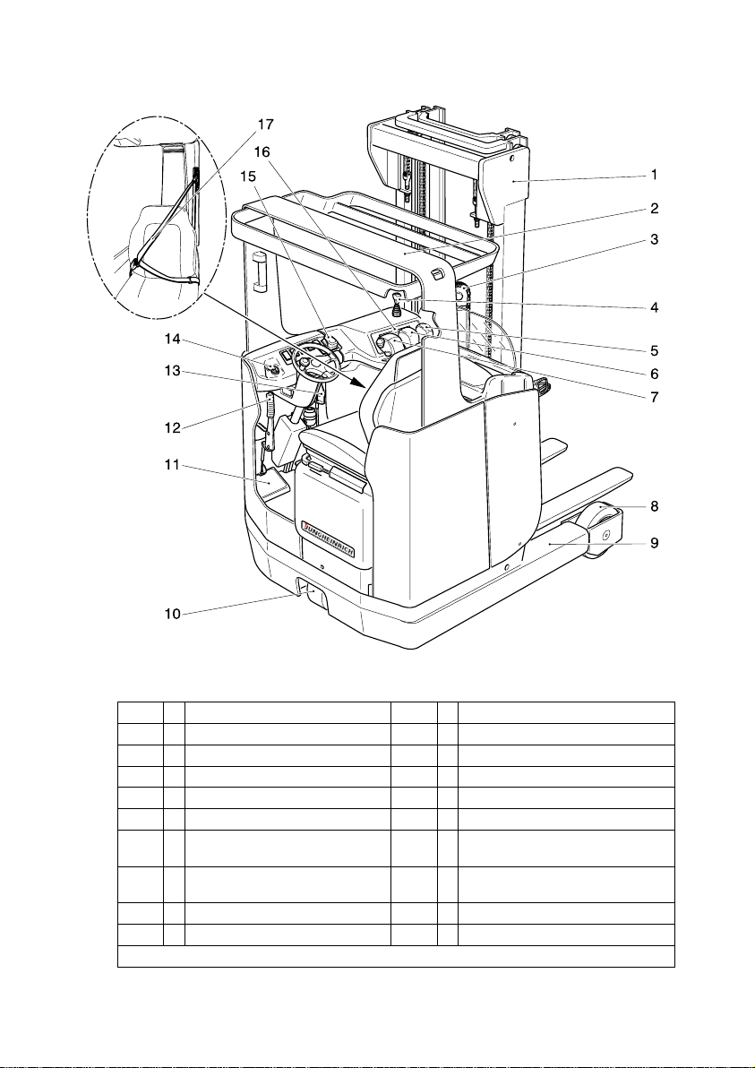
B 4
Item Designation Item Designation
1
t
Clear-view lifting mast 10
t
Drive wheel
2
t
Overhead guard 11
t
Foot switch
3
t
Free-lift cylinder 12
t
Battery trolley unlocking system
4
o
Auxiliary hydraulics (ZH2) 13
t
Parking brake
5
t
Control lever „Mast tilting“ 14
t
Key switch
6
t
Control lever „Traversing of
Mast“
15
t
Master switch (emergency stop)
7
t
Solo-pilot stick 16
t
Information and
service display (LISA)
8
t
Load-bearing wheels 17
o
Safety belt
9
t
Wheel arm
t
= Standard equipment
o
= Optional equipment
0903.GB
B 4
Item Designation Item Designation
1
t
Clear-view lifting mast 10
t
Drive wheel
2
t
Overhead guard 11
t
Foot switch
3
t
Free-lift cylinder 12
t
Battery trolley unlocking system
4
o
Auxiliary hydraulics (ZH2) 13
t
Parking brake
5
t
Control lever „Mast tilting“ 14
t
Key switch
6
t
Control lever „Traversing of
Mast“
15
t
Master switch (emergency stop)
7
t
Solo-pilot stick 16
t
Information and
service display (LISA)
8
t
Load-bearing wheels 17
o
Safety belt
9
t
Wheel arm
t
= Standard equipment
o
= Optional equipment

B 5
0903.GB
Operating controls and indicators: The operating controls and indicators are clearly laid out and arranged at the driver position.
Control lever (5) is used to operate the “Mast tilting” function, control lever (6) to operate the “Forward/backward traversing of mast” function. The solo-pilot stick (7) is
used to operate the “Lifting/lowering” function, to select the direction of travel, to move
the lateral traversing device to the left or right in lateral traversing device operation
(auxiliary hydraulics ZH1) and to actuate the horn.
As an option, an auxiliary hydraulic system (ZH2) can be operated via control lever
(4).
Hydraulic system: Pump unit with an externally ventilated series-wound motor and
a noiseless precision jetting pump. The system is controlled using the individual levers (5-7) and the optional auxiliary hydraulics (4).
Electric system: 48 V two-wire system.
As a standard feature, the truck is equipped with an electronic drive and lifting control
system. The electronic drive control system variably controls the travelling speed and
allows counter-current braking when switching the direction of travel.
The information and service display (LISA) (16) allows a adjustment of the driving and
lifting parameters according to the current requirements. Warning indications, operating error indications and service functions are also shown on the LISA.
For possible drive batteries, see chapter D.
2.2 Load lifting system
Mast holder: The mast holder is borne by supporting rollers. The protracting and re-
tracting movements are carried out directly by a simply telescoping traversing cylinder. The guide rails for the mast holder are screwed onto the wheel arms (9).
Hoist frame: The trucks are equipped with tiltable, telescoping free-vision hoist frames (1) supported by the mast holder. Adjustable lateral rollers and guide pieces absorb the lateral pressure acting on the fork carrier when transporting unbalanced
loads. The mounting of the fork to the fork carrier permits adjustments to be made to
the tines. In the case of the double-lift triplex mast (DZ), the initial lifting sequence of
the load carriage (free lift), which does not change the total height, is effected by a
short free-lift cylinder (3) arranged off-centre. In the case of the telescopic mast (ZT),
the free-lift sequence is limited to 100 mm due to the construction of the truck.
Attachments: Mechanical and hydraulic attachments are available as optional
equipment.
B 5
0903.GB
Operating controls and indicators: The operating controls and indicators are clear-
ly laid out and arranged at the driver position.
Control lever (5) is used to operate the “Mast tilting” function, control lever (6) to ope-
rate the “Forward/backward traversing of mast” function. The solo-pilot stick (7) is
used to operate the “Lifting/lowering” function, to select the direction of travel, to move
the lateral traversing device to the left or right in lateral traversing device operation
(auxiliary hydraulics ZH1) and to actuate the horn.
As an option, an auxiliary hydraulic system (ZH2) can be operated via control lever
(4).
Hydraulic system: Pump unit with an externally ventilated series-wound motor and
a noiseless precision jetting pump. The system is controlled using the individual le-
vers (5-7) and the optional auxiliary hydraulics (4).
Electric system: 48 V two-wire system.
As a standard feature, the truck is equipped with an electronic drive and lifting control
system. The electronic drive control system variably controls the travelling speed and
allows counter-current braking when switching the direction of travel.
The information and service display (LISA) (16) allows a adjustment of the driving and
lifting parameters according to the current requirements. Warning indications, opera-
ting error indications and service functions are also shown on the LISA.
For possible drive batteries, see chapter D.
2.2 Load lifting system
Mast holder: The mast holder is borne by supporting rollers. The protracting and re-
tracting movements are carried out directly by a simply telescoping traversing cylin-
der. The guide rails for the mast holder are screwed onto the wheel arms (9).
Hoist frame: The trucks are equipped with tiltable, telescoping free-vision hoist fra-
mes (1) supported by the mast holder. Adjustable lateral rollers and guide pieces ab-
sorb the lateral pressure acting on the fork carrier when transporting unbalanced
loads. The mounting of the fork to the fork carrier permits adjustments to be made to
the tines. In the case of the double-lift triplex mast (DZ), the initial lifting sequence of
the load carriage (free lift), which does not change the total height, is effected by a
short free-lift cylinder (3) arranged off-centre. In the case of the telescopic mast (ZT),
the free-lift sequence is limited to 100 mm due to the construction of the truck.
Attachments: Mechanical and hydraulic attachments are available as optional
equipment.
0903.GB
B 6
3 Technical data - Standard version
A
Technical data to VDI 2198.
Technical data are subject to alteration and extension in scope.
3.1 Output data for standard truck versions
3.2 Standard hoist frame versions
*) ETM/V 110/112
Designation ETM/V 110 ETM/V 112 ETM/V 114 ETV 116
Q Capacity
(at C = 600 mm)
1000 1200 1400 1600 Kg
C Load centre di-
stance
600 600 600 600 mm
Travelling speed
with / without load
9,4 / 9,9 9,3 / 9,9 9,2 / 9,8 10,3 / 10,6 km/h
Lifting speed
with / without load
0,35 / 0,55 0,34 / 0,55 0,31 / 0,45 0,33 / 0,54 m/s
Lowering speed
with / without load
0,50 0,50 0,50 0,50 m/s
±15%
Traversing speed
with / without load
0,2 0,2 0,2 0,2 m/s
Climbing ability
with / without load
7 / 10 7 / 10 7 / 10 7 / 10 %
Max. climbing ability (max. 5 min)
with / without load
10 / 15 10 / 15 10 / 15 10 / 15 %
Designation Telescopic mast
(ZT)
Double lift triplex
mast (ZZ)*
Double lift
triplex mast (DZ)
h
1
Total height 1950 - 3050 1950 - 2400 1950 - 2900 mm
h
2
Free lift 100 1315 - 1765 1315 - 2256 mm
h
3
Lift 2890 - 5290 2890 - 3790 4250 - 7100 mm
h
4
Max. height 3460 - 5860 3460 - 4360 4894 - 7744 mm
h
2
s
h
2
l
4
l
7
l
1
h
1
h
6
h
3
h
4
Q
c
0903.GB
B 6
3 Technical data - Standard version
A
Technical data to VDI 2198.
Technical data are subject to alteration and extension in scope.
3.1 Output data for standard truck versions
3.2 Standard hoist frame versions
*) ETM/V 110/112
Designation ETM/V 110 ETM/V 112 ETM/V 114 ETV 116
Q Capacity
(at C = 600 mm)
1000 1200 1400 1600 Kg
C Load centre di-
stance
600 600 600 600 mm
Travelling speed
with / without load
9,4 / 9,9 9,3 / 9,9 9,2 / 9,8 10,3 / 10,6 km/h
Lifting speed
with / without load
0,35 / 0,55 0,34 / 0,55 0,31 / 0,45 0,33 / 0,54 m/s
Lowering speed
with / without load
0,50 0,50 0,50 0,50 m/s
±15%
Traversing speed
with / without load
0,2 0,2 0,2 0,2 m/s
Climbing ability
with / without load
7 / 10 7 / 10 7 / 10 7 / 10 %
Max. climbing abili-
ty (max. 5 min)
with / without load
10 / 15 10 / 15 10 / 15 10 / 15 %
Designation Telescopic mast
(ZT)
Double lift triplex
mast (ZZ)*
Double lift
triplex mast (DZ)
h
1
Total height 1950 - 3050 1950 - 2400 1950 - 2900 mm
h
2
Free lift 100 1315 - 1765 1315 - 2256 mm
h
3
Lift 2890 - 5290 2890 - 3790 4250 - 7100 mm
h
4
Max. height 3460 - 5860 3460 - 4360 4894 - 7744 mm
h
2
s
h
2
l
4
l
7
l
1
h
1
h
6
h
3
h
4
Q
c

B 7
0903.GB
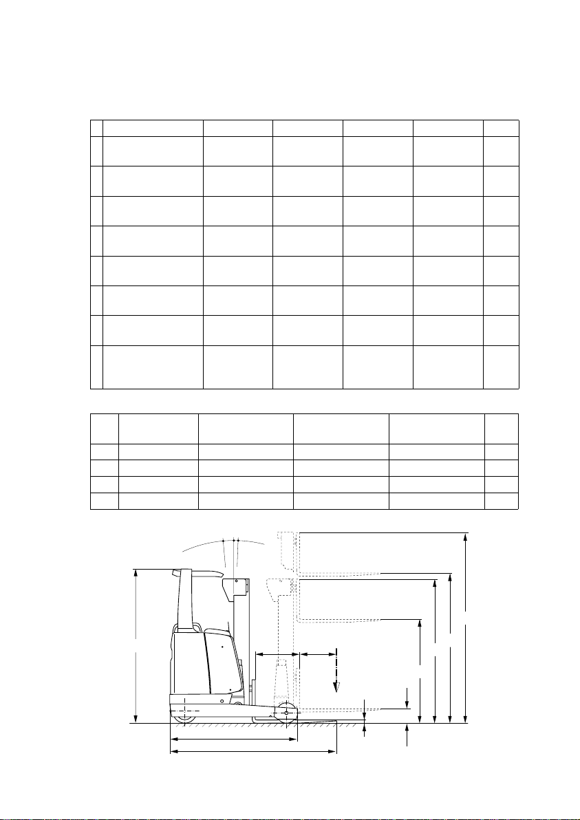
3.3 Dimensions
a) with fork length 800 mm; 330 Ah ±0 mm; 420 Ah battery: +84 mm;
560 Ah battery: +174 mm
b) with fork length 800 mm; 560 Ah battery: +90 mm
c) with fork length 800 mm; 560 Ah battery: +90 mm / 700 Ah battery: +180 mm
d) 420 Ah battery: -84 mm; 560 Ah battery: -174 mm
e) 420 Ah battery: ±0 mm; 560 Ah battery: -90 mm
f) with 280 Ah battery
g) with 420 Ah battery
Designation ETM/V 110
(ZT/DZ/ZZ)
ETM/V112
(ZT/DZ)
ETM/V114
(ZT/DZ)
ETV116
(ZT/DZ)
s Height of lowered
fork
40 40 40 40 mm
h
6
Height above overhead guard
2075 2075 2075 2190 mm
l
1
Total length 1870 a) 1954 b) 1957/1985 b)1967/1995 c)mm
l
4
Traversing distance
602 d) 618 e) 624/602 e) 666/644 e) mm
l
7
Length across
wheel arms
1625 1725 1725 1812 mm
b
1
Total width 1120/1238 1120/1238 1120/1238 - /1238 mm
b
2
Total width ETM/V 1106 1106 1106 1186 mm
W
a
Turning radius 1538 1636 1636 1690 mm
Ast Working aisle
width 800 x 1200
pallets, lengthwise
2508/2606 f) 2590/2690 g) 2592/2614 g)2756/2775 g)mm
Ast Working aisle
width1000 x 1200
pallets, crosswise
2308/2566 f) 2390/2653 g) 2392/2414 g)2716/2731 g)mm
Dead weight : Refer to truck identification plate
Ast
b
1
b
2
Wa
B 7
0903.GB
3.3 Dimensions
a) with fork length 800 mm; 330 Ah ±0 mm; 420 Ah battery: +84 mm;
560 Ah battery: +174 mm
b) with fork length 800 mm; 560 Ah battery: +90 mm
c) with fork length 800 mm; 560 Ah battery: +90 mm / 700 Ah battery: +180 mm
d) 420 Ah battery: -84 mm; 560 Ah battery: -174 mm
e) 420 Ah battery: ±0 mm; 560 Ah battery: -90 mm
f) with 280 Ah battery
g) with 420 Ah battery
Designation ETM/V 110
(ZT/DZ/ZZ)
ETM/V112
(ZT/DZ)
ETM/V114
(ZT/DZ)
ETV116
(ZT/DZ)
s Height of lowered
fork
40 40 40 40 mm
h
6
Height above over-
head guard
2075 2075 2075 2190 mm
l
1
Total length 1870 a) 1954 b) 1957/1985 b)1967/1995 c)mm
l
4
Traversing di-
stance
602 d) 618 e) 624/602 e) 666/644 e) mm
l
7
Length across
wheel arms
1625 1725 1725 1812 mm
b
1
Total width 1120/1238 1120/1238 1120/1238 - /1238 mm
b
2
Total width ETM/V 1106 1106 1106 1186 mm
W
a
Turning radius 1538 1636 1636 1690 mm
Ast Working aisle
width 800 x 1200
pallets, lengthwise
2508/2606 f) 2590/2690 g) 2592/2614 g)2756/2775 g)mm
Ast Working aisle
width1000 x 1200
pallets, crosswise
2308/2566 f) 2390/2653 g) 2392/2414 g)2716/2731 g)mm
Dead weight : Refer to truck identification plate
Ast
b
1
b
2
Wa

0903.GB
B 8
3.4 EN standards
Continuous sound level: 67dB(A)
according to EN 12053 as stipulated in
ISO 4871.
A
The continues sound level is an average value determined according to the standard’s guidelines and takes into consideration the sound level when driving, lifting
and in idle mode. The sound level is measured at the driver’s ear.
Vibration: 0,30 m/s
2
according to document N47E of CEN/TC 150/WG8.
A
The vibration acceleration applied to the operator’s body is measured according the
standard’s guidelines as a linearly integrated, weighted acceleration in vertical direction. The acceleration is measured when driving across bumps at steady speed.
Electromagnetic compatibility (EMC)
The following limit values are observed according to
the product standards “Electromagnetic Compatibility
of Industrial Trucks (9/95)“:
- interference emission (EN 50081-1)
- interference immunity (EN 50082-2)
- electrostatic discharge (EN 61000-4-2).
A
Electrical or electronic components and their arrangement may only be modified after
written approval by the manufacturer has been obtained.
3.5 Operation conditions
Environmental temperature
in operation: –25°C to 40°C
A
If the truck is operated continuously below 0°C, it is recommended to fill the hydraulic
system with frost resisting oil as approved by the manufacturer.
For applications in cold stores resp. in areas with extreme temperature or humidity
changes the truck has to be specially equipped and approved.
0903.GB
B 8
3.4 EN standards
Continuous sound level: 67dB(A)
according to EN 12053 as stipulated in
ISO 4871.
A
The continues sound level is an average value determined according to the stan-
dard’s guidelines and takes into consideration the sound level when driving, lifting
and in idle mode. The sound level is measured at the driver’s ear.
Vibration: 0,30 m/s
2
according to document N47E of CEN/TC 150/WG8.
A
The vibration acceleration applied to the operator’s body is measured according the
standard’s guidelines as a linearly integrated, weighted acceleration in vertical direc-
tion. The acceleration is measured when driving across bumps at steady speed.
Electromagnetic compatibility (EMC)
The following limit values are observed according to
the product standards “Electromagnetic Compatibility
of Industrial Trucks (9/95)“:
- interference emission (EN 50081-1)
- interference immunity (EN 50082-2)
- electrostatic discharge (EN 61000-4-2).
A
Electrical or electronic components and their arrangement may only be modified after
written approval by the manufacturer has been obtained.
3.5 Operation conditions
Environmental temperature
in operation: –25°C to 40°C
A
If the truck is operated continuously below 0°C, it is recommended to fill the hydraulic
system with frost resisting oil as approved by the manufacturer.
For applications in cold stores resp. in areas with extreme temperature or humidity
changes the truck has to be specially equipped and approved.
B 9
0903.GB
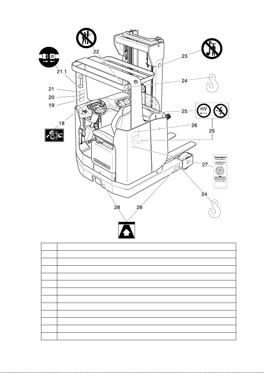
4 Location of instruction labels and identification plates
Item Designation
18 Drive direction when locking the steering wheel (option)
19 Load diagram, capacity / lateral traversing device
20 Load diagram, capacity / load centre / fork
21 Load diagram, capacity / load centre / lifting height
21.1 Sign: Put on safety belt
22 Prohibitive sign “Do not reach through the hoist frame”
23 Prohibitive sign “Keep away from under the load lifting device”
24 Pick-up points for crane transportation
25 Warning sign "Low voltage electronics"
26 Truck identification plate
27 Plaque confirming accident prevention checks (only D)
28 Pick-up points for lifting jack
B 9
0903.GB
4 Location of instruction labels and identification plates
Item Designation
18 Drive direction when locking the steering wheel (option)
19 Load diagram, capacity / lateral traversing device
20 Load diagram, capacity / load centre / fork
21 Load diagram, capacity / load centre / lifting height
21.1 Sign: Put on safety belt
22 Prohibitive sign “Do not reach through the hoist frame”
23 Prohibitive sign “Keep away from under the load lifting device”
24 Pick-up points for crane transportation
25 Warning sign "Low voltage electronics"
26 Truck identification plate
27 Plaque confirming accident prevention checks (only D)
28 Pick-up points for lifting jack
0903.GB
B 10
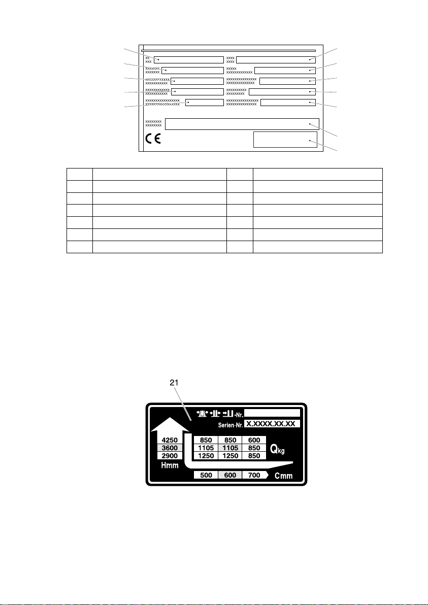
4.1 Truck identification plate)
A
In event of queries relating to the truck or spare part orders, please state the serial
no. (30) of the truck.
4.2 Load diagram / capacity / load centre / lifting height
The load diagram (21) shows the capacity of the truck in Q kg with the hoist frame in
vertical position. The diagram indicates the maximum capacity at a standard load
centre* C (in mm) and at the desired lifting height H (in mm) in the form of a table.
*) Apart from the height of the load, the standard load centre also includes the width
of the load.
Example showing the determination of the max. capacity:
At a load centre C of 600 mm and a max. lifting height H of 3600 mm, the max. capacity Qkg is 1105 kg.
Item Designation Item Designation
29 Type 35 Manufacturer
30 Serial No. 36 Min./max. battery weight in kg
31 Rated capacity in kg 37 Drive power in kW
32 Battery: Voltage V 38 Load centre distance in mm
33 Empty weight without battery in kg 39 Year of manufacture
34 Manufacturer logo 40 Option
35
34
3633
3732
3831
3930
4029
0903.GB
B 10
4.1 Truck identification plate)
A
In event of queries relating to the truck or spare part orders, please state the serial
no. (30) of the truck.
4.2 Load diagram / capacity / load centre / lifting height
The load diagram (21) shows the capacity of the truck in Q kg with the hoist frame in
vertical position. The diagram indicates the maximum capacity at a standard load
centre* C (in mm) and at the desired lifting height H (in mm) in the form of a table.
*) Apart from the height of the load, the standard load centre also includes the width
of the load.
Example showing the determination of the max. capacity:
At a load centre C of 600 mm and a max. lifting height H of 3600 mm, the max. capa-
city Qkg is 1105 kg.
Item Designation Item Designation
29 Type 35 Manufacturer
30 Serial No. 36 Min./max. battery weight in kg
31 Rated capacity in kg 37 Drive power in kW
32 Battery: Voltage V 38 Load centre distance in mm
33 Empty weight without battery in kg 39 Year of manufacture
34 Manufacturer logo 40 Option
35
34
3633
3732
3831
3930
4029
 Loading...