


Interlogix TVT-5610, TVW-5601, TVT-5606, TVT-5607, TVD-5603 Installation Guide
...TruVision Series 6 IP
Camera Installation
Guide
P/N 1073465-EN • REV B • ISS 13DEC18

Copyright
Disclaimer
Trademarks and
patents
Manufacturer
Certification
FCC compliance
© 2018 United Technologies Corporation,
Interlogix is part of UTC Climate, Controls & Security, a unit of United Technologies Corporation. All rights reserved.
Information in this document is subject to change without notice. No part of this document may be reproduced or transmitted in any form or by any means, electronic or mechanical, for any purpose, without the express written permission of UTC Fire & Security Americas Corporation, Inc.
Trade names used in this document may be trademarks or registered trademarks of the manufacturers or vendors of the respective products.
Interlogix
2955 Red Hill Avenue, Costa Mesa, CA 92626-5923, USA
Authorized EU manufacturing representative: UTC Fire & Security B.V.
Kelvinstraat 7, 6003 DH Weert, The Netherlands
Class A: This equipment has been tested and found to comply with the limits for a Class A digital device, pursuant to part 15 of the FCC Rules. These limits are designed to provide reasonable protection against harmful interference when the equipment is operated in a commercial environment. This equipment generates, uses, and can radiate radio frequency energy and, if not installed and used in accordance with the instruction manual, may cause harmful interference to radio communications. Operation of this equipment in a residential area is likely to cause harmful interference in which case the user will be required to correct the interference at his own expense.
FCC conditions
ACMA compliance
Canada
European Union
directives
This device complies with Part 15 of the FCC Rules.
Operation is subject to the following two conditions:
(1)This device may not cause harmful interference.
(2)This Device must accept any interference received, including interference that may cause undesired operation.
Notice! This is a Class A product. In a domestic environment this product may cause radio interference in which case the user may be required to take adequate measures.
This Class A digital apparatus complies with CAN ICES-003 (A)/NMB-3 (A).
Cet appareil numérique de la classe A est conforme à la norme CAN ICES-003 (A)/NMB-3 (A).
This product and - if applicable - the supplied accessories too are marked with "CE" and comply therefore with the applicable harmonized European standards listed under the EMC Directive 2014/30/EU, the RoHS Directive 2011/65/EU.
2012/19/EU (WEEE directive): Products marked with this symbol cannot be disposed of as unsorted municipal waste in the European Union. For proper recycling, return this product to your local supplier upon the purchase of equivalent new equipment, or dispose of it at designated collection points. For more information see: www.recyclethis.info.
2013/56/EU & 2006/66/EC (battery directive): This product contains a battery that cannot be disposed of as unsorted municipal waste in the European Union. See the product documentation for specific battery information. The battery is marked with this symbol, which may include lettering to indicate cadmium (Cd), lead (Pb), or mercury (Hg). For proper recycling, return the battery to your supplier or to a designated collection point. For more information see: www.recyclethis.info.
Installation Guide |
iii |

Product warnings and disclaimers
Contact information and manuals/ tools/ firmware
THESE PRODUCTS ARE INTENDED FOR SALE TO AND INSTALLATION BY QUALIFIED PROFESSIONALS. UTC FIRE & SECURITY CANNOT PROVIDE ANY ASSURANCE THAT ANY PERSON OR ENTITY BUYING ITS PRODUCTS, INCLUDING ANY “AUTHORIZED DEALER” OR “AUTHORIZED RESELLER”, IS PROPERLY TRAINED OR EXPERIENCED TO CORRECTLY INSTALL FIRE AND SECURITY RELATED PRODUCTS.
For more information on warranty disclaimers and product safety information, please check https://firesecurityproducts.com/policy/product-warning/ or scan the QR code:
For contact information and to download the latest manuals, tools, and firmware, go to the web site of your region.
Americas: www.interlogix.com
EMEA: www.firesecurityproducts.com Manuals are available in several languages. Australia/New Zealand: www.utcfs.com.au

Safety instructions
These instructions are intended to ensure that user can use the product correctly to avoid danger or property loss.
The precaution measures are divided into “Warnings” and “Cautions”.
Warnings: Warning messages advise you of hazards that could result in injury or loss of life. They tell you which actions to take or to avoid in order to prevent the injury or loss of life.
Cautions: Caution messages advise you of possible equipment damage. They tell you which actions to take or to avoid in order to prevent damage.
 Warnings
•When using this product, you must comply with the electrical safety regulations of the country and region. Please refer to the technical specifications for detailed information.
•Input voltage should meet both the SELV (Safety Extra Low Voltage) and the Limited Power Source with 24 VAC or 12 VDC according to the IEC60950-1 standard. Please refer to the technical specifications for detailed information.
•Do not connect several devices to one power adapter as adapter overload may cause over-heating or a fire hazard.
Installation Guide |
1 |
•Please make sure that the plug is firmly connected to the power socket. When the device is mounted on a wall or ceiling, it should be firmly fixed to the surface.
•If smoke, odor or noise rises from the device, turn off the power at once and unplug the power cable. Then please contact the service center.
•Proper configuration of all passwords and other security settings is the responsibility of the installer and/or enduser.
 Cautions
•Make sure the power supply voltage is correct before using the camera.
•Do not drop the camera or subject it to physical shock.
•Do not touch sensor modules with fingers. If cleaning is necessary, use clean cloth with a bit of ethanol and wipe it gently. If the camera will not be used for an extended period, please replace the lens cap to protect the sensor from dirt.
•Do not aim the camera at the sun or extra bright places. Blooming or smearing may occur otherwise (which is not a malfunction), and affect the endurance of sensor at the same time.
•The sensor may be burned out by a laser beam, so when any laser equipment is in using, make sure that the surface of sensor will not be exposed to the laser beam.
•Do not place the camera in extremely hot, cold (the operating temperature is-30°C ~+60°C, or -40°C ~ +60°C if the camera model has an “H” in its suffix), dusty or damp locations, and do not expose it to high electromagnetic radiation.
2 |
Installation Guide |
•To avoid heat accumulation, good ventilation is required for operating environment.
•Keep the camera away from liquid while in use.
•During delivery, the camera shall be packed in its original packing, or packing of the same texture.
•Regular part replacement: a few parts (e.g. electrolytic capacitor) of the equipment shall be replaced regularly according to their average enduring time. The average time varies because of differences between operating environment and using history, so regular checking is recommended for all the users. Please contact with your dealer for more details.
•Improper use or replacement of the battery may result in hazard of explosion. Replace with the same or equivalent type only. Dispose of used batteries according to the instructions provided by the battery manufacturer.
•If the product does not work properly, please contact your dealer or the nearest service center. Never attempt to disassemble the camera yourself. (We shall not assume any responsibility for problems caused by unauthorized repair or maintenance.)
Installation Guide |
3 |
Content
Introduction 6
Product overview 6
Contact information and manuals /tools /firmware 8
Installation 9 |
|
|
|
|
Installation environment 10 |
|
|
||
Package contents |
11 |
|
|
|
Cable requirements |
24 |
|
|
|
Camera description |
25 |
|
|
|
Setting up the camera 33 |
|
|
||
IR illuminators |
33 |
|
|
|
Accessing the Micro SD card |
34 |
|
||
Mounting the bullet camera |
34 |
|
||
Mounting the turret camera |
40 |
|
||
Mounting the dome camera |
47 |
|
||
Mounting the wedge camera |
57 |
|
||
Using the protective water resistant connector cover 61 |
||||
Network access |
65 |
|
|
|
Checking your web browser security level |
65 |
|||
Activating the camera 67 |
|
|
||
Using the camera with a TruVision recorder or another |
||||
system 70 |
|
|
|
|
Using the camera with TruVision Navigator |
70 |
|||
Specifications |
71 |
|
|
|
TruVision IP fixed lens bullet cameras 71 |
|
|||
TruVision IP motorized lens bullet cameras |
71 |
|||
4 |
|
|
|
Installation Guide |
TruVision IP fixed lens turret dome 72 |
|
TruVision IP motorized lens turret dome |
73 |
TruVision IP fixed lens dome cameras |
73 |
TruVision IP motorized lens dome cameras 74 TruVision IP fixed lens wedge cameras 75
Pin definitions 76
Installation Guide |
5 |
Introduction
Product overview
This is the installation guide for TruVision Series 6 IP camera models:
TVB-5601 (2MPX IP fixed lens bullet camera)
TVB-5602 (4MPX IP fixed lens bullet camera)
TVB-5603 (8MPX IP fixed lens bullet camera)
TVB-5604 (2MPX IP motorized lens bullet camera)
TVB-5605 (4MPX IP motorized lens bullet camera)
TVB-5606 (8MPX IP motorized lens bullet camera)
TVT-5601 (2MPX IP fixed lens turret camera, gray)
TVT-5602 (2MPX IP fixed lens turret camera, white)
TVT-5603 (2MPX IP fixed lens turret camera, black)
TVT-5604 (4MPX IP fixed lens turret camera, gray)
TVT-5605 (4MPX IP fixed lens turret camera, white)
TVT-5606 (4MPX IP fixed lens turret camera, black)
TVT-5607 (8MPX IP fixed lens turret camera, gray)
TVT-5608 (2MPX IP motorized lens turret camera, gray)
TVT-5609 (4MPX IP motorized lens turret camera, gray)
6 |
Installation Guide |
TVT-5610 (4MPX IP motorized lens turret camera, white)
TVT-5611 (8MPX IP motorized lens turret camera, gray)
TVD-5601 (2MPX IP fixed lens dome camera)
TVD-5602 (4MPX IP fixed lens dome camera)
TVD-5603 (8MPX IP fixed lens dome camera)
TVD-5604 (2MPX IP motorized lens dome camera)
TVD-5605 (4MPX IP motorized lens dome camera)
TVD-5606 (8MPX IP motorized lens dome camera)
TVW-5601 (2MPX IP fixed lens dome camera, 2.0 mm)
TVW-5602 (2MPX IP fixed lens dome camera, gray)
TVW-5603 (2MPX IP fixed lens dome camera, white)
TVW-5604 (2MPX IP fixed lens dome camera, black)
TVW-5605 (4MPX IP fixed lens dome camera, gray)
You can download the software and the following manuals from our web site:
TruVision Series 6 IP Camera Installation Guide
TruVision Series 6 IP Camera Configuration Manual
Installation Guide |
7 |

Contact information and manuals /tools /firmware
For contact information and to download the latest manuals, tools, and firmware, go to the web site of your region:
Americas: www.interlogix.com
EMEA: www.firesecurityproducts.com
Manuals are available in several languages.
Australia/New www.utcfs.com.au
Zealand:
8 |
Installation Guide |
Installation
This section provides information on how to install the cameras.
Before you start:
•Make sure the device in the package is in good condition and all the assembly parts are included.
•The standard power supply is 12 VDC or PoE (802.3 af). Please make sure your power supply matches with your camera.
•Make sure all the related equipment is power-off during the installation.
•Check the specification of the products for the installation environment.
•Make sure that the wall is strong enough to withstand four times the weight of the camera and the bracket.
For the camera that supports IR, you are required to pay attention to the following precautions to prevent IR reflection:
•Dust or grease on the dome cover will cause IR reflection. Please do not remove the dome cover film until the installation is finished. If there is dust or grease on the dome cover, clean the dome cover with clean soft cloth and isopropyl alcohol.
•Make sure that there is no reflective surface too close to the camera lens. The IR light from the camera may reflect back into the lens causing reflection.
•The foam ring around the lens must be seated flush against the inner surface of the bubble to isolate the lens from the IR LEDS. Fasten the dome cover to camera body so that the foam ring and the dome cover are attached seamlessly.
Installation Guide |
9 |
Installation environment
When installing your product, consider these factors:
•Electrical: Install electrical wiring carefully. It should be done by qualified service personnel. Always use a proper
PoE switch or a 12 VDC UL listed Class 2 or CE certified power supply to power the camera. Do not overload the power cord or adapter.
•Ventilation: Ensure that the location planned for the installation of the camera is well ventilated.
•Temperature: Do not operate the camera beyond the specified temperature, humidity or power source ratings. The operating temperature of the camera without heater is between -30 to +60°C (-22 to 140°F). Humidity is below 90%. For the outdoor cameras that feature built-in heaters, the operating temperature range is -40 to 60°C (-40 to140°F)
•Moisture: Do not expose the camera to rain or moisture or try to operate it in wet areas. Turn the power off immediately if the camera is wet and ask a qualified service person for servicing. Moisture can damage the camera and also create the danger of electric shock.
•Servicing: Do not attempt to service this camera yourself. Any attempt to dismantle or remove the covers from this product will invalidate the warranty and may also result in serious injury. Refer all servicing to qualified service personnel.
•Cleaning: Do not touch the sensor modules with fingers. If cleaning is necessary, use a clean cloth with some ethanol and wipe the camera gently. If the camera will not be used for an extended period of time, put on the lens cap to protect the sensors from dirt.
10 |
Installation Guide |
Package contents
Check the package and contents for visible damage. If any components are damaged or missing, do not attempt to use the unit; contact the supplier immediately. If the unit is returned, it must be shipped back in its original packaging.
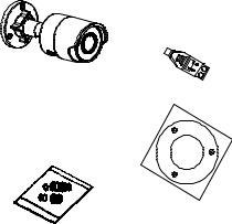
IP fixed lens bullet camera
• |
Camera |
• |
12 VDC connector: |
|
|
|
|
Two terminal |
|
|
|
|
connector with |
|
|
|
|
positive and negative |
|
|
|
|
indicators. |
|
• |
Protective water |
• |
Drill template |
|
|
resistant RJ45 |
|
|
|
|
connector cover: |
|
Hole Ceiling |
|
|
Provides water |
|
Mounting |
|
|
|
|
||
|
resistance to network |
|
|
|
|
|
|
Hole |
|
|
cable connector. |
|
|
|
|
|
|
Hole |
|
Installation Guide |
11 |

• |
Screws |
• |
Torx wrench |
Drywall anchor 7.5 × 24.5 mm (3 pcs)
Screw
M4 × 25 mm (3 pcs)
• |
Installation guide |
• |
Equipment disposal |
|
|
|
sheet |
•Battery disposal sheet
12 |
Installation Guide |
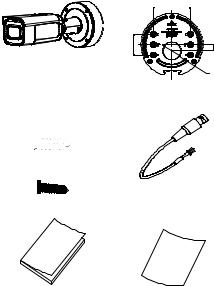
IP motorized lens bullet camera
• Camera |
• |
|
46 mm (1.81 in.) |
Mounting adapter plate
83.5 mm (3.29 in.)
mm 14 ).in 55.(0
40 mm
(1.57 in.)
• |
Screws |
• |
Video test cable |
Drywall anchor 7.5 × 24.5 mm (4 pcs)
Screw
M4 × 25 mm (4 pcs)
• |
Installation guide |
• |
Equipment disposal |
|
|
|
sheet |
Installation Guide |
13 |
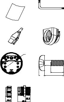
• |
Battery disposal |
• |
Torx wrench |
|
sheet |
|
|
• |
Cable routing tool |
• |
Adapter ring for G3/4 |
• |
Back box |
• |
Screws for the back |
|
|
144.1 mm |
|
box |
|
|
(5.67 in |
|
|
|
|
|
|
|
3.5 mm |
|
|
|
2 mm |
(0.14 in.) |
|
|
|
9 mm(0.35in.) |
|
|
|
|
(0.08 in.) |
|
•G3/4 cable adapter
(mm)
14 |
Installation Guide |
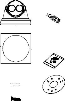
IP fixed lens turret camera
• Camera |
• 12 VDC connector: |
|
Two terminal |
|
connector with |
|
positive and negative |
|
indicators. |
• |
Camera drill template |
• |
Protective water |
|
|
|
resistant RJ45 |
|
|
|
connector cover: |
|
|
|
Provides water |
|
|
|
resistance to |
|
|
|
network cable |
|
|
|
connector. |
• |
Screws |
• |
Adapter plate |
Drywall anchor 7.5 × 24.5 mm (3 pcs)
Screw
M4 × 25 mm (3 pcs)
Installation Guide |
15 |

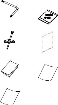
•Torx wrench
•Screw PM6-32 × 10 (4 pcs, used to attach
the turret camera to a 2 Gang electrical box)
•Installation guide
•Equipment disposal sheet
•Screw PM4 × 8 (3pcs)
•Screw KM4 × 8 (4 pcs, used to
attach the adapter to the brackets)
•Installation guide of the turret adapter
•Battery disposal sheet
16 |
Installation Guide |

IP motorized lens turret camera
• Camera |
• Mounting adapter plate |
|
|
83.5 mm (3.29 in.) |
36 mm |
|
|
|
|
|
(1.42 in.) |
).in 81.(1 mm 46
• |
Screws |
• |
Torx wrench |
Drywall anchor 7.5 × 24.5 mm (4 pcs)
Screw
M4 × 25 mm (4 pcs)
• |
Installation |
• |
Battery disposal sheet |
|
guide |
|
|
Installation Guide |
17 |
•Equipment disposal sheet
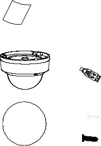
IP fixed lens dome camera
•Camera
•Camera drill template
18
•12 VDC connector: Two terminal connector with positive and negative indicators.
•Screws
Drywall anchor 7.5 × 24.5 mm (3 pcs)
Screw
M4 × 25 mm (3 pcs)
Installation Guide
• |
Torx wrench |
• |
Water joint: Provides |
|
|
|
water resistance to |
|
|
|
network cable |
|
|
|
connector. |
• |
Toggle bolt (3 pcs) |
• |
Gray cloth |
• |
Installation guide |
• |
Equipment disposal |
|
|
|
sheet |
•Battery disposal sheet
Installation Guide |
19 |

IP motorized lens dome camera
• Camera |
• Mounting adapter plate |
|
46 mm (1.81 in.) |
|
45 mm |
mm (3.29 in.) |
(1.77 in.) |
140 mm |
|
83.5 |
(5.51 in.) |
|
|
|
31.5 mm (1.24 in.) |
• |
Video test cable |
• |
Screws |
Drywall anchor 7.5 × 24.5 mm (4 pcs)
Screw
M4 × 25 mm (4 pcs)
• |
Torx wrench |
• |
Cable routing tool |
|||
|
|
|
|
|
|
|
|
|
|
|
|
|
|
|
|
|
|
|
|
|
|
|
|
|
|
|
|
20 |
Installation Guide |
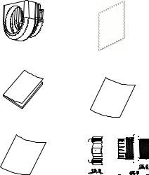
• |
Adapter ring for G3/4 |
• |
Gray cloth |
• |
Installation guide |
• |
Equipment disposal |
|
|
|
sheet |
• |
Battery disposal sheet |
• |
G3/4 cable adapter |
|
||||||||||||||
|
|
|
|
|
|
|
|
|
|
|
|
|
|
|
|
|
|
|
|
|
|
|
|
|
|
|
|
|
|
|
|
|
|
|
|
|
|
|
|
|
|
|
|
|
|
|
|
|
|
|
|
|
|
|
|
|
|
|
|
|
|
|
|
|
|
|
|
|
|
|
|
|
|
|
|
|
|
|
|
|
|
|
|
|
|
|
|
|
|
|
|
|
|
|
|
|
|
|
|
|
|
|
|
|
|
|
|
|
|
|
|
|
|
|
|
|
|
|
|
|
|
|
|
|
|
|
|
|
|
|
|
|
|
|
|
|
|
|
|
|
|
|
|
|
|
|
|
|
|
|
|
|
|
|
|
|
|
|
|
|
|
|
|
|
|
|
|
|
|
|
(mm)
Installation Guide |
21 |

IP fixed lens wedge camera
• Camera |
• 12 VDC connector: |
|
Two terminal connector |
|
with positive and |
|
negative indicators. |
•Screws
Drywall anchor 7.5 × 24.5 mm (3 pcs)
Screw
M4 × 25 mm (3 pcs)
•Screws: M4 × 8 (3 pcs) Used for mounting the wedge to the adapter plate
• |
Adapter plate |
• |
Protective water |
|
|
|
resistant RJ45 |
|
|
|
connector cover: |
|
|
|
Provides water |
|
|
|
resistance to network |
|
|
|
cable connector. |
22 |
Installation Guide |
 Loading...