

Page 1
OPERATING MANUAL
XTC/C
XTC/C XTC/2
Thin Film Deposition Controller
IPN 074-183
XTC/2
Page 2

Page 3

OPERATING MANUAL
XTC/C XTC/2
Thin Film Deposition Controller
IPN 074-183X
TWO TECHNOLOGY PLACE
EAST SYRACUSE, NY 13057-9714 USA
Phone: +315.434.1100
Fax: +315.437.3803
Email: reachus@inficon.com
VISIT US ON THE WEB AT www.inficon.com
©2001 INFICON 092304
ALTE LANDSTRASSE 6
LI-9496 BALZERS, LIECHTENSTEIN
Phone: +423.388.3111
Fax: +423.388.3700
Email: reach.liechtenstein@ inficon.com
BONNER STRASSE 498
D-50968 COLOGNE, GERMANY
Phone: +49.221.347.40
Fax: +49.221.347.41429
Email: reach.germany@i nficon.com
Page 4

Trademarks
The trademarks of the products mentioned in this manual are held by the companies that
produce them.
INFICON®, CrystalSix® are trademarks of INFICON Inc.
All other brand and product names are trademarks or registered trademarks of their respective companies.
The information contained in this manual is believed to be accurate and reliable. However, INFICON assumes
no responsibility for its use and shall not be liable for any special, incidental, or consequential damages related
to the use of this product.
©2001 All rights reserved.
Reproduction or adaptation of any part of this document without permission is unlawful.
Page 5

DECLARATION
OF
CONFORMITY
This is to certify that this equipment, designed and manufactured by:
INFICON Inc.
2 Technology Place
East Syracuse, NY 13057
USA
meets the essential safety requirements of the European Union and is placed on the
market accordingly. It has been constructed in accordance with good engineering
practice in safety matters in force in the Community and does not endanger the safety
of persons, domestic animals or property when properly installed and maintained and
used in applications for which it was made.
Equipment Description: XTC/2 and XTC/C Deposition Controllers, including _
the Oscillator Package and Crystal Sensor as properly
installed. ________
Applicable Directives: 73/23/EEC as amended by 93/68/EEC
89/336/EEC as amended by 93/68/EEC
Applicable Standards: EN 61010-1 : 1993, Fixed Equipment
EN 55011, Group 1, Class A : 1991
EN 50082-2 : 1995 ____ ______
CE Implementation Date: January 3, 1995
Revised to include EMC Directive: January 2, 1997
Authorized Representative: Gary W. Lewis
Vice President – Quality Assurance
INFICON Inc.
ANY QUESTIONS RELATIVE TO THIS DECLARATION OR TO THE SAFETY OF LEYBOLD INFICON'S PRODUCTS SHOULD
BE DIRECTED, IN WRITING, TO THE QUALITY ASSURANCE DEPARTMENT AT THE ABOVE ADDRESS.
04/15/97
Page 6

Page 7

Registration Card
Thank you for selecting INFICON instrumentation.
®
Please fill out and return this postage paid card as soon as possible.
Model
Serial #
Name
Title
Company
Address
City
Country
State Zip
Fax# Email
Bldg./MS
Phone #
Your help is very important in our continuing efforts to improve our manuals.
Using the table below, please circle the appropriate rank for each aspect.
In the Importance column, please indicate the importance of each aspect.
Manual Title
Very
VD
VD
074-
Dissatisfied
D
D
No
Opinion
NO
NO
Satisfied
S
S
Very
Satisfied
VS
VS
(ranked from
1 to 5, where
1 is low and
Part # (see Title Page)
Aspect
Found everything
I needed
Easy to read
Dissatisfied
Importance
5 is high)
Easy to use
Relevant to
my work
Accurate
information
Well-written
Well-organized
Technical Enough
Helped me
solve problems
VD
VD
VD
VD
VD
VD
VD
D
D
D
D
D
D
D
NO
NO
NO
NO
NO
NO
NO
S
S
S
S
S
S
If you have additional comments, please contact INFICON.
TWO TECHNOLOGY PLACE
EAST SYRACUSE, NY 13057-9714 USA
Phone: +315.434.1100
Fax: +315.437.3803
Email: reachus@inficon.com
VISIT US ON THE WEB AT www.inficon.com
ALTE LANDSTRASSE 6
LI-9496 BALZERS, LIECHTEN STEIN
Phone: +423.388.3111
Fax: +423.388.3700
Email: reach.liechtenstein@inficon.com
VS
S
VS
VS
VS
VS
VS
VS
®
BONNER STRASSE 498
D-50968 COLOGNE, GERMANY
Phone: +49.221.347.40
Fax: +49.221.347.41429
Email: reach.germany@inficon.com
Page 8

BUSINESS REPLY MAIL
FIRST CLASS PERMIT NO. 49 EAST SYRACUSE, NEW YORK
POSTAGE WILL BE PAID BY ADDRESSEE
INFICON INC.
Two Technology P lace
East Syracuse, New York 13057-9714
Page 9

Warranty
WARRANTY AND LIABILITY - LIMITATION: Seller warrants the products
manufactured by it, or by an affiliated company and sold by it, and described on
the reverse hereof, to be, for the period of warranty coverage specified below, free
from defects of materials or workmanship under normal proper use and service.
The period of warranty coverage is specified for the respective products in the
respective Seller instruction manuals for those products but shall in no event
exceed one (1) year from the date of shipment thereof by Seller. Seller's liability
under this warranty is limited to such of the above products or parts thereof as are
returned, transportation prepaid, to Seller's plant, not later than thirty (30) days
after the expiration of the period of warranty coverage in respect thereof and are
found by Seller's examination to have failed to function properly because of
defective workmanship or materials and not because of improper installation or
misuse and is limited to, at Seller's election, either (a) repairing and returning the
product or part thereof, or (b) furnishing a replacement product or part thereof,
transportation prepaid by Seller in either case. In the event Buyer discovers or
learns that a product does not conform to warranty, Buyer shall immediately notify
Seller in writing of such non-conformity, specifying in reasonable detail the nature
of such non-conformity. If Seller is not provided with such written notification,
Seller shall not be liable for any further damages which could have been avoided if
Seller had been provided with immediate written notification.
THIS WARRANTY IS MADE AND ACCEPTED IN LIEU OF ALL OTHER
WARRANTIES, EXPRESS OR IMPLIED, WHETHER OF MERCHANTABILITY OR
OF FITNESS FOR A PARTICULAR PURPOSE OR OTHERWISE, AS BUYER'S
EXCLUSIVE REMEDY FOR ANY DEFECTS IN THE PRODUCTS TO BE SOLD
HEREUNDER. All other obligations and liabilities of Seller, whether in contract or
tort (including negligence) or otherwise, are expressly EXCLUDED. In no event
shall Seller be liable for any costs, expenses or damages, whether direct or
indirect, special, incidental, consequential, or other, on any claim of any defective
product, in excess of the price paid by Buyer for the product plus return
transportation charges prepaid.
No warranty is made by Seller of any Seller product which has been installed,
used or operated contrary to Seller's written instruction manual or which has been
subjected to misuse, negligence or accident or has been repaired or altered by
anyone other than Seller or which has been used in a manner or for a purpose for
which the Seller product was not designed nor against any defects due to plans or
instructions supplied to Seller by or for Buyer.
This manual is intended for private use by INFICON® Inc. and its customers.
Contact INFICON before reproducing its contents.
NOTE: These instructions do not provide for every contingency that may arise in
connection with the installation, operation or maintenance of this equipment.
Should you require further assistance, please contact INFICON.
TWO TECHNOLOGY PLACE
EAST SYRACUSE, NY 13057-9714 USA
Phone: +315.434.1100
Fax: +315.437.3803
Email: reachus@inficon.com
VISIT US ON THE WEB AT www.inficon.com
ALTE LANDSTRASSE 6
LI-9496 BALZERS, LIECHTEN STEIN
Phone: +423.388.3111
Fax: +423.388.3700
Email: reach.liechtenstein@inficon.com
BONNER STRASSE 498
D-50968 COLOGNE, GERMANY
Phone: +49.221.347.40
Fax: +49.221.347.41429
Email: reach.germany@inficon.com
Page 10

Page 11

XTC/C - XTC/2 Operating Manual
Table Of Contents
Chapter 1
Introduction and Specifications
1.1 Instrument Safety . . . . . . . . . . . . . . . . . . . . . . . . . . . . . . . . . . . . . . . . .1-1
1.1.1 Notes, Cautions, Warnings . . . . . . . . . . . . . . . . . . . . . . . . . . . . . . . . . .1-1
1.1.2 General Safety Information . . . . . . . . . . . . . . . . . . . . . . . . . . . . . . . . . .1-2
1.1.3 Earth Ground. . . . . . . . . . . . . . . . . . . . . . . . . . . . . . . . . . . . . . . . . . . . .1-3
1.1.4 Main Power Connection . . . . . . . . . . . . . . . . . . . . . . . . . . . . . . . . . . . .1-4
1.2 Introduction to the Instrument . . . . . . . . . . . . . . . . . . . . . . . . . . . . . . . .1-5
1.3 Specifications . . . . . . . . . . . . . . . . . . . . . . . . . . . . . . . . . . . . . . . . . . . . 1-6
1.3.1 Specifications XTC/2 and XTC/C . . . . . . . . . . . . . . . . . . . . . . . . . . . . . .1-6
1.3.1.1 General. . . . . . . . . . . . . . . . . . . . . . . . . . . . . . . . . . . . . . . . . . . . . . . . .1-6
1.3.1.2 Measurement . . . . . . . . . . . . . . . . . . . . . . . . . . . . . . . . . . . . . . . . . . . . 1-6
1.3.1.3 Source Controls . . . . . . . . . . . . . . . . . . . . . . . . . . . . . . . . . . . . . . . . . .1-6
1.3.1.4 Input/Output . . . . . . . . . . . . . . . . . . . . . . . . . . . . . . . . . . . . . . . . . . . . .1-7
1.3.1.5 Recorder Output . . . . . . . . . . . . . . . . . . . . . . . . . . . . . . . . . . . . . . . . . . 1-7
1.3.1.6 Display . . . . . . . . . . . . . . . . . . . . . . . . . . . . . . . . . . . . . . . . . . . . . . . . .1-7
1.3.1.7 Process Recipe Storage . . . . . . . . . . . . . . . . . . . . . . . . . . . . . . . . . . . .1-7
1.3.1.8 Hardware interface . . . . . . . . . . . . . . . . . . . . . . . . . . . . . . . . . . . . . . . .1-8
1.3.1.9 Operation . . . . . . . . . . . . . . . . . . . . . . . . . . . . . . . . . . . . . . . . . . . . . . .1-8
1.3.2 Transducer Specifications (optional) . . . . . . . . . . . . . . . . . . . . . . . . . . .1-9
1.3.3 XIU (Crystal Interface Unit) Specifications . . . . . . . . . . . . . . . . . . . . . . . 1-9
1.4 Guide to the Use of the Manual. . . . . . . . . . . . . . . . . . . . . . . . . . . . . .1-10
1.5 XTC/C Users and Installers Note. . . . . . . . . . . . . . . . . . . . . . . . . . . . .1-10
1.6 Related Manuals . . . . . . . . . . . . . . . . . . . . . . . . . . . . . . . . . . . . . . . . .1-11
1.7 How To Contact Customer Support. . . . . . . . . . . . . . . . . . . . . . . . . . . 1-11
IPN 074-183X
1.7.1 Application Support. . . . . . . . . . . . . . . . . . . . . . . . . . . . . . . . . . . . . . .1-11
1.7.2 Field Service and Repair Support . . . . . . . . . . . . . . . . . . . . . . . . . . . .1-12
1.7.3 Returning Your Instrument . . . . . . . . . . . . . . . . . . . . . . . . . . . . . . . . .1-12
Chapter 2
Quick Use Guide
2.1 Unpacking, Initial Inspection and Inventory . . . . . . . . . . . . . . . . . . . . . .2-1
2.1.1 Unpacking and Inspection Procedures . . . . . . . . . . . . . . . . . . . . . . . . .2-1
2.1.2 Inventory. . . . . . . . . . . . . . . . . . . . . . . . . . . . . . . . . . . . . . . . . . . . . . . . 2-1
2.1.2.1 XTC/2 System Configuration. . . . . . . . . . . . . . . . . . . . . . . . . . . . . . . . .2-2
2.1.2.2 XTC/C System Configuration. . . . . . . . . . . . . . . . . . . . . . . . . . . . . . . . .2-2
TOC - 1
Page 12

XTC/C - XTC/2 Operating Manual
2.1.2.3 Ship Kit - XTC/2 XTC/C . . . . . . . . . . . . . . . . . . . . . . . . . . . . . . . . . . . . 2-3
2.2 Voltage Selection . . . . . . . . . . . . . . . . . . . . . . . . . . . . . . . . . . . . . . . . . 2-4
2.3 Installation Guide and Schematic . . . . . . . . . . . . . . . . . . . . . . . . . . . . . 2-8
2.4 XTC/2 Front Panel Description. . . . . . . . . . . . . . . . . . . . . . . . . . . . . . 2-10
2.4.1 XTC/2 Front Control Panel Description. . . . . . . . . . . . . . . . . . . . . . . . 2-10
2.4.2 XTC/2 Display Description . . . . . . . . . . . . . . . . . . . . . . . . . . . . . . . . . 2-12
2.5 XTC/C Front Panel Description . . . . . . . . . . . . . . . . . . . . . . . . . . . . . 2-16
2.6 Rear Panel Description . . . . . . . . . . . . . . . . . . . . . . . . . . . . . . . . . . . 2-18
2.6.1 Power Module . . . . . . . . . . . . . . . . . . . . . . . . . . . . . . . . . . . . . . . . . . 2-18
2.6.2 Configuration Switches 1 & 2 . . . . . . . . . . . . . . . . . . . . . . . . . . . . . . . 2-19
2.6.3 Grounding Stud . . . . . . . . . . . . . . . . . . . . . . . . . . . . . . . . . . . . . . . . . 2-22
2.6.4 System I/O . . . . . . . . . . . . . . . . . . . . . . . . . . . . . . . . . . . . . . . . . . . . . 2-23
2.6.5 AUX I/O . . . . . . . . . . . . . . . . . . . . . . . . . . . . . . . . . . . . . . . . . . . . . . . 2-24
2.6.6 Sensor 1, Sensor 2. . . . . . . . . . . . . . . . . . . . . . . . . . . . . . . . . . . . . . . 2-25
2.6.7 RS232 . . . . . . . . . . . . . . . . . . . . . . . . . . . . . . . . . . . . . . . . . . . . . . . . 2-26
2.6.8 Communication Option. . . . . . . . . . . . . . . . . . . . . . . . . . . . . . . . . . . . 2-27
2.6.9 Source 1,2 . . . . . . . . . . . . . . . . . . . . . . . . . . . . . . . . . . . . . . . . . . . . . 2-27
2.6.10 Manufacturer’s Identific ation and
Serial Number Plate. . . . . . . . . . . . . . . . . . . . . . . . . . . . . . . . . . . . . . 2-28
2.6.11 Recorder . . . . . . . . . . . . . . . . . . . . . . . . . . . . . . . . . . . . . . . . . . . . . . 2-28
2.7 Operation as a Deposition Monitor . . . . . . . . . . . . . . . . . . . . . . . . . . . 2-29
2.7.1 Monitoring - Systems Without a Source Shutter . . . . . . . . . . . . . . . . . 2-29
2.7.2 Monitoring - Systems with a Source Shutter. . . . . . . . . . . . . . . . . . . . 2-30
2.7.3 Rate Sampling . . . . . . . . . . . . . . . . . . . . . . . . . . . . . . . . . . . . . . . . . . 2-31
2.7.4 Nontraditional Applications. . . . . . . . . . . . . . . . . . . . . . . . . . . . . . . . . 2-32
2.7.4.1 Etching. . . . . . . . . . . . . . . . . . . . . . . . . . . . . . . . . . . . . . . . . . . . . . . . 2-32
2.7.4.2 Immersion in Liquids . . . . . . . . . . . . . . . . . . . . . . . . . . . . . . . . . . . . . 2-32
2.7.4.3 Biological . . . . . . . . . . . . . . . . . . . . . . . . . . . . . . . . . . . . . . . . . . . . . . 2-32
2.7.4.4 Measurement of Liquids. . . . . . . . . . . . . . . . . . . . . . . . . . . . . . . . . . . 2-33
TOC - 2
2.8 Operation as a One Layer Controller . . . . . . . . . . . . . . . . . . . . . . . . . 2-33
IPN 074-183X
2.8.1 Skipping a State Overview . . . . . . . . . . . . . . . . . . . . . . . . . . . . . . . . . 2-34
2.8.2 Idle State Processing Overview . . . . . . . . . . . . . . . . . . . . . . . . . . . . . 2-34
2.8.3 Manual Power Overview . . . . . . . . . . . . . . . . . . . . . . . . . . . . . . . . . . . 2-34
2.8.4 Time Power State Overview. . . . . . . . . . . . . . . . . . . . . . . . . . . . . . . . 2-35
2.8.5 Controlling the Source Overview . . . . . . . . . . . . . . . . . . . . . . . . . . . . 2-35
2.9 Operation as a Multi-Layer Controller. . . . . . . . . . . . . . . . . . . . . . . . . 2-36
2.9.1 Defining a Process Overview . . . . . . . . . . . . . . . . . . . . . . . . . . . . . . . 2-36
Page 13

XTC/C - XTC/2 Operating Manual
Chapter 3
Installation
3.1 Installing the Instrument - Details . . . . . . . . . . . . . . . . . . . . . . . . . . . . .3-1
3.1.1 Control Unit Installation. . . . . . . . . . . . . . . . . . . . . . . . . . . . . . . . . . . . .3-1
3.2 Electrical Grounding and Shielding Requirements. . . . . . . . . . . . . . . . .3-1
3.2.1 Verifying / Establishing Earth Ground . . . . . . . . . . . . . . . . . . . . . . . . . . 3-2
3.2.2 Connections to Earth Ground . . . . . . . . . . . . . . . . . . . . . . . . . . . . . . . . 3-2
3.2.3 Minimizing Noise Pickup from External Cabling. . . . . . . . . . . . . . . . . . .3-3
3.3 Connection to Rear Panel . . . . . . . . . . . . . . . . . . . . . . . . . . . . . . . . . . .3-4
3.3.1 The BNC Connectors . . . . . . . . . . . . . . . . . . . . . . . . . . . . . . . . . . . . . .3-4
3.3.2 The "D" Shell Connectors . . . . . . . . . . . . . . . . . . . . . . . . . . . . . . . . . . . 3-4
3.4 Sensor Selection Guide . . . . . . . . . . . . . . . . . . . . . . . . . . . . . . . . . . . . .3-6
3.5 Guidelines for Transducer Installation . . . . . . . . . . . . . . . . . . . . . . . . . . 3-7
3.5.1 Sensor Installation. . . . . . . . . . . . . . . . . . . . . . . . . . . . . . . . . . . . . . . . . 3-7
3.5.2 CrystalSix . . . . . . . . . . . . . . . . . . . . . . . . . . . . . . . . . . . . . . . . . . . . . .3-10
3.5.3 Check List for Transducer Installation . . . . . . . . . . . . . . . . . . . . . . . . .3-11
3.6 Use of the Test Mode (XTC/2 Only). . . . . . . . . . . . . . . . . . . . . . . . . . .3-11
3.6.1 Operational Test . . . . . . . . . . . . . . . . . . . . . . . . . . . . . . . . . . . . . . . . . 3-12
3.7 Input and Output Details . . . . . . . . . . . . . . . . . . . . . . . . . . . . . . . . . . .3-15
3.7.1 Relays. . . . . . . . . . . . . . . . . . . . . . . . . . . . . . . . . . . . . . . . . . . . . . . . .3-15
3.7.2 Inputs . . . . . . . . . . . . . . . . . . . . . . . . . . . . . . . . . . . . . . . . . . . . . . . . .3-18
3.7.3 Chart Recorder . . . . . . . . . . . . . . . . . . . . . . . . . . . . . . . . . . . . . . . . . . 3-19
3.7.4 Source Outputs . . . . . . . . . . . . . . . . . . . . . . . . . . . . . . . . . . . . . . . . . . 3-20
3.8 Computer Communications . . . . . . . . . . . . . . . . . . . . . . . . . . . . . . . . .3-20
3.8.1 Communications Setup . . . . . . . . . . . . . . . . . . . . . . . . . . . . . . . . . . . . 3-20
3.8.1.1 IEEE Settings for a National Instruments IEEE-GPIB Board . . . . . . . .3-21
3.8.2 Basic Command Structure . . . . . . . . . . . . . . . . . . . . . . . . . . . . . . . . . .3-22
3.8.3 Service Requests and Message Available. . . . . . . . . . . . . . . . . . . . . .3-24
3.8.4 Datalogging. . . . . . . . . . . . . . . . . . . . . . . . . . . . . . . . . . . . . . . . . . . . . 3-25
IPN 074-183X
3.8.5 Computer Command Details . . . . . . . . . . . . . . . . . . . . . . . . . . . . . . . .3-26
3.8.5.1 Echo Command. . . . . . . . . . . . . . . . . . . . . . . . . . . . . . . . . . . . . . . . . .3-26
3.8.5.2 Hello Command. . . . . . . . . . . . . . . . . . . . . . . . . . . . . . . . . . . . . . . . . . 3-26
3.8.5.3 Query Command. . . . . . . . . . . . . . . . . . . . . . . . . . . . . . . . . . . . . . . . .3-26
3.8.5.4 Update Command . . . . . . . . . . . . . . . . . . . . . . . . . . . . . . . . . . . . . . . .3-28
3.8.5.5 Status Command. . . . . . . . . . . . . . . . . . . . . . . . . . . . . . . . . . . . . . . . .3-28
3.8.5.6 Remote Command . . . . . . . . . . . . . . . . . . . . . . . . . . . . . . . . . . . . . . .3-32
3.8.6 Examples of RS232 Programs. . . . . . . . . . . . . . . . . . . . . . . . . . . . . . .3-34
3.8.6.1 Program Without Checksum . . . . . . . . . . . . . . . . . . . . . . . . . . . . . . . .3-34
3.8.6.2 Program With Checksum . . . . . . . . . . . . . . . . . . . . . . . . . . . . . . . . . . .3-35
TOC - 3
Page 14

XTC/C - XTC/2 Operating Manual
3.8.6.3 Example of SEMI II Program . . . . . . . . . . . . . . . . . . . . . . . . . . . . . . . 3-36
3.8.7 Example of IEEE488 Program . . . . . . . . . . . . . . . . . . . . . . . . . . . . . . 3-38
3.9 Co-Deposition (Two Unit Interconnection) . . . . . . . . . . . . . . . . . . . . . 3-39
Chapter 4
Programming System Operation Details
4.1 State and Measurement System Sequencing. . . . . . . . . . . . . . . . . . . . 4-1
4.2 State Descriptions and Parameter Limits . . . . . . . . . . . . . . . . . . . . . . . 4-6
4.3 Alarms and Stops. . . . . . . . . . . . . . . . . . . . . . . . . . . . . . . . . . . . . . . . . 4-9
4.3.1 Alarms . . . . . . . . . . . . . . . . . . . . . . . . . . . . . . . . . . . . . . . . . . . . . . . . . 4-9
4.3.2 Stops . . . . . . . . . . . . . . . . . . . . . . . . . . . . . . . . . . . . . . . . . . . . . . . . . . 4-9
4.4 Recovering From "STOPS" . . . . . . . . . . . . . . . . . . . . . . . . . . . . . . . . 4-10
4.5 Tuning the Control Loop. . . . . . . . . . . . . . . . . . . . . . . . . . . . . . . . . . . 4-11
4.5.1 Tuning a Fast Source. . . . . . . . . . . . . . . . . . . . . . . . . . . . . . . . . . . . . 4-11
4.5.2 Tuning a Slow Source . . . . . . . . . . . . . . . . . . . . . . . . . . . . . . . . . . . . 4-12
4.5.3 Setting Maximum Power. . . . . . . . . . . . . . . . . . . . . . . . . . . . . . . . . . . 4-14
4.6 Setting S&Q Parameters
(Soft Crystal Failures) . . . . . . . . . . . . . . . . . . . . . . . . . . . . . . . . . . . . 4-14
4.6.1 Q-Factor (Quality) . . . . . . . . . . . . . . . . . . . . . . . . . . . . . . . . . . . . . . . 4-15
4.6.2 S-Factor (Stability) . . . . . . . . . . . . . . . . . . . . . . . . . . . . . . . . . . . . . . . 4-16
4.6.3 Determining Q and S Values . . . . . . . . . . . . . . . . . . . . . . . . . . . . . . . 4-17
4.7 Rate Ramps . . . . . . . . . . . . . . . . . . . . . . . . . . . . . . . . . . . . . . . . . . . . 4-19
4.7.1 Rate Ramp to Zero Rate . . . . . . . . . . . . . . . . . . . . . . . . . . . . . . . . . . 4-19
4.8 Use of the Hand Controller (Option) . . . . . . . . . . . . . . . . . . . . . . . . . . 4-19
4.9 Setting the Soak and Idle Power Levels . . . . . . . . . . . . . . . . . . . . . . . 4-20
4.9.1 Setting Soak Power 1 Parameters . . . . . . . . . . . . . . . . . . . . . . . . . . . 4-20
4.9.2 Setting Soak Power 2 Parameters . . . . . . . . . . . . . . . . . . . . . . . . . . . 4-20
4.9.3 Setting Idle Power Parameters. . . . . . . . . . . . . . . . . . . . . . . . . . . . . . 4-21
4.10 Implementing RateWatcher . . . . . . . . . . . . . . . . . . . . . . . . . . . . . . . . 4-21
4.11 Crystal Fail. . . . . . . . . . . . . . . . . . . . . . . . . . . . . . . . . . . . . . . . . . . . . 4-22
4.12 Completing on TIME-POWER . . . . . . . . . . . . . . . . . . . . . . . . . . . . . . 4-22
4.13 Crystal Fail Inhibit . . . . . . . . . . . . . . . . . . . . . . . . . . . . . . . . . . . . . . . 4-23
4.14 Shutter Delay . . . . . . . . . . . . . . . . . . . . . . . . . . . . . . . . . . . . . . . . . . . 4-23
4.15 Crystal Switch Details. . . . . . . . . . . . . . . . . . . . . . . . . . . . . . . . . . . . . 4-24
4.15.1 Sensor Shutter / CrystalSwitch Output . . . . . . . . . . . . . . . . . . . . . . . . 4-25
4.16 Start Layer Without
Backup Crystal Configuration. . . . . . . . . . . . . . . . . . . . . . . . . . . . . . . 4-26
4.17 Crystal Life and Starting Frequency . . . . . . . . . . . . . . . . . . . . . . . . . . 4-27
IPN 074-183X
TOC - 4
Page 15

XTC/C - XTC/2 Operating Manual
Chapter 5
Calibration and Measurement
5.1 Importance of Density, Tooling and Z-ratio . . . . . . . . . . . . . . . . . . . . . .5-1
5.2 Determining Density . . . . . . . . . . . . . . . . . . . . . . . . . . . . . . . . . . . . . . . 5-1
5.3 Determining Tooling . . . . . . . . . . . . . . . . . . . . . . . . . . . . . . . . . . . . . . . 5-2
5.4 Laboratory Determination of Z-ratio. . . . . . . . . . . . . . . . . . . . . . . . . . . .5-3
5.5 Measurement Theory . . . . . . . . . . . . . . . . . . . . . . . . . . . . . . . . . . . . . .5-4
5.5.1 Basics . . . . . . . . . . . . . . . . . . . . . . . . . . . . . . . . . . . . . . . . . . . . . . . . . .5-4
5.5.2 Monitor Crystals . . . . . . . . . . . . . . . . . . . . . . . . . . . . . . . . . . . . . . . . . .5-5
5.5.3 Period Measurement Technique . . . . . . . . . . . . . . . . . . . . . . . . . . . . . .5-7
5.5.4 Z-Match Technique . . . . . . . . . . . . . . . . . . . . . . . . . . . . . . . . . . . . . . . .5-8
5.5.5 Active Oscillator . . . . . . . . . . . . . . . . . . . . . . . . . . . . . . . . . . . . . . . . . . 5-9
5.5.6 ModeLock Oscillator . . . . . . . . . . . . . . . . . . . . . . . . . . . . . . . . . . . . . .5-11
5.6 Control Loop Theory . . . . . . . . . . . . . . . . . . . . . . . . . . . . . . . . . . . . . .5-12
Chapter 6
Adjustments and Problems
6.1 LCD Contrast Adjustment (XTC/2 only). . . . . . . . . . . . . . . . . . . . . . . . .6-1
6.2 Error Messages. . . . . . . . . . . . . . . . . . . . . . . . . . . . . . . . . . . . . . . . . . . 6-1
6.2.1 Powerup Errors . . . . . . . . . . . . . . . . . . . . . . . . . . . . . . . . . . . . . . . . . . .6-1
6.2.2 Parameter Update Errors . . . . . . . . . . . . . . . . . . . . . . . . . . . . . . . . . . .6-2
6.2.3 Other Errors . . . . . . . . . . . . . . . . . . . . . . . . . . . . . . . . . . . . . . . . . . . . .6-2
6.3 Troubleshooting Guide . . . . . . . . . . . . . . . . . . . . . . . . . . . . . . . . . . . . .6-2
6.3.1 Major Instrument Components, Assem blies
and Mating Connectors . . . . . . . . . . . . . . . . . . . . . . . . . . . . . . . . . . . . .6-3
6.3.2 Troubleshooting the Instrument. . . . . . . . . . . . . . . . . . . . . . . . . . . . . . .6-4
6.3.3 Troubleshooting Transducers/Sensors . . . . . . . . . . . . . . . . . . . . . . . . . 6-6
6.3.4 Troubleshooting Computer Communications. . . . . . . . . . . . . . . . . . . .6-10
6.3.5 Leaf Spring Concerns . . . . . . . . . . . . . . . . . . . . . . . . . . . . . . . . . . . . .6-12
IPN 074-183X
6.4 Replacing the Crystal . . . . . . . . . . . . . . . . . . . . . . . . . . . . . . . . . . . . .6-13
6.4.1 Standard and Compact . . . . . . . . . . . . . . . . . . . . . . . . . . . . . . . . . . . .6-13
6.4.2 Shuttered and Dual Sensors . . . . . . . . . . . . . . . . . . . . . . . . . . . . . . . .6-14
6.4.3 Bakeable Sensor. . . . . . . . . . . . . . . . . . . . . . . . . . . . . . . . . . . . . . . . .6-15
6.4.4 Sputtering Sensor . . . . . . . . . . . . . . . . . . . . . . . . . . . . . . . . . . . . . . . .6-16
6.4.5 Crystal Snatcher . . . . . . . . . . . . . . . . . . . . . . . . . . . . . . . . . . . . . . . . . 6-17
6.4.6 CrystalSix . . . . . . . . . . . . . . . . . . . . . . . . . . . . . . . . . . . . . . . . . . . . . .6-17
6.5 Crystal Sensor Emulator IPN 760-601-G1 or 760-60 1-G2 . . . . . . . . . .6-18
6.5.1 Diagnostic Procedures . . . . . . . . . . . . . . . . . . . . . . . . . . . . . . . . . . . .6-19
6.5.1.1 Measurement System Diagnostic Procedure. . . . . . . . . . . . . . . . . . . .6-19
6.5.1.2 Feed-Through Or In-Vacuum Cable Diagnostic Procedure . . . . . . . . .6-20
TOC - 5
Page 16

6.5.1.3 Sensor Head Or Monitor Crystal Diagnostic Procedure . . . . . . . . . . . 6-21
6.5.1.4 System Diagnostics Pass But
6.5.2 % XTAL Life. . . . . . . . . . . . . . . . . . . . . . . . . . . . . . . . . . . . . . . . . . . . 6-22
6.5.3 Sensor Cover Connection . . . . . . . . . . . . . . . . . . . . . . . . . . . . . . . . . 6-23
6.5.3.1 Compatible Sensor Heads . . . . . . . . . . . . . . . . . . . . . . . . . . . . . . . . . 6-23
6.5.3.2 Incompatible Sensor Heads . . . . . . . . . . . . . . . . . . . . . . . . . . . . . . . . 6-23
6.5.4 Specifications. . . . . . . . . . . . . . . . . . . . . . . . . . . . . . . . . . . . . . . . . . . 6-24
Appendix A
Index
XTC/C - XTC/2 Operating Manual
Crystal Fail Message Remains. . . . . . . . . . . . . . . . . . . . . . . . . . . . . . 6-22
Table of Densities and Z-ratios
TOC - 6
IPN 074-183X
Page 17

Introduction and Specifications
1.1 Instrument Safety
1.1.1 Notes, Cautions, Warnings
When using this manual, please pay attention to the NOTES, CAUTIONS and
WARNINGS found throughout. For the purposes of this manual they are
defined as follows:
NOTE: Pertinent information that is useful in achieving maximum instrument
efficiency when followed.
CAUTION
Failure to heed these messages could result in damage
to the instrument.
XTC/C - XTC/2 Operating Manual
Chapter 1
WARNING
Failure to heed could result in personal injury.
WARNING
Dangerous voltages are present. Failure to heed could
result in personal injury.
IPN 074-183X
1 - 1
Page 18

XTC/C - XTC/2 Operating Manual
1.1.2 General Safety Information
WARNING
This product is not for use in a manner not specified by
the manufacturer.
There are no user serviceabl e compon ents within the
instrument case.
Potentially lethal voltages are present when the line
cord, system I/O or aux I/O are connected.
Refer all maintenance to qualified personnel.
CAUTION
This instrument contains delicate circuitry which is
susceptible to transient power line voltages.
Disconnect the line cord whenever making any
interface connections. Refer all mainte nance to
qualified personnel.
1 - 2
IPN 074-183X
Page 19

1.1.3 Earth Ground
This instrument is connected to earth via a sealed three-core (three-conductor)
power cable, which must be plugged into a socket outlet with a protective earth
terminal. Extension cables must always have three condu ctors, inclu ding a
protective earth conductor.
WARNING
XTC/C - XTC/2 Operating Manual
Never interrupt the protective earth circuit.
Any interruption of the protective earth connection
inside or outside the instrument, or disconnection of
the protective earth terminal is likely to make the
instrument dangerous.
This symbol indicates where the protective earth
ground is connected inside the instrume nt. Never
unscrew or loosen this connection .
IPN 074-183X
1 - 3
Page 20

XTC/C - XTC/2 Operating Manual
1.1.4 Main Power Connection
WARNING
This instrument has line voltage present on the
primary circuits whenever it is plugged into a main
power source.
Never remove the covers from the instrument during
normal operation.
There are no operator serviceable items within this
instrument.
Removal of the top or bottom covers must be done
only by a technically qualified person.
If this instrument is installed into a rack system which
contains a mains switch, this switch must break both
sides of the line when it is open and it must not
disconnect the safety ground. This configuration is
required in order to comply with accepted European
safety standards.
1 - 4
IPN 074-183X
Page 21

1.2 Introduction to the Instrument
The XTC/2 and XTC/C are quartz crystal transducer type deposition process
controllers with three layer capability. They are readily connected to interact
with and control the other instruments associated with a vacuum coating plant
of moderate complexity. These instruments incorporate the patented (US
#5,117,192—May 27, 1992) ModeLock measurement system. This innovative
system provides process security , measurement speed and precision at a level
that no active oscillator based instrume nt can provide.
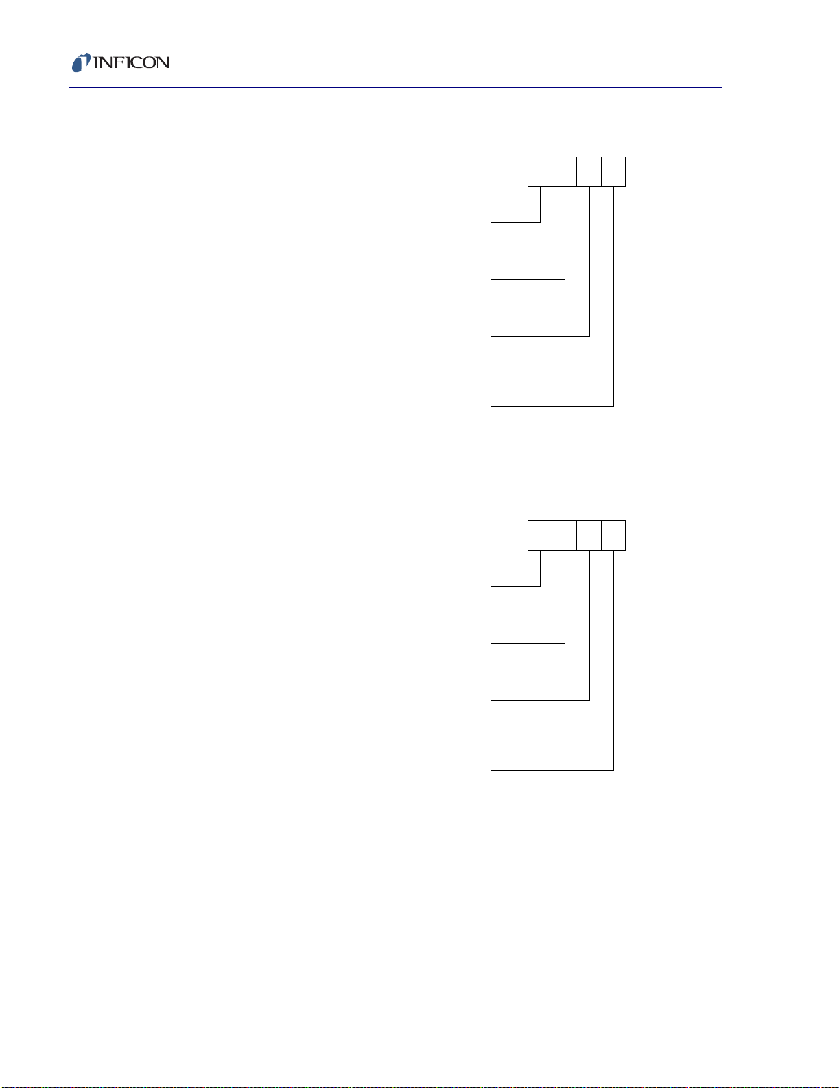
The bright Liquid Crystal Display of the XTC/2 is easily read and keeps the
operator continuously informed with pertinen t deposition da ta including rate,
thickness, phase, rate deviatio n and ela psed time. Special messages such as
Stop, Crystal Fail or Time-Power are clearly presented to reduce operator
uncertainty and eliminate the possibility of costly mis takes.
The XTC/C is a variant of the XTC/2 that has a limited front panel. Instead of
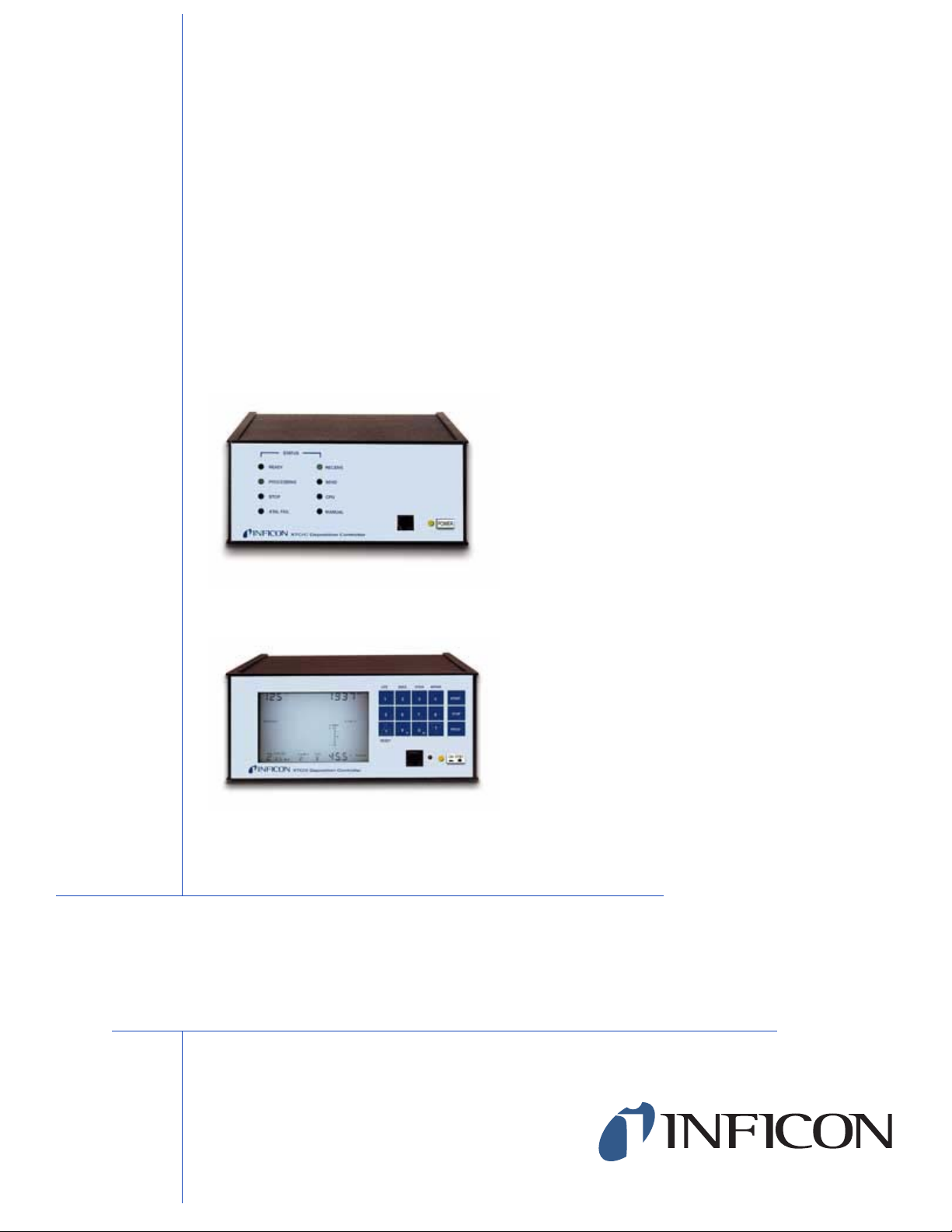
an LCD display , it has 8 LED type status indicators that indicate process status
and instrument functional status. It is primarily designed for use in vacuum
coating plants that have a computer based central controller. The original
equipment manufacturer (OEM) will design a custom user input-output syst em
through his system controller. Once programmed and started, the XTC/C will
essentially run as independent of the central controller as is desired . The
deposition layer can complete without further intervention, freeing the central
controller for other tasks. Status and data may be queried as frequently as is
desired, however.
XTC/C - XTC/2 Operating Manual
Interaction with the coating system for both units is multifa ceted. All units come
with RS232 and support data rates to 9600 baud. The SECSII protocol is
supported. The optional computer interface is IEEE-488. The in strument is
configured to sequentially control two separate deposition sources with 15 bit
resolution using either PID or integrating type controller algorithms. Twelve
relays are used to manipulate various external devices such as source and
sensor shutters, heaters or valves. Lower power outputs are u sed to control the
IPN 074-183X
position of multi-hearth crucibles. There are eight input lines to provide the
ability to sense and react to discrete external signals.
There are numerous special control functions for accommodating the needs of
the deposition process. Full predeposit pro cessing is provide d, including
shutter delay which allows the establishment of the desired rate prior to opening
the substrate shutter. A Rate Ramp allows the deposition rate to be changed
during the deposit phase. The Ra teWatcher feature allows t he dep osition
stream to be periodically sampled, extendin g the life of the crystal.
These instruments are fully compatible with the complete family of INFICON
transducers, including Dual and CrystalSix®.
1 - 5
Page 22

XTC/C - XTC/2 Operating Manual
1.3 Specifications
At the time of this manual’s writing, the specifications for perform ance are as
published below. INFICON continuously improves its products, affecting the
instrument’s performance.
1.3.1 Specifications XTC/2 and XTC/C
1.3.1.1 General
Usage . . . . . . . . . . . . . . . . . . . . . .Indoor use only.
Altitude Range. . . . . . . . . . . . . . . .Up to 2000 m (6,561 ft)
Pollution Degree . . . . . . . . . . . . . .1—No pollut ion occurs
Overvoltage Category . . . . . . . . . .2—Local level, appliances, etc.
Cleaning . . . . . . . . . . . . . . . . . . . .The unit enclosure can be safely cleaned
with a mild detergent or spray cleaner
designed for that purpose. Care should be
taken to prevent any cleaner from entering
the unit.
1.3.1.2 Measurement
Crystal Range & Precision. . . . . . .6.0 to 5.0 MHz +/- .05 Hz
Thickness & Rate Resolution. . . . .0.0617Å (per 250 msec sample)
Thickness accuracy . . . . . . . . . . . .0.5%
Measurement frequency . . . . . . . .4 Hz
1.3.1.3 Source Controls
Source-Control Voltage . . . . . . . . .0 to +/- 10 v
Number of Sources . . . . . . . . . . . .2
Resolution . . . . . . . . . . . . . . . . . . .15 bits over full range (10 v)
Update Rate . . . . . . . . . . . . . . . . .4 Hz max.
Maximum Load . . . . . . . . . . . . . . .400 Ohm (100 Ohm internal impedance)
(per 250 msec sample)
Material density = 1.0; Z-Rati o = 1.0;
crystal frequency = 6 MHz.
Å/S/M = Angstroms/second/measurement.
IPN 074-183X
1 - 6
Page 23

1.3.1.4 Input/Output
Inputs . . . . . . . . . . . . . . . . . . . . . . 9 TTL inputs
Outputs
a) relay . . . . . . . . . . . . . . . . . . 12 SPST 2.5-amp relays rated
b) crucible select . . . . . . . . . . . 8 open col lector
Scan/Change Rate . . . . . . . . . . . . 4 Hz
1.3.1.5 Recorder Output
Voltage . . . . . . . . . . . . . . . . . . . . . 0 to +10 v
Resolution . . . . . . . . . . . . . . . . . . 13 bits over full range
Update Rate . . . . . . . . . . . . . . . . . 4 Hz
Function . . . . . . . . . . . . . . . . . . . . Rate / Thickness / Mass
Maximum Load . . . . . . . . . . . . . . . 2.0 KOhm (100 Ohm internal impedance)
XTC/C - XTC/2 Operating Manual
@ 30 V(dc) / 30 V(ac) / 42 V(peak) max.
(5 volt DC max sink, 5 TTL loads)
(one reserved for sign)
1.3.1.6 Display
Applies to XTC/2 only; the XTC/C provides LED annunciators.
Type . . . . . . . . . . . . . . . . . . . . . . . 4x multiplexed custom LCD with backlight.
If desired, backlight automatically dims
during prolonged period of inactivity,
automatically brightening when a ctivity
begins.
Thickness Resolution . . . . . . . . . . 1 Å
Rate Resolution . . . . . . . . . . . . . . .1 Å for 1 to 99.9 Å/sec
1 Å for 100 to 999 Å/sec
Update Rate . . . . . . . . . . . . . . . . . 1 Hz
IPN 074-183X
1.3.1.7 Process Recipe Storage
Film Programs . . . . . . . . . . . . . . . 9, 30 variables per program
Process layers . . . . . . . . . . . . . . . 3
1 - 7
Page 24

XTC/C - XTC/2 Operating Manual
1.3.1.8 Hardware interface
Sensors
Single. . . . . . . . . . . . . . . . . . . .2
Dual . . . . . . . . . . . . . . . . . . . . .1
CrystalSix. . . . . . . . . . . . . . . . .2
Sources. . . . . . . . . . . . . . . . . . . . .2 BNC female
Crucible Locations. . . . . . . . . . . . .8, 1 of 8 and BCD encoded
I/O
Standard (inputs/outputs) . . . . .8/12
Optional . . . . . . . . . . . . . . . . . .None
Communications
Standard. . . . . . . . . . . . . . . . . .RS232C
Optional . . . . . . . . . . . . . . . . . .IEEE
Chart Recorder . . . . . . . . . . . . . . .1 BNC female
1.3.1.9 Operation
Power Requirements
Operating Temperature . . . . . . . . .0 to 50 °C (32 to 122 °F)
Size . . . . . . . . . . . . . . . . . . . . . . . .3.5" H x 8" W x 12" D
Weight. . . . . . . . . . . . . . . . . . . . . .6 lb. (2.7 kg)
"115 V" input range. . . . . . . . . .90 to 132 V(ac), 49 to 61 Hz, 45 VA max.
fused at 3/8 Amp Type T fuse
"230 V" input range . . . . . . . . .180 to 264 V(ac), 49 to 61 Hz, 45 VA max.
fused at 3/16 Amp Type T fuse
(89 mm x 203 mm x 305 mm)
IPN 074-183X
1 - 8
Page 25

XTC/C - XTC/2 Operating Manual
1.3.2 Transducer Specifications (optional)
Max. Bakeout
Temperature*
CrystalSix Sensor 130 °C 3.5" dia. x 2.0" high
Standard Sensor 130 °C 1.063" x 1.33" x .69" high
Standard Sensor
with Shutter
Sputtering Sensor 105 °C 1.36" dia. x .47" high
Compact Sensor 130 °C 1.11" x 1.06" x 1.06" high
Compact Sensor
with Shutter
UHV Bakeable
Sensor
UHV Bakeable
Sensor with Shutter
Dual Sensor 130 °C 1.45" x 3.45" x 1.70" high
Shutter Assembly 400 °C two models available N/A 300-series SS 750-210-G1
*For Bake only; waterflow is required for actual deposition monitoring. These temperatures are conservative maximum
device temperatures, limited by the properties of Teflon (PTFE) at higher temperatures. In usage, the water cooling allows
operation in environments that are significantly elevated, without deleterious affects.
**Aluminum body for heat transfer.
130 °C 1.06" x 2.24" x .69" high
130 °C 2.08" x 1.62" x 1.83" high
450 °C 1.35" x 1.38" x .94" high
400 °C 1.46" x 1.37" x 1.21" high
Size (Max. Envelope) Water Tube &
Coax Length
30" (762 mm) 304 SS (plate,
(89 mm dia. x 51 mm high)
30" (762 mm) 304 SS 750-211-G1
(27 mm dia. x 34 mm x 17.5 mm high)
(27 mm dia. x 57 mm x 17.5 mm high)
(34.5 mm dia. x 11.8 mm high)
(28 mm x 27 mm x 27 mm high)
(53 mm x 41 mm x 46 mm high)
(34 mm x 35 mm x 24 mm high)
(37 mm x 35 mm x 31 mm high)
(37 mm x 88 mm x 43 mm high)
30" (762 mm) 304 SS 750-211-G2
30" (762 mm) Au-plated BeCu 007-031
30" (762 mm) 304 SS 750-213-G1
30" (762 mm) 304 SS 750-213-G2
12" (305 mm)
20" (508 mm)
30" (762 mm)
12" (305 cm)
20" (508 cm)
30" (762 cm)
30" (762 mm) 304 SS 750-212-G2
Body & Holder IPN
750-446-G1
holders, & material shield)**
304 SS 007-219
007-220
007-221
304 SS 750-012-G1
750-012-G2
750-012-G3
750-005-G1
(Sputtering)
1.3.3 XIU (Crystal Interface Unit) Specifications
The XTC/2 Series instruments use a new type of "passive intelligent" oscillator.
IPN 074-183X
It is available with cable lengths of 15’ (4.572 m), 30’ (9.144 m), 50’ (15.24 m),
and 100’ (30.28 m) as IPN 757-305-G15, G30, G50, or G100, respectively.
Conventional, active style oscillators do not work with these instrum ents.
In-vacuum cable lengths to a maximum of 2 m (6.6’) are supported with this new
technology.
1 - 9
Page 26

XTC/C - XTC/2 Operating Manual
1.4 Guide to the Use of the Manual
This manual is configured to be used by both experie nced and inexperie nced
deposition process engineers. For those with significant experience, especially
on INFICON controllers, nearly all pertinent infor mation is containe d in Chapter
2, Quick Use Guide. Other sections contain the details that supplement the
information in the quick use section .
Every user should read the complete ma nual. It is strong ly sugges ted that t he
user or installer follow the following plan to gain the most information in the
shortest period of time.
Register the instrument to receive updates and important information from
the factory.
Read section 1.1.1, Notes, Cautions, Warnings, on page 1-1 to understand
the safety related issues.
Read Chapter 2, Quick Use Guide, to become familiar with the instrument’s
needs and capabilities. Use the other sections of the manual to supplement
areas where you do not feel you have an adequate un derstanding of the
material. Throughout Chapter 2 there will be frequent referenc es to the
manual sections that provide more detailed information. The final sections
of the Chapter 2 build the understanding of the full use of the instrument in
a logical progression, as suggested in section 2.3 on page 2-8.
1.5 XTC/C Users and Installers Note
The XTC/C can do anything that an XTC/2 can do, but it must be controlled
through the computer interface. In order to install and use this instrument
effectively , all aspects of XTC/2 operation must be understood. Because of this
additional burden, it is probably not cos t effective for an end-user of a singl e
unit to purchase and install the XTC/C version.
WARNING
There are no user serviceabl e compon ents within the
instrument case.
Potentially lethal voltages are present when the line
cord, System I/O or Aux I/O are connected.
Refer all maintenance to qualified personnel.
IPN 074-183X
1 - 10
Page 27

XTC/C - XTC/2 Operating Manual
1.6 Related Manuals
Transducers are covered under separate manuals.
IPN Transducer Type
074-154 . . . . . . Bake able
074-155 . . . . . . Cry stalSix
074-156 . . . . . . Sin gle/Dual/Compact
074-157 . . . . . . Sputtering
1.7 How To Contact Customer Support
If you cannot find the answer to your quest ion in this man ual, please co ntact
one of the following Customer Support groups after deciding whether:
your dif ficulty is with how you are using the instrument—in this case, cont act
Application Support.
or
your instrument needs repair—in this case, contact Field Service and
Repair Support.
When you contact Customer Support, please have this manua l at hand, a long
with the following information:
The serial number for your instrument.
A description of your problem.
An explanation of the corrective action that you may have already
attempted.
The exact wording of any error messages that you have received from the
instrument.
IPN 074-183X
Within the USA, you may reach Customer Support at the following phone
numbers. Please contact the location that is closest to you. If you are located
outside of the USA, please contact your sales office. A complete listing of
INFICON Worldwide Service Centers is available at www.inficon.com.
1.7.1 Application Support
Austin, TX. . . . . . .ph. 512-448-0488 . . . . . . . . . fax 512-448-0398
San Jose, CA . . . .ph. 408-361-1200 ext. 125 . . fax 408-362-1556
Syracuse, NY . . . . ph. 315-434-1128 . . . . . . . . . fax 315-437-3803
If you are located outside the USA, please contact your sales office. A complete
listing of INFICON Worldwide Service Centers is available at www.inficon .com.
1 - 11
Page 28

XTC/C - XTC/2 Operating Manual
1.7.2 Field Service and Repair Support
Austin, TX . . . . . . ph. 512-448-0488. . . . . . . . . .fax 512-448-0398
San Jose, CA . . . . ph. 408-361-1200 ext. 12 0 . . .fax 408-362-1556
Syracuse, NY . . . . ph. 315-434-1167. . . . . . . . . .fax 315-434-25 51
If you are located outside the USA, please contact your sales office. A complete
listing of INFICON Worldwide Service Centers is available at www.in ficon.com.
1.7.3 Returning Your Instrument
Do not send your instrument without first speaking with a Customer Support
Representative.
You must obtain an RMA (Return Material Authori zation) num ber from the
Customer Support Representative. If the delivery of a package without an RMA
number is attempted, INFICON will refuse the delivery and the package will be
returned to you.
If your instrument has been exposed to process materials, you will be required
to complete a Declaration Of Contamination form.
1 - 12
IPN 074-183X
Page 29

XTC/C - XTC/2 Operating Manual
Quick Use Guide
2.1 Unpacking, Initial Inspection and Inventory
2.1.1 Unpacking and Inspection Procedures
1 If you haven’t removed the instrument from its shipping containers, do so
now.
2 Carefully examine the unit for damage that may have occurred during
shipping. This is especially important if you notice signs of obvious rough
handling on the outside of the cartons. Report any damage to the carrier and
to INFICON, immediately.
3 DO NOT discard any packing materials until you have taken inventory and
have verified proper instrument operation to you r satisfactio n. See section
2.2 on page 2-4 for voltage selection and section 3.6 on page 3-11 for test
mode operation.
Chapter 2
2.1.2 Inventory
Make sure you have received all of the necessary equipment by checking the
contents of the shipping containers with the parts list below. INFICON ships
these products on a feature-option basis. Check your order for the part number
before comparing to the lists below.
IPN 074-183X
2 - 1
Page 30
XTC/C - XTC/2 Operating Manual
2.1.2.1 XTC/2 System Configuration
BASIC CONFIGURATION IPN # CODE#
115V 50/60 Hz 757-500-G1 1
230V 50/60 Hz 757-500-G2 2
Computer Communications Module
None 757-211-G1 1
IEEE-488 Parallel 760-142-G1 2
Remote Module
None 0
Hand Controller 755-262-G1 1
Rack Mounting
None 0
1 Unit Mounting Kit 757-212-G1 1
2 Unit Mounting Kit 757-212-G2 2
XTC/2 ---
2.1.2.2 XTC/C System Configuration
BASIC CONFIGURATION IPN # CODE#
115V 50/60 Hz 759-500-G1 1
230V 50/60 Hz 759-500-G2 2
Computer Communications Module
None 757-211-G1 1
IEEE-488 Parallel 760-142-G1 2
Remote Module
None 0
Hand Controller 755-262-G1 1
Rack Mounting
None 0
1 Unit Mounting Kit 757-212-G1 1
2 Unit Mounting Kit 757-212-G2 2
XTC/C ---
IPN 074-183X
2 - 2
Page 31

2.1.2.3 Ship Kit - XTC/2 XTC/C
Both instruments are shipped with the following accessories. To find which
accessories were shipped with your unit look for th e "X" which represents the
voltage of your particular instrument and follow that column.
Table 2-1 Accessories
Qty
G2 G1
Item
01 - X 757-203-G1 Ship Kit - XTC/2 & XTC/C 115V
02 X - 757-203-G2 Ship Kit - XTC/2 & XTC/C 230V
03 - 1 068-0385 North American Power Cord, shielded
04 1 - 068-0390 European Power Cord, shielded
05 1 1 051-485 Conn 9 Pin Male D/Sub Sod. Cup
06 1 1 051-620 Cable Clamp 11.3015
07 2 2 051-483 Conn 25 Pin Female D/Sub Sod. Cup
(230V)(115V) IPN Number Part # and/or Description
XTC/C - XTC/2 Operating Manual
08 2 2 051-619 Cable Clamp
09 - 1 062-011 3/8 Amp Fuse Type T
10 1 - 062-053 3/16 Amp Fuse Type T
11 4 4 070-811 8014 Bumpon Feet
In addition, you have already found a copy of th is manual, IPN 074-1 83.
IPN 074-183X
2 - 3
Page 32

XTC/C - XTC/2 Operating Manual
2.2 Voltage Selection
Voltage selection is re quired only betwee n low (nominal 10 0-120 V) and high
(nominal 200-240 V) ranges. There is no distin ction between 50 and 60 Hz
supplies. Refer to section 1.3.1 on page 1-6 for specific power requirements.
CAUTION
Verify that the correct fuse is in place by visually
inspecting the fuse for the proper rating. Use of an
improperly sized fuse may create a safety hazard.
For 100-120 V(ac) operation use a 3/8 Amp Type T fuse.
For 200-240 V(ac) operation use a 3/16 Amp Type T fuse.
NOTE: These instruments are designed to operate betwee n 90 V(ac) a nd
132 V(ac) on Low Range and between 180 V(ac) and 264 V(ac) on
High Range.
WARNING
This instrument has line voltage present on the
primary circuits whenever it is plugged into a main
power source.
Potentially lethal voltages are present when the line
cord, system I/O or aux I/O are connected.
This instrument must be disconnect ed from the m ain
power source before inspecting or replacing th e fuse.
IPN 074-183X
2 - 4
Page 33

XTC/C - XTC/2 Operating Manual
To inspect the fuse, proceed as follows.
1 Pry open the power e ntry modu le cove r. See Figure 2-1.
Figure 2-1 Opening the Power Entry Module Cover
2 Pry the fuse holder out of th e housing. See F igure 2-2.
Figure 2-2 Removing the Fuse Holder
IPN 074-183X
2 - 5
Page 34

XTC/C - XTC/2 Operating Manual
3 Inspect the fuse. See Figure 2-3.
Figure 2-3 Clip, Fuse Holder, Fuse
Conversion Clip
Fuse
Holder
Fuse
The Corcom fuse holder has chambers for two 1/4" x 1 1/4" (5 mm x 20 mm)
fuses. Since only one fuse is used, that fuse must be on the live (hot) side and
a conversion clip is inserted to bridge the un used fuse cham ber in the neutral
side.
An additional function of the conversion clip is to act as a polarization key to
assure that only the neutral line can be bridged leaving the live (hot) line always
fused. A special feature has been built into the live side of the f use holder
compartment of the housing. It will interf ere with th e conversi on clip and
therefore stop the fuse holder from being ins erted fully int o the housing if the
clip is on the live side.
When the power entry module is flipped around for voltage changing , the
conversion clip must be re-installed to the other side. Otherwise, the fuse holder
will not seat completely into the housing and the po wer entry module will no t
function.
The proper location of the conversion clip is at the left hand side of the voltage
number selected, that is, the upright voltage numb er. See Figure 2-4.
IPN 074-183X
2 - 6
Page 35

XTC/C - XTC/2 Operating Manual
Figure 2-4 Proper Clip and Fuse Location
Once the fuse and clip have been configured, the fuse holder is inserted into
the power entry module housing with the fuse towards the bottom of the
instrument (and the clip towards the top) with the desired voltage showing
through the hole into the cover.
IPN 074-183X
2 - 7
Page 36

XTC/C - XTC/2 Operating Manual
2.3 Installation Guide and Schematic
Many experienced deposition monitor users will be able to fu lly install and use
the instrument by studying the installation schem atic, Figure 2-5 on the next
page, and the S tate Seque nce Diagrams, Figure 4-2 on page 4-2, Figure 4-3 on
page 4-3, Figure 4-4 on page 4-4, and Figure 4-5 on page 4-5.
A more systematic approach would be to start by reviewing the two figures and
then following the procedure below.
WARNING
Completely review section 1.1 on page 1-1 on safety.
All warnings in this section, as well as ones fo und in
other sections listed below, must be followed to ensure
the safety of the personnel operating this instrument.
1 Check for correct line voltage, sect ion 2.2 on page 2-4.
2 Verify basic unit operation by exercising it in the Test Mode, section 3.6 on
page 3-11.
3 Review the system interface capability as outlined in section 2.6 on pa ge
2-18. Be especially attentive of the special fe atures availab le on the
configuration switches, section 2.6.2 on page 2-19
4 Wire the necessary connectors following the installation procedures in
sections section 3.1 on page 3-1, section 3.2 on page 3-1, and section 3.3
on page 3-4.
5 Review the front panel controls and display descri ption per section 2.4 on
page 2-10 for the XTC/2 or section 2.5 on page 2-16 for the XTC/C.
6 Program the desired film parameter values per section 4.1 o n page 4-1 and
section 4.2 on page 4-6.
7 Verify the operation of the just programmed film utilizing the Test Mode.
8 Attach the XIU (757-305-G15, G30, or G100) to an existing transdu cer or
install a new transducer following the guidelines of section 3.5 on page 3-7
and Figure 3-3 on page 3-8.
IPN 074-183X
2 - 8
9 Exit the Test Mode and deposit when rea dy.
Page 37

STOP
INCR DE CR
X
T
A
L
XTC/C - XTC/2 Operating Manual
(Optional)
IPN 755-262-G1
Power Controller
Hand Held Manual
S
W
I
T
C
H
[To front of instrument]
IEEE 757-211-G1
Option
on sensor connector 1.
Outputs
1,2 Thickness setpoint
3,4 Feedtime (SOAK 2)
5,6 Crystal Fail
7,8 Alarms
9,10 Source 1 / Source 2
11,12 End Deposit
Inputs
13 Input common (GND)
14 Crucible valid
15,16,17 Input common (GND)
Open Collector Outputs
18 Crucible select 1
19 Crucible select 2
20 Crucible select 3
21 Crucible select 4
22 Crucible select 5
23 Crucible select 6
24 Crucible select 7
25 Crucible select 8
NOTE: Crucible select is also BCD encoded
Description
Pin #
1 Not used
2 TXD Data transmitted from XTC
3 RXD Data received by XTC
4 Not used
5 GND Signal ground
6 DTR Output from XTC indicating ready to transmit
7 CTS Input to XTC indicating stop transmitting
8 Not used
9 GND Shield ground
Pin #
Also Available
Source Shutter 2 3,4
Sensor Shutter 2 7,8
Stop 8,10
End Of Process 11,12
Inputs
Input Common 13,14,15,16,17
Start Deposition 18
Stop Deposition 19
End Deposit 20
Sample Initiate 21
Sample Inhibit 22
Crystal Fail Inhibit 23
Zero Thickness 24
Outputs
5
6
Soak 2 Hold 25
1
2
Sensor Shutter 1
[N.O. Relay Contact]
From Local Line Power
100-120 V(ac) ±10%
200-240 V(ac) ±10%
Sensor Shutter 1
Outputs Pin #
Optional
Chart
Recorder
Earth
Ground
50-60 Hz
Feed Thru
IPN 750-030-G1
(Oscillator Kit 757-305-GXX: option)
(Option)
Cooling
Water
Source Shutter 1
[N.O. Relay Contact]
Source Shutter 1
Figure 2-5 Installation Guide Schematic
Air, 80 PSI, 110 PSI Max.
Optional
Cajon
Coupling
IPN 074-183X
Standard Sensor with Shutter
IPN 750-211-G2
(Option)
Sensor
Shutter
Source
Shutter
Source to Sensor
10” Minimum
Beam Gun
Such As Electron
Source Controller
Actuator
Pneumatic
XIU (Oscillator)
IPN 757-302-G1
In
Out
Shutter
IPN 007-199
Power Supply
Solenoid Assy.
Power Supply
24 V(ac) or V(dc)
Rotary
Feed Thru
Air
Actuator
Power Supply
Compressed
2 - 9
Page 38

XTC/C - XTC/2 Operating Manual
2.4 XTC/2 Front Panel Description
The description of the XTC/2 front panel is divided into two sections, the display
area and the front control panel.
Figure 2-6 Front Panel XTC/2
1 2345 6
7
8
9
18
2.4.1 XTC/2 Front Control Panel Description
1— LCD DISPLAY
Highly visible display of current information. See section 2.4.2 on page
2-12 for details.
2— LIFE
Pressing the 1 key momentarily switches the display to percent of crystal
life used, software version, crystal frequency, and S and Q values, when
the display is in the operate mode.
3— ZERO
Pressing the 2 key zeros the displayed thickness when the display is in the
operate mode.
4— XTSW
Crystal Switch. Pressing the 3 key advances the CrystalSix to the next
available crystal or changes the active crystal of the dual head when the
display is in the operate mode. (See section 4.15.1 on page 4-25.)
5— MPWR
Manual. Pressing the 4 key places the unit in manual power control or rate
control mode when the display is in the operate mode.
1011121314151617
IPN 074-183X
2 - 10
6— START
Initiates action. (Starts State Sequencing, see Figure 4-2 on page 4-2 and
Figure 4-3 on page 4-3.)
7— STOP
Halts State Sequencing, see Figure 4-2 on page 4-2 and Figure 4-3 on
page 4-3.
8— PROG
Program. Toggles the display between the program and operate mod es.
Page 39

XTC/C - XTC/2 Operating Manual
9— ON/STBY
Switches secondary power of the instrument between ON and STANDBY.
10—
Green LED indicates that the unit is connected to an active line power
source and the ON/STBY switch is set to ON.
11—
Access to adjust LCD contrast, see section 6.1 on page 6-1.
12—
Connection for optional manual power and crystal switch hand controller
(IPN 755-262-G1).
WARNING
This connector is not for telecommunications
equipment. Do not connect a phone to this connector.
13—
Enter and cursor down. Two function switch used when the display is in the
program mode. All numeric and "Y" "N" parameter entries need to be
followed by a . Also used to manuall y decrease sou rce power when in
MPWR and the display is in the operate mode.
14— 0/N
Zero or no. Two function switch used when the display is in the program
mode. Also, places unit in communications set up mode if held down during
power up, see section 3.8.1 on page 3-20.
15— 9/Y
Nine or yes. Two function switch used when display is in progra m mode.
16— /RESET
IPN 074-183X
Clear and cursor up. Two function switch that is also used to "reset" the
instrument to the beginning of a process from a STOP state. Also used to
increase source power when in MPWR and the display is in the operate
mode.
17— DIGITS (0-9)
Decimal based key pad for data entry. If the nine key is held down during
power-up, all of the LCD segments will remain lit until t he key is rel eased ,
see Figure 2-7 on page 2-12.
18—
Optional mounting kit, (IPN 757-212-G1) for mo unting one unit in f ull rack
or (757-212-G2) for mounting two units side by side in full rack .
2 - 11
Page 40

XTC/C - XTC/2 Operating Manual
2.4.2 XTC/2 Display Description
Figure 2-7 XTC/2 Display
1 23
20
19
18
17
16
15
14
4
5
6
7
8
910111213
1— RATE DISPLAY GROUP
Indicates the deposition or etching rate in Å/sec or the version level of the
installed firmware when the LIFE key is pressed and display is in the
Operate mode. When the display is in the Program mode , it is used to
display and enter the values of parameters requiring three significant digits.
2— COMMUNICATIONS & TEST GROUP
A message area that:
a. Indicates that the I/O has been put into external communication control
through the R-15 through R-18 commands.
b. The instrument is in TEST mode, see section 3.6 on page 3-11.
c. The in strument is send ing or receiving an exte rnal comput er
COMMunication command.
3— DEPOSITION (ETCH) RATE and THICKNESS SUBGROUP
Indicators and annunciators for parameter entry of starting DEPosition
RATE, film’s FINAL THicKness and an intermediate THicKness SetPoinT.
4— THICKNESS and FREQUENCY GROUP
Indicates the deposited (etched) thickness or the active crystal’s frequency
in KHz when the LIFE key is pressed when the display is in the operate
mode. When the display is in the Program mode i t is us ed to di splay and
enter the values of parameters that require four signific ant digits.
5— RATEWATCHER SUBGROUP
Indicator annunciator and cursor array for the definition of the RateWatcher
parameters when the display is in the Program mode. Used as an indicator
of the SAMPLE and HOLD deposition substrates when the display is in the
Operate mode.
IPN 074-183X
2 - 12
Page 41

XTC/C - XTC/2 Operating Manual
6— RATE DEVIATION GROUP
A graphic annunciator that displays the current deviation of the deposition
rate from the value of the active film’s DEP RATE pa ra me t er. Thi s
annunciator structure is updated each 250ms measurement when the
display is in the Operate mode. A 0% deviation is indicated when the
computed value is less than +/-2%. The plus or minus 10% val ues are
indicated when the computed value is more than +/-10%, resp ectively.
7— ACTIVE CRYSTAL INDICATION GROUP
A graphic annunciator that provid es info rmation con cerning t he prese ntly
active crystal or the availability of backup crystals. Its meaning is somewhat
altered by the instrument’s configuration regarding the crystal switch type,
see section 2.6.2 on page 2-19.
a. If the instrument is configured for "Single Heads", the annunciator will
indicate which sensor is active.
b. If the instrument is configured for "Dual Sensor Head", the annunciator
will display the number representing the active crystal’s "sensor
number." Whenever the instrument is operating with the secondary
(backup) crystal the number of the backup crystal will be flashing as an
indication of the lack of a subsequent backup crystal.
c. If the instrument is configured for one or two CrystalSix, the annunciator
will display the numbers of all crystals of the active sensor’s output that
are "good." The "active" crystal’s number will flash. The absence of all
numbers may also indicate that the switcher is not opera ting.
8— STATUS MESSAGE GROUP
A group of annunciators that provide information conc erning the state of
the instrument.
a. READY — when illuminated the instrument will accept a start command
to begin state processing of the active layer.
b. STOP — when illuminated indicates that the instrument is in the STOP
state, see section 4.3 on page 4-9 and section 4.4 on page 4-10.
c. TIME PW R — when illuminated ind icates that the inst rument is in the
Time-Power state. See section 4.12 on page 4-22 .
d. CONTINUE — when illuminated the instrument will again execute state
IPN 074-183X
processing of the active layer, allowing for any previously accumulated
material, when the ST ART key is pressed. Pressing the RESET key prior
to the ST AR T key reset s the process to layer 1; see section 4.4 on page
4-10.
e. MANUAL —when illuminated the instrument is in the manual power
control mode and the source’s power level is modified by eit her the
optional hand controller or the front panel keys (XTC/2 only).
f. XTAL FAIL — this indicator illuminates when the active crystal has
failed. In the case of instruments configured for dual or CrystalSix
operation it indicates that no further crystals are availab le.
2 - 13
Page 42

XTC/C - XTC/2 Operating Manual
9— POWER and PROCESS GROUP
Indicates the relative source power when the display is in the Operate
mode and displays the % xtal life when the LIFE key is pressed. When th e
display is in the Program mode, these three digits are used for the entry of
some 3 digit film parameter values. It is also used to define the instrument’s
sequencing of multi-layers, see section 2.9 on page 2-36.
10— SENSOR and SOURCE SUBGROUP
The annunciators and cursors for the definition of a film’s:
a. SENSOR # — designates the active or primary (for dual head) sensor
as 1 or 2.
b. SOURCE # — designates the film’s active source control output
as 1 or 2.
c. CRUCIBLE # — de signates the activ e film’s crucible pocket as 1-8,
corresponding to crucible select outputs 1-8. A value of 0 disables th is
parameter and associated outputs; see section 2.6.5 on page 2-24 .
11— CONTROL PARAMETER SUBGROUP
The annunciators and cursors for entering the values used in a film’s Rate
Control algorithm; see section 4.5 on page 4-11.
12— CRYSTAL and PROCESS SUBGROUP
When the display is in the Program mode:
a. the XTAL SWCH parameter ’s values are entered fo r S & Q as labeled.
b. the "FILM #" parameter value defines the particular film’s (1-9) values
being programmed/displayed.
c. The "LYR #" defines the process layer to be assigned a film. This
parameter works with the power and process display group .
When the display is in the Operate mode:
a. "FILM #" parameter value defines the film being executed and the
"LAYER #" parameter value defines the layer being executed.
2 - 14
13— TIMER GROUP
When the display is in the Operate mode, serves as the el apsed time
indicator and unit annunciator. Also displays S & Q values when the LIFE
key is pressed. The values in the S accumulator replace the time display
while the LIFE key is pressed. When the key is released the value of the Q
accumulator is shown for about 1 second. Used for entering and displaying
the value of time-based parameters when the display is in the Program
mode.
14— CALIBRATION SUBGROUP
Annunciators and cursors used when the display is in the Program mode.
Allows conversion of the crystal’s fr equency shift to material thickness; see
section 5.1 on page 5-1 through section 5.4 on page 5-3.
IPN 074-183X
Page 43

XTC/C - XTC/2 Operating Manual
15— CRYSTAL FAIL SUBGROUP
Annunciators and cursors used when the display is in the program mode to
determine tolerated levels of crystal performance a nd subseq uent
instrument actions.
a. TIME PWR Y-N — defines the action taken when a crystal fails; see
section 4.11 on page 4-22.
b. XTAL SWCH S-Q — a two parameter data field used with the digits in
the crystal and process subgroup. These are used to set the level of so ft
crystal failures tolerated; see section 4.6 on page 4-14.
16— POST DEPOSIT SUBGROUP
Annunciators and cursors used to define the source’s post deposition
power levels; see section 4.9.3 on page 4-21.
17— RATE RAMP SUBGROUP
Annunciators and cursors used to define a change in de position rate during
the deposit state; see section 4.7 on page 4-19.
18— DEPOSIT STATE INDICATOR
Annunciator used to indicate that the instrument is exe cuting the de posit
state of the active film; see section 4.1 on page 4-1.
19— PRE DEPOSIT SUBGROUP
Annunciators and cursors used to define the pred eposition source
conditioning when the display is in the Program mode.
a. RISE TIME 1-2 — defines the length of the rise 1 (2) state.
b. SOAK PWR 1-2 — defines the power level(s) of the
soak 1 (2) state.
c. SOAK TIME 1-2 — define s the length of the soak 1 (2) state.
These parameters, together, define a two step source power profile with
linear changes in power between levels as shown graphically in Figure 2-8.
d. SHUTR DLY Y-N — executes (Y) or skips (N) the shutter delay phase;
see section 4.14 on page 4-23.
Figure 2-8 Source Power Level Profile
IPN 074-183X
2 - 15
Page 44

XTC/C - XTC/2 Operating Manual
20— PROGRAMMING and PHASE INDICATOR GROUP
Annunciators and cursors for navigating, displaying and changing a film’s
individual parameter values when the display is in the Program mode.
The annunciators are also used to indicate the cu rrent state of the film
being executed when the display is in the Operat e mode.
2.5 XTC/C Front Panel Description
Figure 2-9 Front Panel XTC/C
1
2
3
4
56 7 8 910
12
11
1— READY
When the associated LED is illuminated the instrument is in the READY T O
START state.
2— PROCESSING
When the associated LED is illuminated the instrument is state executing
a layer. See Figure 4-2 on page 4-2.
3— STOP
When the associated LED is illuminated the instrument is in the STOP
state.
4— XTAL FAIL
When the associated LED is illuminated the measurement crystal has
failed. In the case of units configured for dual or CrystalSix operation it
indicates that there are no further crystals available.
IPN 074-183X
2 - 16
5— RECEIVE
When the associated LED is illuminated the instrument is receiving
information from the connected computer c ontroller.
6— SEND
When the associated LED is illuminated the instrument is sending
information to the connected computer contro ller.
7— CPU
When the associated LED is illuminated the instrument’s computer is not
operating normally.
Page 45

XTC/C - XTC/2 Operating Manual
8— MANUAL
When the associated LED is illuminated the instrument is capable of
responding to power changes as directed by the optional manual power
controller.
9—
Connection for optional manual power and crystal switch hand controller
(IPN 755-262-G1).
10—
Green LED indicates that the unit is connected to an active line power
source and the ON/STBY switch is set to ON.
11 — ON/ S TB Y
Switches secondary power of the instrument between ON and STANDBY.
12—
Optional mounting kit for mounting one instrument in full rack (IPN
757-212-G1) or for mounting two units side by side in full rack (IPN
757-212-G2).
IPN 074-183X
2 - 17
Page 46

XTC/C - XTC/2 Operating Manual
2.6 Rear Panel Description
The rear panel provides the interface for all external conne ctions to the
instrument.
Figure 2-10 Rear Panel
2
3
2.6.1 Power Module
Allows selection of optional voltages, contai ns the instrument fuse and provides
modular connection to line power. Refer to section 2.2 on page 2-4.
Figure 2-11 Power Module
1
4
5
6
891011
7
2 - 18
IPN 074-183X
Page 47

2.6.2 Configuration Switches 1 & 2
Two eight position DIP switches used to customize the instrument as follows.
Figure 2-12 Configuration Switch
CAUTION
The configuration switches are only read on
instrument power up. If an option is changed, the
instrument must be switched to standby and then
powered up.
XTC/C - XTC/2 Operating Manual
IPN 074-183X
2 - 19
Page 48

XTC/C - XTC/2 Operating Manual
Table 2-2 Configuration Switch Settings
XTC/2 XTC/C
Switch 1 Test Mode (0 = off, 1 = on) Communications
(2
4
)
Address
3
Switch 2 Parameter Lock (0 = off, 1 = on) Communications
(2
)
Address
2
Switch 3 Control Mode (0 = deposit, 1 = etch) Communications
(2
)
Address
1
Switch 4 Stop On Alarms (0 = no, 1 = yes) Communications
(2
)
Address
0
Switch 5 Stop on Max Power (0 = no, 1 = yes) Communications
(2
)
Address
XTC/C Switches 1-5 are only used for the optional IEEE488 (IPN 760-142-G1 or 757-122-G1).
[Addresses 0 to 30 are allowed.]
Switch 6 Recorder Type MSB Communications Protocol
0 = INFICON, 1 = SECS
Switch 7 Recorder Type Baud Rate MSB
Switch 8 Recorder Type LSB Baud Rate LSB
NOTE: for the XTC/2
000 designates Rate, 100 Å/s full scale (unfiltered)
001 designates Rate, 1000 Å/s full scale (unfiltered
010 designates Thickness, 100 Å full scale
011 designates, 1000 Å full scale
100 designates Power %
101 designates Rate Deviation (±50 Å/s)
110 designates Rate 100 Å/s full scale - smoothed
111 designates Rate 1000 Å/s full scale - smoothed
NOTE: for the XTC/C
00 is 9600 baud
01 is 4800 baud
10 is 2400 baud
11 is 1200 baud
Switch 9 Beep On/Off (0=on, 1=off) Checksum (0 = no, 1 = yes)
Switch 10 Backlight Dim (0 = no, 1 = yes) Unused
Switch 11 Start Layer without
backup crystal
(0 = no, 1 = yes) Start Layer
without backup
0 = no, 1 = yes)
crystal
IPN 074-183X
2 - 20
NOTE: See section 4.16 on page 4-26 for description
Page 49

Table 2-2 Configuration Sw itch Settings
XTC/2 XTC/C
XTC/C - XTC/2 Operating Manual
Switch 12 Input Option
Unused
0 = standard
1 = film select
Switch 13 Relay Option
1 = on
Relay 7 = End of Film
Relay 10 = In Process
0 = off
Relay 7 = Thickness Setpoint
Relay 10 = Alarms
1 = on
Relay 7 = End of Film
Relay 10 = In Process
0 = off
Relay 7 = Thickness Setpoint
Relay 10 = Alarms
Switch 14 Crystal Switch Type MSB Crystal Switch Type MSB
Switch 15 Crystal Switch Type LSB Crystal Switch Type LSB
NOTE:
00 designates single head(s)
01 designates one dual head
10 designates one CrystalSix, on SENSOR 1
11 designates two CrystalSixs
Switch 16 Source Control
Voltage polarity 0 = neg, 1 = pos
Source Control
Voltage polarity 0 = neg, 1 = pos
IPN 074-183X
2 - 21
Page 50

XTC/C - XTC/2 Operating Manual
2.6.3 Grounding Stud
Recommended point for connecting the syste m ground strap. Fo r speci fic
recommendations see 3.2, Electrical Grounding and Shielding Requirements.
Figure 2-13 Grounding Stud
2 - 22
IPN 074-183X
Page 51

2.6.4 System I/O
A 25-pin male "D" type connector for interface connection. (See Figure 2-14 on
page 2-24 and section 3.7 on page 3-15 for details.)
Relay# Outputs
*Also used for crystal switch, see section 4.15.1 on page 4-25
Input # Inputs
XTC/C - XTC/2 Operating Manual
Pin # Function
11,2
23,4
35,6
47,8
59,10
Source Shutter 1
Source Shutter 2
Sensor Shutter 1*
Sensor Shutter 2*
STOP
6 11,12 End of Process
13,14,15,16,17
118
219
320
421
522
623
724
825
INPUT Common (GND)
START deposition
STOP deposition
END deposit
Sample initiate
Sample inhibit
Crystal fail inhibit
ZERO thickness
Soak 2 HOLD
IPN 074-183X
2 - 23
Page 52

XTC/C - XTC/2 Operating Manual
2.6.5 AUX I/O
A 25-pin male "D" type connector for interface connection, see Figure 2-14 on
page 2-24 and section 3.7 on page 3-15.
Figure 2-14 25-Pin Type "D" Male Connector
*NOTE: See description of configuration switch 13,
section 2.6.2 on page 2-19.
**NOTE: The crucible select outputs are available BCD encoded on the
Sensor 1 connector, see section 2.6.6 on page 2-25.
Pin # Function
Relay # Outputs (Relays)
7 1,2 Thickness setpoint/End of Film*
8 3,4 Feedtime (SOAK 2)
9 5,6 Crystal fail
10 7,8 Alarms/In Process*
11 9,10 Source 1/Source 2 toggle (closed
when source 2 is active)
12 11,12 End Deposit
Input# Inputs
13 Input common (GND)
9 14 Crucible valid
15,16,17 Input common (GND)
TTL Output # Outputs (Open Collector 1 of 8 encoding)**
1 18 Crucible select 1
2 19 Crucible select 2
3 20 Crucible select 3
4 21 Crucible select 4
5 22 Crucible select 5
6 23 Crucible select 6
7 24 Crucible select 7
8 25 Crucible select 8
IPN 074-183X
2 - 24
Page 53

2.6.6 Sensor 1, Sensor 2
High density 15-pin female "D" type. Input connectors for intelligent oscillators
1, 2 (IPN 757-302 G1). These oscillators are normally supplied with 15 foot (4.5
meter) cables as IPN 757-305-G15. These are specifiable as 30 foot and 100
foot by changing the group (G-xx) designat ion to 30 or 100, re spectively. The
crucible select outputs are open collector BCD encoded only on Sensor 1.
Figure 2-15 15-Pin Type "D" Female Connector
Pin # Description
11 Crucible Select (LSB)
12 Crucible Select
13 Crucible Select (MSB)
14 Ground
15 Ground
XTC/C - XTC/2 Operating Manual
BCD encoding
CAUTION
Only connect to pins 11-15, inclusive. Ignoring this
warning will effect crystal and instrument
performance.
Be sure to follow the best wiring and grounding
practice possible see section 3.2.3 on page 3-3.
IPN 074-183X
2 - 25
Page 54

2.6.7 RS232
XTC/C - XTC/2 Operating Manual
A 9-pin female "D" type connector which enables the instrument to be controlled
by a host computer.
Figure 2-16 9-Pin Type "D" Female Connector
Pin # Description DB9* DB25**
1 Not used 1 2 TXD Data transmitted from XTC2 2 3
3 RXD Data received by XTC3 3 2
4 Not used 4 5 GND Signal ground 5 7
6 DTR Output from XTC indicating ready to transmit 6 6
7 CTS Input to XTC indicating stop transmitting 7 4
8 Not used 8 9 GND Shield ground 9 *Host **IBM compatible computer connector
2 - 26
IPN 074-183X
Page 55

2.6.8 Communication Option
Location of optional computer interf ace.
Figure 2-17 IEEE488 Option
2.6.9 Source 1,2
BNC type female connectors that supply control voltage to the designated
evaporation source power supplies. The outpu t voltage is selected as eith er
plus or minus with respect to the shield by a Configuration Switch. Refer to
section 2.6.2 on page 2-19.
Figure 2-18 BNC Connector
XTC/C - XTC/2 Operating Manual
IPN 074-183X
2 - 27
Page 56

XTC/C - XTC/2 Operating Manual
2.6.10 Manufacturer’s Identification and Serial Number Plate
This plate is installed at final assembly to identify the in strument’s model and
serial numbers.
Figure 2-19 Serial Number Plate
2.6.11 Recorder
A BNC type female connector that supplies analo g voltage prop ortional to rate,
thickness, power or rate deviation. The f unction is determine d by configuration
switches. Refer to section 2.6.2 on page 2-19. See the Remote Command
description in section 3.8.5.6 on page 3-32 for how to choose this function via
the remote communications when using an XTC/C.
Figure 2-20 BNC Connector
IPN 074-183X
2 - 28
Page 57

XTC/C - XTC/2 Operating Manual
2.7 Operation as a Deposition Monitor
Although this instrument is designed as a multi-layer proce ss controller, it is
also easily used as a rate and thickness depos ition monito r. In addition, it is
easily used for many other types of mass measurement applications.
The following discussion is divided into four segmen ts. The first is for
applications that do not require a source shu tter. The second relates to those
that use a source shutter. The third section is a simple a pplicati on of th e
instrument for manual rate sampling. The fourth segment is directed towards
those applications that are nont raditiona l; incl uding b iological, electrop lating ,
etching and the measurement of liquid samples.
2.7.1 Monitoring - Systems Without a Source Shutter
To operate the instrument as a film rate/thickness moni tor only the f ollowing
three parameters need to be programmed. Press the PROG key to place the
display in the program mode and enter the ap propriate va lues for:
DENSITY . . . . . . . . . . . . . . . . . . . Depends on the material to be measured,
see Appendix A, Table of Densities and
Z-ratios.
Z-RATIO . . . . . . . . . . . . . . . . . . . . Depends on the material to be measured,
see Appendix A, Table of Densities and
Z-ratios.
TOOLING 1,2 . . . . . . . . . . . . . . . . Corrects for the geometrical differences
between the sensor and the substrat e, see
section 5.3 on page 5-2. TOOLING 2 is
used for the backup sensor when a dua l
head is used.
Properly mount and attach the ap propriate transduce r (see section 3.5 on page
3-7).
IPN 074-183X
Set the rear panel configuration switches for the appropriate transducer type;
refer to section 2.6.2 on page 2-19.
Press the PROG key to change the display between th e program and op erate
modes.
A STOP is cleared by pressing the START or RESET switch. RESET starts the
process over (i.e., at the beginning of Laye r 1).
Pressing the ZERO key at any time sets the displayed thickness to 000.0 KÅ.
The Rate display group will indicate the evaporation rate and the Thickness
display group will increment accordingly. The front panel controls work
normally.
2 - 29
Page 58

XTC/C - XTC/2 Operating Manual
2.7.2 Monitoring - Systems with a Source Shutter
In addition to measuring rate and thickness, these ins truments can be used to
terminate the deposition at the proper thickn ess. I mplementation requires t hat
the deposition system have a source (or substrate) shutter capable of automatic
operation. The source shutter controller must be wired through the SYSTEM I/O
connector on the rear panel of the instrument. The following parameters (in
addition to those required in the section above ) must also be progra mmed.
DEP RATE. . . . . . . . . . . . . . . . . . .Program to 0.1 Å/sec.
NOTE: Programming the DEP RATE to
0.0 Å/sec skips the Deposit state.
FINAL THK . . . . . . . . . . . . . . . . . .Program to the desired film thickness.
In addition set all of the pre and post deposition parameters to zero (see
Chapter 4, Programming System Operation Details).
The operator manually increases the sou rce power (usi ng the so urce power
supply’s control) to the nominal operating lev el. O nce the u ser i s s atisf ie d, t he
deposition begins when the START switch is pressed. This action zeros the
accumulated thickness display and open s the source shutter. The operator
must then adjust the source power manually to ach ieve the desired rate . The
shutter will close automatically when the final thickness set point is achieved.
2 - 30
IPN 074-183X
Page 59

2.7.3 Rate Sampling
It is possible to use these instruments to periodically sa mple the rate i n a
deposition system. A shuttered transducer must be used, see section 3.4 on
page 3-6.
NOTE: It will be useful to refer to the separate INFICON Crystal Sensor Manual
(see list below) for transducer and actuator control valve installation.
IPN Type
074-154 . . . . . . Bakeable
074-155 . . . . . . CrystalSix
074-156 . . . . . . Standard, Compact and Dual
074-157 . . . . . . Sputtering
1 Electrically connect the pneu matic shutter actu ator control valve (I PN
007-199) to the sensor shutter pins of the SYSTEM I/O connector.
CAUTION
XTC/C - XTC/2 Operating Manual
Verify proper electrical connection, do not confuse the
source shutter relay with the sensor shutter relay.
2 Program the DEP RATE parameter to 0.1 Å/sec.
NOTE: Programming the DEP RATE to 0.0 Å/sec skips the Deposit state.
3 Program the FINAL THK parameter to a value which allows approximately
20 seconds of material accumulation onto the sensor head . For example, if
the nominal rate is 20 Å/sec, set the final thickness to 20 sec x 20 Å/sec =
400Å. If the sample time is too short there could be errors indu ced by
temperature transients across the monitor crystal.
A sample is initiated by pressing START (from the READY mode). This zeros
the displayed thickness and opens the sensor shu tter. The operator may view
IPN 074-183X
the deposition rate display (allowing it to stabilize) and then comparing it to the
desired rate. If a time longer than the progra mmed sample time is requ ired to
adjust the actual deposition rate the operator can press the MPWR key. Once
the adjustments are completed, again pressing the MPWR key closes the
shutter.
2 - 31
Page 60

XTC/C - XTC/2 Operating Manual
2.7.4 Nontraditional Applications
In addition to their normal application as a deposition monitor/controller, quartz
crystal microbalances have significant utility as generalized mass sensors. This
particular instrument family is capable of measuring mass increases or
decreases on the face of the monitor crystal to an accuracy of +/- 0.61 7
nanograms/cm
mass be well adhered to the face of the crystal or improper readings will be
taken. It is especially important to recognize this requirement for measurements
of liquids or other non-rigid materials. INFICON’s 6MHz crystal holders have an
open area of ~0.535 cm
the individual crystal holder be measured with a traveling microsc ope to
determine the exact opening area.
2.7.4.1 Etching
The instrument may be configured to display the thick ness or mass removed
from the face of a crystal. It is imperative that the material be remo ved uniformly
over the active area of the crystal or improper readings will be taken. This
inaccuracy occurs because of radial mass sensitivity differences across the
face of the monitor crystal.
2
(density = 1.00, z = 1.00). As always, it is imperative that the
2
. For the highest accuracy possible, it is suggested th at
The etch mode is established by setting a configuration switch (refer to section
2.6.2 on page 2-19) on the back of the instrument.
The unit is operated normally, with the ZERO or START keys used to zero the
displayed thickness. The FINAL THK parameter may be programmed to
terminate the process.
2.7.4.2 Immersion in Liquids
Measurement of mass change in liquids is a relatively new field, consequently
application information is limited. The energy loss from the vib rating crystal into
the liquid environment is high, limiting the accuracy of the measurement in
some cases. The ModeLock oscillator again provide s superior performa nce,
allowing operation in liquids of higher viscosity than an active oscillator system
would provide. The presence of bubbles on the face of the crystal as it is
immersed will drastically change the noted frequen cy shift and alter the
sensitivity of the technique from immersion to imme rsion.
NOTE: It is not recommended to use standard INFICON sensors in liquids
without modification.
2.7.4.3 Biological
The measurement of biological specimens is su bject to many of the same
problems as covered in the measurement of liquids.
IPN 074-183X
2 - 32
Page 61

XTC/C - XTC/2 Operating Manual
2.7.4.4 Measurement of Liquids
The measurement of the mass of a liqu id on the face of a cryst al is a techniq ue
that is subject to very large errors. The two primary problems with liquids are
that they are not infinitely rigid structures and do not necessarily form in uniform
layers. Because liquids do not oscillate as a rigid solid , not all of the mass
participates in the resonance . Conseq uent ly, not all of the liquid is detected. In
some ways, the crystal is more appropriately called a viscosity sensor. The
second problem is that liquids tend to form spheres on the face of the crystal
after only very modest accumulations of a few monolayers. This aggravates the
problem caused by non-infinite rigidity. Another aspect of the problem is that the
liquid spheres form at random locations across the crystal. Because monitor
crystals have differential radial mass sensitivity an uncontrollable measurement
problem exists. Spheres formed at the center of the crystal contribute more than
spheres formed near the edge of the sensor’s aperture.
2.8 Operation as a One Layer Controller
This instrument is designed to provide automat ic deposition ra te control with
thickness termination as well as pre and post deposition source conditioning.
Fully automatic operation requires that the ins trument be int erfaced with the
deposition source power supply co ntroller a nd the s ource shu tter. In addition,
the instrument interfaces to many other deposition syst em components through
the SYSTEM I/O and AUX I/O connectors.
To operate the instrument as a single layer controller it is necessary to program
the film sequence parameters. A f ilm sequence begins with a START command
and ends when the same film reaches the "IDLE" state.
NOTE: A START command may be provided by pressing START or by
activating the START input on the system I/O connector.
All instrumental action that occurs between these events is determ ined by the
values programmed into the appropriate film specific parameters. Programming
the instrument is easily accomplished once you have made the det ermination
IPN 074-183X
to monitor or control the process, chosen the type of material to deposit and it s
required rate and thickness and have become familiar wit h the instrument
programming procedure. If you are familiar with the terminology of depositions,
it is only required that the desired values of each parameter be entered for the
designated FILM #.
A film is composed of many possible states, with a state being defin ed as one
process event. These states sequence in order and are defined and diagramed
in this manual in Chapter 4, Programming System Operation Details. The
values used in the various parameters tell the instrument how to specifically
execute the deposition process, see section 4.2 on page 4-6 for a description
of which parameters affect a given process state. Figure 2-21 on page 2- 35 is
a generalized overview of the normal processing of a film and its source control.
2 - 33
Page 62

XTC/C - XTC/2 Operating Manual
For example, if the first layer of the process is 1000Å of copp er it would be
convenient to dedicate film 1’s pa ramet ers to de scr ibi ng this particular layer of
the process.
These instruments allow up to nine individual film programs to be defined,
stored and recalled. When the display is in the program mode the particular
FILM # being modified is always visible (except when the S an d Q parameters
are being programmed). The FILM # may be changed by moving t he cursor t o
that parameter and changing its value. When the display is in the operate mode
the film executing or about to execute is displayed as FILM #.
A START command will begin processing that film if it is not already processing
another film or in the STOP state. START commands are ignored if a film is
already processing.
2.8.1 Skipping a State Overview
It is not necessary to use all possible film states when a film is programme d.
Unwanted states will be executed in 250 ms if the film parameters which are
used to define the state are set to zero. The IDLE state of a film, however, will
always be executed. When the desired DEP RATE is programmed to zero, the
entire DEPOSIT state will be skipped (including any rate ramps). If no
parameters have been programmed, the film will immediately sequence to the
IDLE state when the START key is pressed.
2.8.2 Idle State Processing Overview
When a film program finishes in the IDLE state at a programmed IDLE PWR
level other than zero, a subsequent START command will initiate any film
program utilizing the same source output at the RISE TIME 2 state, skipping all
previous states, even if they were programmed. If RISE TIME 2 is not present
in the film, the instrument will sequence to the next viable state — SHUTR DL Y,
DEPOSIT, IDLE RAMP or IDLE (in the stated order).
2.8.3 Manual Power Overview
The MANUAL state may be entered whenever the instrument is not in th e
STOP or IDLE state by pressing the MPWR switch. The shutter will always
open and the FINAL THK event will be ignored. When the MANUAL control
state is ended, the unit will sequence to the DEPOSIT state, provided that the
FINAL THK limit has not been exceeded. Any thickness accumulated while the
unit has been in the MANUAL state will be retained and added to when the
DEPOSIT state is entered.
When the instrument is in the MANUAL state the control voltage output
(% Power on the display) may be increased or decreased eithe r through the
Handheld Power Controller (optional) or the or the or keys on the front
panel. The rate of change of source power is linearly ramped from 0.4 % per
IPN 074-183X
2 - 34
Page 63

second to 4% per second over 4 seconds and then held at a constant 4% per
second. This feature is designed to allow fine adjustment of the control voltage
when needed, while also allowing rapid contro l voltage adjustment if desired.
2.8.4 Time Power State Overview
The time power state will only be entered while the instrume nt is in the
DEPOSIT or RA TE RAMP st ate and the film pr ogram has been set t o complete
on time-power in the event of a failed crystal. If a crystal fail is detected during
the pre-deposit states the instrument will not sequence furt her, causing an
instrument STOP even if the complete on TIME-PWR (Y) option is selected.
Once in the TIME-POWER state, the source po wer will remain at the 5 seconds
average power value of the source control out put compute d 2.5 second s prior
to the failure. (These times are appropriately modified for PID c ontrol.)
Thickness is accumulated at the programmed DEP RATE value. The
time-power state will terminate wh en the FINAL THK value has been exceeded.
Any post-deposit states will be executed exactly as if a normal deposition had
occurred. The TIME-PWR annunciator will remain on the display. When the
post-deposit states are complete, the instrument will enter the STOP state. A
RATE RAMP cannot be executed in TIME-POWER an d that state is
consequently skipped.
XTC/C - XTC/2 Operating Manual
Figure 2-21 State Processing for a Film
IPN 074-183X
2.8.5 Controlling the Source Overview
Stable rate control during the DEPOSIT state requires the proper setting of the
following control loop algorithm adjusting parameters: CTL GAIN, CTL TC, and
CTL DT . By properly adjusting these parameters it is possible to control sources
of nearly any physical characteristic by employing either a PID or integrating
algorithm. The proper adjustment te chnique and a detailed al gorithm
description is covered in 4.5, Tuning the Control Lo op.
2 - 35
Page 64

XTC/C - XTC/2 Operating Manual
2.9 Operation as a Multi-Layer Controller
This instrument can be programmed to execute a series of up to three of the
stored films in a repetitive sequence. This sequence of films is called a
PROCESS. A separate START command is necessary to initiate each layer of
a process. This command may be initiated from the front panel switch, through
the rear panel I/O or through the computer interfac es.
2.9.1 Defining a Process Overview
A process is programmed by moving the cursor to the LYR parameter when the
display is in the program mode. The LYR parameter value is visible any time
the display is in the operating mode.
When the LYR parameter is selected; the segmented di git immediat ely to the
right begins to flash. Entering a digit bet ween one and nin e will designat e the
FILM associated with that number to be the film first executed in the
PROCESS. Upon entry, the selected digit wi ll become static and the seco nd
segmented digit will blink. Entering a second (or even the same) number will
establish the second layer of the PROCESS. Now the third digit will flash,
entering a third number will compl ete the process s equence .
A PROCESS sequence may be altered any time the keyboard is unlocked or
through the various computer interface s.
NOTE: If a zero is entered for the second or third layer, that layer(s) will be
skipped. The first layer must be a non-zero value.
IPN 074-183X
2 - 36
Page 65

XTC/C - XTC/2 Operating Manual
3.1 Installing the Instrument - Details
A general schematic of instrument installation i s given in sectio n 2.3 on page
2-8, use it for reference. The importance of grounding the instrument cannot be
over emphasized for both safety and pe rformance needs.
3.1.1 Control Unit Installation
Review the specific suggestions and warnings concerning safety and
installation that are presented in section 1.1 on page 1-1.
It is generally advisable to centrally locate the controller, minimizing the length
of external cabling. The cable from the instrum ent to the XIU is fifteen feet.
Longer cables are specifiable as 30 or 100 ft. (max.), refer to section 2.6.6 on
page 2-25 for ordering details.
Chapter 3
Installation
The control unit is designed to be rack mounted. It may be also used on a table;
four self-adhesive rubber feet are included in the ship kit for this purpose.
3.2 Electrical Grounding and Shielding Requirements
Careful consideration of simple electrical guid elines during installation will
avoid many problems caused by electrical noise.
To maintain the required shielding and internal grounding as well as insuring
safe and proper operation, the instrument must be operated with all enclosure
covers and option panels in place. These must be fully secured with the screws
IPN 074-183X
and fasteners provided.
3 - 1
Page 66

XTC/C - XTC/2 Operating Manual
3.2.1 Verifying / Establishing Earth Ground
If local facilities engineering cannot provid e a low impedance earth ground
close to the instrument, the following procedure is recommended.
Where soil conditions allow, drive two ten foot copper clad steel rods into the
ground six feet apart. Pour a copper sulfate or other salt solution arou nd the
rods to improve the soil’s conduction. A near zero resistance measurement
between the two rods indicat es tha t a desi rable e arth ground has been
established. In severe cases it may take several soakings of solution over
several days to reach this condition.
NOTE: Keep connections to this grounding n etwork as shor t as possible. Most
noise transients contain significant power at high frequencies. A long
path adds to the ground circuit's inductance and thereby increases its
impedance at these frequencies.
3.2.2 Connections to Earth Ground
The ground connection on the instrument is a threa ded stud with a hex nut. It
is convenient to connect a ring terminal to t he ground strap, thu s allowing a
good connection with easy removal and installati on. See Figure 3-1 for the
suggested grounding scheme. In many cases, a brai ded ground strap is
sufficient. However, there are cases when a solid copper strap (0.030 thick X
1" wide) is more suitable because of its lower RF impedance.
Figure 3-1 System Grounding Diagram
_+&
Q
@$$
~
q$
~
IPN 074-183X
3 - 2
Page 67

XTC/C - XTC/2 Operating Manual
CAUTION
An external ground connection is required to ensure
proper operation, especially in e lectrically nois y
environments.
When used with RF powered sputtering systems, the grounding scheme may
have to be modified to optimize the specific situation. An informative article on
the subject of "Grounding and RFI Prevention" was published by H.D. Alcaide,
in "Solid State Technology", p 117 (April, 1982).
3.2.3 Minimizing Noise Pickup from External Cabling
When an instrument is fully integrated into a deposition system, there are many
wire connections; each a potential path for noise to be conducted to the inside.
The likelihood of these wires causing a problem can be g reatly diminish ed by
using the following guidelines:
Use shielded coax cable or twisted pairs for all connections.
Minimize cable lengths by centralizing the controller.
Avoid routing cables near areas that have the potential to generate high
levels of electrical interference. For example, large power supplies, such as
those used for electron beam guns or sputtering sources, can be a source
of large and rapidly changing electro-magnetic fields. Placing cables as little
as one foot (30 cm) from these problem areas can be a very signific ant
improvement.
Be sure that a good ground system and straps are in place as
recommended above.
Ensure that all instrument covers and option panels are in place and tightly
secured with the provided fasteners.
IPN 074-183X
3 - 3
Page 68

XTC/C - XTC/2 Operating Manual
3.3 Connection to Rear Panel
The long term performance of this instrumentation is dep endent o n the qu ality
of the installation. A first rate installation includes the proper assembly of the
user/OEM installed cabling. The assembly instructions for the connectors used
on this instrumentation are shown in the following sections.
3.3.1 The BNC Connectors
Because complete BNC cables are so common, there are no mating connectors
supplied in the ship kit for the source and recorder outputs. It is recommended
that completed BNC type cables be purchased locally, even if one end is cut off
for connection to the external apparatus.
3.3.2 The "D" Shell Connectors
The "D" shell connectors use solder cup contacts that will accept solid or
stranded wire with a maximum individual wire size of 20 AWG. Multiple stranded
wire jumpers may equal 18 AWG, or two 22 AWG wires may be employed. The
recommended wire strip length is 1/4" (6.4 mm).
The duplex tin/lead solder cup readily accepts tinned leads and will securely
strain-relieve wires when properly soldered. Se e Figure 3 -2 on page 3-5 .
The American National Standards Institute Standards For Soldering Electronic
Interconnections (ANSI/IPC-S-815A) is recommended for establishing
soldering quality guidelines.
The soldering procedure is as follows:
1 Obtain a connector and wire(s) of the type and size required for your
application.
2 Ensure that surfaces to be soldered are clean and free of any contaminants
that may inhibit solderability.
3 Strip wire(s) to recommended strip length (1/4"). Tin the leads if required.
4 Obtain resin flux, 40/60 alloy solder, and a low-wattage soldering iron.
NOTE: It is common to use heat shrink tubing over solder joints to insulate the
exposed solder connection at the cup. If us ing heat shri nk tubing,
ensure that the tubing sections are cut to proper length and placed on
the wire(s) prior to soldering. After wires are terminated, slide tubing
over solder connections and shrink with an appropriat e heat source.
IPN 074-183X
3 - 4
Page 69

XTC/C - XTC/2 Operating Manual
5 Coat the stripped portion of the wire(s) with the flux and insert into the solder
cup of the contact until the conductor is bottomed in the cavity.
6 Heat the solder cup with the soldering iron and allow the solder to flow into
the cup until the cavity is filled but not over filled.
7 Continue soldering wires until all terminations are complete.
8 Clean the soldered conn ections with a su itable alcohol/ water rinse t o
remove flux and solder residue.
Figure 3-2 Solder Cup Connector
Wire Strip
Length 1/4" (6.4 mm)
Solder Cup
Contacts
Grounding
Indents
(Plug Only)
IPN 074-183X
3 - 5
Page 70

XTC/C - XTC/2 Operating Manual
3.4 Sensor Selection Guide
The choice of sensor type must be dictated by the process, the deposition
material and the physical characteristics of the process chamb er. General
guidelines for each sensor type produced by INFICON are ou tlined in the
Sensor Selection table below. For specific recommendations, consult your
INFICON representative.
Table 3-1 Sensor Selection Table
Temp°CCrystal
Name IPN
Standard 750-211-G1 130° Front Side
Standard
w/Shutter
Compact 750-213-G1 130° Front Rear For tight spaces
Compact
W/Shutter
Dual 750-212-G2 130° Front Side Two crystals for
Sputtering 007-031 130° Rear Side For RF and diode
Bakeable
12" (304.8 mm)
20" (508 mm)
30" (762 mm)
Bakeable
w/Shutter
12" (304.8 mm)
20" (508 mm)
30" (762 mm)
CrystalSix 750-446-G1 130° Front Side 6 crystals for process
750-211-G2 130° Front Side
750-213-G2 130° Front Rear For tight spaces
007-219
007-220
007-221
750-012-G1
750-012-G2
750-012-G3
450° Front Side Must remove water
450° Front Side Must remove water
Exchange
Utility
Connector Comments
crystal switch.
Includes Shutter
sputtering. (Optional
shutter available.)
cooling and open the
tubes prior to
bakeout
cooling and open the
tubes prior to
bakeout
security.
IPN 074-183X
3 - 6
*These temperatures are conservative maximum device temperatures, limited by the
properties of Teflon at higher temperatures. In usage, the water cooling allows
operation in environments that are significantly elevated, without deleterious effects.
NOTE: Do not allow water tubes to freeze. This may happen if the tubes pass through
a cryogenic shroud and the water flow is interrupted.
NOTE: For best operation, limit the maximum input water temperature to
less than 30 °C.
NOTE: In high temperature environments more heat may transfer to the water through
the water tubes than through the actual transducer . In extreme cases it may be
advantageous to use a radiation shield over the water tubes.
Page 71

XTC/C - XTC/2 Operating Manual
3.5 Guidelines for Transducer Installation
CAUTION
The performance of this instrument depends on the
careful installation of the chosen transducer. Improper
installation will cause problems with depo sition
repeatability, crystal life and rate stability.
3.5.1 Sensor Installation
Figure 3-3 shows a typical installation of an INFICON water cooled crystal
sensor in the vacuum process chamber. Use the illustration and the following
guidelines to install your sensors for optimum performance an d convenienc e.
IPN 074-183X
3 - 7
Page 72

XTC/C - XTC/2 Operating Manual
Figure 3-3 Typical Installation
Mounting Bracket
Sensor
Shutter
Source to Sensor
10" Minimum
Source
Shutter
Source
Coax Cable
(Routed with
Water Tubes)
Brazing
Adapters
Or,
Customer Supplied
Cajon Coupling
Pneumatic
Actuator
Instrument Chassis
To
Source Controller
IPN 007-199
Shutter
Solenoid
Assembly
XIU (Oscillator)
Air, 80 PSI, 110 PSI Max.
Water In
Water Out
To
Sensor
Shutter
IPN 074-183X
3 - 8
Page 73

XTC/C - XTC/2 Operating Manual
SENSORS
Generally, install the sensor as far as possi ble from the e vaporation s ource (a
minimum of 10" or 25.4 mm) while still being in a position to accumulate
thickness at a rate proportional to accumulati on on the substr ate. Figure 3-4
shows proper and improper methods of installing sensors.
To guard against spattering, use a source shutter or crystal shutter to shield the
sensor during the initial soak periods. If th e crystal is hit with even a min ute
particle of molten material, it may be damaged and stop oscillat ing. Even in
cases when it does not completely stop oscillating, it may become unstable.
Figure 3-4 Sensor Installation Guidelines
CO RRECT
INCO RRECT
OBSTRUCTION
INCO RRECT
INCO RRECT
SO URCE
IPN 074-183X
CO RRECT
3 - 9
Page 74

XTC/C - XTC/2 Operating Manual
3.5.2 CrystalSix
Installing the CrystalSix transducer requires that the CrystalSwitch
configuration switches be set appropriately; refer to section 2.6.2 on page 2-19.
Follow the guidelines in the CrystalSix Manual (IPN 074-155) and Figure 3-5. If
the unit is configured for one CrystalSix, it must be connected to Sensor 1.
Figure 3-5 CrystalSix Installation for XTC/2 and XTC/C
Typical System Setup
Support Bracket
(Not Provided)
10" Min.
Source to
Sensor
Distance
Pneumatic
Actuator
Sensor Shutter 1
Source Shutter 1
Source
Shutter
Source
Source
Controller
XIU
Sensor 1 or 2
(Pin #)
(5)
(6)
(1)
(2)
Orfice
IPN 059-172
Solenoid
In
Assembly
Out
Water In
Wate r Out
IPN 757-305-G15, G30 or G100
XTC/2 or XTC/C
System I/O
Connector
(Typical)
Coaxial Cable
30’ Length Std.
IPN 007-044
CrystalSix
IPN 750-260
Braze Connections
or Adapters
1" Bolt
750-030-G1
or
2.34" ConFlat
002-080
Air 90-110 PSI Max.
IPN 007-199
Min. Flow
200 cc/min
@ 30 °C max.
IPN 074-183X
3 - 10
Source 1 or 2
Page 75

XTC/C - XTC/2 Operating Manual
c
3.5.3 Check List for Transducer Installation
Mount the sensor to something rigid and fixed in the chamber. Do not rely
on the water tubes to provide support.
Plan the installation to insure that there are no obstructions blocking the
path between the Sensor and the Source. Be certain to consider rotating or
moving fixtures.
Install sensors so their central axis (an imaginary line drawn normal t o the
center of the crystal’s face) is aimed directly at the virtual source being
monitored.
Be sure there is easy access for the exchange of crystals.
For systems employing simultaneous source evaporation (co-dep), try to
locate the sensors so the evaporant from each source is only flowing to one
sensor. This is not generally possible to do without special shielding or
optional "material directors" for the transdu cers.
The use of water cooling is always recommended, e ven at very low h eat
loads and low rates.
If penetrating a cryogenic shroud, be sure that the cooling water is kept
flowing or drained between uses. Failure to do so could cause the water to
freeze and the water tubing to rupture.
Avoid running cold water tubes where condensation can drip into the
feedthroughs. This condensate can effectively short the crystal drive
voltage, causing premature crystal failure.
3.6 Use of the Test Mode (XTC/2 Only)
This instrument contains a software controlled test mode which simulates
actual operation. The purpose of th e Test Mode is to verify basic operation and
for demonstrating typical operation to the tec hnician.
IPN 074-183X
The Rate displayed during Test Mode operation is determined as follows:
isplayed Rate
All relays and inputs operate normally during Test Mode operation.
------------------------------------------------- -
=
DENSITY (gm/cc)
40
·
TOOLING (%)
----------------------------------------
×
100%
Å/se
[1]
3 - 11
Page 76

XTC/C - XTC/2 Operating Manual
3.6.1 Operational Test
The power switch should be in the STBY position before the instrument is
connected to line power.
Perform the self test as follows:
1 Verify that no system cables other than the power cord are connected to the
unit. Relays may be verified with an ohm meter or custom test box.
2 Set configuration switch 1 to the "O N" position.
3 Press the ON/STBY switch, the green power LED should light. If Err is
displayed on the LCD, see section 6.2 on page 6-1 .
4 The following LCD displays will appea r:
TEST
READY
XX:XX PHASE MIN:SEC
XX% POWER
XTAL FAIL
5 Press the PROG key. The program display will appear and the cursor will
be located beside RISE TIME.
IPN 074-183X
3 - 12
Page 77

XTC/C - XTC/2 Operating Manual
6 Refer to the list of parameters in Table 3-2 and enter the data
as they are given.
Table 3-2 Operational Test Parameters
RISE TIME 1 00:20 min:sec
SOAK PWR 1 20 %
SOAK TIME 1 00:10 min:sec
RISE TIME 2 00:15 min:sec
SOAK PWR 2 35 %
SOAK TIME 2 00:10 min:sec
SHUTR DLY N Y:N
NEW RATE 00.0 Å/sec
R RAMP TIME 00:0 min:sec
IDLE RAMP 00:00 min:sec
IDLE PWR 02 %
TIME PWR N Y:N
XTAL SWCH S 0
XTAL SWCH Q 0
TOOL FACT 1 110.0 %
TOOL FACT 2 100.0 %
DEP RATE 16.2 Å/sec
FINAL THK 2.000 kÅ
THICK SPT 0.000 kÅ
DENSITY 02.73 gm/cc
Z-RATIO 1.000
SENSOR # 1
SOURCE # 1
CRUCIBLE # 0
CTL GAIN 10 Å/sec / %
IPN 074-183X
CTL TC 5 sec
CTL DT 0.1 sec
MAX PWR 50 %
SAMPLE 5 %
HOLD TIME 00:00 min:sec
7 When the correct sequence of nu merals appear in the fl ashing display,
press the key to enter and store the data.
8 Press the PROG key to exit the program displa y.
9 Press START to begin the programmed sequence.
3 - 13
Page 78

XTC/C - XTC/2 Operating Manual
10 RISE TIME 1 will be displayed, the min:sec counter begins to decrement
from 00:20, while POWER increases to 20%. At time 00:00 the state
message changes to SOAK TIME 1 while the counter begins to decr eme nt
from 00:10. Upon reaching time 00:00, the state message again changes to
RISE TIME 2.
11 RISE TIME 2 begins to decrement from time 00:15 while POWER increases
to 35%. Upon reaching time 00:00, the state message changes to SOAK
TIME 2 and the time again begins to decrement from time 00:10. At time
00:00 the state message changes to DEPOSIT.
12 Once in DEPOSIT, the time begins to increment and the deposition rate will
be 16.1Å/s. The THICK SPT annunciator is displayed and power is at 36%.
Upon reaching the FINAL THK parameter of 2. 000kÅ, deposition stops with
an elapsed time of 02:03. The clock immediately begins counting up from
00:00. The FINAL THK annunciator is displayed.
13 The instrument is now in IDLE PWR and will remain in this mode until
START is pressed.
14 When START is pressed, the process will repeat steps 12 through 14.
NOTE: If IDLE PWR is reprogrammed to 0, the process will begin at RISE
TIME 1.
15 After successful completion of the above step s, po wer down the inst rument
to leave the TEST mode by turning configuration switch 1 "OFF" and then
placing the unit first in STBY and then "ON" to read the new configuration.
IPN 074-183X
3 - 14
Page 79

3.7 Input and Output Details
3.7.1 Relays
WARNING
The relay, relay circui t, and assoc iated pins in the I/O
connector(s) have a maximum voltage rating of
30 V(dc) or 30 V(ac) RMS or 42 V(peak ). The maxim um
current rating per connector pin or relay contact is
2.5 Amps.
Their function is as follows:
Table 3-3 System I/O Connecto r
Relay # Pin # Function** Closed Contacts Open Contacts
11,2Source Shutter 1 During Deposit and
XTC/C - XTC/2 Operating Manual
Balance
Manual states when
source 1 is designated.
23,4Source Shutter 2 During Deposit and
Manual states when
Source 2 is
designated.
35,6Sensor Shutter 1 During the following
47,8Sensor Shutter 2
IPN 074-183X
states when the
designated sensor is
active:
- RateWatcher Sample
- Deposit
- Manual
- CrystalSwitch to dual
head backup
- Pulses during
CrystalSix transitions
- Shutter delay
Balance
Balance
Balance
3 - 15
Page 80

XTC/C - XTC/2 Operating Manual
Table 3-3 System I/O Connector (continued)
Relay # Pin # Function** Closed Contacts Open Contacts
59,10Stop When a stop condition
is generated, see
When stop
condition is cleared
section 4.3.2 on page
4-9, section 4.3.1 on
page 4-9, and section
2.6.2 on page 2-19
6 11,12 End of Process When last layer of the
process reaches the
The the start of
next process.
IDLE state.
** Function may be overwritten by Remote Communications Commands R15 - R18,
see section 3.8.5 on page 3-26.
Table 3-4 Aux I/O Connector
Relay # Pin # Function** Closed Contacts Open Contacts
71,2Thickness Set
Point
THK SPT exceeded
for two consecutive
Entry of IDLE state
measurements
or
End of Film When layer reaches
the idle state
On a RESET or
START of the next
layer
83,4Feedtime (Soak 2) During Soak 2 Balance
95,6Crystal Fail When all crystals have
been consumed
When crystal fail
has been cleared
3 - 16
10 7,8 Alarms When alarm
conditions have been
triggered; see section
4.3.1 on page 4-9.
or
In Process When a process is
started
11 9,10 Source 1/Source 2 At start of a layer
utilizing Source 1
(toggle)
When alarm
condition ceases
When in the STOP,
READY, or IDLE
states
At start of layer
utilizing Source 2
IPN 074-183X
Page 81

XTC/C - XTC/2 Operating Manual
Table 3-4 Aux I/O Connector (continu ed)
Relay # Pin # Function** Closed Contacts Open Contacts
12 11,12 END Deposit When FINAL THK is
exceeded for two
Entry of READY
state
consecutive
measurements
** Function may be overwritten by Remote Communications Commands R15 - R18,
see section 3.8.5 on page 3-26.
Table 3-5 Open Collector Outputs* (one of eight encoding)
Output # Low High
118Crucible Select 1 If the active layer's designated
Balance
crucible is 1, or 0
219Crucible Select 2 If the active layer's designated
Balance
crucible is 2
320Crucible Select 3 If the active layer's designated
Balance
crucible is 3
421Crucible Select 4 If the active layer's designated
Balance
crucible is 4
522Crucible Select 5 If the active layer's designated
Balance
crucible is 5
623Crucible Select 6 If the active layer's designated
Balance
crucible is 6
724Crucible Select 7 If the active layer's designated
Balance
crucible is 7
825Crucible Select 8 If the active layer's designated
Balance
crucible is 8
* The crucible select outputs are open collector type, 5 volt maximum with a capability
of sinking 5 TTL loads (10 mA)
IPN 074-183X
3 - 17
Page 82

3.7.2 Inputs
XTC/C - XTC/2 Operating Manual
Inputs are activated by pulling the speci fic input's terminal t o ground (<0.8V)
through a contact closure to common (GND) or with TTL/CMOS logic having
current sink capability of 2 ma (1 low power TTL load). These ports are read
every 250 ms; signals must be present during a read cycle.
Table 3-6 System I/O Connector
Input # Pin # Function Description
13,14,15,
16,17
118START deposition Detection of a falling edge duplicates
219STOP deposition Detection of a falling edge induces a
Input Common
(GND)
Used as reference for activating any of
the inputs
front panel START
STOP
320END deposit Detection of a falling edge terminates
the Deposit state just as if the FINAL
THK were achieved.
Configuration switch #12 set for "Standard" Input Option:
421SAMPLE INITIATE Detection of a falling edge initiates a
RateWatcher sample if the film is
programmed for this feature.
522SAMPLE INHIBIT Application of a ground reference
voltage maintains the RateWatcher in
the Hold condition.
623CRYSTAL FAIL
INHIBIT
724ZERO thickness Detection of a falling edge duplicates
825SOAK 2 HOLD Application of a ground reference
Application of a ground reference
voltage prohibits the closure of the
Crystal Fail Relay and the associated
Stop.
the front panel ZERO.
voltage extends the SOAK 2 state until
the signal/closure is removed.
IPN 074-183X
3 - 18
Page 83

XTC/C - XTC/2 Operating Manual
Table 3-6 System I/O Connecto r (continued )
Input # Pin # Function Description
Configuration switch #12 set for "Film Select" Input Option:
421RESET
522Select Film MSB
623Select Film
724Select Film
825Select Film LSB
13 Input Common
(GND)
914CRUCIBLE VALID Application of a ground reference
15,16,17 Input Common
(GND)
Used as a reference for activating any
of the inputs.
voltage from the crucible rotation
mechanism is used to signal that the
proper crucible has indexed into
position and state sequencing may
proceed.
Used as a reference for activating any
of the inputs.
3.7.3 Chart Recorder
The chart recorder output has 12 bit resolution with one additional bit of sign
IPN 074-183X
information over the range of -10 to +10 volts. It can supply up to 5 milliamps
and has an internal resistance of 100 ohms. The outp ut is proporti on al to ra te ,
thickness or rate deviation depending on the setting of the XTC/2’s
configuration switches; see section 2.6.2 on page 2-19. The XTC/C’s default
recorder function is 0-100 Å/sec rate and is changed by sending the R 38
command, page 3-33. It is normal for ripple to appear on these outputs to a
maximum of 5 mV at ~84 Hz. This ou tput is update d every 2 50 milli seconds.
3 - 19
Page 84

XTC/C - XTC/2 Operating Manual
3.7.4 Source Outputs
The source outputs will drive +/- 10.00 volts into a 400 ohm load. The output is
proportional (15 bits) to the required source power. It is normal for ripple to
appear on these outputs to a maximum of 50mV at ~84 Hz. The p olarity is set
with a configuration switch; see section 2.6.2 on page 2-19. This output is
updated every 250 milliseconds.
3.8 Computer Communications
This instrument supports a number of standard and optional comp uter
communications protocol formats. RS232 is standard, operating in either
checksum or non-checksum as well as SECS II formats. It may also be
configured to automatically output process data (data logging) upon reaching
FINAL THK. Additionally, an IEEE communications option may be installed.
3.8.1 Communications Setup
To set up the remote communication interface, when powering up t he XTC/2,
hold down the 0 key. The following set of parameters can be entered using the
digits, enter, and clear keys.
tyPE (0 = INFICON Checksum, 1 = INFICON no checksum, 2 = SECS, 3 = Datalog)
(If SECS is chosen for tyPE the next 5 parameters are accessed):
d Id (Device ID 0-32767)
t1 (Timer 1 per SECS definition) (0-10.0 seconds)
t2 (Timer 2 per SECS definition) (0.2-25.0 seconds in 0.2 increments)
rtrY (Retry limit per SECS definition) (0-31)
dUPL (Duplicate block per SECS definition)
baUd (0=1200, 1=2400, 2=4800, 3=9600)
IEEE (IEEE address, 0-30) - requires optional hardware
When this list is complete, the READY message is flashed and the choice will
be given to either repeat the list or continue with normal operation. Pressing
ENTER will continue with normal operation. Pressing CLEAR will repeat the list.
IPN 074-183X
3 - 20
Page 85

XTC/C - XTC/2 Operating Manual
NOTE: Do not turn the unit off while in the Communications Program Mode,
otherwise the new parameter values will not be saved properly.
To set up the communication interface for the XTC/C, see the co nfiguration
switch setup (section 2.6.2 on page 2-19) and rev iew the co mmunication
command section 3.8.5 on page 3-26. The cables used between the XTC and
the host computer must be wired as depicted in the cabl e diagram in section
2.6.7 on page 2-26.
3.8.1.1 IEEE Settings for a National Instruments IEEE-GPIB Board
When establishing IEEE communications the following settings are found to
work using a National Instruments IEEE-GPIB board. These values are set
using the IBCONF.EXE file provided by National Instruments.
Figure 3-6 Board Characteristics
Figure 3-7 Device Characteristics
IPN 074-183X
3 - 21
Page 86

XTC/C - XTC/2 Operating Manual
3.8.2 Basic Command Structure
The following commands are available via t he computer commu nications:
E . . . . . . Echo. Returns the sent message.
H . . . . . . Hello. Returns the model and software version number.
Q . . . . . . Query. Interrogates the programmable parameters and returns the
value of parameter requested.
U . . . . . . Update. Replaces the particular parameter with the value sent.
S . . . . . . Status. Sends back pertinent information based on the spe cific
request made.
R . . . . . . Remote. Perform an action based on the specific command given.
Many of these mimic front panel keystrokes.
The send and receive protocol formats are described below and use the
following abbreviations:
STX . . . . Start of transmission character
00,NN . . The size of the comm and is 2 bytes long with 00 represen ting the
high order Byte and NN representing the low order byte.
ACK. . . . Command acknowledged character
NAK. . . . Command no t acknowledge d character
LF . . . . . Line Feed (EOT byte for IEEE)
CS . . . . . Checksum
CR. . . . . Carriage Return
CHECKSUM FORMAT (Message Protocol)
To XTC: STX 00 NN message_string CS
From XTC: STX 00 NN ACK message_string CS (if success)
- or STX 00 NN NAK error_code CS (if failure)
NONCHECKSUM FORMAT (Message Protocol) (RS232)
To XTC: message_string ACK
From XTC: message_string ACK (if success)
IPN 074-183X
3 - 22
- or error_code NAK (if failure)
Page 87

XTC/C - XTC/2 Operating Manual
IEEE488 FORMAT (Message Protocol)
To XTC: message_string LF d10 (CHR$ 10)
From XTC: message_string LF (if success)
- or error_code LF (if failure)
SECS FORMAT (Message Protocol)
To XTC: NN SECS_10_BYTE_HEADER message CS CS
From XTC: NN SECS_10_BYTE_HEADER ACK message CS CS
(if success)
- or NN SECS_10_BYTE_HEADER NAK error_code CS CS
(if not)
The following Error Codes are used:
A. . . . . . . Illegal command
B. . . . . . . Illegal Value
C . . . . . . Illegal ID
D . . . . . . Illegal command format
E . . . . . . . N o data to retrieve
F. . . . . . . Can not change value now
G . . . . . . Bad checksum
NOTE: When transmitting commands directly by typing on a keyb oard, t he
entire command, including the "ACK", must b e entere d quick ly.
Otherwise, the instrument will fail to recognize th e transmission as a
valid command.
IPN 074-183X
3 - 23
Page 88

XTC/C - XTC/2 Operating Manual
3.8.3 Service Requests and Message Available
In the IEEE mode there are a number of events which will trigger service
requests, a request by the instrument to transmit information to the host. The
instrument does this by triggering t he RQS bit of the Status Byte. A host initiated
serial poll then identifies the requestin g device by the presenc e of a 1 in the
RQS (2
is encoded in bits 2
6
) bit of the status byte. The particular service request generator even t
0
- 23 inclusive, as shown below:
RQS MAV
7
2
not
used
2625242322212
not
used
0
Service request
generation encoding
Table 3-7 Service Request Encoding
Generator Event Code Value
Final Thickness 0001 1
Instrument in STOP State 0010 2
End of a Layer 0011 3
STBY/ON sequence 0100 4
End of a Process 0101 5
Crystal Fail 0110 6
250ms DATA READY. Available only
after R23 is issued, see page 3-33.
This is automatically cleared on
crystal failure.
0111 7
3 - 24
It takes the instrument various lengths of time to formula te a correct resp onse
to queries for information. To avoid unnecessarily repeated bus traffic, it is
suggested that the host monitor the MAV (message available) status bit to
determine when a response for informati on is fully as sembled and read y to
transmit. See section 3.8.7 on page 3-38 for a sample program utilizing these
features.
IPN 074-183X
Page 89

3.8.4 Datalogging
The DATALOG data output represents the information concerning the latest
"shutter open" to "shutter close" sequence.
Automatic data logging is enabled by choosing DATALOG for the
communications type, see section 3.8.1 on page 3-20. If DATALOG is chosen,
the RS232 port is configured to output the DATALOG information only and
cannot receive commands from a host computer. The IEEE option, if installed,
will continue to work in the normal fashion.
The data is a series of ASCII strings, each separated by a "carriage return and
line feed", in the order below:
1 Layer # (1-3)
2 Fil m # (1-9)
3 Rate = _ _ _._ _Å/s
4 Thickn ess = _ _ _ _._ _ _ _ kÅ [Last good thickness, if crystal failed]
5 Depo sit Time = _ _:_ _ Min:Sec.
6 Average Power = _ _._%
7 Begin Frequ ency = _ _ _ _ _ _ _._ Hz
8 End Freq uency = _ _ _ _ _ _ _._ Hz [negative of last good frequency if crystal fail]
9 Crystal Li fe = _ _%
10 End on Time Power or Normal Completion
XTC/C - XTC/2 Operating Manual
NOTE: In addition—if the Layer is the first one of a process, a preface "Begin
Process" followed by 2 blank lines is ou t put. I f t he l aye r is t h e last on e
of the process, a post script "End Process", preceded by 2 blank lines
is output.
Automatic datalogging is available only on the XTC/2; howeve r, the datalog
information string is available via the S19 command for both the XTC/2 and
XTC/C.
IPN 074-183X
3 - 25
Page 90

XTC/C - XTC/2 Operating Manual
3.8.5 Computer Command Details
3.8.5.1 Echo Command
Echoes the message, i.e., returns the sent message.
The format is: E message strin g
3.8.5.2 Hello Command
The HELLO command will return the string "XTC/2 VERSION x.xx" where x.xx
is the software revision code.
The format is: H
3.8.5.3 Query Command
The Query command returns information concernin g current instru ment
parameter values.
The format of the query command is:
Q pp F - Query parameter pp of film F or Q pp L for layer parameters. A space
is used as a delimiter between Q and pp as well as pp and F, where F (or L), is
a digit between 1 and 9, L is a digit between 0 and 3, inclusive, and represents
the interrogated film or layer number.
NOTE: If pp is set to 99, output all parameters in the order specified below;
each parameter is separated by a space. This command allows a rapid
block transfer of data which is conven ient for d ownloading films.
IPN 074-183X
3 - 26
Page 91

XTC/C - XTC/2 Operating Manual
Table 3-8 Parameter Definition Table (for Query and Update Commands)
PP XTC/2 Parameter Range
0 Rise Time 1 0 - 9959 or
00:00 - 99:59
1 Soak Power 1 0.0 - 100.0
2 Soak Time 1 (See 0)
3 Rise Time 2 (See 0)
4 Soak Power 2 (See 1)
5 Soak Time 2 (See 0)
6 Shutter Delay 1 or 0 or 'Y' or 'y' or 'N' or 'n'
7 New Rate 0.0 - 999.9
8 Rate Ramp Time (See 0)
9 Idle Ramp (See 0)
10 Idle Power 0.0 - 100.0
11 Time Power (See 6)
12 Xtal Switch S 0 - 9
13 Xtal Switch Q 0 - 9
14 Tool Factor 1 10 - 500.0
15 Tool Factor 2 (See 14)
16 Deposition Rate 0 - 999.9
17 Final Thickness 0.0 - 999.000
18 Thickness Spt ( See 17)
19 Density 0.5 - 99.99
20 Z-Ratio .1 - 9.999
21 Sensor 1 - 2
22 Source 1 - 2
23 Crucible 0 - 8
24 Control Gain 0.01- 99.99
IPN 074-183X
25 Control TC 0.1 - 100
26 Control DT 0.1 - 100
27 Max Power 0.0 - 100.0
28 Sample 0 - 99
29 Hold Time (See 0)
30-39 ** NOT USED **
1
40 Layer 1-3
, 0-9
2
99 All See note on page 3-25
1
May be 0 for Q command; if 0, will return values for layers 1 - 3.
2
0 not allowed for layer 1.
3 - 27
Page 92

XTC/C - XTC/2 Operating Manual
3.8.5.4 Update Command
The Update command replaces the current parameter value with the DATA
Sent.
To update film parameters the format of the update command is:
U pp F vvv - Parameter pp of film F, value vvv.
Update parameter pp of film F, with value vvv, a space is used as a delimiter
between the pp and F values as well as the F and vvv values, where F is a digit
between 1 and 9. Refer to Table 3-8 on page 3-27 for a numbered list of
parameters and their limits.
NOTE: If pp is set to 99, the data is a list of all parameters in the order specified.
This command allows a rapid block transfer of data which is convenient
for downloading films. Each parameter value must be separated by a
space.
To update layers the format of the update command is:
U 40 L v
Where 40 designates a layer is to be updated. The value L indicates which layer
to update. The value of L can be 1, 2, or 3, and v designates the film number to
insert into layer L.
For example, the update command
U 40 1 4
will enter film number 4 into layer 1.
3.8.5.5 Status Command
Sends back information based on specific request made.
The format of the status command is:
S xx . . . . Return the status (value) of xx
where:
S . . . . . . Is the literal S
xx . . . . . One or two digit code per list below:
S0 . . . . . Process information. All the information from S1 to S10, separated
by spaces.
IPN 074-183X
3 - 28
S1 . . . . . Rate (Å/s) currently read. x.x to xxx.x Å/s
S2 . . . . . Power (%) currently output. x.x to xxx.x %
S3 . . . . . Thickness (KÅ) currently accumulated. x.xxxx kÅ to xxxx.xxxx kÅ
Page 93

XTC/C - XTC/2 Operating Manual
S4. . . . . . P hase currently in proc ess. x
S4 Response Codes
0 . . . . . . .Ready phase
1 . . . . . . .Source switch phase
2 . . . . . . .Rise 1 phase
3 . . . . . . .Soak 1 phase
4 . . . . . . .Rise 2 phase
5 . . . . . . .Soak 2 phase
6 . . . . . . .Shutter delay phase
7 . . . . . . .Deposit phase
8 . . . . . . .Rate ramp phase
9 . . . . . . .Manual phase
10 . . . . . .Time power phase
11 . . . . . .Idle ramp phase
12 . . . . . .Idle phase
S5. . . . . . Phase time (mm:ss). xx:xx
S6. . . . . . Active layer. x
S7. . . . . . Active film x
S8. . . . . . Active crystal. x
S9. . . . . . Crystal life (%). x % to xx %
S10. . . . . Power source number. x (1 or 2)
IPN 074-183X
3 - 29
Page 94

XTC/C - XTC/2 Operating Manual
S11 . . . . Output status - returns a string of 16 ASCII bytes, 1 per output. Each
byte has an ASCII value of 0 or 1, corresponding to the outp ut status.
Position Outputs
1 Source Shutter 1 1=open, 0=closed
2 Source Shutter 2 1=open, 0=closed
3 Sensor Shutter 1 1=open, 0=closed
4 Sensor Shutter 2 1=open, 0=closed
5 Stop 1=stop, 0=not stop
6 End of Process 1=end of process
0=not end of process
7 Thickness Setpoint 1=Thk Setpoint
8 Feedtime (Soak 2) 1=soak 2 phase
9 Crystal Fail 1=Xtal Fail
10 Alarms 1=Alarm Cond.
11 Source 1/Source 2
(toggle)
12 End Deposit 1=closed
13 Crucible Select (LSB)
14 Crucible Select binary value encoding
15 Crucible Select (MSB)
16 Unused
1=Source 2, 0=Source 1
S12 . . . . Input status - returns 9 ASCII bytes, 1 per input. Each byte has an
ASCII value of 0 or 1, corresponding to the input’s status.
Input # Function
1Start
2Stop
3End
4 Sample Initiate
5 Sample Inhibit
6 Crystal Fail Inhibit
7 Zero Thickness
8 Soak 2 Hold
9 Crucible Valid?
987654321
0 = grounded (active)
IPN 074-183X
3 - 30
Page 95

XTC/C - XTC/2 Operating Manual
S13. . . . . Raw frequency - Frequency of crystal being read. xxxxxxx.x Hz
[negative of last good freque ncy if failed]
S14. . . . . Xtal Fail - Returns ASCII 1 if currently failed crystal, 0 if not.
S15. . . . . Max Power - Returns ASCII 1 if currently outputting maximum power,
0 if not.
S16. . . . . Crystal switching - Returns ASCII 1 if currently crystal switching, 0 if
not.
S17. . . . . End of process - Returns ASCII 1 if process ha s ended, 0 if not.
S18. . . . . STOP - Returns ASCII 1 if process is in STOP.
S19. . . . . DAT ALOG - Returns the datalog string, refer to section 3.8.4 on page
3-25 for details. Data is separated by spaces instead of CR/LF.
The last byte returned ident ifies t he End on Time Power or Normal
Completion information as 1 or 0 respectively. Also, when using the
S19 command the "Begin Process" and "End Process " messages
are not returned.
S20. . . . . Present Configuration Switch Settings - returns 16 ASCII bytes with
a value of 0 or 1, corresponding to the position of configurat ion
switches 1-16; byte 1 corresponds to switch 1.
16151413121110 9 8 7 6 5 4 3 2 1
1 = Switch On
Also see S22 below.
NOTE: Switch settings do not take effect until a power STBY/Power
On sequence takes place.
S21. . . . . Error Flag - If more than one error code exists, the response string
will return them all, each separated by a single space.
S21 Response Codes
IPN 074-183X
0 Error 0
2 Power Fail or STBY/ON sequence
9 Error 9
10 No Errors
S22. . . . . Instrument configuration readout - the position of the configuration
switches at the last STBY/ON sequence. Also see S20 above and
section 2.6.2 on page 2-19.
S30. . . . . Returns status of each crystal of a multi-head senso r.
S31. . . . . Returns a rolling 6.25 second average (updated every 0.25 seconds)
of the measurement rate.
3 - 31
Page 96

XTC/C - XTC/2 Operating Manual
3.8.5.6 Remote Command
The format of the remote command is:
R xx vvv
where:
R . . . . . . Is the literal R
xx . . . . . Is the remote code per list below.
vvv. . . . . Is the associated value needed for some remote commands.
R0 . . . . . Start. Equivalent to pressing the START key.
R1 . . . . . Stop. Equivalent to pressing the STOP key.
R2 . . . . . Reset. Equivalent to pressing the RESET key.
R3 . . . . . Remote Lock On. Prohibits any parameter from being entered via the
front panel.
R4 . . . . . Remote Lock Off. Clears remote lock condition.
R5 . . . . . Crystal fail inhibit on. Simulates remote input.
R6 . . . . . Crystal fail inhibit off. Simulates release of remote input.
R7 . . . . . Soak hold 2 on. Simulates remote input.
R8 . . . . . Soak hold 2 off. Equivalent release of remote input.
R9 . . . . . Manual on. Equivalent to front panel MPWR keystroke.
R10 . . . . Manual off. Equivalent to front panel MPWR keystroke.
R11 . . . . Set power level vv. Sets the active source’s power to vv%.
R12 . . . . Zero thickness. Simulates remote input or front panel ZERO
keystroke.
R13 . . . . Final thickness trigger. Simulates remote input.
R14 . . . . CrystalSwitch. Equivalent to front panel XTSW keystroke.
R15 . . . . Enter communication I/O mode - See R16 (Only applies when in
communication I/O mode)
R16 . . . . Exit communication I/O mode - See R15 (Only applies when in
communication I/O mode)
R17 . . . . Set (close) relay xx (xx = 1-12)
R18 . . . . Clear (open) relay xx (xx = 1-12)
IPN 074-183X
3 - 32
R19 . . . . Turn backlight ON
R20 . . . . Turn backlight OFF
Page 97

XTC/C - XTC/2 Operating Manual
R21 . . . . . Trigger beeper
R22 . . . . . Clear Error Flag
R23 . . . . . Set 250ms DATA Ready Service request (IEEE only).
NOTE: A crystal fail automatically clears the 250ms service request.
R24 . . . . . Clear 250ms DATA Ready Service request (IEEE only).
R25 . . . . . Set upper frequency limit to 6.027 MHz.
The following additional commands are av ailable on the XTC/ C only:
R30 . . . . . Test ON
R31 . . . . . Test OFF
R32 . . . . . Control Mode Deposit
R33 . . . . . Control Mode Etch
R34 . . . . . Stop on Alarms
R35 . . . . . No Stop on Alarms
R36 . . . . . Stop on Max Power
R37 . . . . . No stop on Max Power
R38 x . . . Recorder Type x (0 = Rate 0 to 100 Å/s,
1 = Rate 0 to 1000 Å/s,
2 = Thickness 0 to 100 Å,
3 = Thickness 0 to 1000 Å,
4 = Power,
5 = Rate Deviation,
6 = Rate 0 to 100 Å/s smoothed,
7 = Rate 0 to 1000 Å/s smoothed)
R39 . . . . . Set SECS Timer 1 (0.1 - 10.0)
IPN 074-183X
R40 . . . . . Set SECS Timer 2 (0.2 - 25.0)
R41 . . . . . Set SECS Max Retries (0-31)
R42 . . . . . Set SECS Duplicate Block to Yes
R43 . . . . . Set SECS Duplicate Block to No
3 - 33
Page 98

XTC/C - XTC/2 Operating Manual
3.8.6 Examples of RS232 Programs
3.8.6.1 Program Without Checksum
10 ’----XTC/2 RS232 COMMUNICATIONS PROGRAM WITHOUT CHECKSUM---20 ’
30 ’------THIS PROGRAM IS DESIGNED TO TRANSMIT INDIVIDUAL COMMANDS TO THE XTC/2
40 ’
50 OPEN "COM1:9600,N,8,1,CS,DS" AS #1 :’--OPEN COMM PORT 1
60 NAK$ = CHR$(21): ACK$ = CHR$(6) :’--DEFINE ASCII CODES
70 ’
80 INPUT "ENTER COMMAND"; CMD$ :’--ENTER COMMAND TO XTC/2
90 GOSUB 130 :’--GOTO TRANSMIT COMMAND
100 PRINT RESPONSE$ :’--PRINT XTC/2 RESPONSE
110 GOTO 80 :’--LOOP BACK FOR ANOTHER
120 ’
130 ’----TRANSMIT COMMAND AND RECEIVE RESPONSE SUBROUTINE---140 ’
150 ’----SEND COMMAND MESSAGE STREAM TO THE XTC/2---160 PRINT #1, CMD$ + ACK$;
170 ’
180 ’----RECEIVE RESPONSE MESSAAGE FROM THE XTC/2---190 RESPONSE$ = "" :’--NULL THE RESPONSE
200 TOUT = 3: GOSUB 260 :’ STRING AND SET TIMER.
210 IF I$ = ACK$ THEN RETURN :’--IF THE END OF RESPONSE
220 IF I$ = NAK$ THEN RETURN :’ CHARACTER IS RECEIVED
230 RESPONSE$ = RESPONSE$ + I$ :’--BUILD RESPONSE STRING
240 GOTO 200 :’ CHARACTER BY CHARACTER.
250 ’
260 ’----READ SERIALLY EACH CHARACTER FROM THE INSTRUMENT INTO VARIABLE I$---270 ON TIMER (TOUT) GOSUB 300: TIMER ON
280 IF LOC(1) < 1 THEN 280 ELSE TIMER OFF: I$ = INPUT$(1,#1)
290 RETURN
300 TIMER OFF :’--INDICATE IF A CHARACTER
310 RESPONSE$ = "RECEIVE TIMEOUT" :’ IS NOT RECEIVED WITHIN
320 I$ = NAK$: RETURN 290 :’ 3 SECS.
AND ACCEPT THE APPROPRIATE RESPONSE FROM THE XTC/2, WRITTEN IN GWBASIC 2.32.
SUBROUTINE.
COMMAND.
GOTO PRINT RESPONSE.
3 - 34
IPN 074-183X
Page 99

XTC/C - XTC/2 Operating Manual
3.8.6.2 Program With Checksum
10 ’--XTC/2 RS232 COMMUNICATIONS PROGRAM WITH CHECKSUM USING THE INFICON FORMAT-20 ’
30 ’------THIS PROGRAM IS DESIGNED TO TRANSMIT INDIVIDUAL COMMANDS TO THE XTC/2
40 ’
50 OPEN "COM1:9600,N,8,1,cs,ds" AS #1 :’--OPEN COMM PORT 1
60 STX$ = CHR$(2) : NAK$ = CHR$(21) : ACK$ = CHR$(6) :’--DEFINE ASCII CODES
70 ’
80 INPUT "ENTER COMMAND"; CMD$ :’--ENTER COMMAND TO XTC/2
90 GOSUB 170 :’--GOTO TRANSMIT COMMAND SUBROUTINE
100 IF RESPONSE$ = "RECEIVE TIMEOUT" THEN 140
110 L = LEN(RESPONSE$): L = L-1 :’--STRIP OFF THE ACK OR
120 RESPONSE$ = RIGHT$(RESPONSE$,L) :’ NAK CHARACTER FROM THE
130 ’ :’ RESPONSE STRING.
140 PRINT RESPONSE$ :’--PRINT XTC/2 RESPONSE
150 GOTO 80 :’--LOOP BACK FOR ANOTHER COMMAND.
160 ’
170 ’----TRANSMIT COMMAND AND RECEIVE RESPONSE SUBROUTINE---180 ’
190 ’--BUILD COMMAND MESSAGE STREAM AND SEND TO THE XTC/2-200 SIZEM$ = CHR$(LEN(CMD$) / 256) :’--CALCULATE THE 2 BYTE
210 SIZEL$ = CHR$(LEN(CMD$) MOD 256) :’ SIZE OF THE COMMAND.
220 ’
230 CHECKSUM = 0 :’--INITIALIZE CHECKSUM TO
240 FOR X = 1 TO LEN(CMD$) :’ ZERO AND CALCULATE A
250 CHECKSUM = CHECKSUM + ASC(MID$(CMD$,X,1)) :’ CHECKSUM ON THE COMMAND
260 NEXT X :’ STRING.
270 CHECKSUM$ = CHR$(CHECKSUM AND 255) :’--USE LOW ORDER BYTE AS CHECKSUM.
280 ’
290 PRINT #1, STX$ + SIZEM$ + SIZEL$ + CMD$ + CHECKSUM$
300 ’
310 ’----RECEIVE RESPONSE MESSAGE FROM THE XTC/2---320 TOUT = 3: GOSUB 510 :’--SET TIMER AND WAIT FOR
330 IF I$ <> STX$ THEN 290 :’ START OF TRANSMISSION CHARACTER.
340 TOUT = 3: GOSUB 510 :’--RECIEVE HIGH ORDER BYTE
350 SIZE = 256 * ASC(I$) :’ OF TWO BYTE RESPONSE SIZE.
360 TOUT = 3: GOSUB 510 :’--RECIEVE LOW ORDER BYTE
370 SIZE = SIZE + ASC(I$) :’ OF TWO BYTE RESPONSE SIZE.
380 CHECKSUM = 0 :’--SET CHECKSUM TO ZERO
390 RESPONSE$ = "" :’ AND NULL THE RESPONSE
400 FOR I = 1 TO SIZE :’ STRING.BUILD THE
410 TOUT = 3: GOSUB 510 :’ RESPONSE STRING AND
420 RESPONSE$ = RESPONSE$ + I$ :’ CALCULATE THE CHECKSUM
IPN 074-183X
430 CHECKSUM = CHECKSUM + ASC(I$) :’ CHARACTER BY CHARACTER.
440 NEXT I
450 TOUT = 3: GOSUB 510 :’--RECIEVE THE CHECKSUM
460 N = ASC(I$) :’ CHARACTER AND COMPARE
470 Z = (CHECKSUM AND 255) :’ IT TO THE LOW ORDER
480 IF N <> Z THEN PRINT "RESPONSE CHECKSUM ERROR" :’ BYTE OF THE CALCULATED
490 RETURN :’ CHECKSUM.
500 ’
510 ’----READ SERIALLY EACH CHARACTER FROM THE INSTRUMENT INTO VARIABLE I$---520 ON TIMER (TOUT) GOSUB 550: TIMER ON
530 IF LOC(1) < 1 THEN 530 ELSE TIMER OFF: I$ = INPUT$(1,#1)
540 RETURN
550 TIMER OFF :’--INDICATE IF A CHARACTER
560 RESPONSE$ ="RECEIVE TIMEOUT": RETURN 570 :’ IS NOT RECEIVED WITHIN
570 RETURN 490 :’ 3 SECS.
AND ACCEPT THE APPROPRIATE RESPONSE FROM THE XTC/2, WRITTEN IN GWBASIC 2.32.
3 - 35
Page 100

XTC/C - XTC/2 Operating Manual
3.8.6.3 Example of SEMI II Program
10 ’XTC/2 RS232 COMMUNICATIONS PROGRAM USING THE SECS FORMAT
20 ’---THIS PROGRAM IS DESIGNED TO TRANSMIT--30 ’----INDIVIDUAL COMMANDS TO THE XTC/2----40 CLS
50 ’
60 ’
70 OPEN "COM1:2400,N,8,1,CS,DS" FOR RANDOM AS #1
80 EOT$ = CHR$(4): ENQ$ = CHR$(5): ACK$ = CHR$(6): NAK$ = CHR$(21)
90 TOUT = 3
100 C = 0:CHECKSUM = 0: CHEKSUMM$ = CHR$(0): CHEKSUML$ = CHR$(0)
110 INPUT "ENTER COMMAND"; CMD$
120 CMDLEN = LEN(CMD$): ’ CALUCULATE THE COMMAND LENGTH
130 ’
140 ’--ADD THE TWO BYTE PREAMBLE TO THE COMMAND-150 PRE$ = CHR$(65) + CHR$(CMDLEN)
160 CMD$ = PRE$ + CMD$
170 CMDLEN = CMDLEN + 2
180 ’
190 ’--BUILD LENGTH BYTE, HEADER, TEXT, AND CHECKSUM BLOCK--200 ’
210 ’-BUILD HEADER-220 DID = 257: ’ DEVICE ID
230 ’RBIT = 0, :’ MESSAGE DIRECTION IS FROM HOST TO DEVICE
240 ’
250 ’--DETERMINE THE STREAM AND FUNCTION CODES-260 ’
270 STREAM$ = CHR$(64): ’ USER DEFINED STREAM CODE
280 FUNCTION$ = CHR$(65): ’ USER DEFINED FUNCTION CODE
290 ’
300 ’
310 WBIT$ = CHR$(128): ’RESPONSE FROM XTC/2 REQUIRED
320 STREAM$ = CHR$(ASC(WBIT$) + ASC(STREAM$))
330 ’
340 ’--ENTER THE BLOCK BYTES-350 ’
360 BYTE5$ = CHR$(128): ’ LAST BLOCK IN THE SERIES
370 BYTE6$ = CHR$(1): ’ ONLY BLOCK IN THE SERIES
380 ’
390 ’--ENTER THE SYSTEM BYTES-400 ’
410 BYTE7$ = CHR$(0): BYTE8$ = CHR$(0): BYTE9$ = CHR$(0): BYTE10$ = CHR$(1)
420 ’
430 ’---CALCULATE THE LENGTH BYTE---440 LTHBYT = CMDLEN + 10: LTHBYT$ = CHR$(LTHBYT)
450 ’
460 ’---CALCULATE THE CHECKSUM---470 FOR X = 1 TO CMDLEN
480 CHECKSUM = CHECKSUM + ASC(MID$(CMD$, X, 1))
490 NEXT X
500 BYTE1$ = CHR$(DID / 256)
510 BYTE2$ = CHR$(DID MOD 256)
520 CHECKSUM = ASC(BYTE1$) + ASC(BYTE2$) + ASC(STREAM$) + ASC(FUNCTION$) + ASC(BYTE5$)
+ ASC(BYTE6$) + ASC(BYTE7$) + ASC(BYTE8$) + ASC(BYTE9$) + ASC(BYTE10$) + CHECKSUM
530 CHEKSUMM$ = CHR$(FIX(CHECKSUM / 256))
540 CHEKSUML$ = CHR$(CHECKSUM MOD 256)
550 ’---HOST BID FOR LINE / DEVICE BID FOR LINE--560 ’
570 PRINT #1, ENQ$;
580 I$ = "": RESPONSE$ = ""
590 C = C + 1
600 ON TIMER(TOUT) GOSUB 1000: TIMER ON
IPN 074-183X
3 - 36
 Loading...