

Page 1

Sensistor XRS9012
Hy d r o g e n Leak Det e c t o r
Maintenance manual
Publication: INFICON AB - nioa62e1-b (1111) - All information can be modied without prior notice
Page 2

MAINTENANCE MANUAL HYDROGEN LEAK DETECTOR – Sensistor XRS9012
2
Contents
Page
1. Maintenance and repair 3
1.1 Function and controls 3
1.1.2 Battery charger 4
1.2.3 Probe attachment 4
1.2 Changing batteries 5
1.2.1 Removing ex cable 6-7
1.2.2 Removing front cover 8-9
1.2.3 Replacing the circuit board 10
1.3 Product information 11
1.4 Spare parts list 12
1.5 Function check 12
1.6 Sensitivity check 12
INFICON - Maintenance manual Sensistor XRS9012
Page 3
MAINTENANCE MANUAL HYDROGEN LEAK DETECTOR – Sensistor XRS9012
3
1 Maintenance and repair
The Sensistor XRS9012 is maintenance
free, except for battery replacement (normally every three years). This section describes
the functions of the instrument and gives
advice as how to function tests should be
carried out.
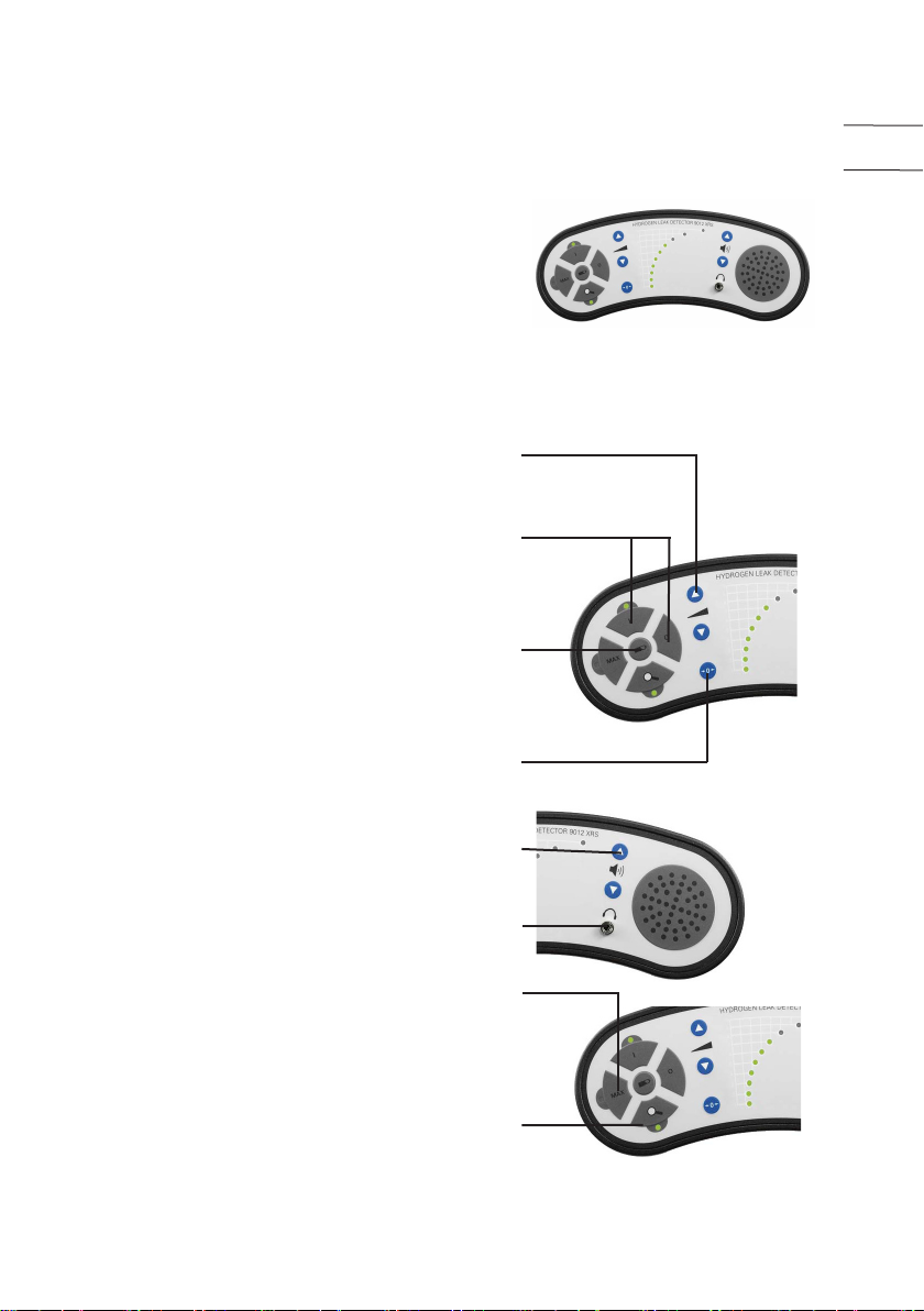
1.1 Function and controls
Following functions are controlled from the
panel:
- Sensitivity: can be varied in 10 steps, each
step doubles the sensitivity.
- On/Off: the detector has an automatic
switch-off aftr 30 minutes of no activity.
- Battery Check: At least 8 of the light emitting diods (LED) will illuminate at full
charge. Full charge takes one hour.
- Zero: the detector has an automatic zeroing function. The ZERO button allows the
operator to force the signal to zero instantaneously.
EN
- Sound level: the volume can be changed in
64 steps.
- Earphone output
- MAX: this is a peak-hold function allowing the operator to compare the maximum
gas signal in two different places.
- SEARCH (default): this is the normal
mode where the signal follows the gas concentration. The detector always starts in this
INFICON - Maintenance manual Sensistor XRS9012
Page 4
4
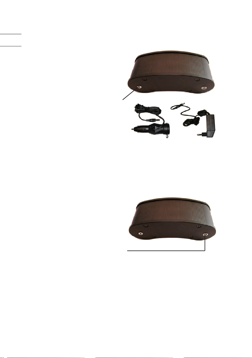
1.1.2 Battery charger
EN
The voltage range for charging is 9 15VDC. To operate on mains voltage
a voltage converter is connected to the
power input at the back of the unit.
There is also a possibility to connect
the unit to the car cigarettelighter,
which enables the unit to be charged
in the car.
1.1.3 Probe attachment
All probes are attached to the Leak
Detector Sensistor XRS9012 via cable
C21 to the socket at the back of the
unit.
INFICON - Maintenance manual Sensistor XRS9012
Page 5
5
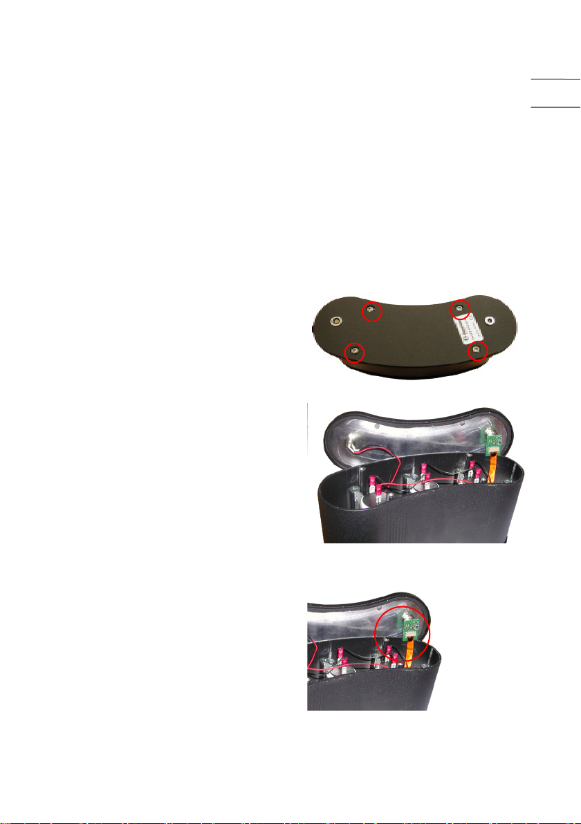
1.2 Changing batteries
Before reading this section, please
see picture on page 11 to get an overview of the assembly.
We recommend changing batteries
every three years (batteries will normaly last for several more years but
operation time is shortened).
Follow the procedure described
below. The batteries are placed inside
the Leak Detector.
Remove the four screws holding the
back cover
Remove the cover carefully
EN
Disconnect the exible cable
from the probe connector
circuit board (see next page)
INFICON - Maintenance manual Sensistor XRS9012
Page 6

6
1.2.1 Removing ex
EN
cable
Be very careful when removing the
exible cable in order not to demage
the rivet, the cable or the circuit
board. Read the whole section 1.2.1
before commencing work.
- First remove the rivet by carefully
pulling it upwards.
- Thereafter pull the holder the same
way.
Figure 1, Rivet and holder in place
Figure 2, Rivet is removed holder
still in place
Figure 1
Rivet
Holder
Flexible cable
Circuit board
Connector
Figure 2
Figure 3, Rivet and holder removed
Next step before pulling out the exible cable is opening the circuit board
Figure 3
connector (see next page).
INFICON - Maintenance manual Sensistor XRS9012
Page 7

7
To open the connector, pull the
locking mechanism away from the
connector body
Pull the cable straight out of the
connector
EN
Locking mechanism
Closed Open
The interior of the Leak Detector is
now accessible. It is now possible to
loosen the front cover.
INFICON - Maintenance manual Sensistor XRS9012
Page 8

8
1.2.2 Removing
EN
front cover
Remove the four front panel screws
from inside and the front cover carefully.
NB: the power supply cable from
the back cover is still attached to the
circuit board on the front cover
Diconnect the power supply cable
from its connector on the circuit
board
Front and back covers removed
INFICON - Maintenance manual Sensistor XRS9012
Page 9

9
Disconnect the cables attached to
the batteries, one battery at the time.
Remove the screws holding the bat-
tery (see gure).
NB: there are two screws holding
each battery.
Screw holding battery
Cables
EN
Replace the battery, connect the
cables and tighten the screw. Repeat
this for all three batteries
Re-assemble the Leak Detector
The new batteries should be charged
for >12 hours to be fully charged.
The Sensistor XRS9012 Leak
Detector is ready for use.
INFICON - Maintenance manual Sensistor XRS9012
Battery
Page 10

10
1.2.3 Replacing the
EN
circuit board
Open the detector following the
instruction in section 1.2
Loosen and remove the screws
holding the circuit board to the front
cover. Disconnect the speaker and
earphone connector. Lift the circuit
board carefully so that there is access
to the connector from the circuit
board to the touch pad panel. Loosen
the connector carefully. Replace the
circuit board.
Circuit board front side
Front cover without circuit board
Circuit board backside
INFICON - Maintenance manual Sensistor XRS9012
Page 11

11
1.3 Product
information
Touch pad keyboard
Front cover
Rubber seal
Loudspeaker
Circuit board
Battery
Battery holder
Front panel screw
Rubber seal
Back cover
EN
Serial number label
Product facts:
Sensitivity: 0,7ppm H2 in air
Response time: < 1sec
Start-up time: 6 sec
Outputs:
- Display 10 level LED bar
graph
- Speaker 5-1600 Hz
- Earphones std earphones, 3,5mm
jack, > 8ohm
Power Supply: Rechargeble lead
batteries
Battery capacity: 13h @ 20o C
Protection: IP55
Size & weight: 250x120x85 mm, 1,9kg
260x220x95 mm, 2,5 kg
(incl. carrying case)
INFICON - Maintenance manual Sensistor XRS9012
Page 12

12
1.4 Spare part list
EN
Part no.
Battery 591-294
Earphones 591-443
Carrying case 591-304
Charger AC (591-300) 591-301 SV, 591-302 USA, 591-303 UK
Charger car 591-361
Hand Probe H21 590-200
Cable C21 590-150
Circuit board 591-293
1.5 Function check
Action Result
Connect charger The instrument starts
Disconnect The instruments turns off
Change sensitivety The LED’s indicates corresponding sensitivity
Adjust the volume The volume should change
Press “Battery Check” button The LED should indicate Battery status
Disconnect Hand Probe The ON LED should ash red and an audio
signal appear
1.6 Sensitivity check
Action Result
Start XRS9012 The instruments starts and indicates sensitivity 5
Adjust the sensistivity to 10 The no. 10 LED is ashing
Apply 10ppm Hydrogen Signal should indicate: minimum LED 1
INFICON - Maintenance manual Sensistor XRS9012
Page 13

Page 14

www.inficon.com E-mail: reach.sweden@inficon.com
INFICON AB, Box 76, SE-581 02 Linköping, Sweden
Phone: +46 (0) 13 35 59 00 Fax: +46 (0) 13 35 59 01
 Loading...