

Page 1

Translation of the original operating instructions
XL3000flex
Leak Detector
jina83en1-03-(1809)
Catalog No.
520-200
From software version
V2.72
Page 2

INFICON GmbH
Bonner Strasse 498
50968 Cologne, Germany
Page 3

INFICON Table of Contents
XL3000flex-Operating-instructions-jina83en1-03-(1809) iii
Table of Contents
1 About these instructions ...................................................................................................................................6
1.1 Other associated documents ....................................................................................................................6
1.2 Target groups ...........................................................................................................................................6
1.3 Warnings...................................................................................................................................................6
2 Safety ...............................................................................................................................................................7
2.1 Intended use .............................................................................................................................................7
2.2 Owner requirements .................................................................................................................................7
2.3 Duties of the operator ...............................................................................................................................8
2.4 Dangers ....................................................................................................................................................8
3 Scope of delivery and additional equipment...................................................................................................10
3.1 Accessory list:.........................................................................................................................................10
4 Description......................................................................................................................................................12
4.1 Function ..................................................................................................................................................12
4.2 Operation mode sniffing..........................................................................................................................13
4.3 Device setup ...........................................................................................................................................14
4.4 Technical data ........................................................................................................................................18
4.5 Factory settings ......................................................................................................................................19
4.6 Sniffer line SL3000XL .............................................................................................................................22
4.6.1 Device overview.......................................................................................................................... 22
4.6.2 Operating elements on the handle.............................................................................................. 23
4.7 Touchscreen elements ...........................................................................................................................24
4.8 Elements of the error and warning display .............................................................................................27
5 Operation........................................................................................................................................................28
5.1 Switching the device on ..........................................................................................................................28
5.2 Basic settings..........................................................................................................................................28
5.2.1 Setting the language ...................................................................................................................28
5.2.2 Setting date and time ..................................................................................................................29
5.2.3 Selecting a unit for the leak rate ................................................................................................. 29
5.2.4 Select display unit for pressure................................................................................................... 30
5.2.5 Select interface unit for pressure ................................................................................................30
5.2.6 Operator types and authorizations.............................................................................................. 30
5.2.6.1 Logging out the operator ....................................................................................................31
Page 4

Table of Contents INFICON
iv XL3000flex-Operating-instructions-jina83en1-03-(1809)
5.2.7 Setting the audio alarm ...............................................................................................................32
5.2.8 Cathode Selection....................................................................................................................... 32
5.2.9 Changing the display of the axes................................................................................................ 33
5.2.10 Changing the display of measured values .................................................................................. 34
5.2.11 Displaying Calibration Instructions .............................................................................................. 34
5.2.12 Show calibration request............................................................................................................. 34
5.2.13 Show warnings............................................................................................................................ 34
5.2.14 Automatic switch-off of the touchscreen .....................................................................................35
5.2.15 Changing the display brightness ................................................................................................. 35
5.2.16 Show setpoint ............................................................................................................................. 35
5.2.17 Assigning favorite buttons ........................................................................................................... 35
5.2.18 Selecting the type of expansion module .....................................................................................36
5.2.19 Assigning inputs and outputs ...................................................................................................... 36
5.2.20 Assigning the digital inputs of the I/O module ............................................................................. 39
5.2.21 Assigning the digital outputs of the I/O module........................................................................... 42
5.2.22 Operation mode “Sniffing” ........................................................................................................... 44
5.3 Settings for the measurements...............................................................................................................45
5.3.1 Select gas type (mass) ............................................................................................................... 45
5.3.2 Setting setpoints ......................................................................................................................... 45
5.3.3 Calibrating the device ................................................................................................................. 46
5.3.3.1 Time and general preferences ...........................................................................................46
5.3.3.2 External Calibration Configuration and Start......................................................................47
5.3.3.3 External calibration with sniffer line SL3000XL ..................................................................49
5.3.3.4 Check the calibration..........................................................................................................49
5.3.3.5 Calibration using the external calibration leak test.............................................................50
5.3.3.6 Entering the calibration factor ............................................................................................50
5.3.3.7 Calibration factor sniffing....................................................................................................50
5.3.4 Suppressing gas backgrounds with "ZERO" functions ...............................................................51
5.4 Measuring ...............................................................................................................................................53
5.5 Measurement result display with signal filters ........................................................................................53
5.6 Recording data .......................................................................................................................................55
5.7 Copying measurement data, deleting measurement data ......................................................................56
5.8 Updating the software.............................................................................................................................56
5.8.1 Updating the software of the control unit .................................................................................... 56
5.8.2 Updating the software of the I/O module .................................................................................... 57
Page 5

INFICON Table of Contents
XL3000flex-Operating-instructions-jina83en1-03-(1809) v
5.9 Calling up information .............................................................................................................................58
5.10 Display, save, load parameters ..............................................................................................................61
5.11 Resetting the settings .............................................................................................................................62
6 Installation ......................................................................................................................................................63
6.1 Setup ......................................................................................................................................................63
6.2 IO module - or bus module mounting (optional) .....................................................................................64
7 Warning and error messages .........................................................................................................................66
8 Cleaning and maintenance.............................................................................................................................74
8.1 Cleaning the housing ..............................................................................................................................74
8.2 Maintenance of the XL3000flex ..............................................................................................................74
8.2.1 Change the filter mat of the fan input.......................................................................................... 74
8.2.2 Replacing the fuses .................................................................................................................... 75
8.2.3 Replacing the filter cartridge on the sniffer probe .......................................................................75
8.3 Sending for repair or maintenance .........................................................................................................77
9 Decommissioning the measuring instrument..................................................................................................78
9.1 Sending in the device .............................................................................................................................78
10 CE Declaration of Conformity .........................................................................................................................80
Index...............................................................................................................................................................81
Page 6
1 | About these instructions INFICON
6 / 84 XL3000flex-Operating-instructions-jina83en1-03-(1809)
1 About these instructions
This document applies to the software version stated on the title page.
Product names may occur in the document, which are added for identification
purposes only and belong to the respective owner of the rights.
1.1 Other associated documents
Interface protocols jira54
Bus module BM1000 jiqb10
I/O module IO1000 jiqc10
1.2 Target groups
These operating instructions are intended for the owner and for technically qualified
personnel with experience in leak detection technology and integration of leak
detection devices in leak detection systems. In addition, the installation and use of the
device require knowledge of electronic interfaces.
1.3 Warnings
DANGER
Imminent hazard resulting in death or serious injuries
WARNING
Hazardous situation resulting in potential death or serious injuries
CAUTION
Hazardous situation resulting in minor injuries
NOTICE
Hazardous situation resulting in damage to property or the environment
Page 7

INFICON Safety | 2
XL3000flex-Operating-instructions-jina83en1-03-(1809) 7 / 84
2 Safety
2.1 Intended use
The XL3000flex is a helium or hydrogen leak detector for sniffing detection. With the
device you locate and quantify leaks on test objects.
A test object always contains gas under overpressure. Check the exterior of the test
objects for escaping gas using a sniffer line (sniffing method).
• Operate the device only according to this instruction manual.
• Comply with application limits, see "Technical Data".
Improper use
Avoid the following, non-intended uses:
• Use outside the technical specifications, see "Technical Data".
• Use in radioactive areas
• Use of accessories or spare parts, which are not included in this manual.
• Test of wet or damp test objects
• Sniffing of explosive, aggressive, corrosive, flammable, toxic or reactive
substances
• Sniffing of condensable fluids and vapors
• Sniffing of gases contaminated with particles
• Sniffing gas mixtures with a hydrogen concentration greater than 5%
• Using the device in potentially explosive atmospheres.
• Aspirate liquids into the device via the sniffer line
• Operation at too high ambient temperature
• Searching mains voltage-carrying lines or objects with a sniffer line
• Use of the device as a seat or step
• When lifting the device using the handles, the feet of the device must not point
upwards. Otherwise your hands may get trapped.
• Inserting the sniffer tip into body orifices.
2.2 Owner requirements
The following notes are for companies or any person who is responsible for the safety
and effective use of the product by the user, employee or third party.
Safety conscious operation
• Operate the device only if it is in perfect technical condition and has no damage.
Page 8

2 | Safety INFICON
8 / 84 XL3000flex-Operating-instructions-jina83en1-03-(1809)
• Only operate the device in accordance with this instruction manual, in a safety and
risk conscious manner.
• Adhere to the following regulations and observe their compliance:
– Intended use
– General applicable safety and accident prevention regulations
– International, national and local standards and guidelines
– Additional device-related provisions and regulations
• Only use original parts or parts approved by the manufacturer.
• Keep this instruction manual available on site.
Personnel qualifications
• Only have qualified personnel make the basic settings on the device. The handling
of the sniffer line can also be done by laymen according to instructions.
2.3 Duties of the operator
• Read, observe, and follow the information in this manual and in the work
instructions provided by the owner. This concerns in particular the safety
instructions and warnings.
• Always observe the complete operating instructions for all work.
• If you have any questions about operation or maintenance that are not answered
in this manual, please contact Customer Service.
2.4 Dangers
The measuring instrument was built according to the state-of-the-art and the
recognized safety regulations. Nevertheless, improper use may result in risk to life and
limb on the part of the user or third parties, or damage to the measuring instrument or
other property may occur.
Hazards due to liquids
and chemicals
Liquids and chemical substances can damage the instrument.
• Comply with application limits, see "Technical Data".
• Do not suck up liquids with the instrument.
• Keep the hydrogen concentration below 5% to prevent ignition.
Dangers from electric
power
There is a danger to life from the contact of conductive parts inside the device.
• Disconnect the device from the power supply prior to any installation and
maintenance work. Make sure that the electric power supply cannot reconnected
without authorization.
The device contains electric components that can be damaged from high electric
voltage.
Page 9

INFICON Safety | 2
XL3000flex-Operating-instructions-jina83en1-03-(1809) 9 / 84
• Before connecting the device to the power supply, make sure that the supply
voltage specified on the device is the same as the local power supply.
Page 10

3 | Scope of delivery and additional equipment INFICON
10 / 84 XL3000flex-Operating-instructions-jina83en1-03-(1809)
3 Scope of delivery and additional
equipment
Item Quantity
XL3000flex 1
USB stick 1
Filter set for fans 2
Set of fuses 1
Power supply cable US 1
Power supply cable UK 1
Power supply cable JP 1
Power supply cable EU 1
Goods issue inspection log 1
Touch PIN 1
Operating instructions 1
►
Check the delivery contents after receiving the product to ensure it is complete.
Necessary accessories for operation
For operating the XL3000flex you need a sniffer line SL3000XL. It is available in
various lengths:
- SL3000XL XL, length 3 m, order number 521-011
- SL3000XL XL, length 5 m, order number 521-012
- SL3000XL XL, length 10 m, order number 521-013
- SL3000XL XL, length 15 m, order number 521-014
►
Always store the device in compliance with the technical data, see Technical data
[}18].
3.1 Accessory list:
The parts listed below can additionally be ordered.
Designation Catalog number
BM1000
Page 11

INFICON Scope of delivery and additional equipment | 3
XL3000flex-Operating-instructions-jina83en1-03-(1809) 11 / 84
Designation Catalog number
BM1000 PROFIBUS 560-315
BM1000 PROFINET IO 560-316
BM1000 DeviceNet 560-317
BM1000 EtherNet/IP 560-318
I/O1000 module, Analog/Digital 560-310
Data cable 0.5 m 560-334
Data cable 5m 560-335
Data cable 10 m 560-340
SL3000XL-3, 3m length 521-011
SL3000XL-5, 5m length 521-012
SL3000XL-10, 10m length 521-013
SL3000XL-15, 15m length 521-014
Adapter customer sniffer line P3000XL 521-015
Oil / Water Protection Tip for SL3000XL 521-016
Filter for Oil/Water Protection Tip 521-017
Sniffer tip ST312XL, 120 mm, rigid, 120 mm, rigid 521-018
Sniffer tip FT312XL, 120 mm, flexible, 120 mm, flexible 521-019
Sniffer tip ST385XL, 385 mm, rigid, 385 mm, rigid 521-020
Sniffer tip FT385XL, 385 mm, flexible, 385 mm, flexible 521-021
Sniffer tip FT250XL, 250 mm, flexible, 250 mm, flexible 521-022
Filter cartridge for SL3000XL (25x) 521-023
Page 12

4 | Description INFICON
12 / 84 XL3000flex-Operating-instructions-jina83en1-03-(1809)
4 Description
4.1 Function
The XL3000flex is a detection device for the tracer gases helium and hydrogen.
The device is designed for leak detection with the SL3000XL sniffer line, which is
available in different lengths. With this sniffer line, you can detect leaks at a greater
distance (high Flow) from the suspected leak if the detection limit has deteriorated and
switch to low flow for more accurate localization.
Digital data can be exchanged via the optionally available I/O module IO1000 or bus
module BM1000.
Page 13

INFICON Description | 4
XL3000flex-Operating-instructions-jina83en1-03-(1809) 13 / 84
4.2 Operation mode sniffing
The XL3000flex has been developed exclusively for the "sniffing" mode. For operating
you need a sniffer line SL3000XL. It is available in various lengths, see "Scope of
delivery and additional equipment [}10]".
The sniffer line SL3000XL is connected to the connection provided on the front of the
device, see "Device setup [}14]".
Sniffer line SL3000XL
SL3000XL
Detection limit < 2 x 10⁻⁷ mbar l/s
Gas flow (low flow / high flow) (300 sccm / 3000 sccm)
Available lengths 3 / 5 / 10 / 15 m
Cable sleeve Plastic
Good-Bad-DIsplay Yes
ZERO via button Yes
Connection on the device via a separate sleeve on
the front of the device
Display with measurement view Yes
Acknowledge faults via buttons on the sniffer probe Yes
End standby via a button on the sniffer probe Yes
Acknowledge calibration via a button on the sniffer
probe
Yes
Page 14

4 | Description INFICON
14 / 84 XL3000flex-Operating-instructions-jina83en1-03-(1809)
4.3 Device setup
Front view
1
2
3
4
5
6
1 Connection for sniffer line
SL3000XL
4 Speaker
2 Touchscreen 5 Connection for USB stick
3 Area for fixing a holder for the
sniffer line
6 Status LED
Page 15

INFICON Description | 4
XL3000flex-Operating-instructions-jina83en1-03-(1809) 15 / 84
Back view
1
2
3
4
5
6
7
1 Filter ventilator inlet 5 Power cable connection
2 Filter ventilator inlet 6 Mounting screws for a profile rail
(for mounting the I/O module
IO1000 or the bus module,
optional)
3 Device power ON/OFF switch 7 Connection for the data cable of
the I/O module or bus module
4 Electrical fuse
Page 16

4 | Description INFICON
16 / 84 XL3000flex-Operating-instructions-jina83en1-03-(1809)
View from below
1
2
1 filter fan outputs 2 Rubber feet (4 pieces)
Page 17

INFICON Description | 4
XL3000flex-Operating-instructions-jina83en1-03-(1809) 17 / 84
Side handles for transportation
1
1
1 Transport handles
Do not open the device!
Page 18

4 | Description INFICON
18 / 84 XL3000flex-Operating-instructions-jina83en1-03-(1809)
4.4 Technical data
Mechanical data
XL3000flex
Dimensions (L×W×H) 544 x 404 x 358 mm
Weight 37.5 kg
Electrical data
XL3000flex
Power 280 VA
Operating voltage 100 -120 VAC 50/60 Hz
230 VAC 50/60 Hz
Main fuse 2x T6,3 A 250 V
Ingress protection IP 30
Physical data
XL3000flex
Run-up time 150 s
Detectable gases Helium, hydrogen
Detectable masses
4
He, H2, Mass 3 (e.g. H-D, 3He or H3)
Ion source 2 longlife Iridium filaments, Yttrium-oxide
coated
Gas flow
1
• High flow
• Low flow
3000 sccm
300 sccm
Minimum detectable leak rate (MDLR)
• Helium
• High flow
• Low flow
• Forming gas (95/5)
• High flow
• Low flow
2 x 10⁻⁶ mbar l/s
2 x 10⁻⁷ mbar l/s
2 x 10⁻⁶ mbar l/s
2 x 10⁻⁷ mbar l/s
Response time
Page 19

INFICON Description | 4
XL3000flex-Operating-instructions-jina83en1-03-(1809) 19 / 84
XL3000flex
• High flow
• Low flow
< 1 s
< 1 s
1
Measured at 1 atm (1013 mbar) at sea level. The gas pressure changes with
atmospheric pressure and thus also with the geographical altitude.
Ambient conditions
XL3000flex
Permissible ambient temperature (during
operation)
10 °C ... 40 °C
Max. altitude above sea level 2000 m
Max. relative humidity above 40 °C 50%
Max. relative humidity from 31 °C to 40°C80% ... 50% (decreasing linearly)
Max. humidity up to 31 °C 80%
Storage temperature -20 °C ... 60 °C
Pollution degree 2
4.5 Factory settings
The following table shows the factory settings in the "Sniffing" mode.
Parameter Factory setting
AO upper limit exp. 1 x 10
-5
Operation mode XL Sniffer Adapter
Bus module address 126
Pressure capillary blocked
(Low Flow) 0.2 mbar
Pressure capillary broken
(Low Flow) 0.6 mbar
Clogged pressure capillary monitoring
- with XL Sniffer Adapter (High Flow) 150 mbar
Broken pressure capillary monitoring
- with XL Sniffer Adapter (High Flow) 400 mbar
Pressure unit (interface) mbar
Emission On
Filter leak rate threshold 1 x 10
-10
Page 20

4 | Description INFICON
20 / 84 XL3000flex-Operating-instructions-jina83en1-03-(1809)
Parameter Factory setting
Filter ZERO time 5 s
Filter mode I-Filter
Gas percentage in H2 (M3, He) 5 % H2 , 100 % M3, 100% He
Gas ballast Off
I/O module log ASCII
Calibration request On
Calibration factor VAC/SNIF Mx
(for vacuum, sniffing and all masses)
1.0
Cathode selection Auto Cat1
Compatibility mode XL Sniffer Adapter
Config. Analog output 1 Leak rate mantissa
Config. Analog output 2 Leak rate exponent
Config. Analog output scaling 0.5 V / decade
Configuration of digital outputs Pin 1: Trigger 1, inverted
Pin 2: Trigger 2, inverted
Pin 3: Trigger 3, inverted
Pin 4: Trigger 4, inverted
Pin 5: Ready
Pin 6: Error, inverted
Pin 7: CAL request, inverted
Pin 8: Open, inverted
Configuration of digital Inputs Pin 1: Select dyn. / normal CAL
Pin 2: Sniff
Pin 3: Start/Stop, inverted
Pin 4: ZERO
Pin 5: External CAL
Pin 6: Internal CAL
Pin 7: Clear
Pin 8: ZERO update
Pin 9: –
Pin 10: –
Leak rate unit SNIF, (display and
interface)
mbar l/s
Leak rate unit VAC, (display and
interface)
mbar l/s
Leak rate upper limit VAC (interface) 1.0 x 10
4
Leak rate lower limit VAC (interface) 1.0 x 10
-12
Leak rate upper limit SNIF (interface) 1.0 x 10
4
Leak rate lower limit SNIF (interface) 1.0 x 10
-8
Page 21

INFICON Description | 4
XL3000flex-Operating-instructions-jina83en1-03-(1809) 21 / 84
Parameter Factory setting
Fan mode Fan always on
Machine factor in standby Off
Machine factor / Sniff factor 1.0 (for all masses)
Mass 4
Module on the I/O connection IO1000
Nominal state TMP On
calibration leak external SNIF 9.9 x 10
-2
calibration leak external VAC 9.9 x 10
-2
calibration leak internal 9.9 x 10
-2
Open calibration leak internal Off
Sniffer line detection On
Sniffer LED Alarm Configured Flashing
Sniffer light brightness 5
Sniffer beep Trigger
Sniffer button Flow On
Sniffer key ZERO On
Language English
Muting the beep Off
TMP rotation speed 1000
Trigger level 1 (2, 3, 4) 2 x 10⁻⁴ mbar l/s
(1 x 10⁻⁵) mbar l/s
Preamplifier test at CAL On
Maintenance warning TMP and diaphragm pump
ZERO with start On
ZERO mode Suppress everything
Page 22

4 | Description INFICON
22 / 84 XL3000flex-Operating-instructions-jina83en1-03-(1809)
4.6 Sniffer line SL3000XL
4.6.1 Device overview
1
2
1 Connection SL3000XL, connection for
the sniffer line on the front
2 The status LED indicates the
operating status. A permanently lit
status LED shows that the sniffer line
is supplied with voltage.
Necessary accessories for operation
For operating the XL300flex you need the sniffer line SL3000XL. It is available in
different lengths (see Scope of delivery and additional equipment [}10]).
See also
2 Scope of delivery and additional equipment [}10]
Page 23

INFICON Description | 4
XL3000flex-Operating-instructions-jina83en1-03-(1809) 23 / 84
4.6.2 Operating elements on the handle
The display of the handle displays part of the information of the main display.
Fig.1:
Sniffer line SL3000XL
The leak rate is shown as a bar graph and displayed numerically. The unit of
measurement is the same as in the main display.
The display also shows the gas type and the tracer gas concentration. If the
XL3000flex is operated in the high flow operation mode, then the gas type display has
a dark background.
Warning or error messages are shown on the display. The message is confirmed with
the right button. The right button can otherwise be used to switch between low flow
and high flow.
The left button can be used for a ZERO-adjustment: The background display is set
toZERO by pressing the key.
The sniffer probe is equipped with LEDs for work in dimly lit places.
WARNING
Risk of eye damage
LEDs generate a bundled light that can damage your eyes.
► Do not look into the LEDs from a short distance or for longer periods of time.
Page 24

4 | Description INFICON
24 / 84 XL3000flex-Operating-instructions-jina83en1-03-(1809)
4.7 Touchscreen elements
1
2
3
4
5
6
7
1112
13
14
15
8
9
10
Fig.2:
Measurement display
1 Keyboard lock 2 Communication status 3 Operator
4 ZERO 5 Message 6 Tracer gas
7 Operation mode 8 Leak rate with peak hold
function
9 Graphic representation of the
leak rate and the peak hold
function
10 Time axis 11 Button "Favorite 2" 12 Button "Favorite 1"
13 Menu 14 Value axis 15 Value axis
1 - Keyboard lock
The control unit is locked or unlocked by pressing and holding the icon for the
keyboard lock.
2 - Icon for the communication status
• Icon connected: The device communicates with the mass spectrometer module.
Page 25

INFICON Description | 4
XL3000flex-Operating-instructions-jina83en1-03-(1809) 25 / 84
• Icon disconnected: The device does not communicate with the mass spectrometer
module.
Establish communication:
1
Reset control unit.
2
Checking the status of the mass spectrometer module.
3
Check cable connection.
3 - Operator
The registered operator is shown abbreviated.
Display Meaning
Ope Operator
Sup Supervisor
Int Integrator
Ser Service
4 - ZERO
Background suppression is active.
5 - Caution icon
Active warnings are stored in the unit.
The active warnings can be displayed via the menu "Info > History > Warnings".
6 - Tracer gas
Set tracer gas and tracer gas concentration percentage.
Display Meaning
He Helium (4He)
H2 Hydrogen
M3 E.g. H-D, 3He or H
3
7 - Operation mode
Configured operation mode
Display Operation mode
LOW FLOW XL sniffer adapter in LOW FLOW
HIGH FLOW XL sniffer adapter in HIGH FLOW
8 - Leak rate
Current measurement for the leak rate.
Page 26

4 | Description INFICON
26 / 84 XL3000flex-Operating-instructions-jina83en1-03-(1809)
9 - Graph
Graphic display of the leak rate Q(t).
10 - Leak rate
Time axis of the leak rate Q(t).
11 - Button "Favorite 2"
You can assign preferred parameters to this key.
12 - Button "Favorite 1"
You can assign preferred parameters to this key.
13 - Icon for the menu
All functions and parameters of the control unit can be accessed using the "Menu"
key .
A full representation of the menu is included on the supplied USB stick.
14 - Value axis
Value axis of the leak rate Q(t).
15 - Device of measurement
Device of measurement of the value axis.
Page 27

INFICON Description | 4
XL3000flex-Operating-instructions-jina83en1-03-(1809) 27 / 84
4.8 Elements of the error and warning display
Displayed
message
with details
Detailed display
further active
errors or
warnings
(if present)
To the display
further active
errors or
warnings
(if present)
WARNING
Number: 500
Pressure sensor not connected
(Value = 4.23E-2)
Further errors or warnings
To confirm
all messages
Information to
cause or remedy
to the message shown
above
501
502
Page 28

5 | Operation INFICON
28 / 84 XL3000flex-Operating-instructions-jina83en1-03-(1809)
5 Operation
5.1 Switching the device on
►
Turn on the XL3000flex via the power switch on the back of the device, see “Device
setup [}14]“.
ð The system is starting automatically.
ð After the start-up, the green LED on the front cover of the XL3000flex lights up.
5.2 Basic settings
The device is assembled and preconfigured so that basic settings have already been
made.
To check or change settings, first take a look at the factory defaults. See factory
settings of the XL3000flex (Factory settings [}19]).
5.2.1 Setting the language
Select the display language. The factory setting is English. (The display on the
handle of the SL3000XL sniffer line shows messages in English instead of in
Russian and Chinese.)
German
English
French
Italian
Spanish
Portuguese
Russian
Chinese
Japanese
Control unit Main Menu > Settings > Setup > Control unit >
Language
LD protocol Command 398
ASCII protocol *CONFig:LANG
Page 29

INFICON Operation | 5
XL3000flex-Operating-instructions-jina83en1-03-(1809) 29 / 84
5.2.2 Setting date and time
Setting the date
Format: DD.MM.YY
Control unit Main Menu > Settings > Date/Time > Date
LD protocol Command 450
ASCII protocol *HOUR:DATE
Setting the time
Format: hh: mm
Control unit Main Menu > Settings > Date/Time > Time
LD protocol Command 450
ASCII protocol *HOUR:TIME
5.2.3 Selecting a unit for the leak rate
Leak rate unit display
Selecting the leak rate unit in the display for vacuum sniff
0 mbar l/s (factory setting)
1 Pa m3/s
2 atm cc/s
3 Torr l/s
4 ppm
5 g/a
6 oz/yr
Control unit Main Menu > Display > Units (Display) > Leak Rate Unit SNIF
LD protocol Command 396 (sniffing)
ASCII protocol Command *CONFig:UNIT:SNDisplay
Leak rate unit interface
Selecting the leak rate unit of the interfaces for sniff
0 mbar l/s (factory setting)
1 Pa m3/s
2 atm cc/s
3 Torr l/s
4 ppm
5 g/a
6 oz/yr
Page 30

5 | Operation INFICON
30 / 84 XL3000flex-Operating-instructions-jina83en1-03-(1809)
Control unit Settings > Set up > Interfaces > Units (interface) > Leak rate unit
SNIF
LD protocol Command 432 (sniffing)
ASCII protocol Command *CONFig:UNIT:LRSnif
5.2.4 Select display unit for pressure
Device of pressure
mbar
Pa
atm
Torr
Control unit Main menu > Display > Units (display) > Pressure unit
5.2.5 Select interface unit for pressure
Pressure unit
interface
Selecting the pressure device of the interfaces
0 mbar (factory setting)
1 Pa
2 atm
3 Torr
Control unit Main Menu > Settings > Setup > Interfaces > Units (Interface) >
Pressure Unit
LD protocol Command 430 (sniffing)
ASCII protocol Command *CONFig:UNIT:Pressure
5.2.6 Operator types and authorizations
There are four different operator types that are distinguished by different
authorizations. The integrator is registered ex works.
Additional operators can be registered. The following table shows options for
individual operator types to register new operator types.
Operator registration
Viewer Operator Supervisor Integrator
- Operator
Viewer
Supervisor
Operator
Viewer
Integrator
Supervisor
Operator
Page 31

INFICON Operation | 5
XL3000flex-Operating-instructions-jina83en1-03-(1809) 31 / 84
Viewer Operator Supervisor Integrator
Viewer
For the types "Integrator", "Supervisor" and "Operator", a four-digit PIN must be
assigned during registration (0000 ... 9999). "0000" is assigned to all operators ex
works.
If an operator keeps the pin "0000", this operator will always be registered is during
the start up of the system (without PIN query).
A key-operated switch can be used in addition to a PIN if an I/O module is connected.
The key-operated switch is connected to the I/O module via three digital inputs (see
operating instructions of the LDS3000).
The following table shows the authorizations of individual operator types.
Function Viewer Operator Supervisor Integrator
Changing parameters - x x x
Changing the display
of error information
- x x x
Calling up factory
settings
- - - x
Entering
maintenance history
- - - x
The menu "Service" is accessible only to INFICON service staff.
Display error
information
The type of error information can be set differently for each operator type. The
Integrator always receives the complete information.
Number: Message number
text: Brief description
Info: Expanded message information
• Only numbers
• Number and text
• Number, text and info
Control unit Main Menu > Functions > Data >
Parameter > Error info Viewer (Operator,
Supervisor)
5.2.6.1 Logging out the operator
The operator activates access level "Viewer" to log out. "Access Ctrl > Viewer"
Page 32
5 | Operation INFICON
32 / 84 XL3000flex-Operating-instructions-jina83en1-03-(1809)
5.2.7 Setting the audio alarm
WARNING
Damage to the hearing due to loud audio
The alarm level of the device can exceed 85 dB(A).
► Adjust the volume accordingly.
► Only expose yourself a short time to the alarm.
► Use hearing protection.
Volume of the headphones or active speaker
--- No sound
Proportional: The frequency of the audible signal is proportional to the bar graph
display or diagram height. The frequency range is 300 Hz to 3300 Hz.
Setpoint: The pitch is proportional to the leak rate. The signal sounds if the leak rate
exceeds the selected trigger value.
Pinpoint: The sound of the acoustic signal changes its frequency within a specific
range of leak rates. Range: A decade below the selected trigger threshold up to one
decade above. The sound keeps at a constant low and a constant high frequency
below and above this range, respectively.
Trigger: If the selected trigger threshold is exceeded, a two-pitch signal sounds.
Control unit Main menu > Settings > Set up > Control unit > Audio > Audio
alarm mode
Behavior with warnings or error messages:
If the touch screen shows a warning or an
error, then a two-pitch signal sounds simultaneously.
5.2.8 Cathode Selection
Selecting a cathode
The mass spectrometer includes two cathodes. In the factory setting the device uses
cathode 1. If it is defective, the device automatically switches to the other cathode.
With this setting it is possible to select a certain cathode.
0 CAT1
1 CAT2
2 Auto Cat1 (automatic switching to cathode 2, factory setting)
3 Auto Cat2 (automatic switching to cathode 1)
4 OFF
Page 33

INFICON Operation | 5
XL3000flex-Operating-instructions-jina83en1-03-(1809) 33 / 84
Control unit Main menu > Settings > Set up > MS module > Ion source >
Cathode selection
LD protocol 530
ASCII protocol *CONFig:CAThode *STATus:CAThode
5.2.9 Changing the display of the axes
The touchscreen grays out the parameters if
• the user is not authorized to modify the values,
• the older version of the software run by mass spectrometer module LDS3000 does
not support this parameter.
Scaling of the Q(t)axis
Linear or logarithmic
Lin.
Log.
Control unit Main menu > Display > Q(t) axis > Linear or logarithmic
Number of decades with logarithmic view
1
2
3
4
Control unit Main menu > Display > Q(t) axis > Decades
Autoscale
Off
On
Control unit Main menu > Display > Q(t) axis > Automatic scaling
Scaling of the time axis
Scaling of the time axis
15 s
30 s
60 s
120 s
240 s
480 s
960 s
Control unit Display > Time axis > Time axis scale
Page 34

5 | Operation INFICON
34 / 84 XL3000flex-Operating-instructions-jina83en1-03-(1809)
5.2.10 Changing the display of measured values
Measured value
display
Type of graphic display
Line graph
Bar graph
Control unit Main menu > Display > Measurement display > Measured
view
Numeric representation of the measurements
Off
On
Control unit Main menu > Display > Measurement display > Measured
view
5.2.11 Displaying Calibration Instructions
Suppress or allow the calibration note with the following content:
• Leak rate of the applied calibration leak
• No calibration should take place during the first 20 mins
OFF (suppressed)
ON (allowed)
Control unit Main menu > Settings > Set up > Control unit > Messages >
Displaying Calibration Instructions
5.2.12 Show calibration request
The calibration request can be allowed or suppressed.
OFF (suppressed)
ON (allowed)
Control unit Settings > Set up > Control unit > Messages > Show
calibration request
5.2.13 Show warnings
Warnings and error messages can be displayed on the touch screen.
Page 35

INFICON Operation | 5
XL3000flex-Operating-instructions-jina83en1-03-(1809) 35 / 84
Off
On
Control unit Main menu > Settings > Set up > Control unit > Messages >
Show warnings
5.2.14 Automatic switch-off of the touchscreen
The touch screen can be switched off automatically after a specific time without any
operation to save energy.
30 s
1 min
2 min
5 min
10 min
30 min
1 h
∞ (=never)
Control unit Main menu >Settings > Set up > Control unit > Energy >
Display off after
5.2.15 Changing the display brightness
Display brightness
20 ... 100%
Control unit Main menu > Display > Brightness > Display brightness
5.2.16 Show setpoint
Selection of the trigger (leak rate threshold) displayed on the touchscreen.
1
2
3
4
Control unit Main menu > Settings > Trigger > Trigger sel.
5.2.17 Assigning favorite buttons
The favorite buttons offer direct access to individual functions. They can be assigned
with access control "Supervisor" or higher by the user.
Favorite 1: Center button
Page 36

5 | Operation INFICON
36 / 84 XL3000flex-Operating-instructions-jina83en1-03-(1809)
Favorite 2: Right button
Favorite 3: Button at the bottom right of the main menu.
CAL
ZERO
Measurement view
Start/Stop
View settings
Volume
- - - (= without function)
Check CAL
Flow switching
Control unit Main menu > Settings > Favorites > Favorite 1 (2, 3)
5.2.18 Selecting the type of expansion module
Selecting the
expansion module
Selecting the type of module connected to the I/O connection
I/O module
Bus module
Control unit Main Menu > Settings > Setup > Interfaces > Device select. >
Module on I/O connection
or
Main Menu > Settings > Setup > Accessories > Device select. >
Module on I/O connection
LD protocol –
ASCII protocol –
5.2.19 Assigning inputs and outputs
Assigning analog
outputs of the I/O
module
The analog outputs of I/O module IO1000 can with assigned with different
measurement value displays.
Possible functions: see the following table
Control unit Main Menu > Settings > Set up > Interfaces > I/O module >
Analog outp. > Config. Analog outputs 1/2
LD protocol Commands 222, 223, 224
ASCII protocol Command *CONFig:RECorder:LINK1
Command *CONFig:RECorder:LINK2
Command *CONFig:RECorder:SCALE
Command *CONFig:RECorder:UPPEREXP
Limit values can be defined for the output voltages.
Page 37

INFICON Operation | 5
XL3000flex-Operating-instructions-jina83en1-03-(1809) 37 / 84
SNIF: Min. 1 x 10⁻⁹...1 x 10-1 mbar l/s
Max. 1 x 10⁻⁸...1 x 10-1 mbar l/s
Control unit Main Menu > Settings > Set up > Interfaces > LR limits
LD protocol Command 227 (Snif)
ASCII protocol Command *CONFig:LIMITS:SNIF
Functions, assignment of analog outputs:
Off The analog outputs are switched off
(Output voltage = 0 V).
Pressure p1 / Pressure p2 1 ... 10 V; 0.5 V / decade;
1 V = 1 x 10⁻³ mbar
Leak rate mantissa 1 ... 10 V; linear; in the selected unit Useful only if the other analog
output is assigned "Leak rate
exponent".
Leak rate exponent 1 ... 10 V; 0.5 V / decade;
Step function;
1 V = 1 x 10
-12
; in selected unit
Useful only if the other analog
output is assigned “Leak rate
mantissa” or “Leak rate ma. Hys."
is occupied.
Linear leak rate x... 10 V; linear;
in the selected unit
The upper limit (= 10 V) is set via the parameter "Upper limit exponent". The lower value is always 0 (leak
rate), which corresponds to 0 V output voltage. The exponent of the upper limit can be set in entire decades,
such as 1x10⁻⁴ mbarl/s.
Settings > Set up > Interfaces > I/O module > Analog scale > AO exponent upper limit.
This setting is for both analog outputs, if an appropriate output function is selected. Depending on the selected
leak rate unit there is a different absolute limit.
The selected range can be additionally narrowed by the limits, which is valid for all interfaces, see above.
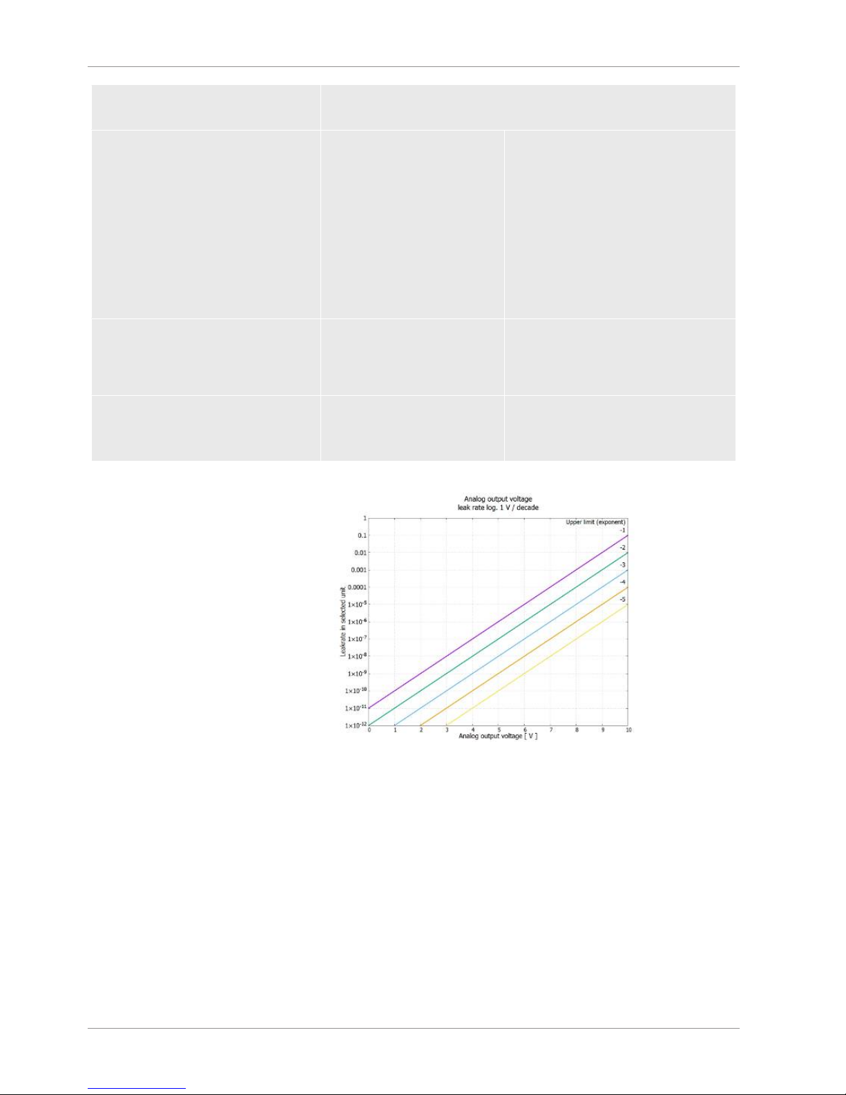
Leak rate log. x... 10 V; logarithmic;
in the selected unit
The upper limit (= 10 V) and the scale (V / decades) are set via the parameters "Upper limit exponent" and
"Scale for leak rate". For example:
Upper limit set to 1x10⁻⁵mbarl/s (=10 V). Scale set to 5 V / decade. Lower limit is at 1x10⁻⁷mbarl/s (=0 V).
The logarithmic output function of both the slope in V / decade as well as the upper limit (10 V limit) can be set.
This results in the minimum displayable value. The following slopes are available: 0.5, 1, 2, 2.5, 3, 5, 10 V/The
higher the selected slope value, the smaller the displayable area. The logarithmic settings are the most useful
when several decades can be displayed, so a setting of <10 V / decade. The upper limit is the same for both
analog outputs. In both of the following figures the 1 V / decade and 5 V / decade with different upper limit
settings are exemplified. Depending on the selected leak rate unit there is a different absolute limit. The
selected range can be additionally narrowed by the limits, which is valid for all interfaces, see above.
Page 38
5 | Operation INFICON
38 / 84 XL3000flex-Operating-instructions-jina83en1-03-(1809)
Set by interface The output voltage can be specified for tests with the LD log command
221.
Leak rate Ma. Hys. 0.7 ... 10 V; linear;
in the selected unit
Useful only if the other analog output
is assigned "Leak rate exponent".
Through an overlap of the mantissa in
the range 0.7 to 1.0, a constant
jumping between two decades is
prevented. 0.7 V corresponds to a
leak rate of 0.7 x 10-x. 9.9 V
corresponds to a leak rate of 9.9 x 10
-
x
.
Pressure p1 (1 V / Dec.)/
Pressure p2 (1 V / Dec.)
1 ... 10 V; 1 V / decade;
2.5 V = 1 x 10⁻³ mbar;
8.5 V = 1000 mbar
Leak rate log. H./
Leak rate exp. Inv.
Special function. Use only on
the recommendation of
INFICON.
Page 39

INFICON Operation | 5
XL3000flex-Operating-instructions-jina83en1-03-(1809) 39 / 84
5.2.20 Assigning the digital inputs of the I/O module
The digital inputs PLC-IN 1 ... The available functions can be assigned in any way
necessary to the 10 I/O module.
– Active signal: typically 24 V
– Inactive signal: typically 0 V.
The 24V output of the I/O module can be used as an active signal.
Every function can be inverted.
Possible functions: see the following table
Control unit Settings > Set up > Interfaces > I/O module > Digital inputs >
Configuration PLC Input
LD protocol Command 438
ASCII protocol *CONFig:PLCINLINK:1 (2 ... 10)
Key-operated switch
An external key switch with up to three switching outputs can be connected via three
PLC inputs. The key switch can be used to select the access level of the operator of
the control unit.
Button 1 - Operator
Button 2 - Supervisor
Button 3 - Integrator
Example for a suitable key switch: Hopt+Schuler, No. 444-05
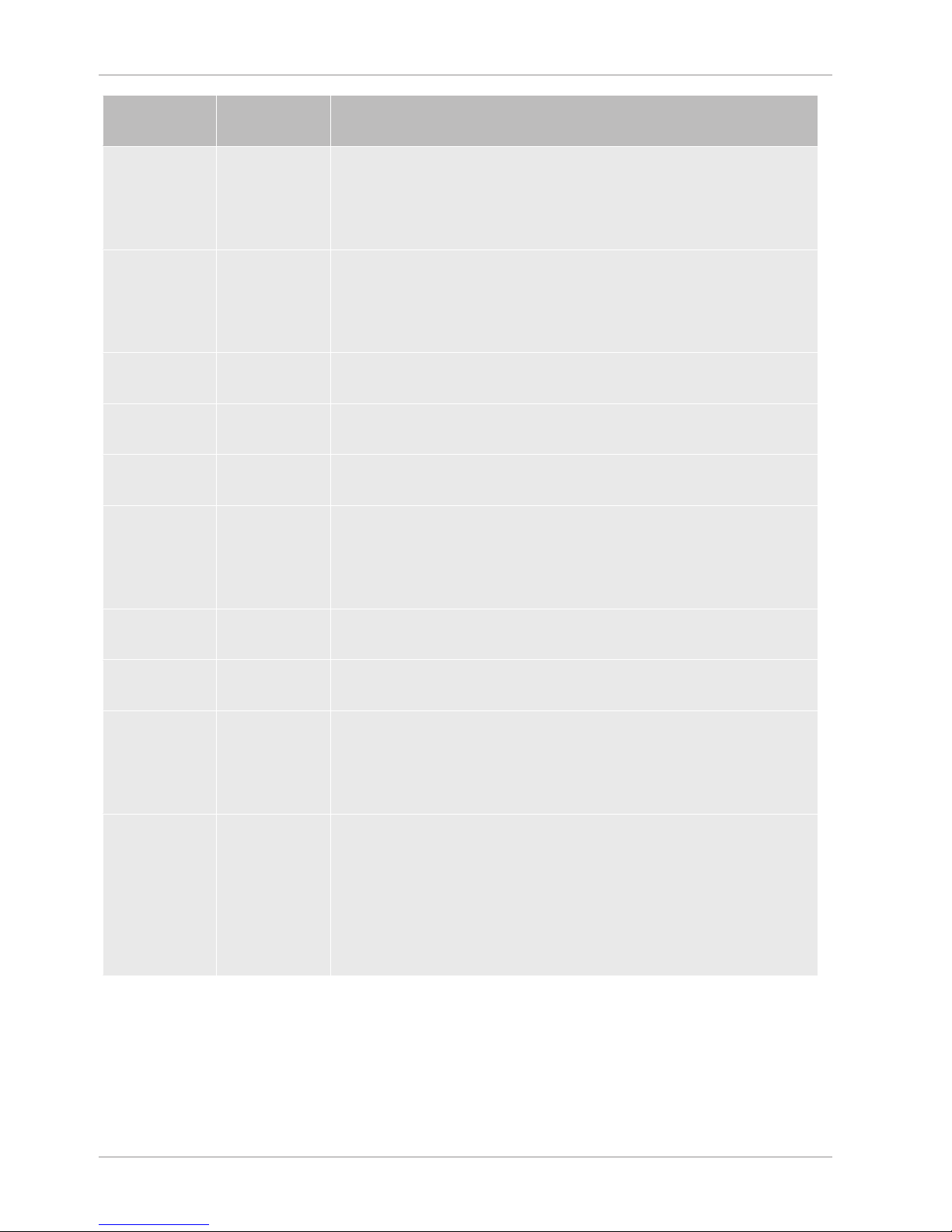
Functions, assignment of digital inputs:
Function Flank/state: Description
No function – No function
Page 40
5 | Operation INFICON
40 / 84 XL3000flex-Operating-instructions-jina83en1-03-(1809)
Function Flank/state: Description
CAL dynam. inactive→
active:
active→
inactive:
Start external dynamic calibration.
Apply value for background and finish calibration.
CAL external inactive→
active:
active→
inactive:
Start external calibration.
Apply value for background and finish calibration.
SNIF/VAC inactive→
active:
Enable sniffer mode.
Start inactive→
active:
Switch to Meas. (ZERO is possible, all trigger outputs switch depending
on the leak rate.)
Stop inactive→
active:
Switch to Standby. (ZERO is not possible, all trigger outputs will return
"Leak rate threshold value exceeded".)
ZERO inactive→
active:
active→
inactive:
Switch ZERO on.
Switch ZERO off.
ZERO pulse inactive→
active:
Switching ZERO on or off.
Delete inactive→
active:
Erase warning or error message / cancel calibration.
Gas ballast inactive→
active:
active→
inactive:
Open gas ballast valve.
Close gas ballast valve unless always open.
Selection dyn/
norm
inactive→
active:
active→
inactive:
External calibration mode with activation of digital input "CAL":
External dynamic calibration (without auto tune, allowing for the
measuring times and pump cycle times set via the digital inputs)
External normal calibration (with auto tune, not considering the system-
specific measuring times and pump cycle times)
Page 41

INFICON Operation | 5
XL3000flex-Operating-instructions-jina83en1-03-(1809) 41 / 84
Function Flank/state: Description
Start / Stop inactive→
active:
active→
inactive:
Switch to Meas. (ZERO is possible, all trigger outputs switch depending
on the leak rate.)
Switch to Standby. (ZERO is not possible, all trigger outputs will return
"Fail".)
Key 1 active: User "Operator"
Key 2 active: User "Supervisor"
Key 3 active: User "Integrator"
CAL inactive→
active:
When set to Meas, the device will start an external calibration.
ZERO update inactive→
active:
A new zero word is formed.
XL flow inactive→
active:
active→
inactive:
The XL flow is turned on with the XL Adapter.
The XL flow is turned off with the XL Adapter.
CAL Mach inactive→
active:
Start machine factor calibration
Internal PROOF inactive→
active:
Start the internal Proof function.
External
PROOF
inactive→
active:
Start the external Proof function.
START / STOP
impulse
inactive→
active:
Activate Start or Stop.
ZERO updated inactive→
active:
active→
inactive:
Update or switch on ZERO
No function
Flow inactive→
active:
active→
inactive:
Switch flow of SL3000XL to 3000 sccm (XL adapter)
Switch flow of SL3000XL to 300 sccm (XL adapter)
CAL machine inactive→
active:
Determining the machine factor or of the sniff factor
External CAL
check
inactive→
active:
Check calibration with external calibration leak
Page 42

5 | Operation INFICON
42 / 84 XL3000flex-Operating-instructions-jina83en1-03-(1809)
Function Flank/state: Description
Start / Stop
impulse
inactive→
active:
Switching between measuring operation and standby
Mass 2 / Mass4inactive→
active:
active→
inactive:
Activate mass 4
Activate mass 2
5.2.21 Assigning the digital outputs of the I/O module
The digital outputs PLC-OUT 1 ... The available functions can be assigned in any
way necessary to the 8 I/O module.
Every function can be inverted.
Possible functions: see the following table
Control unit Settings > Set up > Interfaces > I/O module > Digital outputs >
Configuration PLC Output
LD protocol Command 263
ASCII protocol *CONFig:PLCOUTLINK:1 (2 ... 8)
Functions, assignment of digital outputs:
Function State: Description
Open open: always open
Trigger 1 closed:
open:
Value exceeded leak rate threshold Trigger 1
Value fell below leak rate threshold Trigger 1
Trigger 2 closed:
open:
Value exceeded leak rate threshold Trigger 2
Value fell below leak rate threshold Trigger 2
Trigger 3 closed:
open:
Value exceeded leak rate threshold Trigger 3
Value fell below leak rate threshold Trigger 3
Trigger 4 closed:
open:
Value exceeded leak rate threshold Trigger 4
Value fell below leak rate threshold Trigger 4
Ready closed:
open:
Emission switched on, calibration process inactive, no error
Emission switched off or calibration process active or error
Warning closed:
open:
Warning
no warning
Error closed:
open:
Error
no error
Page 43

INFICON Operation | 5
XL3000flex-Operating-instructions-jina83en1-03-(1809) 43 / 84
Function State: Description
CAL active closed:
open:
Device is to be calibrated.
Device is not to be calibrated.
CAL request closed:
closed:
open:
and no external calibration: Calibration request (with temperature change from
5°C or 30 minutes after the start-up or if default rotation speed was changed)
and external calibration or "CAL check": Request "Open or close external
calibration leak"
no request
Run-up closed:
open:
Run-up
no run-up
ZERO active closed:
open:
ZERO switched on
ZERO switched off
Emission on closed:
open:
Emission switched on
Emission switched off
Measuring closed:
open:
Measuring (ZERO is possible, all trigger outputs switch depending on the leak
rate.)
Standby or emission disabled (ZERO is not possible, all trigger outputs will
return "Leak rate threshold value exceeded".)
Standby closed:
open:
Standby (ZERO is not possible, all trigger outputs will return “Leak rate
threshold value exceeded”.)
Measuring (ZERO is possible, all trigger outputs switch depending on the leak
rate.)
SNIF closed:
open:
SNIF
VAC
Error or
warning
closed:
open:
Error or warning
No error or warning
Gas ballast closed:
open:
Gas ballast is active
Gas ballast is inactive
Calibration
leak open
closed:
open:
calibration leak is active
calibration leak is inactive
CAL stable closed:
open:
Calibration completed with calibration leak (see "Time and general
preferences")
Assignment not stable or calibration is inactive
Page 44

5 | Operation INFICON
44 / 84 XL3000flex-Operating-instructions-jina83en1-03-(1809)
Function State: Description
Cathode 2 closed:
open:
Cathode 2 is active
Cathode 1 is active
5.2.22 Operation mode “Sniffing”
The device has the sniffer mode with a high flow rate.
For the XL3000flex , only this operation mode makes sense.
Select operation mode
0
1
2
(Not applicable for XL3000flex!)
(Not applicable for XL3000flex!)
Operation mode XL sniffer adapter
Control unit Sniffer mode:
Main Menu > Functions > Start/Stop
LD protocol Command 401
ASCII protocol Command *CONFig:MODE
Page 45

INFICON Operation | 5
XL3000flex-Operating-instructions-jina83en1-03-(1809) 45 / 84
5.3 Settings for the measurements
5.3.1 Select gas type (mass)
The machine, calibration and sniff factor are dependent on the configured mass and
are saved in the mass spectrometer module.
2
3
4
H2 (Hydrogen, forming gas)
3
He or deuterated hydrogen (HD)
4
He (Helium) (factory setting)
Control unit Main menu > Settings > Mass
LD protocol Command 506 with value 2 (3, 4)
ASCII protocol Command *CONFig:MASS 2 (3, 4)
5.3.2 Setting setpoints
You can set the leak rate for the setpoint to 1, 2, 3 and 4 separately.
When the setpoints are exceeded:
• If the setpoint 1 or 2 is exceeded, the measurement line in the measurement
window changes color.
• The setpoint relay of the digital output switches, see also "Assigning the digital
outputs of the I/O module [}42]" or the interface description.
Also setpoint 1 defines the trigger point for the different alarms, see also "Change
audio settings".
ü
Operator
or
Supervisor
rights
1
> Trigger
2
Set up.
3
Save .
Page 46

5 | Operation INFICON
46 / 84 XL3000flex-Operating-instructions-jina83en1-03-(1809)
5.3.3 Calibrating the device
5.3.3.1 Time and general preferences
NOTICE
Incorrect calibration because of operating temperature that is too low
If the instrument is calibrated immediately after power-on, it may provide incorrect
measurement results.
► For optimum accuracy the device should have been turned on at least 20 minutes
previously.
The device only needs to be calibrated once per shift for the desired gas. Thereafter
you can switch between the different flows without re-calibrating.
Calibration is also required after the following actions:
• Sniffer line replacement
• Filter change of the sniffer line
• Prompt for calibration by the system
Switching off the
preamplifier test
The device tests the installed preamplifier during calibration. You can switch off of
the amplifier test. This increases the speed of the calibration, but reliability drops off.
0 OFF
1 ON
Control unit Main Menu > Settings > Set-up> MS-module > Preamplifier
> Test > Preamplifier test with CAL
LD protocol Command 370
ASCII protocol Command *CONFig:AMPTest (ON,OFF)
Enabling calibration
request
If Calibration request is enabled, the device will prompt the operator to perform a
calibration 30 minutes after it has been switched on and in case of temperature
changes greater than 5°C.
0 OFF
1 ON
Control unit Main Menu > Functions > CAL > Settings > CAL request. >
Calibration request
Page 47

INFICON Operation | 5
XL3000flex-Operating-instructions-jina83en1-03-(1809) 47 / 84
or
Main Menu > Settings > Set-up> CAL request. > Calibration
request
LD protocol Command 419
ASCII protocol *CONFig:CALREQ (ON,OFF)
Calibration warning
Wrn650
The warning message Wrn650 "Calibration within the first 20 minutes is not
recommended" can be allowed or suppressed.
0 OFF (suppressed)
1 ON (allowed)
Control unit Functions > CAL > Settings > CAL request. > Calibration
warning W650
or
Settings > Set-up> CAL request. > Calibration warning
W650
LD protocol Command 429
ASCII protocol *CONFig:CALWarn ON (OFF)
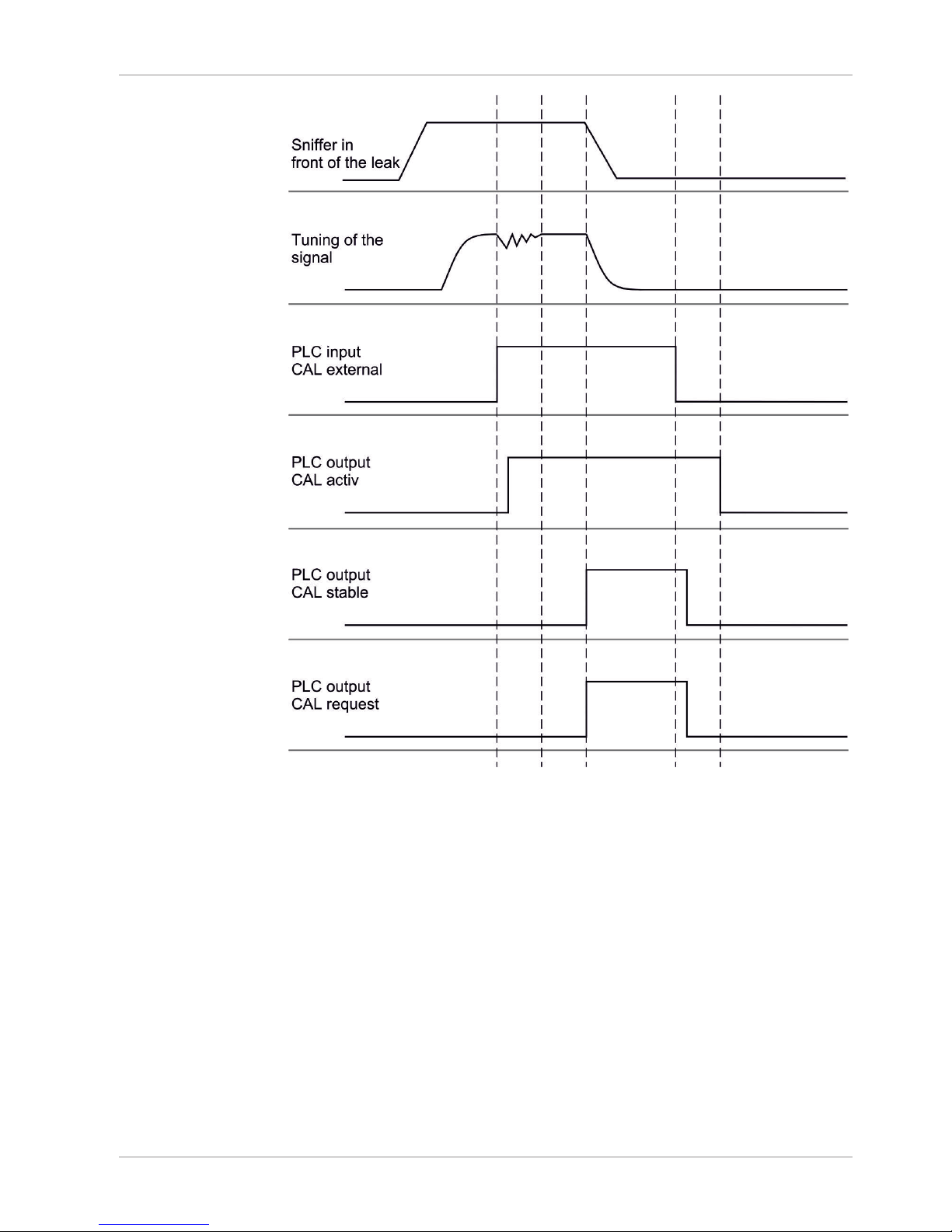
5.3.3.2 External Calibration Configuration and Start
Prerequisite for the calibration with the internal calibration leak is the one-time entry of
the leak rate of the calibration leak.
In Sniffer mode, sniffing with the sniffer line is always performed on the open
calibration leak.
Leak rate of external
calibration leak sniffing
Define the leak rate of the calibration leak you wish to use during calibration.
Calibration will not be possible unless you enter the value here.
A specific leak rate must be set for each gas (mass).
Control unit Main Menu > Settings > Set up > Operation modes > Sniffing
> Ext. calibration leak > Mass 2 (3, 4)
or
Main menu > Functions > CAL > Settings > Ext. calibration
leak (for current mass in selected unit)
LD protocol Command 392
ASCII protocol Command *CONFig:CALleak:EXTSniff (for current mass in
device selected unit)
Page 48

5 | Operation INFICON
48 / 84 XL3000flex-Operating-instructions-jina83en1-03-(1809)
► LD and ASCII protocol: The status must be queried via: Command 260 or
*STATus:CAL
1
Start calibration.
2
Wait until leak rate signal is tuned and stable.
3
Start calibration:
Control unit: Features > CAL > Extern
LD protocol: 4, Parameter 1
ASCII protocol: *CAL:EXT
IO1000: see the figure below.
ð Request to "close calibration leak"
4
Sniffer mode: Remove sniffer line from calibration leak.
ð Leak rate signal decreases.
5
Confirm measured background value is stable:
Control unit: "OK"
LD protocol: 11, Parameter 1
ASCII protocol: *CAL:CLOSED
IO1000 see the figure below.
ð Calibration is completed if:
Control unit: Old and new calibration factor are displayed
LD protocol LD instruction 260 provides 0 (READY)
ASCII protocol: Command *STATus:CAL? provides IDLE
IO1000 see the figure below.
Page 49
INFICON Operation | 5
XL3000flex-Operating-instructions-jina83en1-03-(1809) 49 / 84
Fig.3:
External calibration with IO1000 using the example of sniffer line SL3000XL, description
of PLC inputs and outputs: "Assigning inputs and outputs [}36]"
5.3.3.3 External calibration with sniffer line SL3000XL
Low flow and high flow must be calibrated separately.
To ensure optimal calibration with hydrogen or forming gas for low flow and high flow,
the calibration leak must meet the following requirements:
– 100 % H2: LR > 1 x 10
-4
– Forming gas (95/5): LR > 2 x 10
-3
For calibration, we recommend our calibration leak with catalog number 12322.
5.3.3.4 Check the calibration
To check whether a re-calibration is necessary, check the already existing.
Page 50

5 | Operation INFICON
50 / 84 XL3000flex-Operating-instructions-jina83en1-03-(1809)
5.3.3.5 Calibration using the external calibration leak test
► LD and ASCII protocol: The status must be queried via: Command 260 or
*STATus:CAL
1
Hold the sniffer line to the test leak.
2
Wait until leak rate signal is tuned and stable.
3
Start test:
Control unit: Functions > CAL > Test ext.
LD protocol: 4, Parameter 5
ASCII protocol: *CAL:PROOFEXT
IO1000 compare figure in "External Calibration Configuration and Start".
ð Request to "close calibration leak"
4
Sniffer mode: Remove sniffer line from calibration leak.
ð Leak rate signal decreases.
5
Confirm measured background value is stable:
Control unit: "OK"
LD protocol: 11, Parameter 1
ASCII protocol: *CAL:CLOSED
IO1000 compare figure in "External Calibration Configuration and Start".
ð Test is completed if:
Control unit: Result is displayed
LD protocol: As with the other steps, the status must be queried
ASCII protocol: As with the other steps, the status must be queried
IO1000 compare figure in "External Calibration Configuration and Start".
5.3.3.6 Entering the calibration factor
The calibration is usually determined by the appropriate calibration routine. Therefore,
it is usually not necessary to adjust the calibration factor manually.
An incorrectly set calibration inevitably leads to wrong leak rate indicator!
5.3.3.7 Calibration factor sniffing
Entry of the calibration factors for masses
2, 3, 4 in low flow and in high flow.
The values will be overwritten during the
next calibration.
"High Flow-" or XL settings are available
only in operation mode "XL Sniffer
Adapter".
Page 51

INFICON Operation | 5
XL3000flex-Operating-instructions-jina83en1-03-(1809) 51 / 84
The calibration factors are managed
separately to earth and to "High Flow"
and "Low Flow".
0.01 … 100
Control unit Main Menu > Settings > Set up > Operation modes > SNIF >
Calibration factor
Mass Calibration factor SNIF
2 H2
3 M3
4 He
2XL XL H2
3XL XL M3
4XL XL He
LD protocol Commands 519, 521
ASCII protocol Command *FACtor:CALSniff or *FACtor:CALSXL for the
current mass
5.3.4 Suppressing gas backgrounds with "ZERO" functions
Unwanted sample gases can be suppressed with ZERO. If ZERO is enabled, the
currently measured leak rate value will be interpreted as carrier gas and subtracted
from all subsequently measured values. The background value suppressed by ZERO
is adjusted automatically if the background changes inside the device. The
background value is automatically adjusted depending on the set ZERO time, except
for filter setting I•CAL, see "Measurement result display with signal filters [}53]".
Activating and
deactivating <variable
linkid="658744588"
name="1035">ZERO</
variable>
ZERO aktivate/deaktivate
0 On
1 Off
Control unit Main menu > Function > ZERO > ZERO
LD protocol Command 6
ASCII protocol Command ZERO
Setting ZERO mode
Specified the level of the helium background suppressed by ZERO (not with filter
I•CAL).
0 all decades
1 1 – 2 decades
2 2 – 3 decades
3 2 decades
Page 52

5 | Operation INFICON
52 / 84 XL3000flex-Operating-instructions-jina83en1-03-(1809)
4 3 – 4 decades
5 19/20 of the tracer gas are suppressed
Control unit Main Menu > Settings > ZERO/filter > ZERO > ZERO mode
LD protocol Command 410
ASCII protocol Command *CONFig:DECADEZero
Deactivating the ZERO
key on the sniffer
Deactivation of the ZERO-key (ZERO-alignment) prevents that the measurement is
influenced inadvertently.
0 On
1 Off
Control unit Main Menu > Settings > Setup > Modes > Sniff > Sniffer > Button
> ZERO at startup
LD protocol Command 412
ASCII protocol Command *CONFig:BUTSniffer
Page 53

INFICON Operation | 5
XL3000flex-Operating-instructions-jina83en1-03-(1809) 53 / 84
5.4 Measuring
ü The sniffer line SL3000XL is optionally connected to the rear side of the device, see
Device setup [}14]".
ü Possible alternatives to the operating possibilities on the device are set up
(optional):
I/O-Modul or Bus-Modul, see “Accessory list: [}10]“.
1
Switch on the leak detector via the mains switch.
ð After start-up, the device is ready for operation; no special start procedure for
measuring is required.
2
Make sure that the correct basic settings and the settings for the current
measurement are carried out, see “Basic settings [}28]“ and “Settings for the
measurements [}45]“.
3
Make sure that calibration takes place daily.
ð When performing a calibration, note the 20 minute warm-up time, see
“Calibrating the device [}46]“.
4
To measure, hold the sniffer tip close to the possible leak or run it along a weld,
for example.
ð The tip must touch the test object.
ð If the detection limit has deteriorated, you can detect leaks at a greater
distance (high flow) from the suspected leak and switch to low flow using the
right button of the sniffer handle for more accurate location.
5
Track the measurement result either as a line or as a bar graph, see
“Touchscreen elements [}24]".
6
To measure small leak rates more clearly, use the ZERO function. To switch on,
press the ZERO button on the sniffer handle for a longer period (> 5 s), see also
Operating elements on the handle [}23]“.
ð To activate ZERO on the sniffer probe, it must be activated in the menu, see
also Suppressing gas backgrounds with "ZERO" functions [}51]“.
ð If ZERO is switched on, you will see the text ZERO with white background in
the measurement window.
7
Record the measured values if necessary, see "Recording data [}55]" and
"Copying measurement data, deleting measurement data [}56]".
8
Switch the instrument off.
5.5 Measurement result display with signal filters
Select signal filter
With the signal filters, the leak rate indicator regarding slope and noise behaviorcan
be influenced.
Page 54

5 | Operation INFICON
54 / 84 XL3000flex-Operating-instructions-jina83en1-03-(1809)
– Generally select signal filter I-Filter for the operation mode "Sniff".
– If the signal filter should simulate the time behavior of older units, then select filter
"Fixed" or "2-Zone".
I•CAL The leak rates are averaged at time intervals that are optimized
for the range of the leak rates. The algorithm used offers
excellent sensitivity and response time. Use of this setting is
strongly recommended.
fixed The leak rates are averaged at fixed intervals of 0.2 seconds.
2-zone The filter is compatible with LDS1000 and LDS2000. The
averaging period is switched depending on the filter leak rate
threshold.
I-Filter Filter optimized for sniffer mode.
(Default with XL Sniffer Adapter set)
I-Filter slope
suppress.
Same as I-Filter, but with additional slope suppression. The
edge suppression corrects the measurement changes during
the warm-up phase.
Control unit Main Menu > Settings > ZERO/Filter > Filter > Filter mode
LD protocol Command 402
ASCII protocol Command *CONFig:FILTER
Setting the filter leak
rate threshold
Leak rate background in mbar l / s for the averaging period. The averaging period is
10.24 s below this value. Above this value, the averaging period is 160 ms. Setting
applies only to filter "2-stage".
1E-11 ... 9.9E-3
Control unit Main Menu > Settings > ZERO/Filter > Settings > Filter 2-zone
LD protocol Command 403
ASCII protocol Command *CONFig:LRFilter
Setting filter ZERO
time
Update interval for the offset value with negative leak rate signal (except for I•CAL
filter).
Resolution 0.1 s (50 = 5.0 s)
Control unit Main Menu > Settings > ZERO/Filter > Settings filter > ZERO
time
LD protocol Command 411
ASCII protocol Command *CONFig:ZEROTIME
Page 55

INFICON Operation | 5
XL3000flex-Operating-instructions-jina83en1-03-(1809) 55 / 84
5.6 Recording data
The data is saved as a TXT file. Each TXT file contains the following information:
• Date created
• Software version
• Serial number
• Start time
• Time stamp (measurement indicates offset in seconds in relation to start time)
• File name
• Leak rate (expressed in selected unit)
• Pressure p1 (expressed in selected unit)
• Device status
Switching on/off
Switching data recording on/off
• Off
• On
Control unit Main Menu > Functions > Data >
Recorder > Settings > Data recording
Record interval
Time interval between data recordings
• 100 ms, 200 ms, 500 ms, 1 s, 2 s, 5 s
Control unit Main Menu > Functions > Data >
Recorder > Settings > Record interval
Memory location
The data stored in the control unit can be saved to a USB stick. The memory in the
control unit is limited to the recording of a 24-hour measurement.
• USB flash drive
• Control unit
Control unit Main Menu > Functions > Data >
Recorder > Settings > Storage location
Copy data
The data stored in the control unit can be saved to a USB stick. The memory in the
control unit is limited to the recording of a 24-hour measurement.
• USB flash drive
• Control unit
Control unit Main Menu > Functions > Data >
Recorder > Copy > Copy files
Deleting data
The data stored in the control unit can be saved to a USB stick. The memory in the
control unit is limited to the recording of a 24-hour measurement.
• USB flash drive
Page 56

5 | Operation INFICON
56 / 84 XL3000flex-Operating-instructions-jina83en1-03-(1809)
• Control unit
Control unit Main Menu > Functions > Data >
Recorder > Delete > Delete files
5.7 Copying measurement data, deleting
measurement data
The measurement data can be saved to a USB stick, see Device setup [}14].
• "Main Menu > Functions > Data > Recorder > Copy > Copy files"
• "Main Menu > Functions > Data > Recorder > Delete > Delete files”Delete
filesDelete files
5.8 Updating the software
Software updates from INFICON are installed with the aid of a USB flash drive. The
update function of the device can be found under "Functions > Data > Update".
An update is possible,
• if one or several updates are available on the USB-Stick, but only one update per
type at most (control unit, MSB box, I/O module),
• if these parts are also connected free of disturbances and have an update
function.
The corresponding buttons in the update menu such as "Control Unit", "MSB Box",
and "I/O Module" are active and can be activated individually.
NOTICE
Aborted connection
Data loss due to an aborted connection
► Do not switch off the device and do not remove the USB flash drive while the
software is being updated!
►
Switch the device off and back on after a software update has taken place.
5.8.1 Updating the software of the control unit
The software is included in two files named Handset_IFC_Vx.xx.xx.exe and
Handset_IFC_Vx.xx.xx.key.
1
Copy the file into the main directory of a USB flash drive.
2
Connect the USB flash drive to the USB port on the device.
Page 57

INFICON Operation | 5
XL3000flex-Operating-instructions-jina83en1-03-(1809) 57 / 84
3
Select: Functions > Data > Update.
ð Do not switch off the device and do not remove the USB flash drive while the
software is being updated!
4
Check the version information.
5
Select the "Start" button to start the update. Do not switch off the device and do
not remove the USB flash drive while the software is being updated!
6
Follow the instructions on the touchscreen and wait until the update is complete.
5.8.2 Updating the software of the I/O module
The software of the I/O module can be updated from the control unit if the mass
spectrometer module has the software version "MS module 1.02" or higher.
1
Copy the file Flash_LDS3000_IO_Vxx.xx.xxx.bin into the main directory of a
USB flash drive.
2
Connect the USB flash drive to the USB port on the device.
3
Select: "Functions > Data > Update > I/O module"
ð The display shows information on the current and the new software as well as
on the current boot loader.
4
Check the version information.
5
Select the "Start" button to start the update.
ð Do not switch off the device and do not remove the USB flash drive while the
software is being updated!
6
Follow the instructions on the touchscreen and wait until the update is complete.
ð The following tips are shown after selecting the "Start" button on the
touchscreen:
Connect and switch on the IO1000.
Activate boot mode (switch DIP S2.3 on and off once).
When the STATUS LED flashes green, press OK.
Page 58

5 | Operation INFICON
58 / 84 XL3000flex-Operating-instructions-jina83en1-03-(1809)
Fig.4:
DIP switch on the I/O module
5.9 Calling up information
Different information and states of the system can be called up with the info menu.
Measurement values
• Preamplifier
• Environment
• TMP
Temperature
• Electronic
• TMP
Energy and operating
hours
• Energy values: Information on consumption values
• Operation hours: Display for operating hours
• Supply voltages: Information on internal supply voltages
• Power supply: Information on the supply voltages of the components
History
• Error, error history / warning history
Page 59

INFICON Operation | 5
XL3000flex-Operating-instructions-jina83en1-03-(1809) 59 / 84
• Calibration, calibration history
• TMP error, TMP history
• Warnings, active warnings
• Maintenance, maintenance history
Control unit
• Version control unit: Information on the software version
• Memory: Information on available memory
• Settings: Control unit settings.
• Serial port wired: Information on the communication connection
• Data exchange: Information on the data exchange between mass spectrometer
module and the control unit
Mass spectrometer
module
• MSB (1): Information on the software version
• MSB (2): Information on operating parameters
• TMP controller (1): Information on the turbo molecular pump
• TMP controller (2): Information on the turbo molecular pump, continued
• Ion source: Information on the ion source used
• Preamplifier: Information on the preamplifier
• Preamplifier test: Information on the preamplifier test.
Interfaces
• I/O module (1): Information on the software version, inputs and outputs
• I/O module (2): Visualized information to the digital inputs
Page 60

5 | Operation INFICON
60 / 84 XL3000flex-Operating-instructions-jina83en1-03-(1809)
Fig.5:
I/O module (2): Visualized information to the digital inputs
1 Input signal condition 2 Configured function (INV =
Function is inverted)
3 Status of the function (active or
inactive)
• I/O module (3): Visualized information to the digital outputs
Page 61

INFICON Operation | 5
XL3000flex-Operating-instructions-jina83en1-03-(1809) 61 / 84
Fig.6:
Visualized information to the digital outputs
1 Configured function (INV =
Function is inverted)
2 Output signal condition
3 Status of the function (active or
inactive)
• Bus module (1): Information on the bus module
• Bus module (2): Information on the bus module, continued
5.10 Display, save, load parameters
Parameter list display
and change
Parameters can be displayed as an alphabetical list with names and current value s.
Each list entry is a button which, when pressed, will open the parameter's set-up
dialog box.
Control unit Main Menu > List > Parameters list
or:
Main Menu > Functions > Data >
Parameters > List
Display list of
parameter change
authorizations
Parameters can be displayed as an alphabetical list with names and current change
authorizations. Each list entry is a button which, when pressed, will change access
control. Changes are possible in accordance with the hierarchy of the operator.
Control unit Main Menu > Functions > Data >
Parameters > Parameter Access
Page 62

5 | Operation INFICON
62 / 84 XL3000flex-Operating-instructions-jina83en1-03-(1809)
Loading or saving
parameters
To save and restore the parameters of the device, you can connect a USB stick to the
front of the device.
Save parameter:
• Main Menu > Functions > Data > Parameters > List
Loading parameters:
• Main Menu > Functions > Data > Parameters > List
5.11 Resetting the settings
Mass spectrometer
module
The settings of the mass spectrometer module can be reset to factory settings.
0
10
11
12
Load factory settings
(Not applicable for XL3000flex!)
(Not applicable for XL3000flex!)
Reset the settings for XL sniffer adapter mode
Control unit Functions > Data > Parameters > Reset > MSB settings
LD protocol Command 1161
ASCII protocol Command *RST:FACTORY
–
–
Command *RST:SL3000
Access controls
The authorization for changing parameters can be reset to factory setting.
Control unit Main Menu > Functions > Data >
Parameters > Reset > Parameter Access
Control unit
The control unit settings can be reset to factory settings.
Control unit Main Menu > Functions > Data >
Parameters > Reset > Control unit
settings
Page 63

INFICON Installation | 6
XL3000flex-Operating-instructions-jina83en1-03-(1809) 63 / 84
6 Installation
The structure of the device, see “Device setup [}14]“.
6.1 Setup
NOTICE
Damage to the turbo molecular pump due to jerking movements
Jerking movements can damage the running turbo molecular pump.
► Avoid any jerking movements or vibrations to the device during operation and for up
to 2 minutes after switching off.
NOTICE
Material damage from overheated device
The device heats up during operation and can overheat without sufficient ventilation.
► Please note the technical specifications.
► Ensure sufficient ventilation, especially on the ventilation slots on the rear and
bottom: There should be free space in the front, to the rear and sides of the unit of
at least 20 cm.
► Device should be placed on a flat surface to ensure proper air intake from the
bottom of the device.
► Keep heat sources away from the device.
CAUTION
Risk of injury from lifting the heavy device
The device weighs approx. 37 kg and can slip out of your hands.
► Lift and transport the device only in pairs.
► To lift, grasp the handle grips on the sides of the device.
► The device must not be lifted and transported with just one handle.
Page 64
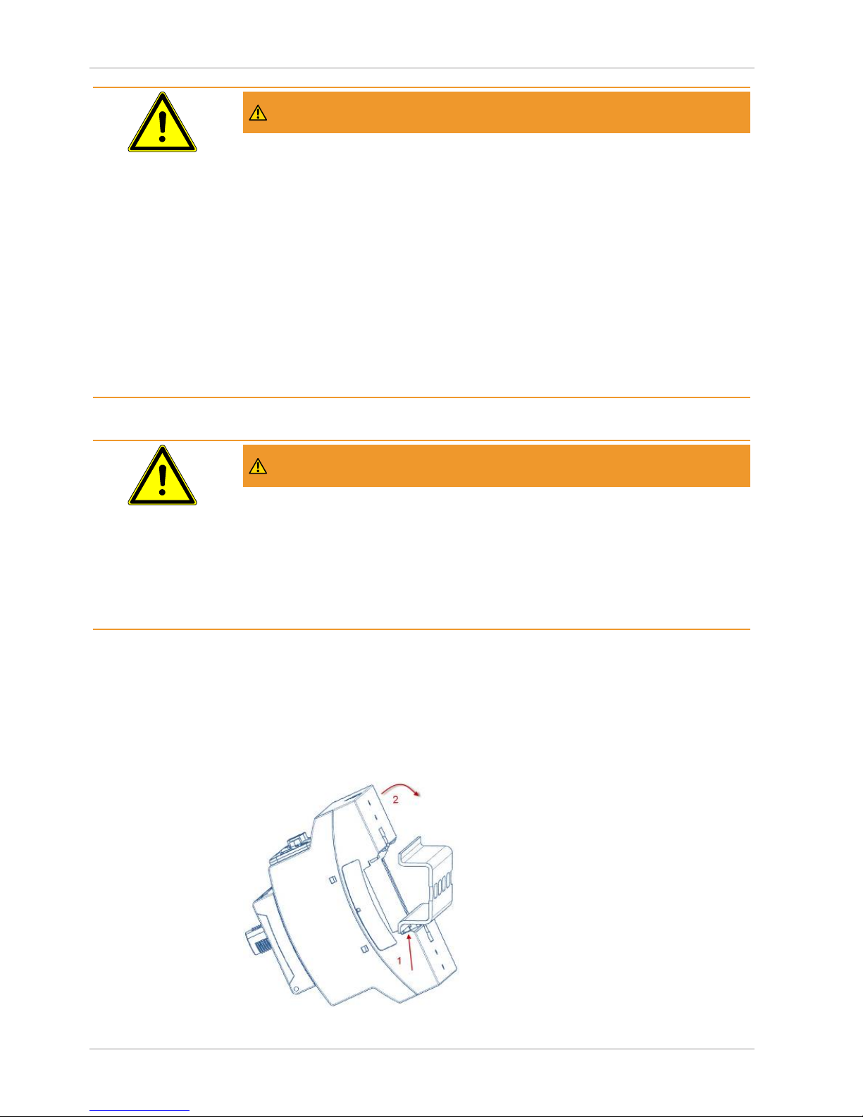
6 | Installation INFICON
64 / 84 XL3000flex-Operating-instructions-jina83en1-03-(1809)
WARNING
Danger from moisture and electricity
Moisture entering the device can lead to personal injury due to electric shocks as well
as damage to property due to short circuiting.
► Only operate the device in dry environments and only in buildings.
► Operate the device away from sources of liquid and moisture.
► Position the device so that you can always reach the power plug to unplug the
device.
► Do not operate the device standing water and do not let even a drop of water or
other liquids on the device.
► Prevent the device from coming into contact with bases, acids and solvents.
WARNING
Danger from electric shocks
Improperly earthed or protected products may be dangerous to life in case of a fault.
The use of the device is not permitted without a connected protective conductor.
► Only use the included 3-wire power cable.
► Make sure that the mains plug is always accessible.
6.2 IO module - or bus module mounting (optional)
Both modules are interfaces for controlling the leak detector XL3000flex.
Page 65

INFICON Installation | 6
XL3000flex-Operating-instructions-jina83en1-03-(1809) 65 / 84
1
Place the device with at least 20 cm distance away from all sides.
2
Connect the SL3000XL sniffer cable to the front of the XL3000flex.
3
If you want to connect the optional IO1000 I/O module or the BM1000 bus
module, mount it on the back of the device on the TS35 top hat rail.
4
To do this, first mount the profil rail (commercially available) at the intended
location on the rear of the device (see Device setup [}14]).
5
To do this, hook the module into the bottom of the top-profil rail, press it onto the
top-profil rail and let it snap into place.
6
Connect the power line to the power cord connector on the back of the
XL3000flex.
7
To turn on the XL3000flex , press the power button (see Device setup [}14]).
See also
2 Accessory list: [}10]
Page 66

7 | Warning and error messages INFICON
66 / 84 XL3000flex-Operating-instructions-jina83en1-03-(1809)
7 Warning and error messages
The instrument is equipped with extensive self-diagnostic functions.
Error messages
Errors are events that the device cannot correct itself and that force interruption of its
operation. The error message consists of a number and a descriptive text.
After you have removed the cause of the error, start operation again with the restart
key.
Warnings
Warnings warn of device states that can impair the accuracy of measurements.
Operation of the device is not interrupted.
Confirm acknowledgment of the warning with the OK key or the right key on the sniffer
handle.
The following table displays all the warnings and error messages. It lists possible
causes for the malfunction and instructions on how to eliminate these.
Please note that work marked with an asterisk must be carried out only by service
staff that is authorized by INFICON.
Warning
(Wrn)
Error (Err)
Error message
LDS3000
Error number Limit values Cause
LDS1000
Protocol
Binary or
ASCII
protocol
compatibilit
y mode
LDS1000/
LDS2010
1xx system error (RAM, ROM, EEPROM, clock, ...)
Wrn102 Timeout EEPROM MSB
Box (Parameter number)
84 43 EEPROM on IF board or MSB
defective
Wrn104 An EEPROM parameter is
initializing
84 43 Following software update or
EEPROM defective
Wrn106 EEPROM parameter
initializing
84 43 Following software update or
EEPROM defective
Wrn110 Clock not set 16 16 Jumper for clock not set, battery
drained, clock defective
Wrn122 No response from the BUS
module
99 99 Connection to BUS module
interrupted
Wrn123 Unsupported configuration
INFICON from BM1000
99 99 The selected configuration is not
supported by the connected
INFICON BM1000-fieldbus type.
Page 67
INFICON Warning and error messages | 7
XL3000flex-Operating-instructions-jina83en1-03-(1809) 67 / 84
Warning
(Wrn)
Error (Err)
Error message
LDS3000
Error number Limit values Cause
LDS1000
Protocol
Binary or
ASCII
protocol
compatibilit
y mode
LDS1000/
LDS2010
Wrn125 I/O module not connected 99 99 Connection to I/O module
interrupted
Wrn127 Wrong bootloader version 99 99 Boot loader not compatible with
application
Err129 Incorrect device
(EEPROM)
99 99 EEPROM does not contain any
compatible data
Err130 Sniffer not connected 99 99 The sniffer line is not electrical
connected.
Wrn132 SL3000 not supported Only the SL3000XL may be used
with the XL Sniffer Adapter
Wrn150 Pressure sensor 2 is not
connected
– – Connecting pressure sensor
PSG500 to a FINE connection.
2xx operating voltage error
Wrn201 U24_MSB too low 24 120 21.6V 24V power supply pack
Wrn202 U24_MSB too high 24 120 26.4V 24V power supply pack
Wrn203 24V_PWR12 voltage out of
range (TL_valve/GB_valve)
24 120 20V
30V
Short circuit at valve 1 (calibrated
leak) or valve 2 (gas ballast)
Wrn204 24V_PWR34 voltage out of
range
(valve 3/4)
24 120 20V
30V
Short circuit at valve 3 or valve 4
Wrn205 24V_PWR56 voltage out of
range (Sniff_valve/valve6)
24 120 20V
30V
Short circuit at valve 5 (sniff) or
valve 6
Wrn221 Internal voltage 24V_RC
voltage out of range
24 120 20V
30V
Short circuit 24V at the control unit
output
Wrn222 Internal voltage 24V_IO
voltage out of range
24 120 20V
30V
Short circuit 24V at IO output
Wrn223 Internal voltage 24V_TMP
voltage out of range
24 120 20V
30V
Short circuit 24V of the TMP
Wrn224 Internal voltage 24V_1
(Pirani) voltage out of
range
24 120 20V
30V
Short circuit 24V
Pressure sensor PSG500 (1,2,3),
sniffer line
Page 68
7 | Warning and error messages INFICON
68 / 84 XL3000flex-Operating-instructions-jina83en1-03-(1809)
Warning
(Wrn)
Error (Err)
Error message
LDS3000
Error number Limit values Cause
LDS1000
Protocol
Binary or
ASCII
protocol
compatibilit
y mode
LDS1000/
LDS2010
Wrn240 Voltage +15V out of range 24 120 +15V too low, IF board or MSB
defective
Wrn241 Voltage -15V out of range 24 120 -15V too low, short circuit at
preamplifier, IF board or MSB
defective
Err242 +15V or -15V voltage
shorted
24 120 +15V or -15V too low, short circuit
at preamplifier, IF board or MSB
defective
Wrn250 REF5V voltage out of
range
24 120 4.5V
5.5V
+15V or 5V too low, short circuit at
preamplifier, IF board or MSB
defective
Err252 REF5V voltage shorted 24 120 +15V or REF5V too low, short
circuit at preamplifier, IF board or
MSB defective
3xx detection system (offset preamplifier, preamplifier test, emission, cathode test)
Wrn300 Anode voltage too low 41 132 7V < the
setpoint
Short circuit anode voltage,
pressure in mass spectrometer
too high, IF board, MSB or ion
source defective
Wrn301 Anode voltage too high 40 131 7V > the
setpoint
MSB defective
Wrn302 Suppressor voltage too low 39 130 297V Short circuit suppressor, IF board
or MSB defective
Wrn303 Suppressor voltage too
high
38 129 363V MSB defective
Wrn304 Anode-cathode voltage too
low
36 127 40V Short circuit anode-cathode, IF
board or MSB defective
Wrn305 Anode-cathode voltage too
high
35 126 140V MSB defective
Page 69
INFICON Warning and error messages | 7
XL3000flex-Operating-instructions-jina83en1-03-(1809) 69 / 84
Warning
(Wrn)
Error (Err)
Error message
LDS3000
Error number Limit values Cause
LDS1000
Protocol
Binary or
ASCII
protocol
compatibilit
y mode
LDS1000/
LDS2010
Err306 Anode voltage faulty 36 127 40 V
deviation
from the
default
value
The anode voltage does not
match the default value or the set
value is outside the allowable
setting range.
Wrn310 Cathode 1 is defective 45 136 Cathode defective, line to cathode
interrupted, IF board or MSB
defective
Wrn311 Cathode 2 is defective 46 137 Cathode defective, line to cathode
interrupted, IF board or MSB
defective
Err312 Cathode defective 47 138 Cathode defective, line to cathode
interrupted, IF board or MSB
defective
Err340 Emission error 44 135 < 90% of
the target
value
> 110% of
the target
value
Emission was stable previously,
pressure probably too high,
message after 15s
Wrn342 Cathode not connected 47 138 Both cathodes defective during
self-testing after switch on or plug
not connected
Wrn350 Suppressor not connected 39 130 Supressor cable is not plugged in
or defective during the self-test
after switching on
Wrn352 Preamplifier not connected Preamplifier defective, cable not
plugged in
Err358 Preamplifier oscillates
between 2 ranges
Signal varies too much (see
command 1120)
Preamplifier defective
Wrn359 Overdriven preamplifier 31 123 Signal too large preamplifier
defective
Page 70
7 | Warning and error messages INFICON
70 / 84 XL3000flex-Operating-instructions-jina83en1-03-(1809)
Warning
(Wrn)
Error (Err)
Error message
LDS3000
Error number Limit values Cause
LDS1000
Protocol
Binary or
ASCII
protocol
compatibilit
y mode
LDS1000/
LDS2010
Wrn360 Preamplifier output too low 31 123 <-70 mV at
500 GΩ
Poor ion source or contaminated
mass spectrometer
Wrn361 Preamplifier offset too high 31 123 >+/-50mV
at 500GΩ,
>+/-10mV
at 15GΩ,
<+/-10mV
at 470MΩ,
<+/-9mV
at 13 MΩ
Preamplifier defective
Wrn362 Preamplifier range error 31 123 Preamplifier or MSB box defective
Wrn390 500 G outside the range 31 123 450GΩ
550GΩ
Preamplifier defective, error at the
suppressor, IF board or MSB
defective
4xx TMP fault (also temperature)
Err400 TMP fault number 49 15
Wrn401 TMP warning number
Err402 No communication with
TMP
49 15 Cable to TMP / TMP defective, IF
board or MSB defective
Err403 TMP rotation speed too
low
53 142 < 95% of
the target
value
Pressure too high, TMP defective
Err404 TMP current consumption
too high
49 2 3A
Err405 No TMP run-up time 60 61 5 min. Pressure too high, TMP faulty
Err410 TMP temperature too high 49 2 61°C Cooling failed, check MSB module
operating conditions
Wrn411 High TMP temperature 49 2 60°C Cooling failed, check MSB module
operating conditions
Err420 TMP voltage too high 49 2 Power supply defective, TMP
defective
Page 71

INFICON Warning and error messages | 7
XL3000flex-Operating-instructions-jina83en1-03-(1809) 71 / 84
Warning
(Wrn)
Error (Err)
Error message
LDS3000
Error number Limit values Cause
LDS1000
Protocol
Binary or
ASCII
protocol
compatibilit
y mode
LDS1000/
LDS2010
Wrn421 TMP voltage too low Cable cross-section 24 V supply
for MSB modules too low, output
current 24-V power supply too low
(I <10 A), power supply defective,
TMP defective
Err422 TMP no run-up time 49 2 8 min. TMP foreline pressure too high,
VV pump final pressure too high,
leakage high vacuum system,
flood valve not close, TMP bearing
damage, TMP flawed
Err423 TMP pressure rise 49 2 Inrush of air, flood valve defective
or incorrectly dimensioned
5xx Pressure and flow errors
Wrn500 Pressure sensor not
connected
58 144 0.5V Pressure sensor PSG500 P1 not
connected, IF board or MSB
defective
Wrn502 Pressure sensor 2 not
connected
Pressure sensor PSG500 P2 not
connected, IF board or MSB
defective.
Wrn520 Pressure too high 73 148 18 mbar Pressure p1 too high
Wrn521 Pressure rise, anode
voltage collapse
73 148 < Setpoint
- 20V
Pressure p1 too high, message
after 1.4s
Wrn522 Pressure rise, emission
collapsed
73 148 < 90% of
the target
value
> 110% of
the target
value
Emission was stable previously,
pressure p1 too high, message
after 5s
Wrn540 Pressure too low, Sniffer
blocked
63 62 Sniffer flow
warning
parameter
Sniffer clogged, sniffer valve
defective,filter clogged
Page 72
7 | Warning and error messages INFICON
72 / 84 XL3000flex-Operating-instructions-jina83en1-03-(1809)
Err541 Sniffer blocked (p1) 62 146 Sniffer blocked, sniffer valve
defective (pressure lower than half
of the configured warning value),
filter clogged
Wrn542 Sniffer broken 64 147 Sniffer broken
Wrn550 Pressure too low, XL
Sniffer blocked
Clean or replace the high flow
capillary of the sniffer line.
Replace soiled filter.
Wrn552 XL Sniffer broken Replace the high flow capillary of
the sniffer line.
Wrn554 XL Sniffer P2 too small 63 62 Pressure on SL3000XL too low in
low flow.
6xx Calibration errors
Wrn600 Calibration factor too low 81 153 0.01 Calibration leak or machine factor
set incorrectly
Wrn601 Calibration factor too high 81 153 10000 Calibrated leak or machine factor
set incorrectly, partial flow factor
too high
Wrn602 KalFaktor lower than last
calibration
81 153 < 50% of
the old
value
Calibrated leak, machine factor or
partial flow factor has changed
Wrn603 KalFaktor higher than last
calibration
81 153 > 200% of
the old
value
Calibrated leak, machine factor or
partial flow factor has changed
Wrn604 Int. Cal. not possible, lack
of calibration leak control
81 153 calibration leak is not enabled
Wrn605 Difference during
calibration too small
Calibration leak defective or signal
too weak.
Wrn610 Machine factor too low 81 153 1.00E-04 Machine factor adjustment
inaccurate
Wrn611 Machine factor too high 81 153 1.00E+04 Machine factor adjustment
inaccurate, partial flow factor too
high
Wrn612 Machine factor lower than
last time
81 153 < 50% of
the old
value
Partial flow factor has changed
Wrn613 Machine factor greater
than last time
81 153 > 200% of
the old
value
Partial flow factor has changed
Page 73
INFICON Warning and error messages | 7
XL3000flex-Operating-instructions-jina83en1-03-(1809) 73 / 84
Wrn625 Int. calibration leak not set 0 0 Leak rate of int. calibration leak is
still set to factory setting
Wrn626 Ext. Calibration leak not
set
0 0 Leak rate of calibration leak is still
set to factory setting
Wrn630 Calibration request 0 0 Temperature change of 5°C,
Rotation speed was changed
since last calibration, 30-minute
switch-on time and still no
calibration conducted
Wrn650 Calibration is not
recommended in the first
20 minutes
A calibration during the first 20
minutes after starting (warm-up
phase) the leak detector is not
recommended.
The warning message can be
turned off:
- LD protocol: Bef 429
– ASCII *CONFig:CALWarn
(ON,OFF)
Wrn670 Calibration error 81 153 Since a problem has occurred
during the calibration, you have to
recalibrate.
Wrn671 Peak not found 81 153 The signal was too restless during
the peak search. Calibration has
been aborted.
Wrn680 Deviation to the calibration
detected
0 0 The verification of calibration has
shown that you should recalibrate.
7xx temperature errors (preamplifier, electronics)
Wrn700 Preamplifier temp. too low 33 60 2°C Temperature too low
Wrn702 Preamplifier temp. too high 32 124 60°C Temperature too high
Wrn710 MSB temperature too high 54 44 58°C Temperature too high
Err711 Max. MSB temperature
exceeded
54 44 65°C Temperature too high
8xx not used
9xx maintenance messages (e.g. TMP)
Wrn901 Maintenance bearing/
lubricant
99 99 3 years TMP maintenance necessary
Wrn910 Maintenance diaphragm
pump
99 99 8000 hour maintenance of
diaphragm pump required
Page 74

8 | Cleaning and maintenance INFICON
74 / 84 XL3000flex-Operating-instructions-jina83en1-03-(1809)
8 Cleaning and maintenance
All cleaning and maintenance work described here must be carried out without
opening the device!
WARNING
Life threatening hazard from electric shock
High voltages are inside the device. Touching parts where electrical voltage is present
can result in death.
► Disconnect the device from the power supply prior to any installation and
maintenance work.. Ensure that the electrical supply cannot be switched back on
unintentionally.
8.1 Cleaning the housing
Wipe the housing with a soft damp cloth.
Use only water to moisten. Avoid cleaners that contain alcohol, fat or oil.
8.2 Maintenance of the XL3000flex
As a rule, maintenance work is carried out by INFICON Service. It is not intended that
you open the housing of the XL3000flex.
You can change the fuses, the filter mats of the fan inlet and the filter in the sniffer tip
without opening the device.
8.2.1 Change the filter mat of the fan input
Depending on the location, the filter mat on the back of the device may become dirty.
Check the filter mat periodically and change it, if the filter mat is significant dirty.
ü You have a new filter set.
1
Make sure that the device is disconnected from the power supply by pulling the
power plug securely.
2
Gently lift the lower corners of the plastic grid and remove the plastic grid with
the filter mat.
3
Replace the dirty filter set.
Page 75

INFICON Cleaning and maintenance | 8
XL3000flex-Operating-instructions-jina83en1-03-(1809) 75 / 84
8.2.2 Replacing the fuses
DANGER
Life threatening hazard from electric shock
► Disconnect the device from the power supply.
► Ensure that the electrical supply cannot be switched back on unintentionally.
1
Switch off the device and disconnect from the mains.
2
Pull the plug of the power cable out of the device.
3
The fuse holder of the device is located under a cover next to the power switch.
Carefully remove the cover with the fuses attached underneath out of the
device.
4
Remove the fuses and check them for any damage.
5
If necessary, replace the fuses. Only use replacement fuses of the same type
and performance as supplied.
6
Two fuses of the same type must be used.
7
Press the fuse holder along with the fuses back into the starting position until
the cover locks into place.
8.2.3 Replacing the filter cartridge on the sniffer probe
The replacement interval depends on the ambient conditions. The filter cartridge must
generally be replaced every 500 to 1500 operating hours.
The filter cartridge is in the sniffer probe.
Page 76

8 | Cleaning and maintenance INFICON
76 / 84 XL3000flex-Operating-instructions-jina83en1-03-(1809)
1
2
3
Position Description
1 Sniffer tip
2 Cap nut
3 Filter cartridge
1
Remove the sniffer probe: Release the cap nut of the sniffer probe manually or
with a screw driver (SW21).
2
Remove the old filter cartridge and insert a new filter cartridge.
3
Put the sniffer probe on the handle and tighten the cap nut manually only.
4
Check for tightness:
If no air can be drawn in, the unit signals the warning W41. If the end of the sniffer tip
is closed and the warning is not reported, the screw connection at the sniffer tip is
leaking or the filter cartridge is not seated correctly.
1
Unscrew the plastic cap on the end of the filter tip.
2
Close the end of the sniffer probe with the thumb. If there is no warning, tighten
the cap nut and – if that is not successful – check the seat of the filter.
3
Tighten the plastic cap on the end the sniffer probe again.
4
Calibrating the device
Page 77

INFICON Cleaning and maintenance | 8
XL3000flex-Operating-instructions-jina83en1-03-(1809) 77 / 84
8.3 Sending for repair or maintenance
Maintenance inside the device may only be performed by the manufacturer. We
recommend having the device serviced periodically by the manufacturer's service.
You can send in your device to INFICON so it can be maintained or repaired. For
further details see "Sending in the instrument”.
See also
2 Sending in the device [}78]
Page 78

9 | Decommissioning the measuring instrument INFICON
78 / 84 XL3000flex-Operating-instructions-jina83en1-03-(1809)
9 Decommissioning the measuring
instrument
9.1 Sending in the device
WARNING
Danger due to harmful substances
Contaminated devices could endanger the health. The contamination declaration
serves to protect all persons who come into contact with the device.
► Fill in the declaration of contamination completely.
1
Please do not hesitate to contact the manufacturer and send a completed
declaration of contamination before sending anything to us.
ð You will then receive a return number.
2
Use the original packaging when returning.
3
Before sending the device, attach a copy of the completed contamination
declaration. See below.
Page 79

INFICON Decommissioning the measuring instrument | 9
XL3000flex-Operating-instructions-jina83en1-03-(1809) 79 / 84
Page 80
10 | CE Declaration of Conformity INFICON
80 / 84 XL3000flex-Operating-instructions-jina83en1-03-(1809)
10 CE Declaration of Conformity
Page 81

INFICON Index
XL3000flex-Operating-instructions-jina83en1-03-(1809) 81 / 84
Index
A
Access controls 30
Ambient temperature 19
B
Brightness 35
C
Calibrating
External Calibration Configuration and Start 47
Time and general preferences 46
Cathode 32
Cleaning and maintenance 74
Cleaning works 74
Copy files 56
D
Date 29
Declaration of Contamination 78, 79
Description 12
Detection limit 12
Dimensions 18
E
Error message 66
F
Factory settings 19
fan input 16
G
Gas flow 13
H
Handle 23
High flow 12
I
I/O port 36
Ingress protection 18
K
Keyboard lock 24
L
Language 28
Leak rate unit 29
Low flow 12
M
Main fuse 18
Mains switch 28
Maintenance 74
Measurement display 24
Measurement view 34
Measuring 53
N
Noise behavior 53
O
Operating voltage 18
Operation mode 13
P
Pollution degree 19
Power 18
Pressure unit 30
R
Reset 62
Return 78
Page 82

Index INFICON
82 / 84 XL3000flex-Operating-instructions-jina83en1-03-(1809)
S
Scope of delivery 10
Setting setpoints 45
Sniffer line 12
Sniffer mode 44
Speaker 14
Storage temperature 19
T
Time 29
Touchscreen 14, 33
U
USB flash drive 56
V
View 14
Volume 32
W
Warning 35, 66
Weight 18
Page 83

Page 84

 Loading...