

Indesit K6G21S, K6G21SP, KN6G21S, KN6G21SP, K6G21P Operating Instructions Manual
...
K6G21S/P
KN6G21S/P
GB
English
Operating Instructions
COOKER AND OVEN
Contents
Operating Instructions,1
Description of the appliance-Overall view,2
Description of the appliance-Control Panel,3
Installation,4
Start-up and use,9
Precautions and tips,12
Care and maintenance,13
Assistance,13
ES
Español
Manual de instrucciones
COCINA Y HORNO
Sumario
Manual de instrucciones,1
Descripción del aparato-Vista de conjunto,2
Descripción del aparato-Panel de control,3
Instalación,14
Puesta en funcionamiento y uso,19
Precauciones y consejos,22
Mantenimiento y cuidados,23
Asistencia,23
PT
Português
Instruções para a utilização
FOGÃO E FORNO
Índice
Instruções para a utilização,1
Descrição do aparelho-Vista de conjunto,2
Descrição do aparelho-Painel de comandos,3
Instalação,24
Início e utilização, 28
Precauções e conselhos,31
Manutenção e cuidados,32
Assistência técnica,32

GB
Description of the appliance
Overall view
1 Hob burner
2 Hob Grid
3.Control panel
4.Sliding grill rack
5.DRIPPING pan
6.Adjustable foot
7.Containment surface for spills
8.GUIDE RAILS for the sliding racks
9.position 5
10.position 4
11.position 3
12.position 2
13.position 1
14 Glass Cover *(Available only on certain models)
Descrição do aparelho
PT
Vista de conjunto
1. Queimador a gás
2. Grade do piano de trabalho
3. Painel de comandos
4. Prateleira GRADE
5. Prateleira BANDEJA PINGADEIRA
6. Pé de regulação
7. Plano de retenção dos eventuais vazamentos
8. GUIAS de deslizamento das prateleiras
9. Posição 5
10. Posição 4
11.Posição 3
12. Posição 2
13. Posição 1
14. O sobretampo de vidro
(Presente apenas em alguns modelos)
ES
1. Quemador de gas
2.Plano de contención eventuales derrames
3. Panel de mandos
4. Rejilla estante del horno
5. Asadera o plano de cocción
6. Patitas regulables
7. Rejilla del plano de cocción
8. GUÍAS de deslizamiento de las bandejas
9.
10.
11.
12.
13.
14.Tapa de vidrio (Presente sólo en algunos modelos)
2
Descripción del aparato
Vista de conjunto
POSICIÓN 5
POSICIÓN 4
POSICIÓN 3
POSICIÓN 2
POSICIÓN 1
GB
1
5
6
4
4
5
GB
2
3
1
2
3
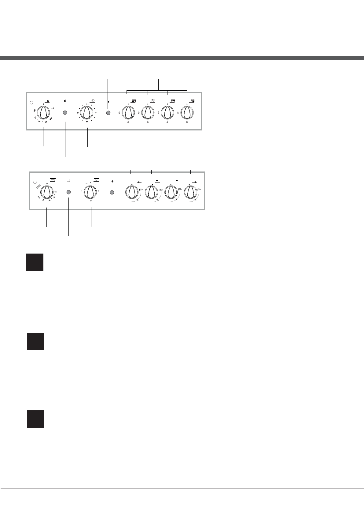
Description of the appliance
Control panel
1.THERMOSTAT indicator light.
2.OVEN CONTROL knob
3.OVEN LIGHT button
4.TIMER knob*
5.GAS BURNER IGNITION button*
6.Hob BURNER control knob
* Only available in certain models.
6
ES
Descripción del aparato
Panel de control
1.La luz piloto del termóstato del horno
2.Perilla del horno
3.Botón de la luz del forno y asador automático
4.El contador de minutos*
5.Encendido electrónico de los quemadores*
6.Perillas de mando de los quemadores
* Presente sólo en algunos modelos.
Descrição do aparelho
PT
Painel de comandos
1.Indicador de funcionamento termostato
2.Manípulo do forno
3.Manípulo luz do forno
4.Manípulo conta-minutos*
5.Acendedor electrónico dos queimadores do plano*
6.Botão luz do forno e rotisserie
* Presente apenas em alguns modelos.
3
Installation
GB
! Before operating your new appliance please read
this instruction booklet carefully. It contains important
information concerning the safe installation and
operation of the appliance.
! Please keep these operating instructions for future
reference. Make sure that the instructions are kept with
the appliance if it is sold, given away or moved.
! The appliance must be installed by a qualified
professional according to the instructions provided.
! Any necessary adjustment or maintenance must be
performed after the cooker has been disconnected
from the electricity supply.
Room ventilation
The appliance may only be installed in permanentlyventilated rooms, according to current national
legislation. The room in which the appliance is installed
must be ventilated adequately so as to provide as
much air as is needed by the normal gas combustion
3
process (the flow of air must not be lower than 2 m
/h
per kW of installed power).
The air inlets, protected by grilles, should have a duct
2
with an inner cross section of at least 100 cm
and
should be positioned so that they are not liable to even
partial obstruction (see gure A).
These inlets should be enlarged by 100% - with a
2
minimum of 200 cm
- whenever the surface of the
hob is not equipped with a flame failure safety device.
When the flow of air is provided in an indirect manner
from adjacent rooms (see gure B), provided that these
are not communal parts of a building, areas with
increased fire hazards or bedrooms, the inlets should
be fitted with a ventilation duct leading outside as
described above.
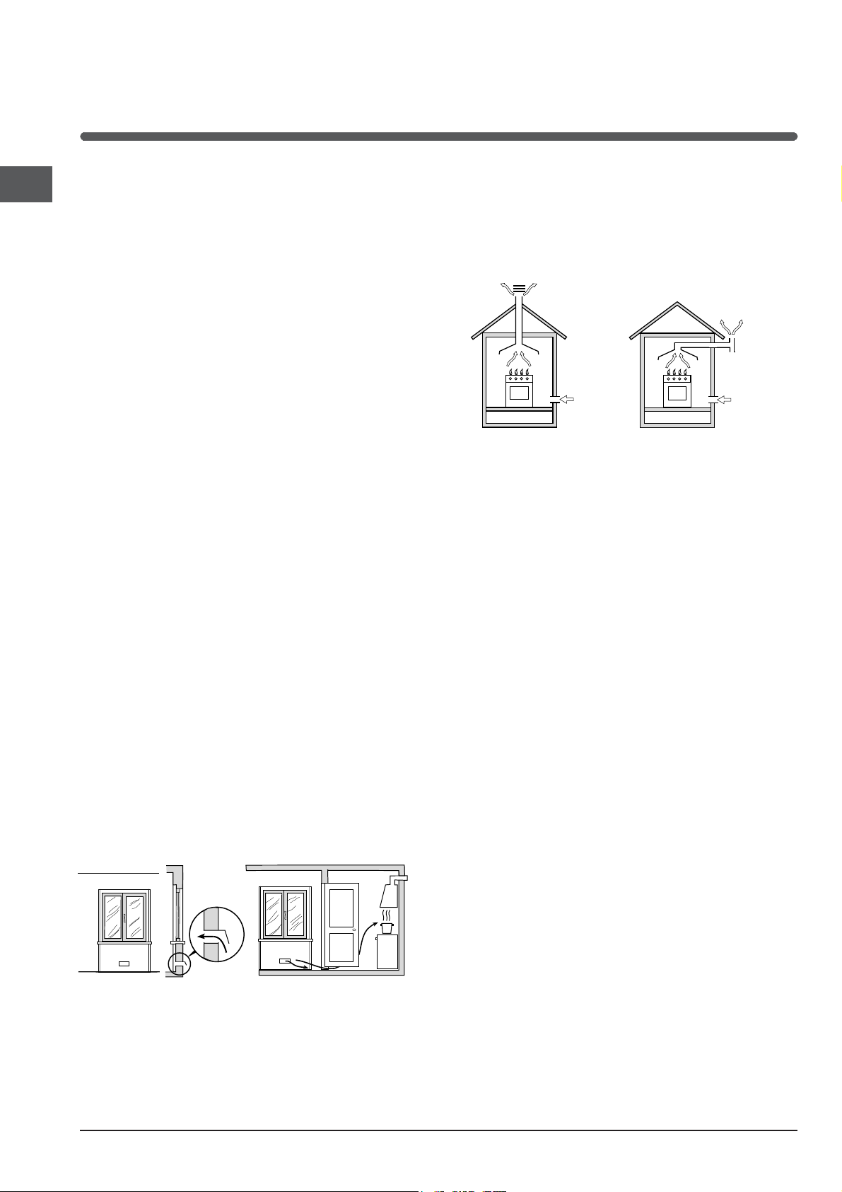
Disposing of combustion fumes
The disposal of combustion fumes should be
guaranteed using a hood connected to a safe and
efficient natural suction chimney, or using an electric
fan that begins to operate automatically every time the
appliance is switched on (see gure).
Fumes channelled
straight outside
Fumes channelled through
a chimney or a branched
flue system (reserved for
cooking appliances)
! The liquefied petroleum gases are heavier than air
and collect by the floor, therefore all rooms containing
LPG cylinders must have openings leading outside so
that any leaked gas can escape easily.
LPG cylinders, therefore, whether partially or
completely full, must not be installed or stored in rooms
or storage areas that are below ground level (cellars,
etc.). Only the cylinder being used should be stored
in the room; this should also be kept well away from
sources of heat (ovens, chimneys, stoves) that may
cause the temperature of the cylinder to rise above
50°C.
Positioning and levelling
! It is possible to install the appliance alongside
cupboards whose height does not exceed that of the
hob surface.
Adjacent room Room
requiring
ventilation
A
Ventilation opening
for comburent air
Increase in the gap
between the door and
the flooring
A B
! After prolonged use of the appliance, it is advisable to
open a window or increase the speed of any fans used.
4
! Make sure that the wall in contact with the back of
the appliance is made from a non-flammable, heatresistant material (T 90°C).
To install the appliance correctly:
• Place it in the kitchen, dining room or the bed-sit (not
in the bathroom).
• If the top of the hob is higher than the cupboards,
the appliance must be installed at least 600 mm away
from them.
• If the cooker is installed underneath a wall cabinet,
there must be a minimum distance of 420 mm
between this cabinet and the top of the hob. This
distance should be increased to 700 mm if the wall
cabinets are flammable (see gure).

• Do not position
HOOD
420
Min.
min.
650
mm. with hood
min.
700
mm. without hood
mm.
600
Min. mm.
420
Min. mm.
blinds behind the cooker or less than 600 mm away
from its sides.
• Any hoods must be installed according to the
instructions listed in the relevant operating manual.
• The voltage is in the range between the values
indicated on the data plate.
• The socket is compatible with the plug of the
appliance. If the socket is incompatible with the
plug, ask an authorised technician to replace it. Do
not use extension cords or multiple sockets.
! Once the appliance has been installed, the power
supply cable and the electrical socket must be easily
accessible.
! The cable must not be bent or compressed.
! The cable must be checked regularly and replaced
by authorised technicians only.
GB
Levelling
If it is necessary to level the
appliance, screw the adjustable
feet into the places provided on
each corner of the base of the
cooker (see gure).
The legs* fit into the slots on the
underside of the base of the
cooker.
Electrical connection
Install a standardised plug corresponding to the load
indicated on the appliance data plate (see Technical
data table).
The appliance must be directly connected to the mains
using an omnipolar circuit-breaker with a minimum contact
opening of 3 mm installed between the appliance and the
mains. The circuit-breaker must be suitable for the charge
indicated and must comply with NFC 15-100 regulations
(the earthing wire must not be interrupted by the circuitbreaker). The supply cable must be positioned so that it
does not come into contact with temperatures higher than
50°C at any point.
Before connecting the appliance to the power supply,
make sure that:
• The appliance is earthed and the plug is compliant with
the law.
• The socket can withstand the maximum power of the
appliance, which is indicated by the data plate.
* Only available in certain models
! The manufacturer declines any liability should
these safety measures not be observed.
Gas connection
Connection to the gas network or to the gas cylinder
may be carried out using a flexible rubber or steel hose,
in accordance with current national legislation and after
making sure that the appliance is suited to the type of gas
with which it will be supplied (see the rating sticker on
the cover: if this is not the case see below). When using
liquid gas from a cylinder, install a pressure regulator
which complies with current national regulations. To
make connection easier, the gas supply may be turned
sideways*: reverse the position of the hose holder with
that of the cap and replace the gasket that is supplied
with the appliance.
! Check that the pressure of the gas supply is
consistent with the values indicated in the Table
of burner and nozzle specifications (see below).
This will ensure the safe operation and durability of
your appliance while maintaining efficient energy
consumption.
Gas connection using a flexible rubber hose
Make sure that the hose complies with current national
legislation. The internal diameter of the hose must
measure: 8 mm for liquid gas supply; 13 mm for
methane gas supply.
Once the connection has been performed, make sure
that the hose:
• Does not come into contact with any parts that reach
temperatures of over 50°C.
• Is not subject to any pulling or twisting forces and
that it is not kinked or bent.
• Does not come into contact with blades, sharp
corners or moving parts and that it is not
compressed.
5

GB
V
• Is easy to inspect along its whole length so that its
condition may be checked.
• Is shorter than 1500 mm.
• Fits firmly into place at both ends, where it will
be fixed using clamps that comply with current
regulations.
! If one or more of these conditions is not fulfilled
or if the cooker must be installed according to the
conditions listed for class 2 - subclass 1 appliances
(installed between two cupboards), the flexible steel
hose must be used instead (see below).
Connecting a flexible jointless stainless steel pipe
to a threaded attachment
Make sure that the hose and gaskets comply with
current national legislation.
To begin using the hose, remove the hose holder on
the appliance (the gas supply inlet on the appliance is
a cylindrical threaded 1/2 gas male attachment).
! Perform the connection in such a way that the hose
length does not exceed a maximum of 2 metres,
making sure that the hose is not compressed and does
not come into contact with moving parts.
Adjusting the hob burners’ minimum setting:
1. Turn the tap to the minimum position.
2. Remove the knob and adjust the regulatory screw,
which is positioned inside or next to the tap pin, until
the flame is small but steady.
! If the appliance is connected to a liquid gas supply,
the regulatory screw must be fastened as tightly as
possible.
3. While the burner is alight, quickly change the position of
the knob from minimum to maximum and vice versa several
times, checking that the flame is not extinguished.
! The hob burners do not require primary air
adjustment.
Adapting the oven
Replacing the oven burner nozzle:
1. Open the oven door fully
2. Pull out the sliding oven
bottom (see diagram).
Checking the tightness of the connection
When the installation process is complete, check the
hose fittings for leaks using a soapy solution. Never
use a flame.
Adapting to different types of gas
It is possible to adapt the appliance to a type of gas
other than the default type (this is indicated on the
rating label on the cover).
Adapting the hob
Replacing the nozzles for the hob burners:
1. Remove the hob grids and slide the burners off their
seats.
2. Unscrew the nozzles using
a 7 mm socket spanner (see
gure), and replace them with
nozzles suited to the new type
of gas (see Burner and nozzle
speci cations table).
3. Replace all the components
by following the above
instructions in reverse.
3. Remove the oven burner
after unscrewing the screws V
(see gure).
4. Unscrew the nozzle using a
special nozzle socket spanner
(see gure) or with a 7 mm
socket spanner, and replace it
with a new nozzle that is suited
to the new type of gas (see
Burner and nozzle speci cations
table).
Adjusting the gas oven burner’s minimum setting
1. Light the burner (see Start-up and Use).
2. Turn the knob to the minimum position (MIN)
after it has been in the maximum position (MAX) for
approximately 10 minutes.
3. Remove the knob.
4. Tighten or loosen the adjustment screws on the
outside of the thermostat pin (see gure) until the flame
is small but steady.
! If the appliance is connected to liquid gas, the
6

regulation screw must be fastened as tightly as
possible.
TECHNICAL DATA
Oven Dimensions
HxWxD
Volume
Useful
measurements
relating to the
oven compartment
GB
31x43,5x43,5 cm
58 l
width 46 cm
depth 42 cm
height 8,5 cm
5. Turn
the knob from the MAX position to the MIN position
quickly or open and shut the oven door, making sure
that the burner is not extinguished.
! Be careful of the spark plug wires and the
thermocouple tubes.
! After adjusting the appliance so it may be used with
a different type of gas, replace the old rating label with
a new one that corresponds to the new type of gas
(these labels are available from Authorised Technical
Assistance Centres).
! Should the gas pressure used be different (or vary
slightly) from the recommended pressure, a suitable
pressure regulator must be fitted to the inlet hose in
accordance with current national regulations relating to
“regulators for channelled gas”.
Voltage and
frequency
Burners
see data plate
may be adapted for use with any
type of gas shown on the data
plate.
EC Directives 2006/95/EC dated
12/12/06 (Low Voltage) and
subsequent amendments 04/108/EC dated 15/12/04
(Electromagnetic Compatibility)
and subsequent amendments -
2009/142/EC dated 30/11/09 (Gas)
and subsequent amendments 90/68/EEC dated 22/07/93 and
subsequent amendments. 2002/96/EC.
1275/2008(Stand-by/Off-mode)
7

GB
S
S
R
A
Table of burner and nozzle specifications
Table 1 Liquid Gas Natural Gas
Burner Diameter
(mm)
Thermal Power
kW (p.c.s .* )
By-Pass
1/100
Nozzle
1/100
Flow*
g/h
Nozzle
1/100
Flow*
Nominal Reduced (mm) (mm) *** ** (mm)
Fast
(Large)(R)
Semi Fast
(Medium)(S)
Auxiliary
(Small)(A)
100 3,00 0,7 41 86 218 214 116 286
75 1,90 0,4 30 70 138 136 106 181
55 1,00 0,4 30 50 73 71 79 95
Oven - 2,60 1,0 52 78 189 186 119 248
Supply
Pressures
* At 15°C and 1013 mbar - dry gas
** Propane P.C.S. = 50.37 MJ/Kg
*** Butane P.C.S. = 49.47 MJ/Kg
Natural P.C.S. = 37.78 MJ/m
Nominal (mbar)
Min imum (mb a r)
Maximum (mb a r)
3
28-30
20
35
37
25
45
20
17
25
l/h
K6G21S/P
KN6G21S/P
8

Start-up and use
F
Using the hob
Lighting the burners
For each BURNER knob there is a complete ring
showing the strength of the flame for the relevant
burner.
To light one of the burners on the hob:
1. Bring a flame or gas lighter close to the burner.
2. Press the BURNER knob and turn it in an
anticlockwise direction so that it is pointing to the
maximum flame setting E.
3. Adjust the intensity of the flame to the desired level
by turning the BURNER knob in an anticlockwise
direction. This may be the minimum setting C, the
maximum setting E or any position in between the two.
If the appliance is fitted with an electronic lighting
device* (see gure), press the
ignition button, marked with
, then hold the
the symbol
BURNER knob down and turn
it in an anticlockwise direction,
towards the maximum flame
setting, until the burner is lit.The
burner may be extinguished
when the knob is released. If this occurs, repeat the
operation, holding the knob down for a longer period of
time.
! If the flame is accidentally extinguished, switch off the
burner and wait for at least 1 minute before attempting
to relight it.
If the appliance is equipped with a flame failure
safety device*, press and hold the BURNER knob for
approximately 2-3 seconds to keep the flame alight
and to activate the device.
To switch the burner off, turn the knob until it reaches
the stop position
Practical advice on using the burners
For the burners to work in the most efficient way
possible and to save on the amount of gas consumed, it
is recommended that only pans that have a lid and a flat
base are used. They should also be suited to the size of
the burner.
•.
1
Burner ř Cookware diameter (cm)
Rapid (R) 24 - 26
Semi-R a p id (S) 16 - 2 0
Auxilliary (A) 10 - 14
To
identify the type of burner, please refer to the diagrams
contained in the “Burner and nozzle specifications”.
! On the models supplied with a reducer shelf, remember
that this should be used only for the auxiliary burner when
you use casserole dishes with a diameter under 12 cm.
Using the oven
! The first time you use your appliance, heat the empty
oven with its door closed at its maximum temperature for
at least half an hour. Ensure that the room is well ventilated
before switching the oven off and opening the oven door.
The appliance may emit a slightly unpleasant odour caused
by protective substances used during the manufacturing
process burning away.
! Never put objects directly on the bottom of the oven; this
will avoid the enamel coating being damaged.
Lighting the oven
To light the oven burner, bring a flame or gas lighter close to
opening F (see gure) and press the OVEN control knob while
turning it in an anticlockwise direction until it reaches the
MAX position.
If the appliance is fitted with an electronic lighting device*
(see figure), simply press the
OVEN control knob and turn it in an
anticlockwise direction, towards the
MAX position, until the burner is lit.
If, after 15 seconds, the burner is still
not alight, release the knob, open
the oven door and wait for at least 1
minute before trying to light it again. If
there is no electricity the burner may be lit using a flame or a
lighter, as described above.
! The oven is fitted with a safety device and it is therefore
necessary to hold the OVEN control knob down for
approximately 6 seconds.
GB
WARNING! The glass lid can break in if
it is heated up. Turn off all the burners
and the electric plates before closing
the lid. *Applies to the models with glass
cover only.
! If the flame is accidentally extinguished, switch off the
burner and wait for at least 1 minute before attempting to
relight the oven.
Only available in certain models.
*
9
GB
Adjusting the temperature
To set the desired cooking temperature, turn the
OVEN control knob in an anticlockwise direction.
Temperatures are displayed on the control panel and
may vary between MIN (150°C) and MAX (250°C).
Once the set temperature has been reached, the oven
will keep it constant by using its thermostat.
Grill
By turning the OVEN control knob in an anticlockwise
direction until it reaches the
ray grill is activated. The grill enables the surface of
food to be browned evenly and is particularly suitable
for roast dishes, schnitzel and sausages. Place the
rack in position 4 or 5 and the dripping pan in position
1 to collect fat and prevent the formation of smoke.
! The GRILL indicator light shows when the grill is
operating.
! Always use the grill with the oven door shut; this
achieves better cooking results and saves energy
(approximately 10%).
position, the infrared
almost one complete revolution to set the buzzer.
2. Turn the TIMER knob in an anticlockwise direction 5
to set the desired length of time.
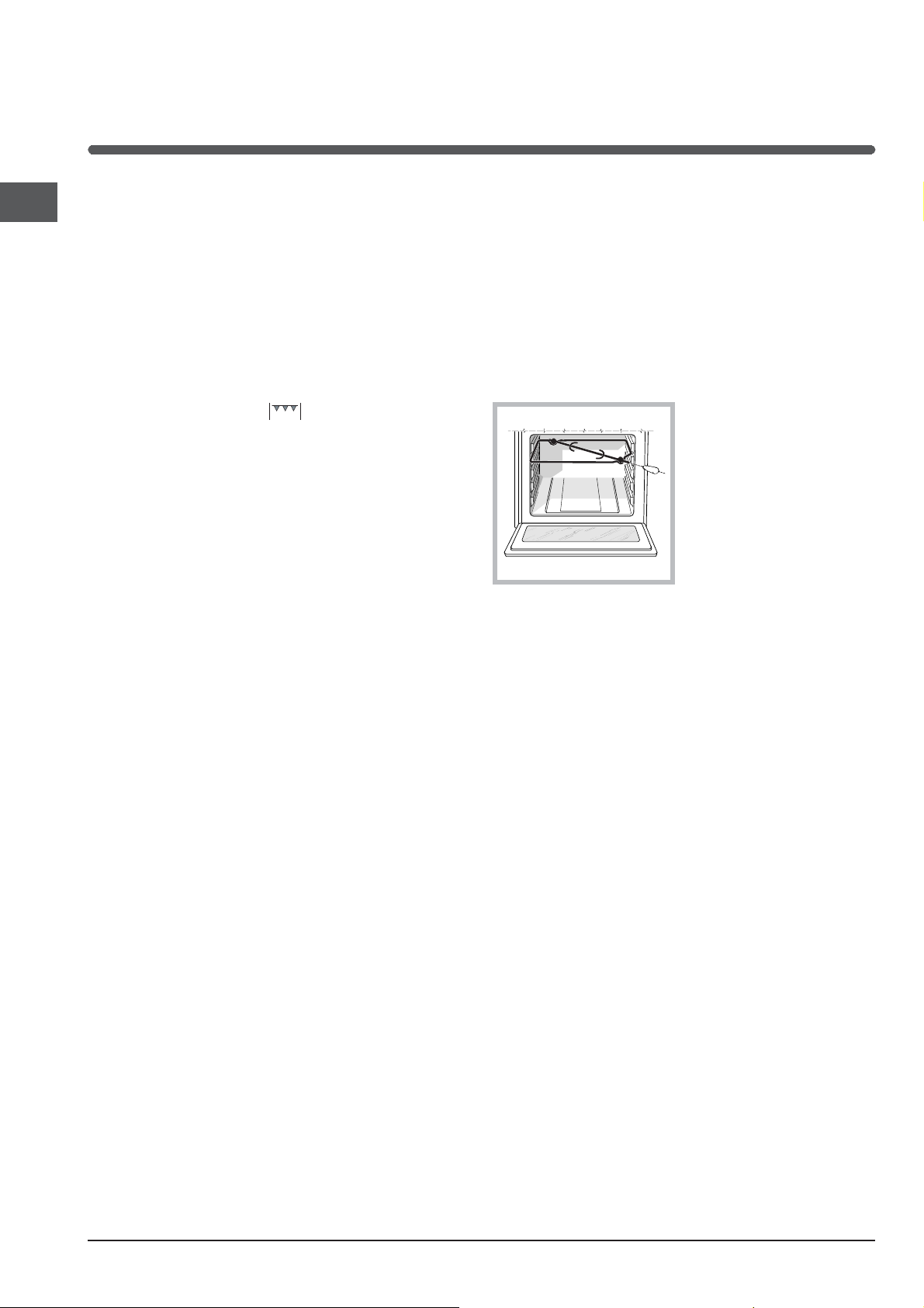
Turnspit
To operate the rotisserie (see diagram) proceed as
follows:
1. Place the dripping pan in position 1.
2. Place the rotisserie support in position 4 and insert
the spit in the hole provided on the back panel of the
oven.
3. Acitvate the function
by pressing the
TURNSPIT button.
Oven light
The light may be switched on at any moment by
pressing the OVEN LIGHT button.
Timer*
To activate the Timer proceed as follows:
1. Turn the TIMER knob in a clockwise direction 4 for
* Only available in certain models.
10
 Loading...