


INSTRUCTION MANUAL
HF/50 MHz TRANSCEIVER
i7410
FOREWORD
Thank you for making the IC-7410 your radio of choice. We hope you agree with Icom’s philosophy of “technology first.” Many hours of research and development went into the design of your IC-7410.
FEATURES
High receiver performance: third-order intercept point (IP3) of +30 dBm (HF bands only)
Simple band scope function
±0.5 ppm of high frequency stability
RTTY demodulator and decoder
RS-BA1 compatible
IMPORTANT
READ THIS INSTRUCTION MANUAL CAREFULLY before attempting to operate the
transceiver.
SAVE THIS INSTRUCTION MANUAL. This manual contains important safety and operating instructions for the IC-7410.
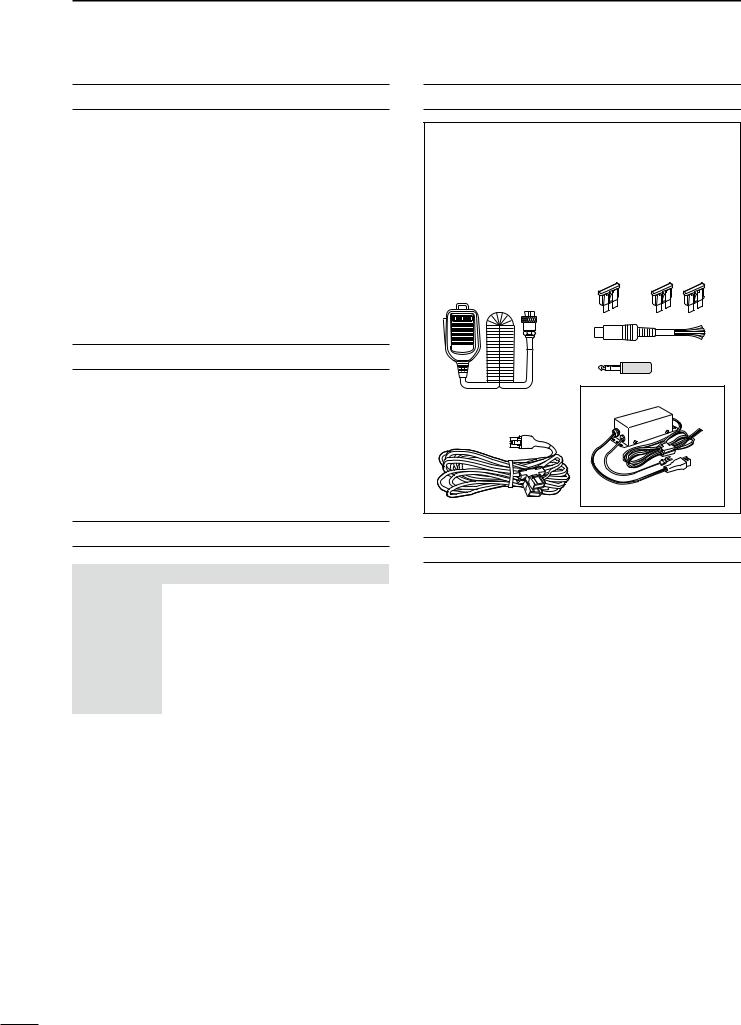
SUPPLIED ACCESSORIES
The transceiver comes with the following accessories.
|
|
Qty. |
q Hand microphone ............................................ |
|
1 |
w DC power cable* .............................................. |
|
1 |
e Spare fuse (ATC 5 A) ....................................... |
|
1 |
r Spare fuse (ATC 30 A) |
..................................... |
2 |
t ACC cable.......................................................... |
|
1 |
y 6.3 (d) mm plug................................................. |
|
1 |
* Differs depending on the version. |
|
|
q |
e |
r |
|
t |
|
|
y |
|
|
For European versions |
|
|
w |
|
w |
|
|
(see p. 19 for installation details)
EXPLICIT DEFINITIONS
WORD |
DEFINITION |
|
RDANGER! |
Personal death, serious injury or an |
|
explosion may occur. |
||
|
||
|
|
|
RWARNING! |
Personal injury, fire hazard or electric |
|
shock may occur. |
||
|
|
|
CAUTION |
Equipment damage may occur. |
|
|
|
|
NOTE |
If disregarded, inconvenience only. No risk |
|
of personal injury, fire or electric shock. |
||
|
||
|
|
Spurious signals may be received near some frequencies.
These are made in the internal circuit and does not indicate a transceiver malfunction.
Icom, Icom Inc. and the Icom logo are registered trademarks of Icom Incorporated (Japan) in Japan, the United States, the United Kingdom, Germany, France, Spain, Russia and/or other countries.
Microsoft, Windows and Windows Vista are registered trademarks of Microsoft Corporation in the United States and/or other countries.
All other products or brands are registered trademarks or trademarks of their respective holders.
FCC INFORMATION
• FOR CLASS B UNINTENTIONAL RADIATORS:
This equipment has been tested and found to comply with the limits for a Class B digital device, pursuant to part 15 of the FCC Rules. These limits are designed to provide reasonable protection against harmful interference in a residential installation. This equipment generates, uses and can radiate radio frequency energy and, if not installed and used in accordance with the instructions, may cause harmful interference to radio communications. However, there is no guarantee that interference will not occur in a particular installation. If this equipment does cause harmful interference to radio or television reception, which can be determined by turning the equipment off and on, the user is encouraged to try to correct the interference by one or more of the following measures:
•Reorient or relocate the receiving antenna.
•Increase the separation between the equipment and receiver.
•Connect the equipment into an outlet on a circuit different from that to which the receiver is connected.
•Consult the dealer or an experienced radio/TV technician for help.
CAUTION: Changes or modifications to this device, not expressly approved by Icom Inc., could void your authority to operate this device under FCC regulations.
i

PRECAUTIONS
R DANGER HIGH RF VOLTAGE! NEVER attach an antenna or internal antenna connector during transmission. This may result in an electrical shock or burn.
R WARNING! NEVER operate the transceiver with a headset or other audio accessories at high volume levels. Hearing experts advise against continuous high volume operation. If you experience a ringing in your ears, reduce the volume or discontinue use.
R WARNING! NEVER operate or touch the transceiver with wet hands. This may result in an electric shock or damage to the transceiver.
R WARNING! NEVER apply AC power to the [DC13.8V] socket on the transceiver rear panel. This could cause a fire or damage the transceiver.
R WARNING! NEVER cut the DC power cable between the DC plug and fuse holder. If an incorrect connection is made after cutting, the transceiver may be damaged.
R WARNING! NEVER apply more than 16 V DC to the [DC13.8V] socket on the transceiver rear panel, or use reverse polarity. This could cause a fire or damage the transceiver.
R WARNING! NEVER let metal, wire or other objects protrude into the transceiver or into connectors on the rear panel. This may result in an electric shock.
R WARNING! Immediately turn OFF the transceiver power and remove the power cable if it emits an abnormal odor, sound or smoke. Contact your Icom dealer or distributor for advice.
R WARNING! NEVER put the transceiver in any unstable place (such as on a slanted surface or vibrated place). This may cause injury and/or damage to the transceiver.
CAUTION: NEVER change the internal settings of the transceiver. This may reduce transceiver performance and/or damage to the transceiver.
In particular, incorrect settings for transmitter circuits, such as output power, idling current, etc., might damage the expensive final devices.
The transceiver warranty does not cover any problems caused by unauthorized internal adjustment.
CAUTION: NEVER block any cooling vents on the top, rear, sides or bottom of the transceiver.
CAUTION: NEVER expose the transceiver to rain, snow or any liquids.
CAUTION: NEVER install the transceiver in a place without adequate ventilation. Heat dissipation may be reduced, and the transceiver may be damaged.
DO NOT use harsh solvents such as benzine or alcohol when cleaning, as they will damage the transceiver surfaces.
DO NOT push the PTT switch when you don’t actually desire to transmit.
DO NOT use or place the transceiver in areas with temperatures below ±0°C (+32°F) or above +50°C (+122°F).
DO NOT place the transceiver in excessively dusty environments or in direct sunlight.
DO NOT place the transceiver against walls or putting anything on top of the transceiver. This may overheat the transceiver.
Always place unit in a secure place to avoid inadvertent use by children.
BE CAREFUL! If you use a linear amplifier, set the transceiver’s RF output power to less than the linear amplifier’s maximum input level, otherwise, the linear amplifier will be damaged.
BE CAREFUL! The rear panel will become hot when operating the transceiver continuously for long periods of time.
USE only the specified microphone. Other manufacturers’ microphones have different pin assignments, and connection to the IC-7410 may damage the transceiver or microphone.
During maritime mobile operation, keep the transceiver and microphone as far away as possible from the magnetic navigation compass to prevent erroneous indications.
Turn OFF the transceiver’s power and/or disconnect the DC power cable when you will not use the transceiver for long period of time.
1
2
3
4
5
6
7
8
9
10
11
12
13
14
15
16
17
18
19
20
21
ii

TABLE OF CONTENTS
FOREWORD............................................................... |
i |
|
IMPORTANT............................................................... |
i |
|
EXPLICIT DEFINITIONS............................................ |
i |
|
SUPPLIED ACCESSORIES....................................... |
i |
|
FCC INFORMATION................................................... |
i |
|
PRECAUTIONS......................................................... |
ii |
|
TABLE OF CONTENTS............................................ |
iii |
|
1 |
PANEL DESCRIPTION................................... |
1–14 |
|
■ Front panel......................................................... |
1 |
|
■ Rear panel......................................................... |
8 |
|
D ACC socket information............................... |
10 |
|
■ LCD display...................................................... |
11 |
|
■ Function display............................................... |
13 |
|
D M1 (Menu 1)................................................ |
13 |
|
D Function keys on M1 (Menu 1).................... |
13 |
|
D M2 (Menu 2)................................................ |
14 |
|
D Function keys on M2 (Menu 2).................... |
14 |
|
■ Selecting a location.......................................... |
15 |
|
■ Grounding........................................................ |
15 |
2 |
INSTALLATION AND CONNECTIONS........ |
15–22 |
|
■ Antenna connection......................................... |
15 |
|
■ Required connections...................................... |
16 |
|
D Front panel.................................................. |
16 |
|
D Rear panel................................................... |
16 |
|
■ Advanced connections..................................... |
17 |
|
D Front panel.................................................. |
17 |
|
D Rear panel................................................... |
17 |
|
■ External keypad connections........................... |
18 |
|
■ External antenna tuner connection.................. |
18 |
|
D Connecting the AH-4................................... |
18 |
|
■ Power supply connections............................... |
19 |
|
■ Connecting to a DC power supply................... |
19 |
|
D Connecting to the PS-126 DC POWER |
|
|
SUPPLY....................................................... |
19 |
|
D Connecting to a non-Icom DC POWER |
|
|
SUPPLY....................................................... |
19 |
|
■ Linear amplifier connections............................ |
20 |
|
D Connecting the IC-PW1/PW1EURO........... |
20 |
|
D Connecting a non-Icom linear amplifier....... |
21 |
|
■ Microphone connector information.................. |
22 |
|
■ Microphones.................................................... |
22 |
|
D HM-36.......................................................... |
22 |
|
D SM-50 (option)............................................. |
22 |
3 BASIC OPERATION..................................... |
23–34 |
■ Before first applying power.............................. |
23 |
■ Turning ON (CPU resetting)............................. |
23 |
■ VFO description............................................... |
24 |
D Selecting the VFO A/B................................ |
24 |
D VFO equalization........................................ |
24 |
■ Selecting VFO/Memory mode.......................... |
24 |
■ Selecting a frequency band............................. |
25 |
D Using the band stacking registers................ |
25 |
■ Frequency setting............................................ |
26 |
D Tuning with [DIAL]....................................... |
26 |
D Direct frequency entry with the keypad....... |
26 |
D Quick Tuning function.................................. |
27 |
D Selecting 1 Hz step..................................... |
27 |
D 1⁄4 Tuning Step function............................... |
27 |
D Auto Tuning Step function........................... |
28 |
D About the 5 MHz frequency band operation |
|
(USA version only)...................................... |
28 |
D Band edge warning beep............................ |
29 |
D Programming the user band edge............... |
30 |
■ Operating mode selection................................ |
31 |
■ Volume setting.................................................. |
31 |
■ Squelch and receive (RF) sensitivity................ |
32 |
■ Voice synthesizer operation............................. |
33 |
■ Meter Display selection.................................... |
33 |
■ Basic transmit operation.................................. |
34 |
D Transmitting................................................. |
34 |
D Microphone gain adjustment....................... |
34 |
iii

4 RECEIVE AND TRANSMIT........................... |
35–52 |
■ Operating SSB................................................. |
35 |
■ Operating CW.................................................. |
36 |
D About the CW reverse mode....................... |
37 |
D About CW pitch control................................ |
37 |
D About keying speed..................................... |
37 |
D CW sidetone function.................................. |
37 |
■ Electronic keyer functions................................ |
38 |
D Memory keyer menu construction............... |
38 |
D Memory keyer send menu........................... |
39 |
D Editing a memory keyer............................... |
40 |
D Contest number Set mode........................... |
41 |
D Keyer Set mode........................................... |
42 |
■ Operating RTTY (FSK).................................... |
44 |
■ RTTY functions................................................ |
45 |
D RTTY menu construction............................. |
45 |
D About the RTTY reverse mode.................... |
46 |
D RTTY decoder............................................. |
46 |
D Twin Peak Filter............................................ |
47 |
D RTTY Set mode........................................... |
48 |
■ Operating AM/FM............................................ |
49 |
Tone squelch operation................................... |
50 |
■ Tone scan operation......................................... |
51 |
Repeater operation.......................................... |
51 |
D Repeater access tone frequency setting..... 52 |
|
D Transmit frequency monitor check.............. |
52 |
5 |
FUNCTIONS FOR RECEIVE........................ |
53–61 |
|
■ RIT function..................................................... |
53 |
|
D RIT Monitor function.................................... |
53 |
|
■ Simple band scope.......................................... |
54 |
|
■ Preamplifier...................................................... |
55 |
|
■ Attenuator........................................................ |
55 |
|
■ AGC function................................................... |
56 |
|
D AGC speed selection................................... |
56 |
|
D Setting the AGC time constant.................... |
56 |
|
■ IF filter selection............................................... |
57 |
|
D IF filter selection.......................................... |
57 |
|
D Filter passband width setting....................... |
57 |
|
D 1st IF filter selection..................................... |
58 |
|
D IF (DSP) filter shape.................................... |
58 |
|
■ Twin PBT operation.......................................... |
59 |
|
■ Noise Blanker................................................... |
60 |
|
D NB Set mode............................................... |
60 |
|
■ Meter Peak Hold function................................. |
60 |
|
■ Noise Reduction.............................................. |
61 |
|
■ Dial Lock function............................................. |
61 |
|
■ Notch function.................................................. |
61 |
6 |
FUNCTIONS FOR TRANSMIT...................... |
62–68 |
|
■ VOX function.................................................... |
62 |
|
D Using the VOX function................................ |
62 |
|
D Adjusting the VOX function.......................... |
62 |
|
■ Break-in function.............................................. |
63 |
|
D Semi Break-in operation.............................. |
63 |
|
D Full Break-in operation................................ |
63 |
|
■ Speech Compressor........................................ |
64 |
|
■ Transmit filter width selection............................. |
64 |
|
■ ∂TX function.................................................... |
65 |
|
D ∂TX Monitor function................................... |
65 |
|
■ Monitor function............................................... |
65 |
|
■ Split frequency operation................................. |
66 |
|
■ Quick Split function.......................................... |
67 |
|
D Split Lock function....................................... |
67 |
|
■ Measuring SWR............................................... |
68 |
|
D Spot measurement...................................... |
68 |
|
D Plot measurement....................................... |
68 |
1
2
3
4
5
6
7
8
9
10
11
12
13
14
15
16
17
18
19
20
21
iv

TABLE OF CONTENTS
7 |
MEMORY OPERATION................................. |
69–74 |
|
■ General description.......................................... |
69 |
|
D Memory channel contents........................... |
69 |
|
■ Memory channel selection............................... |
69 |
|
D Selection in the VFO mode.......................... |
69 |
|
D Selection in the Memory mode.................... |
69 |
|
■ Memory channel programming........................ |
70 |
|
D Programming in the VFO mode................... |
70 |
|
D Programming in the Memory mode............. |
70 |
|
■ Memory clearing.............................................. |
71 |
|
■ Memory contents copying................................ |
72 |
|
D Copying in the VFO mode........................... |
72 |
|
D Copying in the Memory mode...................... |
72 |
|
■ Memory name programming............................ |
73 |
|
■ Memo Pad function.......................................... |
74 |
|
D Writing the displayed data into a memo pad.. 74 |
|
|
D Calling up a memo pad................................ |
74 |
|
■ Scan types....................................................... |
75 |
8 |
SCANS.......................................................... |
75–81 |
|
■ Preparation...................................................... |
76 |
|
■ Voice Squelch Control function........................ |
76 |
|
■ Scan Set mode................................................ |
77 |
|
■ Programmed scan/Fine programmed scan |
|
|
(VFO mode)..................................................... |
78 |
|
D About the Fine programmed scan............... |
78 |
|
■ Memory scan (Memory mode)......................... |
79 |
|
D Memory scan............................................... |
79 |
|
D Select Memory scan.................................... |
80 |
|
D Setting/Cancelling Select Memory channels.. 80 |
|
|
■ ∂F scan and Fine ∂F scan.............................. |
81 |
|
D About the Fine ∂F scan............................... |
81 |
9 ANTENNA TUNER OPERATION.................. |
82–84 |
■ Antenna connection and selection................... |
82 |
■ Antenna tuner operation.................................. |
83 |
D Tuner operation........................................... |
83 |
D Manual tuning.............................................. |
83 |
■ Optional external tuner operation..................... |
84 |
10 SET MODE.................................................... |
85–91 |
■ Set mode description....................................... |
85 |
D The Set mode settings................................. |
85 |
■ Tone Control Set mode description.................. |
90 |
D The Tone control Set mode settings............ |
90 |
11 DATA COMMUNICATION............................. |
92–93 |
■ Connections..................................................... |
92 |
D When connecting to [ACC].......................... |
92 |
D When connecting to [MIC]........................... |
92 |
■ Packet (AFSK) operation................................. |
93 |
D Frequency display during AFSK operation.. 93 |
|
12 OPTION INSTALLATION.............................. |
94–95 |
■ Opening the transceiver’s case........................ |
94 |
■ FL-430/FL-431 1st if filter installation.......... |
95 |
13 MAINTENANCE.......................................... |
96–100 |
■ Troubleshooting................................................ |
96 |
D Transceiver power........................................ |
96 |
D Transmit and receive.................................... |
96 |
D Scanning..................................................... |
97 |
D Display......................................................... |
97 |
■ Dial tuning tension adjustment......................... |
97 |
■ Frequency calibration (approximate)................ |
98 |
■ About protection displays................................. |
98 |
■ Fuse replacement............................................ |
99 |
D DC power cable fuse replacement.............. |
99 |
D Circuitry fuse replacement.......................... |
99 |
■ Resetting the CPU......................................... |
100 |
D Partial reset............................................... |
100 |
D All reset..................................................... |
100 |
v

14 CONTROL COMMAND............................. |
101–108 |
■ Remote jack (CI-V) information...................... |
101 |
D CI-V connection example.......................... |
101 |
D Data format................................................ |
101 |
D Command table......................................... |
102 |
D Data content description............................ |
106 |
■ General.......................................................... |
109 |
■ Transmitter..................................................... |
109 |
15 SPECIFICATIONS..................................... |
109–110 |
■ Receiver......................................................... |
110 |
■ Antenna tuner................................................ |
110 |
16 OPTIONS.................................................. |
111–112 |
■ Options.......................................................... |
111 |
17 CE.............................................................. |
113–114 |
1
2
3
4
5
6
7
8
9
10
11
12
13
14
15
16
17
18
19
20
21
vi
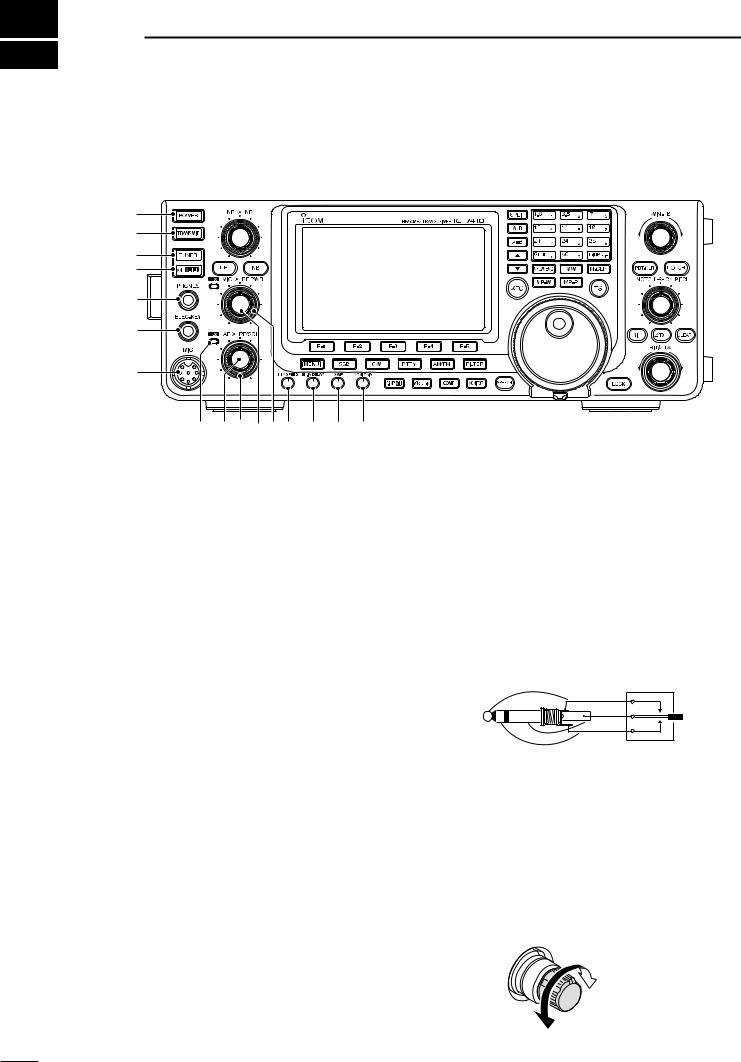
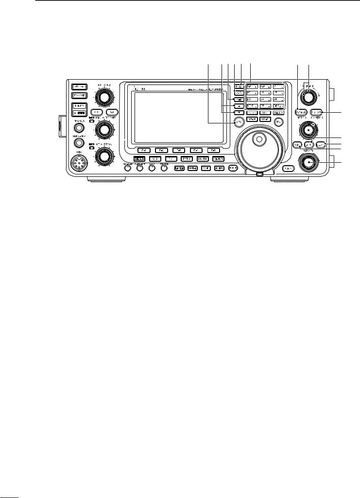
1 PANEL DESCRIPTION
■ Front panel
q w
e r
t 
y
u
i o !0!1!2!3!4!5!6
q POWER SWITCH [POWER] (p. 23)
Push to turn ON the transceiver power.
• First, confirm the DC power source is turned ON.
Hold down for 1 second to turn OFF the power.
w TRANSMIT SWITCH [TRANSMIT] (p. 34) Push to select transmit or receive.
•While transmitting, the TX indicator (@1) lights red.
•While receiving or when the squelch opens, the RX indicator (i) lights green.
e ANTENNA TUNER SWITCH [TUNER] (pp. 83, 84)
Push to turn the internal antenna tuner ON or OFF (bypass).
• When the tuner is ON, “ ” appears.
• The internal antenna tuner settings can be memorized in each frequency band.
Hold down for 1 second to manually start the antenna tuner.
• If the tuner cannot tune the antenna within 20 seconds, the tuning circuit is automatically bypassed.
r ANTENNA•METER SWITCH [ANT•METER]
ANTENNA SWITCH Operation
Push to select either the ANT1 or ANT2 connector. (p. 82)
METER SWITCH Operation
Hold down for 1 second to display either the COMP or SWR meter in addition to the ALC meter. (p. 33)
t HEADPHONE JACK [PHONES] (p. 17)
Plug in standard stereo headphones. Impedance: 8 to 16 ø.
• Output power: 5 mW with an 8 ø load.
• When headphones are connected, the internal speaker, and any external speaker, are disabled.
y ELECTRONIC KEYER JACK [ELEC-KEY]
Plug in a bug or paddle type key to use the internal electronic keyer for CW operation. (p. 16)
• Select the ELEC-KEY, BUG KEY or Straight key keyer type in the “Keyer Type” item of the Keyer Set mode.
• When a straight key is connected, “Straight key” must be selected in the “Keyer Type” item of the Keyer Set mode. (p. 43)
• A straight key jack is located on the rear panel. See
[KEY] on pages 8 and 16.
• You can reverse the keyer paddle polarity (dot and dash) in the “Paddle Polarity” item of the Keyer Set mode. (p. 42)
• Four keyer memory channels are available for your convenience. (p. 40)
(dot)
(com)
(dash)
u MICROPHONE CONNECTOR [MIC]
Plug in the supplied or optional microphone.
• See page 22 for appropriate microphones and microphone connector information.
i RX INDICATOR
Lights green while receiving or when the squelch opens.
o AF CONTROL [AF] (inner control; p. 31)
Rotate to adjust audio output level to the speaker or headphones.
Increases
Decreases
1
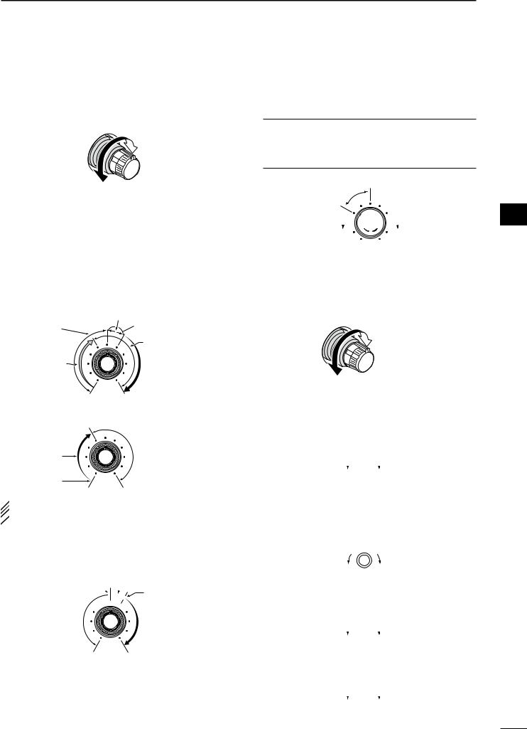
!0RF GAIN CONTROL/SQUELCH CONTROL [RF/SQL] (outer control; p. 32)
Rotate to adjust the RF gain and squelch threshold level.
The squelch removes noise output to the speaker when no signal is received (closed condition).
•The squelch is particularly effective in FM, but also works in other modes.
•The 12 to 1 o’clock position is recommended for the most effective use of the [RF/SQL] control.
•[RF/SQL] operates as only an RF gain control in SSB,
CW and RTTY (Squelch is fixed open), or a squelch control in AM and FM (RF gain is fixed at maximum sensitivity), when the “RF/SQL Control” item is set to “Auto” in the Set mode. (p. 86)
•When used as an RF gain/squelch control
Noise squelch (FM mode)
Squelch is |
Recommended level |
|
|
||
open. |
Maximum |
|
|
||
|
RF gain |
|
RF gain |
|
|
adjustable |
S-meter |
|
range |
||
squelch |
||
|
•When used as an RF gain control
(Squelch is fixed open; SSB, CW and RTTY only)
Adjustable |
Maximum |
RF gain |
|
range |
|
Minimum RF gain |
|
 While rotating the RF gain control, a faint noise may
 be heard. This comes from the DSP unit and does
  not indicate an equipment malfunction.
•When used as a squelch control
(RF gain is fixed at maximum.)
Noise squelch (FM mode)
Noise squelch
 threshold
 (FM mode)


Squelch is open.
Shallow
S-meter squelch threshold
S-meter squelch
Deep
PANEL DESCRIPTION |
1 |
!1MIC GAIN CONTROL [MIC] (inner control; p. 34) Rotate to adjust the microphone gain.
• The transmit audio tone in the SSB, AM and FM modes can be independently adjusted in the Tone Control Set mode. (pp. 90, 91)
How to set the microphone gain.
While speaking at normal voice level, adjust the microphone gain so that in the SSB or AM modes, the ALC meter swings within the ALC zone.
Recommended level for
Icom microphones
Decreases 


 Increase
!2RF POWER CONTROL [RF PWR]
(outer control; p. 34)
Rotate to continuously vary the RF output power between 2 W (minimum) and 100 W (maximum). (AM: between 2 W and 27 W).
!3ELECTRONIC CW KEYER SPEED CONTROL [KEY SPEED] (p. 37)
(Mode: CW)
Rotate to adjust the keying speed of the internal electronic CW keyer to between 6 wpm (minimum) and 48 wpm (maximum).
Slow 

 Fast
Fast
!4BREAK IN DELAY CONTROL [BK-IN DELAY]
(p. 63)
(Mode: CW)
Rotate to adjust the transmit-to-receive switching delay time for the Semi Break-in function.
Short delay |
|
Long delay for |
for high speed |
|
slow speed |
|
||
keying |
|
keying |
!5COMPRESSOR CONTROL [COMP] (p. 64)
(Mode: SSB)
Rotate to adjust the compression level.
Decreases 

 Increases
!6MONITOR GAIN CONTROL [MONI GAIN] (p. 65)
Rotate adjust the monitor level for the clearest
audio output.
Decreases 

 Increases
1
2
3
4
5
6
7
8
9
10
11
12
13
14
15
16
17
18
19
20
21
2
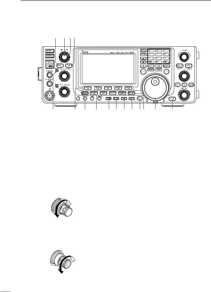
1 PANEL DESCRIPTION
Front panel (continued)
@0 !9!8!7
@1 |
@2 @3 @4 |
@5@6 @7@8 @9#0 #1 |
#2 |
!7NOISE BLANKER SWITCH [NB] (p. 60)
Push to turn the Noise Blanker ON or OFF. The Noise Blanker reduces pulse-type noise such as that generated by vehicle ignition systems. The Noise Blanker cannot be used in the FM mode,
and is not effective for non-pulse-type noise.
• “NB” appears when the Noise Blanker is ON.
Hold down for 1 second to display the “NB” screen. Push to return to the previous screen display.
!8NOISE BLANKER LEVEL CONTROL [NB]
(outer control; p. 60)
Rotate to adjust the noise blanker threshold level when the Noise Blanker is ON. Set for maximum readability.
• To use this control, first push [NB] (!7).
 Increases
Decreases
!9NOISE REDUCTION LEVEL CONTROL [NR]
(inner control; p. 61)
Rotate to adjust the DSP noise reduction level when the Noise Reduction is ON. Set for maximum readability.
• To use this control, first push [NR] (@0).
 Increases
Decreases
@0NOISE REDUCTION SWITCH [NR] (p. 61) Push to turn DSP Noise Reduction ON or OFF.
• “NR” appears when Noise Reduction is ON.
@1TX INDICATOR
Lights red while transmitting.
@2FUNCTION SWITCHES [F1]–[F5] (pp. 13, 14) Push to select the function which is indicated on the LCD display above each switch.
•The functions vary, depending on the selected menu and the operating mode.
@3MENU SWITCH [MENU] (pp. 13, 14)
Push to change the set of functions assigned to switches ([F-1] to [F-5]).
•Toggles between the function menus, M1 (Menu 1) and M2 (Menu 2).
Hold down for 1 second to enter the Set mode. Push to return to the previous screen display.
@4MODE SWITCHES
Push to select your desired operating mode. (p. 31)
• The built-in speech synthesizer announces the selected mode when the “SPEECH [MODE] SW” item is set to “ON” in the Set mode. (p. 87)
[SSB]
Push to alternately select the USB or LSB modes.
• “USB” or “LSB” appears.
In the SSB mode, hold down for 1 second to select the SSB data mode (USB-D, LSB-D).
• “D” appears in addition to “USB” or “LSB.”
In the SSB data mode, push to return to the normal SSB mode.
[CW]
Push to alternately select the CW and CW-R (CW reverse) modes.
• “CW” or “CW-R” appears.
3
[RTTY]
Push to alternately select the RTTY and RTTY-R (RTTY reverse) modes.
• “RTTY” or “RTTY-R” appears.
[AM/FM]
Push to alternately select the AM or FM modes.
• “AM” or “FM” appears.
Hold down for 1 second to select the AM or FM data mode (AM-D/FM-D).
• “D” appears in addition to “AM” or “FM.”
In the data mode, push to return to the normal AM or FM mode.
@5PREAMP•ATTENUATOR SWITCH [P.AMP•ATT]
PREAMP SWITCH Operation (p. 55)
Push to select one of two receive RF preamplifiers, or to bypass them.
• “P. AMP ” is a wide dynamic range preamplifier. It is most effective for the 1.8 to 21 MHz bands.
• “P. AMP ” is a high-gain preamplifier. It is most effective for the 24 to 50 MHz bands.
• No indicator appears when the preamplifiers are not selected.
What is the preamplifier?
The preamplifier amplifies signals in the front end to improve the S/N ratio and sensitivity. Select “P. AMP ” or “P. AMP
 ” when receiving weak signals.
ATTENUATOR SWITCH Operation (p. 55)
Hold down for 1 second to turn ON the attenuator.
•“ATT” appears when the attenuator is ON.
Push to turn OFF the attenuator.
•“ATT” disappears.
What is the attenuator?
The attenuator prevents a desired signal from being distorted when very strong signals are near it, or when very strong electromagnetic fields, such as from a broadcasting station, are near your location.
@6VOX/BK-IN SWITCH [VOX/BK-IN]
VOX SWITCH Operation (p. 62)
(Mode: SSB/AM/FM)
Push to turn the VOX function ON or OFF. Hold down for 1 second to display the “VOX”
screen. Push to return to the previous screen display.
What is the VOX function?
The VOX function (voice operated transmission) automatically starts transmission when you speak into the microphone; then automatically returns to receive when you stop speaking.
PANEL DESCRIPTION |
1 |
BK-IN SWITCH Operation (p. 63)
(Mode: CW)
Push to toggle the Break-in function between semi break-in and full break-in, or to turn OFF the function.
What is the Break-in function?
The Break-in function automatically switches between transmit and receive with your CW keying. Using the Full Break-in function (QSK), you can hear the receive frequency in-between keying.
@7COMPRESSOR SWITCH [COMP] (p. 64)
(Mode: SSB)
Push to turn the Speech Compressor function ON or OFF.
• “COMP” appears when this function is ON.
@8MONITOR SWITCH [MONITOR] (p. 65)
Push to turn the Monitor function ON or OFF to listen to your own transmitted audio.
• “MONI” appears when this function is ON.
• In the CW mode, the CW sidetone can be heard, regardless of the [MONITOR] switch setting.
@9SPEECH SWITCH [SPEECH] (p. 33)
Push to audibly announce the S-meter level and the displayed frequency.
Hold down for 1 second to audibly announce the S-meter level, the displayed frequency, and the operating mode.
• The S-Level announcement can be turned OFF in the
“SPEECH S-Level” item of the Set mode. (p. 87)
•When RIT and/or ∂TX are ON, the RIT/∂TX offset is not included in the frequency announcement.
#0FILTER SWITCH [FILTER] (p. 57)
Push to select one of three IF filter settings ( /
/ /
/  ).
).
•The selected filter passband width and shifting value are displayed for 2 seconds on the LCD display.
Hold down for 1 second to display the “FIL” screen (Filter) to set the filter passband width. Hold down for 1 second again to return to the previous screen display.
#1TUNING DIAL [DIAL] (p. 26)
Rotate to change the operating frequency, select the Set mode settings, etc.
#2LOCK SWITCH [LOCK] (p. 61)
Push to turn the Dial Lock function ON or OFF.
•This function electronically locks [DIAL].
•“ ” appears when this function is ON.
1
2
3
4
5
6
7
8
9
10
11
12
13
14
15
16
17
18
19
20
21
4
1 PANEL DESCRIPTION
Front panel (continued)
#83#4#5#6#7#8
#9$0
$1


 $2
$2 

 $3
$3
$4 |
$5 |
$6 |
$7
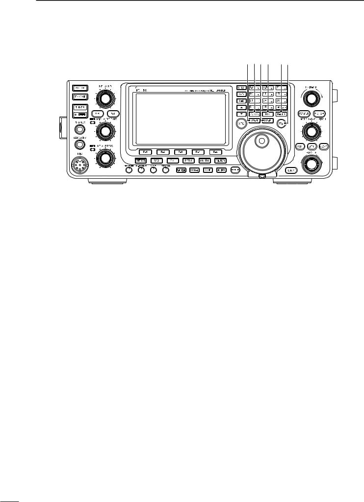
#3TRANSMIT FREQUENCY CHECK SWITCH [XFC]
During split frequency or repeater operation, hold down to listen to the transmit frequency. (pp. 52, 56)
• While holding down this switch, the transmit frequency can be changed with [DIAL], keypad or memo pad.
• When the Split Lock function is turned ON, push
[XFC] to cancel the Dial Lock function. (p. 67)
When the RIT function is turned ON, hold down to listen to the displayed frequency (RIT is temporarily cancelled). (p. 53)
When the ∂TX function is turned ON, hold down to listen to the transmit frequency (including ∂TX frequency offset). (p. 65)
#4UP/DOWN SWITCHES [Y]/[Z]
Push to change the operating channel. (p. 69)
Hold down to continuously change the operating channel.
#5VFO EQUALIZE SWITCH [A=B] (p. 24)
Hold down for 1 second to equalize frequencies of VFO A and B.
#6VFO SELECT SWITCH [A/B] (p. 24)
Push to select either VFO A or VFO B to display.
• “VFOA” or “VFOB” is displayed, depending on the selection.
#7SPLIT SWITCH [SPLIT]
Push to turn the Split function ON or OFF. (p. 66)
• “SPLIT” appears when the Split function is ON.
Hold down for 1 second to activate the Quick Split function. (p. 67)
• The transmit frequency shifts from the receive frequency according to the “FM SPLIT Offset HF/50” setting in the Set mode. (p. 86)
• The Quick Split function can be turned OFF in the
“Quick SPLIT” item of the Set mode. (p. 86)
#8BAND KEYS/KEYPAD
BAND KEYS Operation (p. 25)
Push to select the operating band.
• [GENE •] selects the general coverage band.
Pushing the same key two or three times calls up other stacked frequencies in the frequency band.
•Icom’s triple band stacking register memorizes three frequencies in each frequency band.
KEYPAD Operation (p. 26)
After pushing [F-INP ENT], push the keys on the keypad to enter a frequency. After entering, push [F-INP ENT] to set the frequency.
•Example; to enter 14.195 MHz:
Push [F-INP ENT] [1] [4] [•] [1] [9] [5] [F-INP ENT].
#9PBT CLEAR SWITCH [PBT-CLR] (p. 59)
(Mode: SSB/CW/RTTY/AM)
Push to display the filter passband width and shifting value for 2 seconds on the function display.
Hold down for 1 second to reset the PBT settings.
$0PASSBAND TUNING CONTROLS [TWIN-PBT]
(p. 59)
(Mode: SSB/CW/RTTY/AM)
Adjusts the receiver’s IF filter passband width using the DSP circuit.
• Rotate this control or push [PBT-CLR] to display the PBT settings (passband width and shifting value) for 2 seconds on the function display.
• Hold down [PBT-CLR] for 1 second to clear the PBT settings.
• The adjustment range is half of the passband width, and the value is adjustable in 25 Hz steps in the SSB, CW, and RTTY modes, and 100 Hz steps in the AM mode.
• These controls function as an IF shift control.
5
What is the PBT control?
The PBT function electronically modifies the IF passband width to reject interference. This transceiver uses the DSP circuit for the PBT function.
PBT2

 PBT1
PBT1
– |
+ |
High cut |
Center |
Low cut |
$1NOTCH SWITCH [NOTCH] (p. 61)
(Mode = Auto notch : SSB/AM/FM Manual notch: SSB/CW/RTTY/AM)
In the SSB and AM modes, push to toggle the notch function between auto, manual and OFF.
•Either the Auto or Manual Notch function can be turned OFF in the “[NOTCH] SW” item of the Set mode. (p. 88)
In the FM mode, push to turn the Auto Notch function ON or OFF.
In the CW or RTTY mode, push to turn the Manual Notch function ON or OFF.
• “MNF” appears when the Manual Notch function is
ON.
• “ANF” appears when the Auto Notch function is ON. • No icon appears when the Notch function is OFF.
Hold down for 1 second to switch the manual filter characteristics from wide, mid and narrow when the Manual Notch function is selected.
What is the notch filter?
The notch filter is a narrow filter that eliminates unwanted CW or AM carrier tones, while preserving the desired voice signal. The DSP circuit automatically adjusts the notch frequency to effectively eliminate unwanted tones.
$2MANUAL NOTCH FILTER CONTROL [NOTCH]
(inner control; p. 61)
Rotate to adjust the notch frequency to reject an interfering signal when the Manual Notch function is ON.
• Notch filter center frequency:
SSB/RTTY |
: –1040 Hz to +4040 Hz |
CW |
: CW pitch freq. –2540 Hz to |
|
CW pitch freq. +2540 Hz |
AM |
: –5060 Hz to +5100 Hz |
|
Higher frequency |
Lower frequency
PANEL DESCRIPTION |
1 |
$3CW PITCH CONTROL [CW PITCH]
(outer control; p. 37)
Rotate to shift the received CW audio pitch and the CW sidetone pitch without changing the operating frequency.
•The pitch can be adjusted from 300 to 900 Hz in approximately 5 Hz steps.
Higher pitch
Lower pitch
$4∂TX SWITCH [∂TX] (p. 65)
Push to turn the ∂TX function ON or OFF.
• Use the [RIT/∂TX] control to vary the ∂TX frequency.
Hold down for 1 second to shift the transmit frequency up or down by the ∂TX frequency shift.
What is the ∂TX function?
∂TX shifts the transmit frequency without shifting the receive frequency. This is useful for simple split frequency operation in CW, etc.
$5CLEAR SWITCH [CLEAR] (pp. 53, 65)
Hold down for 1 second* to clear the RIT/∂TX frequency shift.
*When the “Quick RIT Clear” item in the Set mode is set to “ON,” push momentarily to reset the frequency shift. (p. 88)
$6RIT SWITCH [RIT] (p. 53)
Push to turn the RIT function ON or OFF.
• Use [RIT/∂TX] control to vary the RIT frequency.
Hold down for 1 second to shift the receive frequency up or down by the RIT frequency shift.
What is the RIT function?
The RIT (Receiver Incremental Tuning) shifts the receive frequency without shifting the transmit frequency.
This is useful for fine tuning stations calling you off-fre- quency or when you prefer to listen to slightly differentsounding voice characteristics, etc.
$7RIT/∂TX CONTROL [RIT/∂TX] (pp. 53, 65)
When either or both the RIT/∂TX functions are ON, rotate to adjust the RIT/∂TX frequency shift.
• Rotate the control clockwise to increase the frequency, or counterclockwise to decrease the frequency.
• The frequency shift range is ±9.999 kHz in 10 Hz steps.
The control tunes in 1 Hz steps when the operating frequency readout is set to the 1 Hz step readout.
Shift high
Shift low
1
2
3
4
5
6
7
8
9
10
11
12
13
14
15
16
17
18
19
20
21
6
1 PANEL DESCRIPTION
Front panel (continued)
$8MEMO PAD-WRITE SWITCH [MP-W] (p. 74) Push to write the displayed data into a memo pad.
• The five most recent entries remain in the memo pads. • The memo pad capacity can be extended from 5 to
10 in the “Memopad Numbers” item in the Set mode. (p. 87)
$9VFO/MEMORY SWITCH [VFO/MEMO]
Push to switch between the VFO and Memory modes. (p. 24)
Hold down for 1 second to transfer the memory contents to the displayed VFO. (p. 72)
%0MEMO PAD-READ SWITCH [MP-R] (p. 74)
Push to sequentially call up the contents from the memo pads.
The 5 (or 10) most recently programmed frequencies and operating modes can be recalled, starting from the most recent.
•The memo pad capacity can be extended from 5 to
10 in the “Memopad Numbers” item in the Set mode. (p. 87)
%1MEMORY WRITE SWITCH [MW] (p. 70)
Hold down for 1 second to store VFO data into the selected memory channel.
• This can be done in both the VFO and memory modes.
%2MEMORY CLEAR SWITCH [M-CLR] (p. 71)
In the Memory mode, hold down for 1 second to clear the memory channel.
•The channel becomes a blank channel.
•This switch is disabled in the VFO mode.
$8$9%0%1 %2%3
%3TUNING STEP SWITCH [TS] (p. 27)
Push to turn quick tuning step ON or OFF.
• When the “” quick tuning icon is displayed above the kHz digit, the frequency is changed in selected quick tuning steps.
• When the quick tuning is OFF, the frequency is changed in 10 Hz steps.
When the quick tuning is ON, hold down for 1 second to display the “TS” screen (Tuning Step) to select the quick tuning step.
• 0.1, 1, 5, 9, 10, 12.5, 20, and 25 kHz steps are independently selectable for each operating mode.
When the quick tuning is OFF, hold down for 1 second to turn the minimum tuning step of 1 Hz ON or OFF.
7
PANEL DESCRIPTION |
1 |
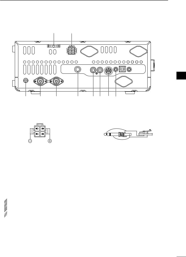
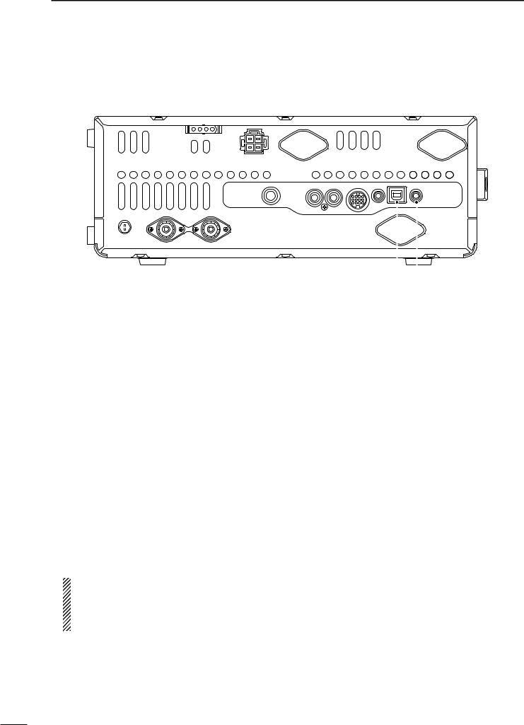
■ Rear panel
w q
e |
r |
t |
y |
q DC POWER SOCKET [DC 13.8V] (p. 19) Connect 13.8 V DC through the supplied DC power cable.
Rear panel view
w TUNER CONTROL SOCKET [TUNER] (p. 18) Connect the control cable from an optional AH-4 hf/
50 mhz automatic antenna tuner.
e GROUND TERMINAL [GND] (p. 15)
Connect this terminal to a ground to prevent electrical shocks, TVI, BCI and other problems.
r ANTENNA CONNECTOR 1 [ANT1] (p. 16) t ANTENNA CONNECTOR 2 [ANT2] (p. 16)
Connect a 50 ø antenna with a PL-259 plug connector.
 When using an optional AH-4 hf/ 50 mhz auto- matic antenna tuner, connect it to the [ANT1] connector. Connecting the AH-4 activates the in-
  ternal antenna tuner for [ANT2] and deactivates
 it for [ANT1].
u i o !0
y STRAIGHT KEY JACK [KEY] (p. 16)
Connect a straight key or external electronic keyer output using a standard 1⁄4 inch plug.
• To use the internal electronic keyer for CW operation, connect to [ELEC-KEY] on the front panel. (p. 1)
(+)
(_)
u ALC INPUT JACK [ALC] (p. 21)
When transmitting, goes to ground to control an external unit, such as a non-Icom linear amplifier.
i SEND CONTROL JACK [SEND] (p. 21)
Connect a ground when transmitting to control an external unit, such as a non-Icom linear amplifier.
o ACCESSORY SOCKET [ACC]
Connect control lines for external equipment such as a linear amplifier, an automatic antenna selector/ tuner, a TNC for data communications, etc.
• See page 10 for socket information.
!0CI-V REMOTE CONTROL JACK [REMOTE]
(p. 17)
Connect a PC, using the optional CT-17 ci-v level converter, for external control of the transceiver.
Use for transceive operation with another Icom CI-V transceiver or receiver. When the transceive function is set to ON, changing the frequency, operating mode, etc. on the IC-7410 automatically changes those settings on other Icom transceivers or receivers, and vice versa. (p. 89)
1
2
3
4
5
6
7
8
9
10
11
12
13
14
15
16
17
18
19
20
21
8
1 PANEL DESCRIPTION
Rear panel (Continued)
|
|
|
|
|
|
|
|
|
|
|
|
|
|
|
|
|
|
|
|
|
|
|
|
|
|
|
|
|
|
|
|
|
|
|
|
|
|
|
|
|
|
|
|
|
|
|
|
|
|
|
|
|
|
|
|
|
|
|
!1 |
!2 |
|
|||
!1USB (Universal Serial Bus) CONNECTOR [USB] |
|
!2EXTERNAL SPEAKER JACK [EXT-SP] (p. 17) |
||||||||||
Using a USB cable, connect a PC to do the follow- |
|
Connect an external speaker (4 to 8 ø). |
||||||||||
ing: |
|
|
|
|
|
|
||||||
- Input modulation (p. 89) |
|
|
|
|
|
|
||||||
- Remotely control the transceiver using CI-V com- |
|
|
|
|
|
|
||||||
mands (p. 101) |
|
|
|
|
|
|
||||||
- Send the received audio to the PC |
|
|
|
|
|
|
||||||
- Send the decoded characters to the PC (p. 89) |
|
|
|
|
|
|
||||||
About the USB driver: |
|
|
|
|
|
|
||||||
The USB driver and the installation guide can be |
|
|
|
|
|
|
||||||
downloaded from our website. |
|
|
|
|
|
|
||||||
http://www.icom.co.jp/world/index.html |
|
|
|
|
|
|
||||||
The following items are required: |
|
|
|
|
|
|
||||||
PC |
|
|
|
|
|
|
||||||
• Microsoft® Windows® XP, |
|
|
|
|
|
|
||||||
Microsoft® Windows Vista® or |
|
|
|
|
|
|
||||||
Microsoft® Windows® 7 OS |
|
|
|
|
|
|
||||||
• A USB 1.1 or 2.0 port |
|
|
|
|
|
|
||||||
Other items |
|
|
|
|
|
|
||||||
• USB cable (purchase separately) |
|
|
|
|
|
|
||||||
• PC software (such as optional RS-BA1) |
|
|
|
|
|
|
||||||
NOTE: BE SURE to install the USB driver BE- |
|
|
|
|
|
|
||||||
FORE connecting the USB cable between the |
|
|
|
|
|
|
||||||
radio and the PC. This is because the USB driver |
|
|
|
|
|
|
||||||
does not support the automatic recognition sys- |
|
|
|
|
|
|
||||||
tem. |
|
|
|
|
|
|
||||||
About the modulation input: |
|
|
|
|
|
|
||||||
Select “USB” in the Set mode item “DATA OFF |
|
|
|
|
|
|
||||||
MOD” or “DATA MOD.” The modulation input level |
|
|
|
|
|
|
||||||
from the USB jack can be set in the Set mode item |
|
|
|
|
|
|
||||||
“USB MOD Level.” (p. 89) |
|
|
|
|
|
|
||||||
9
|
|
|
|
|
|
|
|
|
|
PANEL DESCRIPTION |
1 |
|
D ACC socket information |
|
|
|
|
|
|||||||
• ACC socket |
|
|
|
|
|
|
|
|||||
|
|
|
|
|
|
|
|
|
|
|||
|
|
ACC |
PIN No. |
NAME |
|
DESCRIPTION |
SPECIFICATIONS |
|
||||
|
|
|
|
|
|
1 |
8 V |
Regulated 8 V output. |
Output voltage |
: 8 V ± 0.3 V |
|
|
|
|
|
|
|
|
Output current |
: Less than 10 mA |
|
||||
|
|
|
|
|
|
|
|
|
|
|
||
|
|
|
|
|
|
|
|
|
|
|
|
|
|
|
|
|
|
|
2 |
GND |
Connects to ground. |
|
——— |
|
|
|
|
13 |
|
|
|
|
|
An external unit controls |
Input voltage (High) |
: 2.0 V to 20.0 V |
|
|
9 |
10 |
11 |
12 |
|
|
|
|
|
||||
1 |
2 |
3 |
4 |
|
|
|
|
the transceiver. |
Input voltage (Low) |
: –0.5 V to +0.8 V |
|
|
|
|
|
|
When this pin goes low, |
|
|||||||
5 |
6 |
7 |
8 |
|
|
|
|
|
|
|
|
|
|
|
|
|
|
|
3 |
SEND* |
Input/out- |
the transceiver transmits. |
Current flow |
: Max. 20 mA |
|
|
|
|
|
|
|
|
|
put pin. |
|
|
|
|
Rear panel view |
|
|
The transceiver outputs |
Output voltage (Low) |
: Less than 0.1 V |
|
||||||
|
|
|
|
|||||||||
q brown |
i gray |
|
|
|
a low signal to control an |
Current flow |
: Max. 200 mA |
|
||||
w red |
|
o white |
|
|
|
external unit. |
|
|
|
|||
e orange |
!0black |
4 |
NC |
|
——— |
|
——— |
|
||||
r yellow |
!1pink |
|
|
|
|
|
|
|
||||
5 |
BAND |
Band voltage output. |
Output voltage |
: 0 V to 8 V |
|
|||||||
t green |
!2light |
|
||||||||||
y blue |
|
|
blue |
6 |
ALC |
ALC voltage input. |
Control voltage |
: –3 V to 0 V |
|
|||
u purple |
!3light |
|
||||||||||
Input impedance |
: More than 3.3 k˘ |
|
||||||||||
|
|
|
|
green |
|
|
|
|
|
|||
|
|
|
|
|
|
|
|
|
|
|
||
|
|
|
|
|
|
7 |
NC |
|
——— |
|
——— |
|
|
|
|
|
|
|
|
|
|
|
|||
|
|
|
|
8 |
13.8 V |
13.8 V output when power is ON. |
Output current |
: Less than 1 A |
|
|||
|
Color |
refers to |
|
|
||||||||
|
the cable strands |
|
|
|
|
|
|
|
|
|||
9 |
NC |
|
——— |
|
——— |
|
||||||
|
of the |
supplied |
|
|
|
|
||||||
|
|
|
|
|
|
|
|
|
||||
|
|
|
|
“High” level |
: More than 2.4 V |
|
||||||
|
cable. |
|
|
|
|
|
|
|
|
|
||
|
|
|
|
|
|
10 |
FSKK |
Controls RTTY keying |
“Low” level |
: Less than 0.6 V |
|
|
|
|
|
|
|
|
|
||||||
|
|
|
|
|
|
|
|
|
|
Output current |
: Less than 2 mA |
|
|
|
|
|
|
|
|
|
|
|
|
|
|
|
|
|
|
|
|
11 |
MOD |
Modulator input. |
Input impedance |
: 10 k˘ |
|
|
|
|
|
|
|
|
Input level |
: Approx. 100 mV rms |
|
||||
|
|
|
|
|
|
|
|
|
|
|
||
|
|
|
|
|
|
|
|
|
|
|
|
|
|
|
|
|
|
|
12 |
AF |
AF detector output. |
Output impedance |
: 4.7 k˘ |
|
|
|
|
|
|
|
|
Fixed level, regardless of the [AF] |
|
|||||
|
|
|
|
|
|
Output level |
: 100 to 300 mV rms |
|
||||
|
|
|
|
|
|
|
|
control position. |
|
|
|
|
|
|
|
|
|
|
13 |
SQL S |
Squelch output. |
SQL open |
: Less than 0.3 V/5 mA |
|
|
|
|
|
|
|
|
Grounded when squelch opens. |
SQL closed |
: More than 6.0 V/100 µA |
||||
|
|
|
|
|
|
|
|
|||||
|
|
|
|
|
|
|
|
|
|
|
|
|
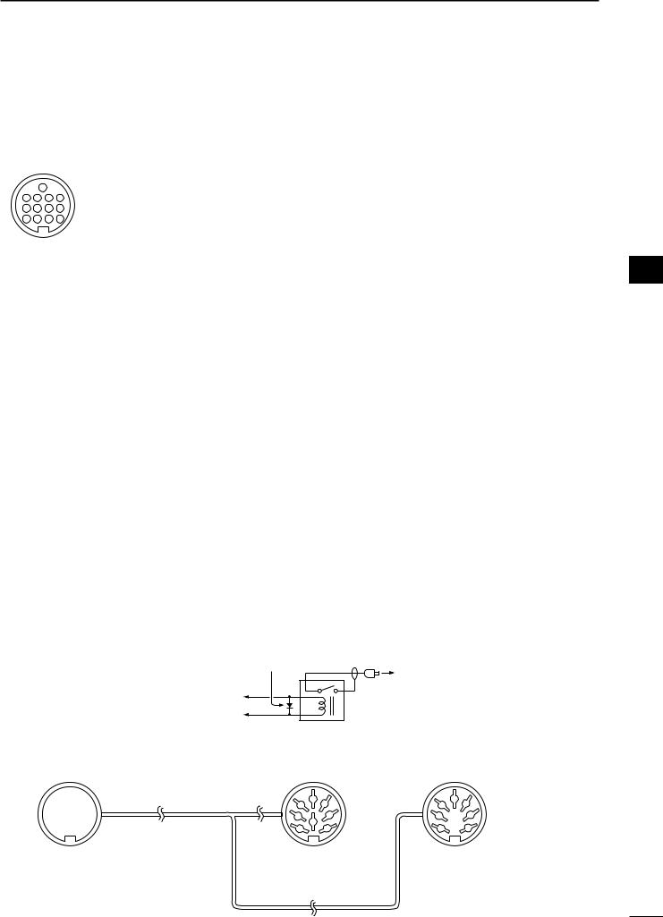
*When the SEND terminal controls an inductive load (such as a relay), a counter-electromotive force can cause the transceiver’s malfunction or damage. To prevent this, we recommend adding a switching diode, such as an “1SS133,” on the load side of the circuit to the counter-electromotive force absorption.
When the diode is added, a switching delay of the relay may occur. Be sure to check its switching action before operation.
[Example] |
ACC |
Switching diode |
To a non-Icom |
|
|||
|
|
||
|
socket |
|
|
|
|
linear amplifier |
|
|
|
|
|
|
eSEND |
|
|
|
i13.8 V |
|
Relay |
|
|
|
• When connecting the ACC conversion cable (OPC-599)
!3 |
Connect to ACC socket |
o !0 1! 2! |
|
t y u i |
|
q w e r |
|
ACC 1 |
4 |
2 |
5 |
ACC 2 |
2 |
5 |
|
|
|
4 |
|||
|
1 |
8 |
3 |
|
1 |
3 |
|
6 |
7 |
|
6 |
7 |
|
|
|
|
||||
q FSKK |
|
t AF |
q 8 V |
t ALC |
||
w GND |
|
y SQL S |
||||
|
w GND |
y NC |
||||
e SEND |
|
u 13.8 V |
||||
|
e SEND |
u 13.8 V |
||||
r MOD |
|
i ALC |
||||
|
r BAND |
|
||||
|
|
|
|
|
||
1
2
3
4
5
6
7
8
9
10
11
12
13
14
15
16
17
18
19
20
21
10
1 PANEL DESCRIPTION
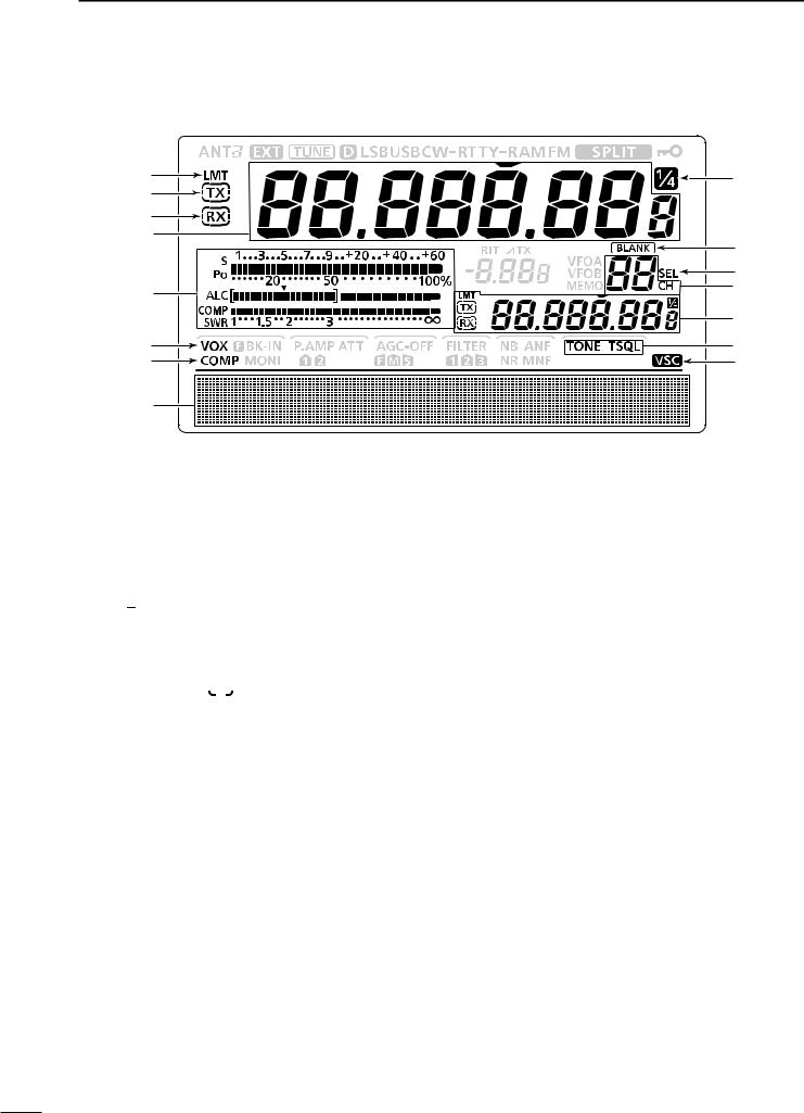
■ LCD display
q |
!5 |
w |
|
e |
|
r |
!4 |
|
|
|
!3 |
t |
!2 |
|
|
|
!1 |
y |
!0 |
u |
o |
i
q POWER DOWN TRANSMISSION ICON (p. 98) Appears when the output power is decreased by the Reduced Power Transmission function.
w TX ICON
Indicates the transmit frequency is displayed.
“
 ” appears while the operating frequency is in an amateur band.
“
 ” appears while the operating frequency is not in an amateur band. However, when the “Band Edge Beep” item is set to “OFF” in the Set mode (p. 85), “
 ” does not appear.
e RX ICON
Indicates the receive frequency is displayed.
r FREQUENCY READOUT
Displays the operating frequency.
•When the quick tuning icon “” is displayed, the frequency changes in kHz quick tuning steps. (p. 27)
•When the quick tuning icon “” is not displayed, the frequency changes in 10 Hz or 1 Hz steps.
When the Split function is ON, displays the receive frequency (VFO A or VFO B). (p. 66)
t MULTI-FUNCTION METER INDICATION
Displays the signal strength while receiving.
Displays the relative output power, ALC and SWR or compression levels while transmitting. (p. 33)
When the Meter Peak Hold function is ON, the peak level of a received signal strength or the output power is displayed for approximately 0.5 seconds. (p. 60)
y VOX ICON (p. 62)
Appears when the VOX function is ON.
u SPEECH COMPRESSOR ICON (p. 64)
Appears when the Speech Compressor function is ON.
i FUNCTION DISPLAY (pp. 13, 14)
Shows the function of the function switches ([F-1] to [F-5]), Set mode items and IF passband width.
o VOICE SQUELCH CONTROL ICON (p. 76) Appears when the VSC (Voice Squelch Control) function is ON.
!0TONE SQUELCH ICONS
(Mode: FM)
“TONE” appears when the Repeater Tone function is ON. (p. 52)
“TSQL” appears when the Tone Squelch function is ON. (p. 50)
!1SPLIT READOUT (pp. 66, 67)
When the Split function is ON, displays the transmit frequency (VFO A or VFO B).
!2MEMORY CHANNEL READOUT (p. 69)
Displays the selected memory channel.
!3SELECT MEMORY CHANNEL ICON (p. 80) Appears when the selected memory channel is set as a select memory channel.
!4BLANK MEMORY ICON (pp. 69, 71)
Appears when the selected memory channel is blank.
!51⁄4 TUNING DIAL SPEED ICON (p. 27)
(Mode: SSB-D/CW/RTTY)
Appears when the tuning dial speed is set so that one rotation is equal to 1⁄4 of the normal rotation.
11
PANEL DESCRIPTION |
1 |
@0 |
!9 |
|
!8 |
!7 |
!6 |
|||
|
|
|
|
|
|
|
|
|
|
|
|
|
|
|
|
|
|
|
|
|
|
|
|
|
|
|
|
|
|
|
|
|
|
|
|
|
|
|
|
|
|
|
|
|
|
|
|
|
|
|
|
|
|
|
|
|
|
|
|
|
|
|
#2
#1
#0
@1
@2
@3 @4 |
@5 |
@6@7@8@9 |
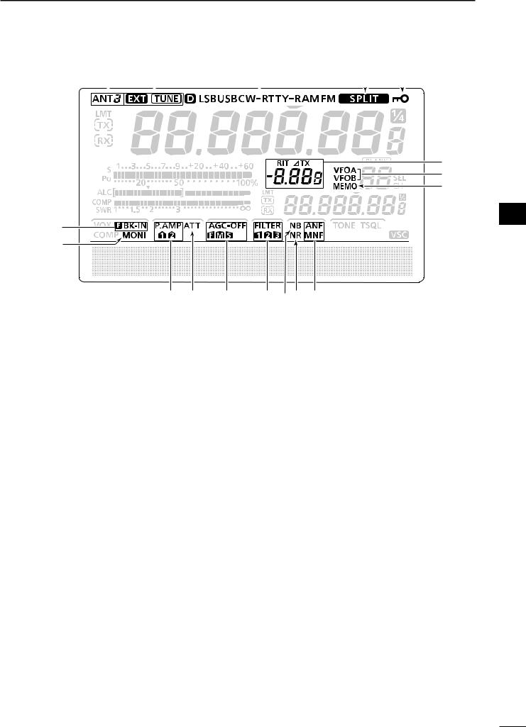
!6DIAL LOCK ICON (p. 61)
Appears when the Dial Lock function is ON.
!7SPLIT ICON (p. 66)
Appears when the Split function is ON.
!8MODE ICONS (p. 31)
Displays the selected operating mode.
•“D” appears when the SSB data, AM data or FM data mode is selected.
!9ANTENNA TUNER ICONS (p. 83)
“ ” appears when the antenna tuner is ON; “
 ” blinks during tuning.
“ ” appears when the optional AH-4 external antenna tuner is connected to the [ANT1] connector, and [ANT1] is selected.
@0ANTENNA ICONS (p. 82)
Displays which antenna connector is selected for
HF/50 MHz.
•“ANT1” appears when the [ANT1] connector is selected.
•“ANT2” appears when the [ANT2] connector is selected.
@1BREAK-IN ICONS (p. 63)
“F BK-IN” appears when the Full Break-in function is ON.
“BK-IN” appears when the Semi Break-in function is ON.
@2MONITOR ICON (p. 65)
Appears when the Monitor function is ON.
@3PREAMP ICONS (p. 55)
Appears when a preamplifier is ON.
• “P. AMP ” for preamp 1; “P. AMP
 ” for preamp 2.
@4ATTENUATOR ICON (p. 55)
Appears when the Attenuator is ON.
@5AGC ICONS (p. 56)
Displays the selected AGC time constant.
•“ ” for fast AGC; “
 ” for mid AGC; “
 ” for slow AGC; “-OFF” for AGC OFF.
@6DSP FILTER ICONS (p. 57)
Displays the selected IF filter.
@7NOISE BLANKER ICON (p. 60) Appears when the Noise Blanker is ON.
@8NOISE REDUCTION ICON (p. 61) Appears when the Noise Reduction is ON.
@9NOTCH ICONS (p. 61)
(Mode: SSB/CW/RTTY/AM)
“MNF” appears when the Manual Notch function is ON.
(Mode: SSB/AM/FM)
“ANF” appears when the Automatic Notch function is ON.
#0MEMORY ICON (p. 24)
Appears when the memory mode is selected.
#1VFO ICONS (p. 24)
Appears when VFO A or VFO B is selected.
#2RIT/∂TX ICONS (pp. 53, 65)
“RIT” appears when the RIT function is ON.
“∂TX” appears when the ∂TX function is ON.
Shows the frequency shift of the RIT or ∂TX function.
1
2
3
4
5
6
7
8
9
10
11
12
13
14
15
16
17
18
19
20
21
12
1 PANEL DESCRIPTION
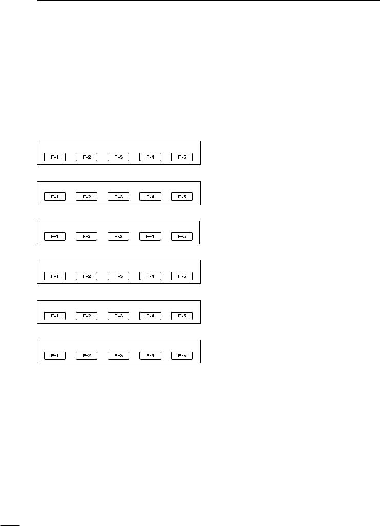
■ Function display
Push [MENU] to toggle between M1 (Menu 1) and M2 (Menu 2).
•The set of functions assigned to the function switches changes, according to the selected menu and operating mode.
Push to select the functions displayed above switches ([F-1] to [F-5]).
• Functions vary, depending on the operating mode.
D M1 (Menu 1)
<MODE> SSB
AGC TBW SCP
<MODE> SSB-D
AGC 1 ⁄ 4 SCP
<MODE> CW
AGC 1 ⁄ 4 KEY SCP
<MODE> RTTY
AGC 1 ⁄ 4 RTTY SCP
<MODE> AM
AGC SCP
<MODE> FM
AGC TON SCP
D Function keys on M1 (Menu 1)
AGC KEY [AGC](F-1) (p. 56)
(Mode: SSB/CW/RTTY/AM/FM)
Push to select the time constant of the AGC circuit.
Hold down for 1 second to display the “AGC” screen.
1⁄4 TUNING FUNCTION KEY [1⁄4](F-3) (p. 27)
(Mode: SSB-D/CW/RTTY)
Push to turn the 1⁄4 Tuning function ON or OFF.
• “ ” is displayed when the 1⁄4 Tuning function is ON.
TRANSMISSION BANDWIDTH KEY [TBW](F-4)
(p. 64)
(Mode: SSB)
Push to display the selected transmission bandwidth.
Hold down for 1 second to select the transmission bandwidth.
•Wide (WIDE), mid (MID) and narrow (NAR) bandwidths are selectable.
MEMORY KEYER MENU KEY [KEY](F-4) (p. 38)
(Mode: CW)
Push to display the “KEY” screen (Memory Keyer) or the “SEND” screen (Keyer Send), depending on the “KEYER 1st Menu” setting in the Set mode (p. 88).
RTTY MENU KEY [RTTY](F-4) (p. 45)
(Mode: RTTY)
Push to display the “RTTY” screen.
TONE SQUELCH KEY [TON](F-4) (p. 50)
(Mode: FM)
Push to select a tone function between subaudible (repeater) tone and tone squelch.
Hold down for 1 second to display the “TON” screen (Tone) of the selected tone function.
BAND SCOPE FUNCTION KEY [SCP](F-5) (p. 54)
(Mode: SSB/CW/RTTY/AM/FM)
Push to display the “SCP” screen (Band Scope).
13
PANEL DESCRIPTION |
1 |
D M2 (Menu 2) |
|
|
D Function keys on M2 (Menu 2) |
|
|
|
|
SCAN KEY [SCAN](F-1) (p. 75) |
|
SCAN MEM |
SWR TCON |
VSC |
||
(Mode: SSB/CW/RTTY/AM/FM) |
||||
|
|
|
||
|
|
|
Push to display the “SCAN” screen. |
MEMORY NAME KEY [MEM](F-2) (p. 73)
(Mode: SSB/CW/RTTY/AM/FM)
Push to display the “MEM” screen (Memory Name Edit).
SWR GRAPH FUNCTION KEY [SWR](F-3) (p. 68)
(Mode: SSB/CW/RTTY/AM/FM)
Push to display the “SWR” screen.
TONE CONTROL SET MODE KEY [TCON](F-4)
(p. 90)
(Mode: SSB/CW/RTTY/AM/FM)
Push to enter the Tone Control Set mode.
VSC FUNCTION KEY [VSC](F-5) (p. 76)
(Mode: SSB/AM/FM)
Push to turn the VSC function (Voice Squelch Control) ON or OFF.
• “ ” appears when the VSC function is ON.
1
2
3
4
5
6
7
8
9
10
11
12
13
14
15
16
17
18
19
20
21
14
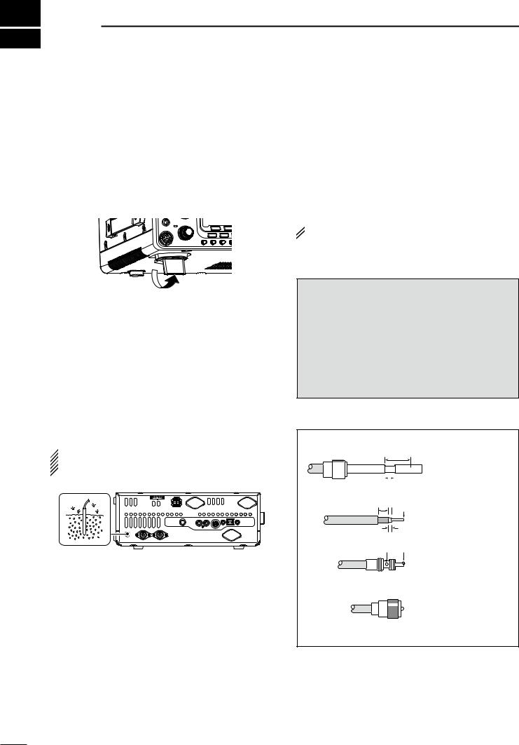
2 INSTALLATION AND CONNECTIONS
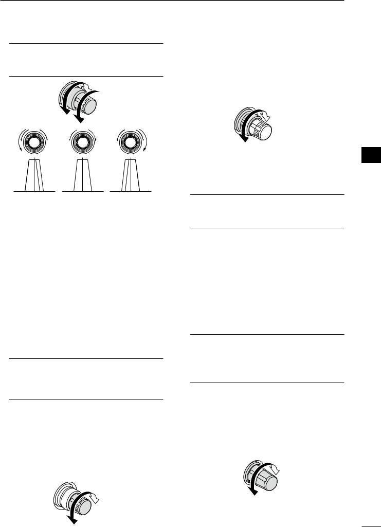
■ Selecting a location
Select a location for the transceiver that allows adequate air circulation, free from extreme heat, cold, or vibrations, and away from TV sets, TV antenna elements, radios and other electromagnetic sources.
The base of the transceiver has adjustable feet for desktop use. Set the feet to one of two angles, to meet your operating preference.
■ Antenna connection
For radio communications, the antenna is of critical importance, along with output power and receiver sensitivity. Select a well-matched 50 ø antenna and coaxial cable feedline. We recommend 1.5:1 or better of Voltage Standing Wave Ratio (VSWR) on your operating bands. The transmission line should be a coaxial cable.
When using a single antenna, use the [ANT1] connector.
 CAUTION: Protect your transceiver from lightning
  by using a lightning arrestor.
■ Grounding
To prevent electrical shock, television interference (TVI), broadcast interference (BCI) and other problems, ground the transceiver using the GROUND terminal on the rear panel.
For best results, connect the heaviest possible gauge wire or strap to a long ground rod. Make the distance between the [GND] terminal and ground as short as possible.
 R WARNING! NEVER connect the [GND] ter-
minal to a gas or electric pipe, since the connection  could cause an explosion or electric shock.
[GND]
Antenna SWR
Each antenna is tuned for a specified frequency range and the SWR usually increases outside the range. When the SWR is higher than approx. 2.0:1, the transceiver automatically reduces the TX power to protect the final transistors. In that case, an antenna tuner is useful to match the transceiver and antenna. Low SWR allows full power for transmitting. The IC-7410 has an SWR meter to continuously monitor the antenna SWR.
PL-259 CONNECTOR INSTALLATION EXAMPLE
q
w
30 mm
|
|
|
|
|
|
|
|
|
|
|
|
|
|
|
|
|
|
|
|
|
|
|
|
Coupling ring |
10 mm |
(tin |
here) |
||||
10 mm
tin
Slide the coupling ring down. Strip the cable jacket and tin the shield.
Strip the cable as shown at left. Tin the center conductor.
1–2 mm
solder solder
e
Slide the connector body on and solder it.
r
Screw the coupling ring onto the connector body.
30 mm (9⁄8 in) 10 mm (3⁄8 in) 1–2 mm (1⁄16 in)
15

INSTALLATION AND CONNECTIONS |
2 |
■ Required connections
D Front panel
ELEC-KEY
(dot)
(com)
(dash)
MICROPHONES (p. 22)
A straight key can be con- |
|
|
|
|
nected. However, “Straight |
|
|
|
|
key” must be selected in |
|
|
|
|
the “Keyer Type” item of the |
HM-36 |
SM-50 |
SM-30 |
|
Keyer Set mode. (p. 43) |
||||
|
(option) |
(option) |
||
|
|
D Rear panel |
DC POWER |
|
|
|
SUPPLY |
|
(p. 19) |
|
PS-126 |
HF/50MHz ANTENNA 1, 2 (p. 15) Connection example:
[ANT 1] for 1.8–18 MHz bands antenna [ANT 2] for 21–28 MHz bands antenna
GROUND (p. 15) |
|
STRAIGHT KEY |
Use the heaviest possible |
|
|
gauge wire or strap and |
|
|
make the connection as |
|
|
short as possible. |
|
|
Grounding prevents elec- |
+ |
|
|
||
trical shocks, TVI |
and |
|
other problems. |
_ |
|
1
2
3
4
5
6
7
8
9
10
11
12
13
14
15
16
17
18
19
20
21
16
2 INSTALLATION AND CONNECTIONS
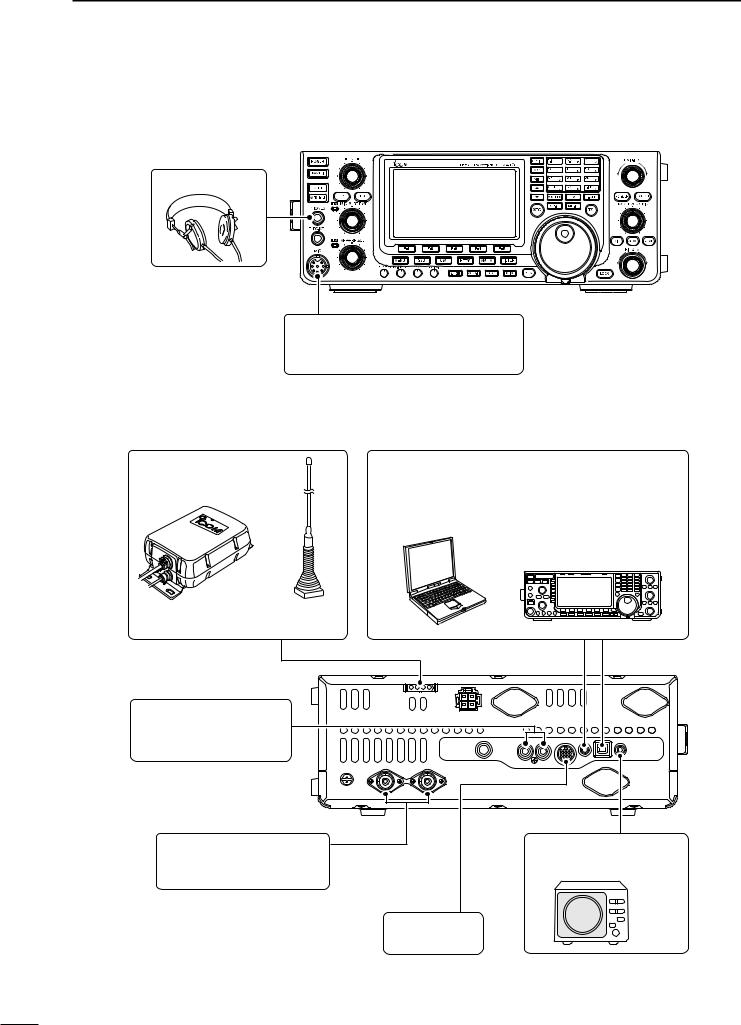
■ Advanced connections
D Front panel
HEADPHONES
MIC
The AFSK modulation signal can also be input to [MIC]. (p. 92)
D Rear panel
REMOTE JACK, USB CONNECTOR (p. 101)
Used for computer control and transceive operation.
The optional CT-17 is required when connecting a
PC to [REMOTE].
|
with |
AH-4 (option) |
AH-2b (option) |
(p. 18) |
or long wire |
[ALC], [SEND] (p. 21) Used for connecting a non-Icom linear amplifier.
[ANT 1], [ANT 2] (p. 82) Connect a linear amplifier, antenna selector, etc.
|
EXTERNAL SPEAKER |
|
(p. 111) |
|
SP-23 |
ACC SOCKET |
(option) |
|
|
(p. 10) |
|
17
INSTALLATION AND CONNECTIONS |
2 |
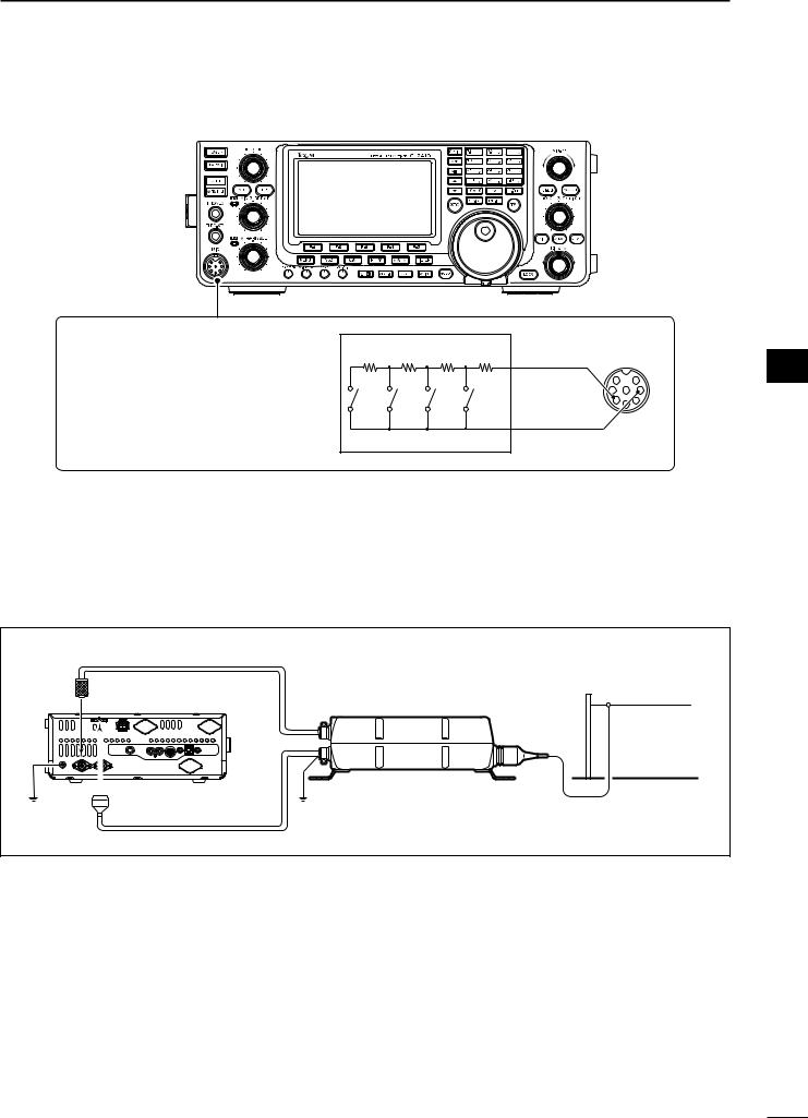
■ External keypad connections
EXTERNAL KEYPAD
Connect an external keypad for keyer memory control.
When using a external keypad, set the “External Keypad” item to “KEYER SEND” in the Set mode. (p. 88)
4.7 kø 2.2 kø |
1.5 kø 1.5 kø |
To pin e |
||
±5% |
±5% |
±5% |
±5% |
|
S4 |
S3 |
S2 |
S1 |
To pin y |
(M4) |
(M3) |
(M2) |
(M1) |
|
EXTERNAL KEYPAD |
|
|
||
1 7
2 8 6
3 |
4 |
5 |
[MIC]
(Front view)
■ External antenna tuner connection
D Connecting the AH-4

 The AH-4 must be connected to [ANT1].
Coaxial cable (from the AH-4)
Long wire or optional AH-2b
[ANT1] |
Transceiver |
AH-4 |
|
[TUNER] |
|
Ground |
Control cable |
Ground |
1
2
3
4
5
6
7
8
9
10
11
12
13
14
15
16
17
18
19
20
21
18
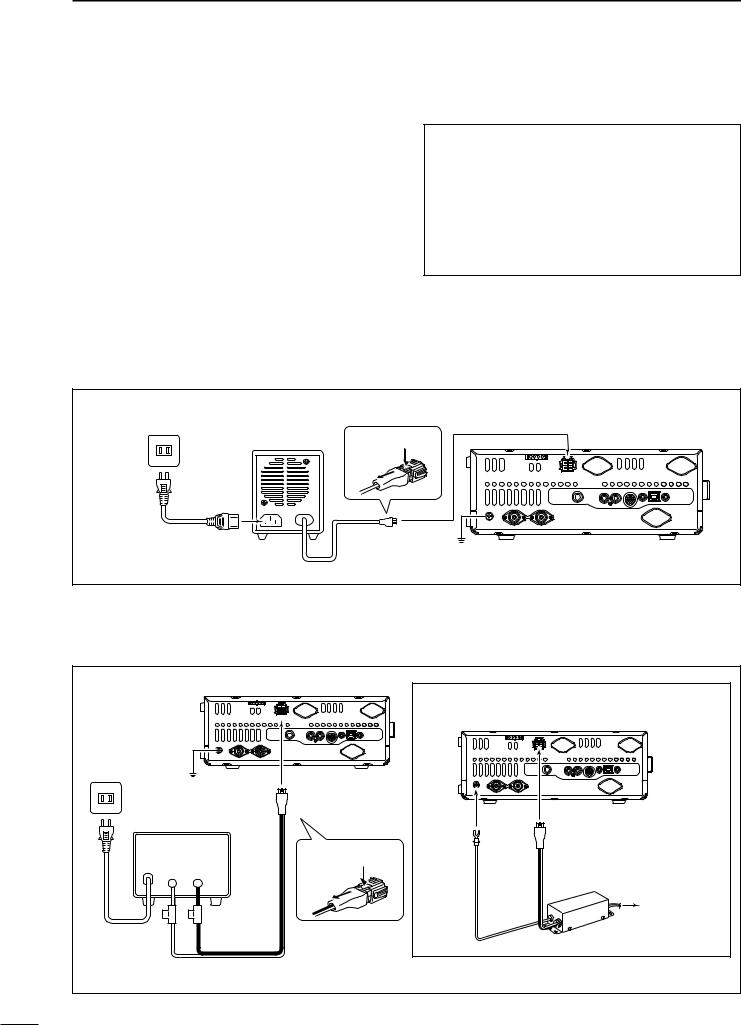
2 INSTALLATION AND CONNECTIONS
■ Power supply connections
When operating the transceiver with AC power, use a power supply with 13.8 V DC output and a capacity of at least 23 Amps.
Refer to the diagrams below.
CAUTION: Before connecting the DC power cable, check the following important items.
Make sure:
•The [POWER] switch is OFF.
•Output voltage of the power source is 12–15 V when you use a non-Icom power supply.
•DC power cable polarity is correct.
Red : Positive + terminal
Black : Negative _ terminal
■ Connecting to a DC power supply
D Connecting to the PS-126 DC POWER SUPPLY
AC outlet |
|
To [DC 13.8V] |
|
PS-126 |
To disconnect |
||
|
|||
|
q |
|
|
|
w |
|
|
AC cable |
Ground |
Transceiver |
|
|
|||
DC power cable |
|
||
D Connecting to a non-Icom DC POWER SUPPLY
|
|
|
Transceiver |
For European versions |
|
|
|
|
|
||
|
|
|
|
|
Transceiver |
AC outlet |
|
|
|
|
|
|
Ground |
To [DC 13.8V] |
|
|
|
|
|
|
|
|
|
A DC power supply |
|
|
|
||
|
13.8 V; |
To disconnect |
To [GND] |
To [DC 13.8V] |
|
|
|
|
|||
|
at least 23 A |
|
|
||
|
q |
|
|
||
|
+ |
_ |
|
|
|
|
|
|
|
||
|
|
|
w |
|
|
|
|
|
|
|
Connect to |
|
|
|
|
|
power supply |
AC cable |
Red |
Black |
|
|
|
|
Supplied DC power cable |
|
|
||
19
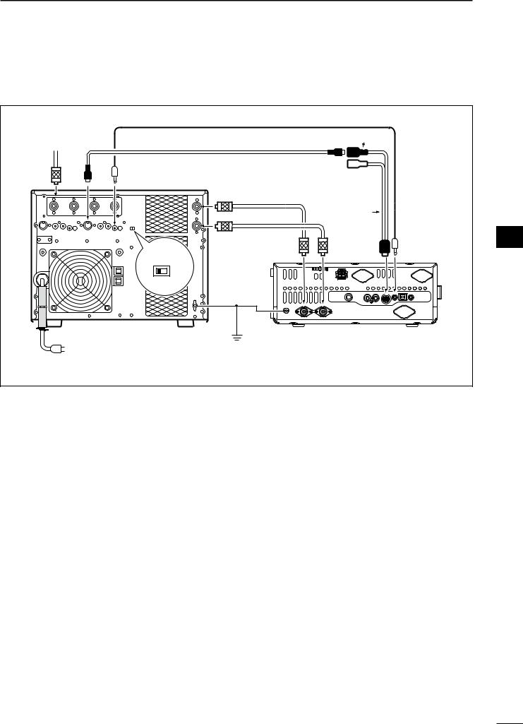
INSTALLATION AND CONNECTIONS |
2 |
■ Linear amplifier connections
D Connecting the IC-PW1/PW1EURO
To an |
|
Remote control cable (supplied with the IC-PW1/PW1EURO) |
|
|
7-pin side |
||
antenna |
[ACC1] |
||
ACC cable (supplied with the IC-PW1/PW1EURO) |
|||
|
|
[ANT] |
[REMOTE] |
EXCITER |
|
1 |
1&2 |
|
Coaxial cable |
|
|
[INPUT1] |
(supplied with the IC-PW1/ |
|
|
PW1EURO) |
|
|
|
Coaxial cable* |
OPC-599 |
|
|
|
|
||
[INPUT2] |
|
[ACC] |
[REMOTE] |
|
[ANT1] |
[ANT2] |
|
[GND] |
|
|
|
IC-PW1/EURO |
[GND] |
|
Transceiver |
||
|
||
AC outlet |
Ground |
|
|
(Non-European versions: 100–120/200–240 V |
* If necessary, purchase sepa- |
|
European version |
: 230 V) |
rately, and connect to [INPUT2]. |
1
2
3
4
5
6
7
8
9
10
11
12
13
14
15
16
17
18
19
20
21
20
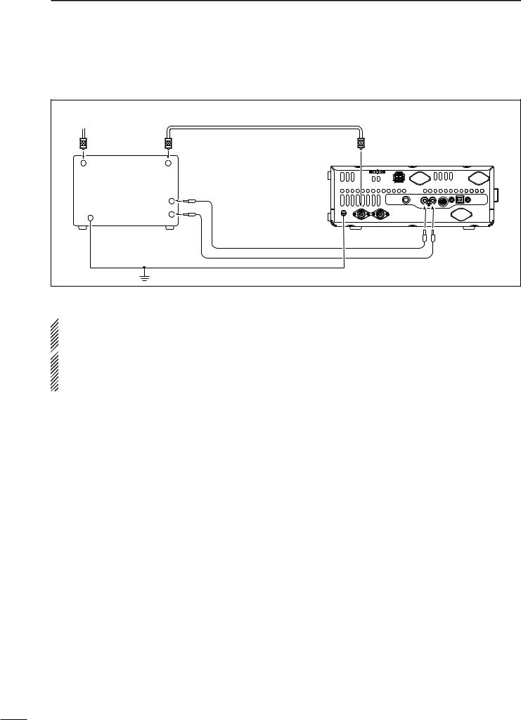
2 INSTALLATION AND CONNECTIONS
■ Linear amplifier connections (Continued)
D Connecting a non-Icom linear amplifier
To an antenna |
|
50 ø coaxial cable |
|
|
|
|
[ANT1] |
Transceiver |
|
RF OUTPUT |
RF INPUT |
|
|
|
GND |
ALC |
|
|
|
SEND |
|
|
|
|
|
|
|
|
|
Non-Icom linear |
[GND] |
[ALC] |
[SEND] |
|
amplifier |
|
|
|
|
|
Ground |
|
|
|
 R WARNING!
• Set the transceiver output power and linear amplifier ALC output level after referring to the linear amplifier in-
struction manual.
 • The ALC input level must be in the range 0 V to –3 V.The transceiver does not accept a positive voltage. Non-
matched ALC and RF power settings could overheat or damage the linear amplifier.
• The IC-7410 SEND terminal (ACC connector pin 3) is rated at 16 V/0.5 A DC. If this value is exceeded, a larger external relay must be used.
21

INSTALLATION AND CONNECTIONS |
2 |
■ Microphone connector information
(Front panel view)
|
i AF output (varies with [AF]) |
q Microphone input |
uGND |
|
(Microphone ground) |
w +8 V DC output |
y GND (PTT ground) |
e Frequency up/down |
t PTT |
|
r Squelch switch |
■ Microphones
D HM-36
q
w
D SM-50 (option)
q |
|
r |
|
w |
e |
|
[MIC] |
FUNCTION |
DESCRIPTION |
|
Pin No. |
|||
|
|
||
|
|
|
|
w |
+8 V DC output |
Max. 10 mA |
|
|
|
|
|
e |
Frequency up |
Ground |
|
|
|
||
Frequency down |
Ground through 470 ˘ |
||
|
|||
|
|
|
|
r |
Squelch open |
“Low” level |
|
|
|
||
Squelch closed |
“High” level |
||
|
|||
|
|
|
 CAUTION: DO NOT short pin 2 to ground as this
can damage the internal 8 V regulator. A DC volt-  age is applied to pin 1 for microphone operation.
  Use caution when using a non-Icom microphone.
q UP/DOWN SWITCHES [UP]/[DN]
Push to change the frequency or memory channel.
• While holding down, the frequency or memory channel number continuously increases or decreases.
• While in the split frequency mode, and holding down
[XFC], push to change the transmit frequency.
• The [UP]/[DN] switch can be used as a key paddle if the “MIC Up/Down Keyer” item is set to “ON” in the Keyer Set mode. In such case, the frequency and memory channel cannot be changed using the [UP]/[DN]
switches. (p. 43)
• You can set the dot-dash polarity of the [UP]/[DN] switch in the “Paddle Polarity” item in the Keyer Set mode. When “Normal” is selected, [UP] sends a dash, and [DN] sends a dot.
w PTT SWITCH
Hold down to transmit; release to receive.
e PTT LOCK SWITCH (available on only the SM-50) Push to toggle between transmit and receive.
r LOW CUT SWITCH (available on only the SM-50) Push to cut out the low frequency components of input voice signals.
1
2
3
4
5
6
7
8
9
10
11
12
13
14
15
16
17
18
19
20
21
22
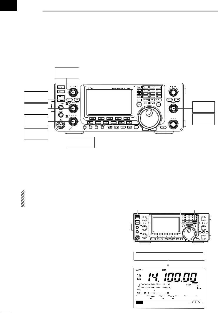
 3 BASIC OPERATION
■ Before first applying power
Before turning ON your transceiver for the first time, make sure all connections required for your system are complete by reviewing them in Section 2 of this manual.
[NR]
: Max. CCW
[RF PWR]
: Max. CW
[MIC]
: 12 o’clock
[AF]
: Max. CCW
[RF/SQL] : 12 o’clock
[KEY SPEED] : 10–12 o’clock
After all connections have been made, set controls and switches as shown in the illustration below.
[NOTCH]
: 12 o’clock


 [CW PITCH] : 12 o’clock
CW : Clockwise
CCW : Counterclockwise
■Turning ON (CPU resetting)
First time to Power ON:
Reset the transceiver using the following procedure.
 Resetting CLEARS all the programmed contents in
the memory channels, and returns all the programmed items in the Set mode to their default set-
tings.
[POWER] [M-CLR] [F-INP ENT]
qMake sure the transceiver’s power is OFF. wWhile holding down both [F-INP ENT] and [M-CLR],
push [POWER] to turn ON the transceiver.
• The CPU is reset.
• The transceiver displays “ALL CLEAR,” then displayes its initial VFO frequency when resetting is complete.
e Change the Set mode settings to suit your operating needs. (p. 85)
Normal Power ON: |
|
Ω ALL CLEAR ≈ |
|
Push [POWER] to turn ON the transceiver. |
|
|
|
|
|
|
|
Power OFF: |
|
|
|
|
|
|
|
Hold down [POWER] for 1 second to turn OFF the |
|
|
|
|
|
|
|
transceiver. |
|
|
|
|
|
|
|
|
|
|
|
M1
AGC TBW SCP
23
 Loading...