


Santamo Mitsubishi Chariot
Table of contents
 Loading...
00
11
12
13
14
15
16
17
21
22
23
25
26
27
31
32
33
34
35
36
37
42
51
52
54
55
00109000812
General ........................
Engine .........................
Engine Lubrication .............
Fuel ...........................
Engine Cooling .................
Intake and Exhaust ............
Engine Electrical ...............
Engine and Emission Control ....
Clutch .........................
Manual Transmission ...........
Automatic Transmission ........
Propeller Shaft .................
Front Axle ......................
Rear Axle ......................
Wheel and Tyre .................
Power Plant Mount ..............
Front Suspension ...............
Rear Suspension ...............
Service Brakes .................
Parking Brakes .................
Steering ........................
Body ...........................
Exterior ........................
Chassis Electrical ..............
WORKSHOP MANUAL
FOREWORD
This Workshop Manual contains procedures for
service mechanics, including removal, disassembly,
inspection, adjustment, reassembly and
installation. Use the following manuals in
combination with this manual as required.
TECHNICAL INFORMATION MANUAL
PYDE9802
WORKSHOP MANUAL
ENGINE GROUP PWEEjjjj
(Looseleaf edition)
ELECTRICAL WIRING PHDE9802
BODY REPAIR MANUAL PBDE9802
PARTS CATALOGUE
SPACE RUNNER B608V509Aj
SPACE WAGON B608W509Aj
All information, illustrations and product
descriptions contained in this manual are current
as at the time of publication. We, however, reserve
the right to make changes at any time without prior
notice or obligation.
“GDI” is the trade mark which Mitsubishi Motors
Corporation holds.
E
Mitsubishi Motors Corporation Aug. 1998
Interior and Supplemental
Restraint System (SRS) ........
.
Heater, Air Conditioner and
Ventilation .....................
.

WARNING!
(1) Improper service or maintenance of any component of the SRS and seat belt with pre-tensioner,
or any SRS-related component, can lead to personal injury or death to service personnel (from
inadvertent firing of the air bag and seat belt with pre-tensioner) or to the driver and passenger
(from rendering the SRS inoperative).
(2) SRS components and seat belt with pre-tensioner should not be subjected to heat, so remove
the SRS-ECU, air bag module (driver’s side and front passenger’s side), clock spring, side
impact sensor, front seat assembly (side air bag module) and seat belt with pre-tensioner before
drying or baking the vehicle after painting.
SRS-ECU, air bag module, clock spring and side impact sensor: 93_C or more
Seat belt with pre-tensioner: 90_C or more
(3) Service or maintenance of any SRS component and seat belt with pre-tensioner or SRS-related
component must be performed only at an authorized MITSUBISHI dealer.
(4) MITSUBISHI dealer personnel must thoroughly review this manual, and especially its GROUP
52B - Supplemental Restraint System (SRS), before beginning any service or maintenance
of any component of the SRS and seat belt with pre-tensioner or any SRS-related component.
NOTE
Section titles with asterisks (*) in the table of contents in each group indicate operations requiring warnings.

21-1
CLUTCH
CONTENTS
21109000190
GENERAL INFORMATION 2..................
SERVICE SPECIFICATIONS 2.................
LUBRICANTS 2..............................
ON-VEHICLE SERVICE 2.....................
Clutch Pedal Inspection and Adjustment 2.......
Bleeding 3.....................................
CLUTCH PEDAL 4...........................
CLUTCH CONTROL 5........................
Clutch Master Cylinder 7.......................

CLUTCH -
General Information/Service Specifications/Lubricants/On-vehicle Service
21-2
GENERAL INFORMATION
21100010093
The clutch is a dry single-disc, diaphragm type;
hydraulic pressure is used for the clutch control.
SERVICE SPECIFICATIONS
21100030150
Items Standard value
Clutch pedal height mm 224 - 227 <L.H. drive vehicles>
211 - 214 <R.H. drive vehicles>
Clutch pedal clevis pin play mm 1-3
Clutch pedal free play mm 6-13
Distance between the clutch pedal and the toeboard
when the clutch is disengaged mm
125 or more
LUBRICANTS
21100040078
Items Specified lubricants Quantity
Clutch fluid Brake fluid DOT3 or DOT4 As required
Push rod assembly Rubber grease
Boot
Release cylinder push rod MITSUBISHI genuine grease
Part No. 0101011
ON-VEHICLE SERVICE
21100090158
CLUTCH PEDAL INSPECTION AND
ADJUSTMENT
1. Turn up the carpet, etc. under the clutch pedal.
2. Measure the clutch pedal height and the clutch pedal
clevis pin play.
Standard value (A):
224 - 227 <L.H. drive vehicles>
211 - 214 <R.H. drive vehicles>
Standard value (B): 1 - 3 mm
Clutch pedal height Clutch pedal clevis
pin play
A
B

CLUTCH -
On-vehicle Service
21-3
3. If the clutch pedal height and the clutch pedal clevis pin
play are outside the standard value, turn the setting nut
to adjust them to the standard value.
Caution
Do not push in the master cylinder push rod at this
time, otherwise the clutch will not operate properly.
4. After completing the adjustments, confirm that the clutch
pedal free play (measured at the face of the pedal pad)
and the distance between the clutch pedal (the face of
the pedal pad) and the toeboard when the clutch is
disengaged are within the standard value ranges.
Standard value (C): 6 - 13 mm
Standard value (D): 125 mm or more
5. If the clutch pedal free play and the distance between
the clutch pedal and the toeboard when the clutch is
disengaged do not agree with the standard values, it
is probably the result of either air in the hydraulic system
or a faulty master cylinder or clutch. Bleed the air, or
disassemble and inspect the master cylinder or clutch.
6. Turn back the carpet, etc.
BLEEDING
21100140143
Specified fluid: Brake fluid DOT 3 or DOT 4
Caution
Use the specified brake fluid. Avoid using a mixture of
the specified fluid and other fluid.
Setting nut
Clutch pedal
12 Nm
Clutch pedal free play
Distance between the clutch pedal and the
toeboard when the clutch is disengaged
C
D
CLUTCH -
Clutch Pedal
21-4
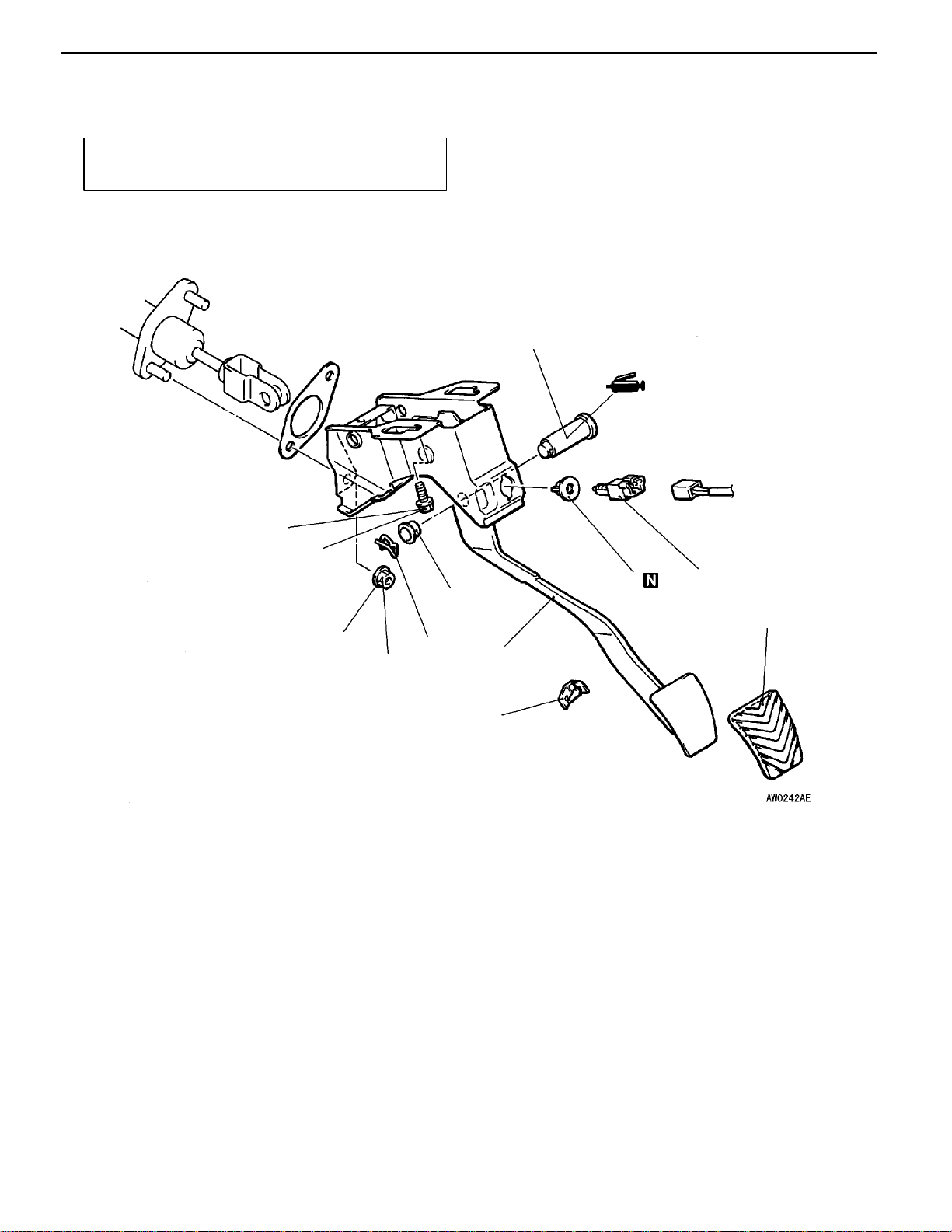
CLUTCH PEDAL
21100160224
REMOVAL AND INSTALLATION
Post-installation Operation
Clutch Pedal Adjustment (Refer to P.21-2)
10
2
8
4
5
6
7
9
3
12 Nm
1
12 Nm
Removal steps
1. Clutch switch
2. Clip
3. Snap pin
4. Bushing
5. Pin assembly
6. Clutch master cylinder mounting nut
7. Master cylinder member mounting bolt
8. Clutch pedal
9. Stopper <R.H. drive vehicles>
10. Pedal pad

CLUTCH -
Clutch Control
21-5
CLUTCH CONTROL
21100190216
REMOVAL AND INSTALLATION
Pre-removal Operation
Clutch Fluid Draining
Post-installation Operation
D Clutch Fluid Supplying
D Clutch Line Bleeding (Refer to P.21-3)
D Clutch Pedal Adjustment (Refer to P.21-2)
<L.H. drive vehicles>
Release
cylinder
push rod
Release
fork
7
6
8
4
8
5
2
1
3
9
19 Nm
Specified grease:
MITSUBISHI genuine
grease Part No. 0101011
15 Nm
7, 8
12 Nm
29 Nm
12 Nm
Clutch master cylinder removal
steps
1. Clevis pin assembly
2. Clutch pipe connection
3. Reservoir hose
4. Clutch master cylinder
Clutch release cylinder removal
steps
5. Clutch pipe connection
6. Clutch release cylinder
Clutch line removal steps
7. Clutch pipe
8. Clutch hose
9. Bracket
10. Clutch hose

CLUTCH -
Clutch Control
21-6
<R.H. drive vehicles>
Release
cylinder
push rod
Release fork
1
2
3
4
5
9
7
12 Nm
8
Specified grease:
MITSUBISHI genuine
grease Part No. 0101011
15 Nm
8
6
19 Nm
12 Nm
7
Clutch master cylinder removal
steps
1. Clevis pin assembly
2. Clutch pipe connection
3. Reservoir hose
4. Clutch master cylinder
Clutch release cylinder removal
steps
5. Clutch pipe connection
6. Clutch release cylinder
Clutch line removal steps
7. Clutch pipe
8. Bracket
9. Clutch hose

CLUTCH -
Clutch Control
21-7
DISASSEMBLY AND REASSEMBLY
21100210172
CLUTCH MASTER CYLINDER
Caution
Do not disassemble piston assembly.
1
2
3
4
5
6
2
8
2
2
3
4
4
1
Grease: Rubber grease
Clutch fluid:
Brake fluid DOT3 or DOT4
Piston repair kit
12 Nm
<L.H. drive vehicles>
<R.H. drive vehicles>
9
6
5
9
7
12 Nm
44 Nm
1
2
3
Disassembly steps
1. Piston stopper ring
2. Piston assembly
"
A
A 3. Push rod assembly
4. Boot
5. Spring pin
6. Nipple
7. Gasket
8. Damper assembly
9. Master cylinder body
CLUTCH -
Clutch Control
21-8
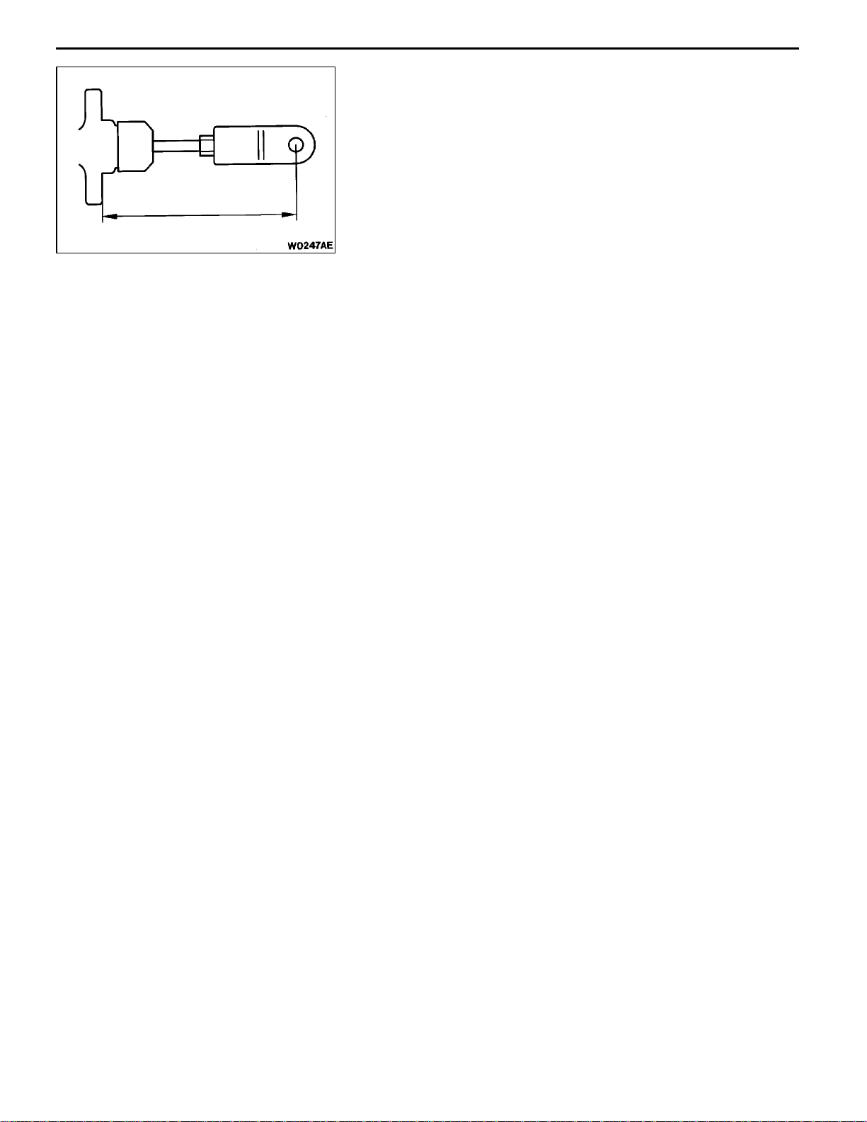
INSTALLATION SERVICE POINT
"
A
A
PUSH ROD ASSEMBLY INSTALLATION
Set the length of the push rod assembly to the shown
dimension to make the adjustment of clutch pedal easier.
<L.H. drive vehicles> 103 mm
<R.H. drive vehicles> 121 mm

22-1
MANUAL
TRANSMISSION
CONTENTS
22109000395
LUBRICANT 2...............................
SPECIAL TOOLS 2..........................
ON-VEHICLE SERVICE 3.....................
Transmission Oil Check 3.......................
Transmission Oil Change 3.....................
Transfer Oil Check 3...........................
Transfer Oil Change
4
..........................
Oil Temperature Sensor Check 4................
TRANSMISSION CONTROL* 5................
TRANSMISSION ASSEMBLY 8................
TRANSFER ASSEMBLY 15..................
WARNING REGARDING SERVICING OF SUPPLEMENTAL RESTRAINT SYSTEM (SRS) EQUIPPED VEHICLES
WARNING!
(1) Improper service or maintenance of any component of the SRS, or any SRS-related component, ca n lead to personal
injury or death to service personnel (from inadvertent firing of the air bag) or to driver and passenger (from rendering
the SRS inoperative).
(2) Service or maintenance of any SRS component or SRS-related component must be performed only at an authorized
MITSUBISHI dealer.
(3) MITSUBISHI dealer personnel must thoroughly review this manual, and especially its GROUP 52B - Supplemental
Restraint System(SRS)before beginning any service ormaintenanceof any componentoftheSRS or anySRS-related
component.
NOTE
The SRS includes the following components: SRS-ECU, SRS warning lamp, air bag module, clock spring, side impact sensors and
interconnecting wiring. Other SRS-related components (that may have to be removed/installed in connection with SRS service or
maintenance) are indicated in the table of contents by an asterisk (*).

MANUAL TRANSMISSION - Lubricant/Special Tools
22-2
LUBRICANT
22100040310
Item Specified lubricant Quantity L
Transmission oil 2WD Hypoid gear oil SAE 75W - 90 or 75W - 85W 2.2
4WD
conforming to API GL-4
2.3
Transfer oil Hypoid gear oil SAE 75W - 90 or 75W - 85W
conforming to API GL-4
0.53
SPECIAL TOOLS
221000600224
Tool Number Name Use
MB990635 or
MB991113
Steering linkage
puller
Ball joint disconnection
GENERAL
SERVICE
TOOL
MZ203827
Engine lifter Supporting the engine assembly during
removal and installation of the transmission
MB991453 Engine hanger
MB991721 Sliding hammer Driving out of the output shaft
MB991 193 Plug To prevent excessive transfer oil loss or system
contamination

MANUAL TRANSMISSION - On-vehicle Service
22-3
ON-VEHICLE SERVICE
22100090308
TRANSMISSION OIL CHECK
1. Remove the oil filler plug.
2. Oil level should be at the lower portion of the filler plug
hole.
3. Check that the transmission oil is not noticeably dirty,
and that it has a suitable viscosity.
4. Tighten the filler plug to the specified torque.
Tightening torque: 32 Nm
TRANSMISSION OIL CHANGE 22100100315
1. Remove the drain plug to drain oil.
2. Tighten the drain plug to the specified torque.
3. Remove the filler plug and fill with specified oil till the
level comes to the lower portion of filler plug hole.
Transmission oil
Specified oil:
Hypoid gear oil SAE 75W - 90 or 75W - 85W
conforming to API GL-4
Quantity: <2WD> 2.2 L
<4WD> 2.3 L
4. Tighten the filler plug to the specified torque.
TRANSFER OIL CHECK 22100110134
1. Remove the oil filler plug.
2. Oil level should be at the lower portion of the filler plug
hole.
3. Check that the transfer oil is not noticeably dirty, and
it has a suitable viscosity.
4. Install the oil filler plug, and then tighten it to the specified
torque.
Tightening torque: 32 Nm
Transmission oil
Filler plug hole
Filler plug
Drain plug
32 Nm
Drain plug
Filler plug
MANUAL TRANSMISSION - On-vehicle Service
22-4
TRANSFER OIL CHANGE 22100120137
1. Remove the oil drain plug to drain oil.
2. Install the oil drain plug, and then tighten it to the specified
torque.
Tightening torque: 32 Nm
3. Remove the oil filler plug, and then fill with specified oil
till the level comes to the lower portion of filler plug hole.
Transfer oil
Specified oil:
Hypoid gear oil SAE 75W - 90 or 75W - 85W
conforming to API GL-4
Quantity: 0.53 L
4. Install the oil filler plug, and then tighten it to the specified
torque.
Specified torque: 32 Nm
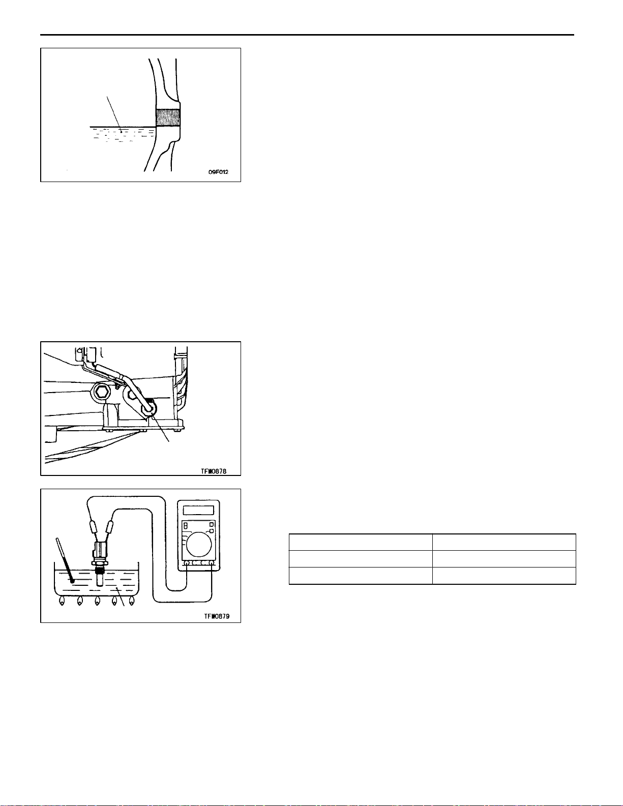
OIL TEMPERATURE SENSOR CHECK 22100670038
1. Remove the oil drain plug, and then drain the transmission
oil.
2. Remove the oil temperature sensor.
3. Measure the resistance between terminals 1 and 2 of
the oil temperature sensor connector.
Standard value:
Oil temperature
_
C Resistance k
W
20 2.31 - 2.59
110 0.145 - 0.149
4. If the resistance is not within the standard value, replace
the oil temperature sensor.
5. Install the oil temperature sensor, and then tighten it to
the specified torque.
Tightening torque: 20 - 25 Nm
6. Install the drain plug and tighten it to the specified torque.
Supply a transmission oil. (Refer to P.22-3.)
Transfer oil
Oil temperature
sensor
Transmission oil

MANUAL TRANSMISSION - Transmission Control
22-5
TRANSMISSION CONTROL
22100380238
REMOVAL AND INSTALLATION
Caution: SRS
Be careful not to subject the SRS-ECU to any shocks during removal and installation of the shift
cable and select cable assembly.
Pre-removal and Post-installation Operation
D Air Cleaner Assembly Removal and Installation
D Battery and Battery Tray Removal and Installation
1
2
3
4
5
6
7
9
10
13
8
11
12 Nm
10
12
14
5Nm
Shift cable and select cable
assembly removal steps
"
B
A
1. Shift knob
"
B
A
2. Spring washer
"
B
A
3. Nut
D
Center console box
(Refer to GROUP 52A.)
4. Insulator
5. Snap pin
6. Select cable connection
(Shift lever side)
7. Clip
8. Shift cable connection
(Shift lever side)
A
A
""
A
A
9. Clip
10. Snap pin
"
A
A
11. Select cable connection
(Transmission side)
"
A
A
12. Shift cable connection
(Transmission side)
13. Shift lever assembly
"
A
A
14. Shift cable and select cable
assembly
Shift lever assembly removal steps
"
B
A
1. Shift knob
"
B
A
2. Spring washer
"
B
A
3. Nut
D
Center console box
(Refer to GROUP 52A.)
4. Insulator
5. Snap pin
6. Select cable connection
(Shift lever side)
7. Clip
8. Shift cable connection
(Shift lever side)
12. Shift lever assembly

MANUAL TRANSMISSION - Transmission Control
22-6
REMOVAL SERVICE POINTS
A
A
"
CLIP REMOVAL
Pry the tabs of the clip with a screwdriver or similar, and
then remove the clip.
INSTALLATION SERVICE POINTS
"
A
A
SHIFT CABLE AND SELECT CABLE ASSEMBLY/
SHIFT CABLE CONNECTION/SELECT CABLE
CONNECTION
1. Set the transmission side shift lever and the passenger
compartment side shift lever to the neutral position.
2. For the transmission side, t he paint marks on the shift
and select cable ends should face the snap pins.
3. Install new clips to the cable bracket at the transmission,
and then install shift cable and select cable to the cable
bracket.
4. Move the passenger compartment side shift lever to all
positions and check that the operation is smooth.
"
B
A
NUT/SPRING WASHER/SHIFT KNOB
INSTALLATION
1. Screw in the nut all the way by hand, turn back half
a turn, and then insert the spring washer.
2. Screw in the shift knob until it touches the spring washer,
and make one more turn. Then turn more to adjust the
shift pattern on the shift knob.
3. If the above steps are impossible, you can turn back
the shift knob by one turn at most after screwing in all
the way to adjust the shift pattern.
Tab s
Shift lever
Neutral position

MANUAL TRANSMISSION - Transmission Control
22-7
SHIFT LEVER ASSEMBLY 22100400101
DISASSEMBLY AND REASSEMBLY
12 Nm
14 Nm
9Nm
9Nm
2
3
4
7
8
10
13
14
15
16
4
12
1
5
6
11
10 Nm
9
Disassembly steps
1. Lever assembly
2. Bolt
3. Select lever
4. Bushing
5. Return spring
6. Collar
7. Bolt
8. Cap
9. Shift lever
10. Shift lever bushing
11. Base bracket
12. Lever mount bracket assembly
13. Insulator
14. Stay
15. Lever mount bracket
16. Base bracket
MANUAL TRANSMISSION - Transmission Assembly
22-8
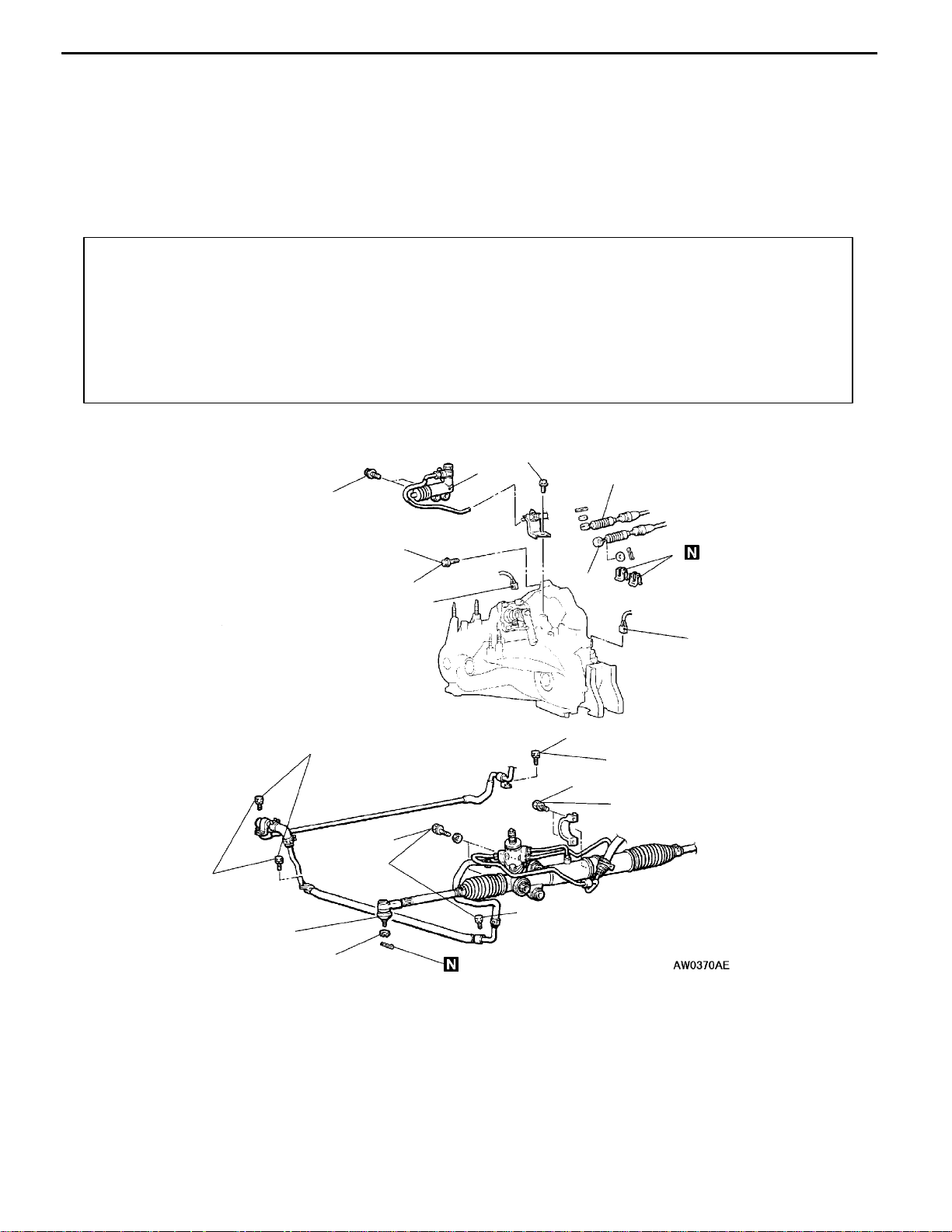
TRANSMISSION ASSEMBLY
22100270290
<2WD>
REMOVAL AND INSTALLATION
Caution
The fasteners indicated by * should be tightened to the specified torque after the engine weight
is applied to the vehicle body.
Pre-removal and Post-installation Operation
D Transmission Oil Draining and Refilling (Refer to
P.22-3.)
D Air Cleaner Assembly Removal and Installation
D Battery and Battery Tray Removal and Installation
D Radiator and Coolant Reservoir Removal and
Installation (Refer to GROUP 14.)
D Starter Removal and Installation (Refer to GROUP
16.)
D Under Cover Removal and Installation
D Front Exhaust Pipe Removal and Installation (Refer
to GROUP 15.)
D Check the Dust Cover for Crack or Damage by
Pushing it with Finger <only after installation>
D Shift Lever Operation Check <only after installation>
D Instruments Operation Check <only after installation>
D Wheel Alignment Check <only after installation>
(Refer to GROUP 33A - On-vehicle Service.)
19 Nm
48 Nm
24 - 33 Nm
12 Nm
19 Nm
12 Nm
69 Nm
9
10
8
5
1
2
7
4
3
6
9
12 Nm
9
9
Removal steps
1. Clip (Refer to P.22-5.)
2. Select cable connection (Refer to
P.22-5.)
3. Shift cable connection (Refer to
P.22-5.)
4. Back-up lamp switch connector
5. Vehicle speed sensor connector
6. Clutch release cylinder connection
A
A
"
7. Tie rod end connection
A
B
"
8. Steering gear and linkage mounting
bolts
9. Oil line mounting bolts
10. Transmission assembly upper cou-
pling bolt

MANUAL TRANSMISSION - Transmission Assembly
22-9
14
44 Nm
13
12
15
19
20
22
9Nm
177 Nm
25
24
39 Nm
17
18
40 Nm
78 Nm
57 Nm*
48 Nm
14
81 Nm*
24
23
26
196 - 255 Nm
98 - 118 Nm
25
22 Nm
49 - 64 Nm*
49 - 64 Nm*
21
177 Nm
78 Nm
11
11. Stabilizer link connection
"
C
A 12. Lower arm connection
13. Wheel speed sensor connection
(Refer to GROUP 35B.)
A
C
""
B
A 14. Drive shaft <Except SPACE
WAGON- R.H.>
A
C
""
B
A 15. Drive shaft and inner shaft
<SPACE WAGON- R.H.>
17. Transmission stay
18. Bell housing cover
19. Front roll stopper connection
20. Rear roll stopper connection
21. Stay
22. Front member assembly
A
E
" 23. Transmission mount bracket
"
A
A 24. Transmission mount stopper
A
F
"DEngine and transmission assembly
supporting
A
G
" 25. Transmission assembly lower part
coupling bolts
A
G
" 26. Transmission assembly

MANUAL TRANSMISSION - Transmission Assembly
22-10
<4WD>
REMOVAL AND INSTALLATION
Caution
The fasteners indicated by * should be tightened to the specified torque after the engine weight
is applied to the vehicle body.
Pre-removal and Post-installation Operation
D Transmission Oil Draining and Refilling (Refer to
P.22-3.)
D Transfer Oil Draining and Refilling (Refer to P.22-3.)
D Air Cleaner Assembly Removal and Installation
D Battery and Battery Tray Removal and Installation
D Radiator and Coolant Reservoir Removal and
Installation (Refer to GROUP 14.)
D Starter Removal and Installation (Refer to GROUP
16.)
D Propeller Shaft Removal and Installation (Refer to
GROUP 25.)
D Under Cover Removal and Installation
D Front Exhaust Pipe Removal and Installation (Refer
to GROUP 15.)
D Check the Dust Cover for Crack or Damage by
Pushing it with Finger <only after installation>
D Shift Lever Operation Check <only after installation>
D Instruments Operation Check <only after installation>
D Wheel Alignment Check <only after installation>
(Refer to GROUP 33A - On-vehicle Service.)
12 Nm
48 Nm
24 - 33 Nm
69 Nm
19 Nm
9
10
8
5
1
2
4
3
6
7
19 Nm
9
9
12 Nm
12 Nm
9
Removal steps
1. Clip (Refer to P.22-5.)
2. Select cable connection (Refer to
P.22-5.)
3. Shift cable connection (Refer to
P.22-5.)
4. Back-up lamp switch connector
5. Vehicle speed sensor connector
6. Clutch release cylinder connection
A
A
"
7. Tie rod end connection
A
B
"
8. Steering gear and linkage mounting
bolts
9. Oil line mounting bolts
10. Transmission assembly upper cou-
pling bolt

MANUAL TRANSMISSION - Transmission Assembly
22-11
26
39 Nm
9Nm
18
16
17
14
21
19
177 Nm
48 Nm
25
13
78 Nm
98 - 118 Nm
20
22 Nm
23
44 Nm
57 Nm*
24
81 Nm*
24
25
14
196 - 255Nm
49 - 64 Nm*
49 - 64 Nm*
78 Nm
22
12
177 Nm
11
11. Stabilizer link connection
"
C
A 12. Lower arm connection
13. Wheel speed sensor connection
(Refer to GROUP 35B.)
A
C
""
B
A 14. Drive shaft
A
D
""
B
A 16. Output shaft
D Transfer assembly removal (Refer to
P.22-15.)
17. Transmission stay
18. Bell housing cover
19. Front roll stopper connection
20. Rear roll stopper connection
21. Stay
22. Front member assembly
A
E
" 23. Transmission mount bracket
"
A
A 24. Transmission mount stopper
A
F
"DEngine and transmission assembly
supporting
A
G
" 25. Transmission assembly lower part
coupling bolts
A
G
" 26. Transmission assembly
MANUAL TRANSMISSION - Transmission Assembly
22-12
REMOVAL SERVICE POINTS
A
A
"
TIE ROD END DISCONNECTION
Caution
1. Use thespecial tool to loosen the tie rod end mounting
nut. Only loosen the nut; do not remove it from the
ball joint.
2. Support the special tool with a cord, etc. not to let
it come off.
A
B
"
STEERING GEAR AND LINKAGE MOUNTING
BOLT REMOVAL
Remove the steering gear and linkage mounting bolts, and
then support the steering gear box to the vehicle body with
a wire.
A
C
"
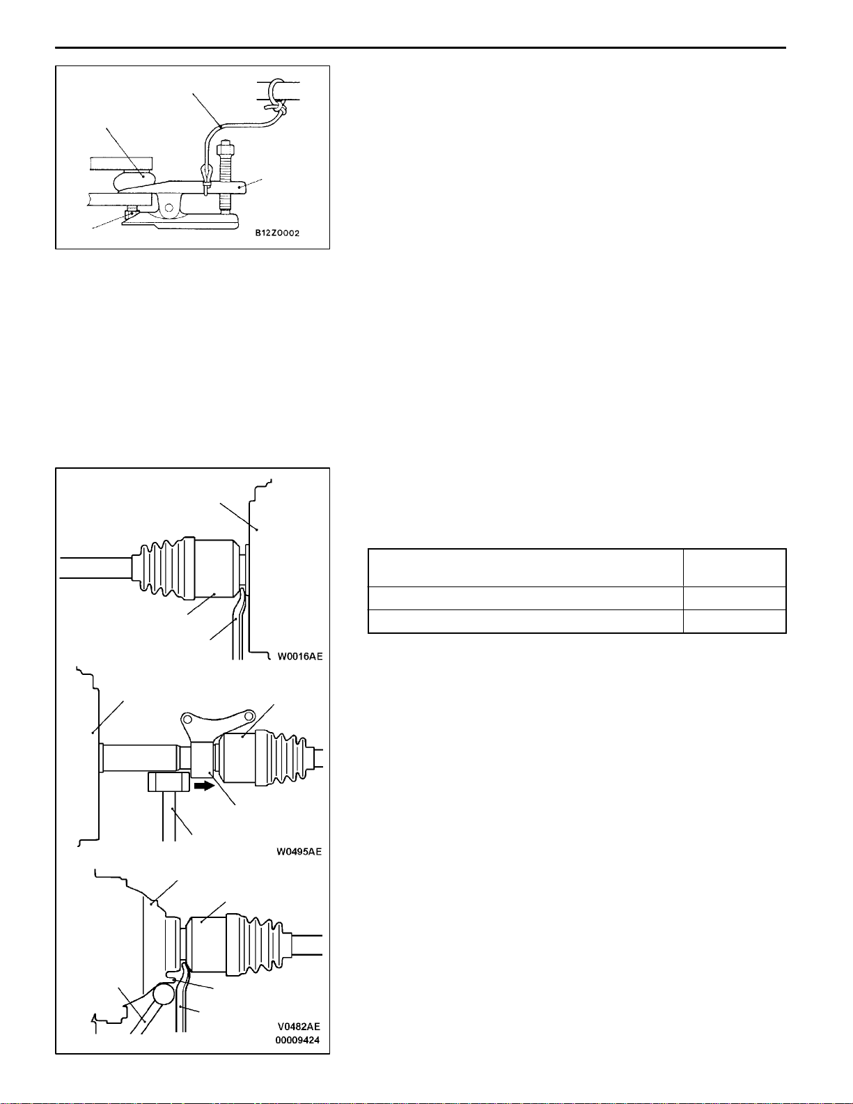
DRIVE SHAFT/DRIVE SHAFT AND INNER SHAFT
ASSEMBLY REMOVAL
Remove the drive shaft or the drive shaft and inner shaft
assembly from the transmission by the following procedure:
2WD (except SPACE WAGON - M/T- R.H.),
4WD (L.H.)
Fig. 1
2WD (SPACE WAGON- M/T- R.H.) Fig. 2
4WD (R.H.) Fig. 3
<Fig. 1>
Insert a pry bar between the drive shaft a n d the
transmission case, and then pry off the drive shaft.
<Fig. 2>
Tap the center bearing bracket with a hammer to remove
the drive shaft.
<Fig. 3>
Place a hammer on the projection at th e transfer and
insert a pry bar between the drive shaft and the transfer,
and then pry off the drive shaft.
Caution
1. Above-mentioned procedure must be observed.
Pulling the B.J. assembly to remove the drive shaft
or drive shaft and inner shaft assembly will damage
the T.J. assembly.
2. Take care that the transmission oil seal will not be
damaged by the drive shaft spline.
Cord
Ball joint
MB990635 or
MB991113
Nut
Transmission
Drive shaft
Transfer
Drive shaft
Center bearing bracket
Transmission
Drive shaft
Prybar
Hammer
Prybar
Hammer
Projection
Fig. 1
Fig. 2
Fig. 3

MANUAL TRANSMISSION - Transmission Assembly
22-13
A
D
"
OUTPUT SHAFT REMOVAL
1. Use the special tool to withdraw the output shaft.
Caution
Be careful not to damage the oil seal of the
transmission by the spline of the output shaft.
2. Use a shop towel to cover the transmission case not
to let foreign material ge t into it.
A
E
"
TRANSMISSION MOUNT BRACKET REMOVAL
Carefully lower the transmission assembly with a garage jack,
and remove the transmission mount bracket.
A
F
"
ENGINE AND TRANSMISSION ASSEMBLY
SUPPORTING
Set the special tool to the vehicle to support the engine and
transmission assembly.
A
G
"
TRANSMISSION ASSEMBLY LOWER PART
COUPLING BOLTS/TRANSMISSION ASSEMBLY
REMOVAL
1. Support the transmission assembly with a transmission
jack.
2. Remove the transmission assembly lower part coupling
bolts, and lower the transmission assembly to remove.
INSTALLATION SERVICE POINTS
"
A
A
TRANSMISSION MOUNT STOPPER INSTALLATION
Install the transmission mount stopper so that the arrow points
as shown in the illustration.
NOTE
Disregard F and R stamped as a shared part.
MB991721
Output shaft
MZ203827
MB991453
Transmission
mount
stopper
Transmis-
sion
mount
bracket
Engine side

MANUAL TRANSMISSION - Transmission Assembly
22-14
"
B
A
OUTPUT SHAFT/DRIVE SHAFT INSTALLATION
Caution
Be careful not to damage the oil seal of the transmission
or transfer by the spline of the drive shaft or the output
shaft.
"
C
A
LOWER ARM INSTALLATION
1. Install the lower arm assembly to the knuckle.
Caution
The lower arm should not protrude 4 mm or more
from the knuckle end (A shown), otherwise grease
may pour out from the dust cover.
2. If grease has poured out due to the excessive arm
protrusion, the dust cover must be replaced (Refer to
GROUP 33A - Lower Arm).
3. There should be not clearance between the knuckle and
the dust cover.
Lower arm
assembly
Knuckle
A
MANUAL TRANSMISSION - Transfer Assembly
22-15
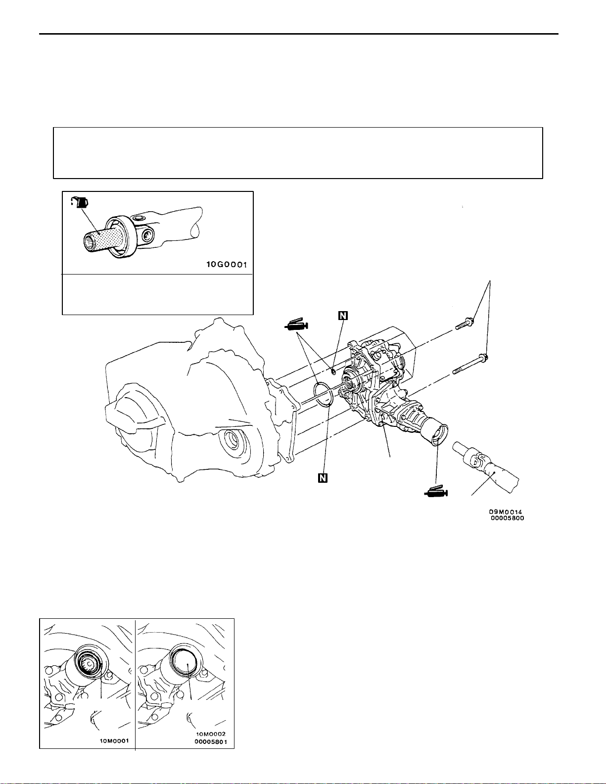
TRANSFER ASSEMBLY
REMOVAL AND INSTALLATION
Caution
The fasteners indicated by * should be tightened to the specified torque after the engine weight
is applied to the vehicle body.
Pre-removal and Post-installation Operation
D Transmission Oil Draining and Refilling (Refer to
P.22-3.)
D Transfer Oil Draining and Refilling (Refer to P.22-4.)
D Front Exhaust Pipe Removal and Installation (Refer
to GROUP 15.)
1
2
69 Nm
Gear oil:
Hypoid gear oil SAE 75W - 85W or
75W - 90 conforming to API GL-4
Removal steps
D
Drive shaft connection (Refer to
P.22-11.)
D
Output shaft (Refer to P.22-11.)
1. Front propeller shaft (Refer to
GROUP 25.)
A
A
"
2. Transfer assembly
REMOVAL SERVICE POINT
A
A
"
TRANSFER ASSEMBLY REMOVAL
Caution
1. Be careful not to damage the transfer oil seal lip.
2. Use the special tool to plug the transfer case opening
to to prevent excessive oil loss or system
contamination.
Oil seal lip
MB991113

NOTES

23-1
AUTOMATIC
TRANSMISSION
CONTENTS
23109000576
SERVICE SPECIFICATIONS 2.................
LUBRICANT 2...............................
SPECIAL TOOLS 2..........................
TROUBLESHOOTING 4.......................
ON-VEHICLE SERVICE 44...................
Essential Service 44............................
A/T Control Component Location 50.............
A/T Control Component Check 51...............
Torque Converter Stall Test 53..................
Hydraulic Pressure Test 55.....................
Hydraulic Circuit 60............................
Line Pressure Adjustment 61....................
Selector Lever Operation Check 61..............
TRANSMISSION CONTROL* 63..............
SHIFT LOCK AND KEY INTERLOCK
MECHANISMS 66...........................
TRANSMISSION ASSEMBLY 68..............
WARNING REGARDING SERVICING OF SUPPLEMENTAL RESTRAINT SYSTEM (SRS) EQUIPPED VEHICLES
WARNING!
(1) Improper service or maintenance of any component of the SRS, or any SRS-related component, ca n lead to personal
injury or death to service personnel (from inadvertent firing of the air bag) or to driver and passenger (from rendering
the SRS inoperative).
(2) Service or maintenance of any SRS component or SRS-related component must be performed only at an authorized
MITSUBISHI dealer.
(3) MITSUBISHI dealer personnel must thoroughly review this manual, and especially its GROUP 52B - Supplemental
Restraint System(SRS)before beginning any service ormaintenanceof any componentoftheSRS or anySRS-related
component.
NOTE
The SRS includes the following components: SRS-ECU, SRS warning lamp, air bag module, clock spring, side impact sensors and
interconnecting wiring. Other SRS-related components (that may have to be removed/installed in connection with SRS service or
maintenance) are indicated in the table of contents by an asterisk (*).

AUTOMATIC TRANSMISSION -
Service Specifications/Lubricant/Special Tools
23-2
SERVICE SPECIFICATIONS
23100030284
Items Standard value
Oil temperature sensor kW at 0_C 16.5 - 20.5
at 100_C 0.57 - 0.69
Resistance of damper clutch control solenoid valve coil (at 20_C) W 2.7 - 3.4
Resistance of Low-Reverse solenoid valve coil (at 20_C) W 2.7 - 3.4
Resistance of second solenoid valve coil (at 20_C) W 2.7 - 3.4
Resistance of underdrive solenoid valve coil (at 20_C) W 2.7 - 3.4
Resistance of overdrive solenoid valve coil (at 20_C) W 2.7 - 3.4
Stall speed r/min 4G93 2,200 - 2,700
4G64 2,300 - 2,800
LUBRICANT
23100040270
Items Specified lubricant Quantity L
Transmission fluid DIA QUEEN ATF SPII,ATF SPIIMor
equivalent
7.8
SPECIAL TOOLS
23100060351
Tool Number Name Use
MB991502 MUT-II sub
assembly
Checking of the diagnosis code
MD998330
(including
MD998331)
Oil pressure gauge
(2,942 kPa)
Measurement of oil pressure
MD998332 Adapter
MD998900 Adapter

AUTOMATIC TRANSMISSION -
Special Tools
23-3
Tool Number Name Use
MB990635 or
MB991113
Steering linkage
puller
Ball joint disconnection
MB991610 Oil filter wrench Removal and installation of automatic trans-
mission oil filter
GENERAL
SERVICE
TOOL
MZ203827
Engine lifter Supporting the engine assembly during
removal and installation of the transmission
MB991453 Engine hanger
assembly
Supporting the engine assembly during
removal and installation of the transmission
AUTOMATIC TRANSMISSION -
Troubleshooting
23-4
TROUBLESHOOTING
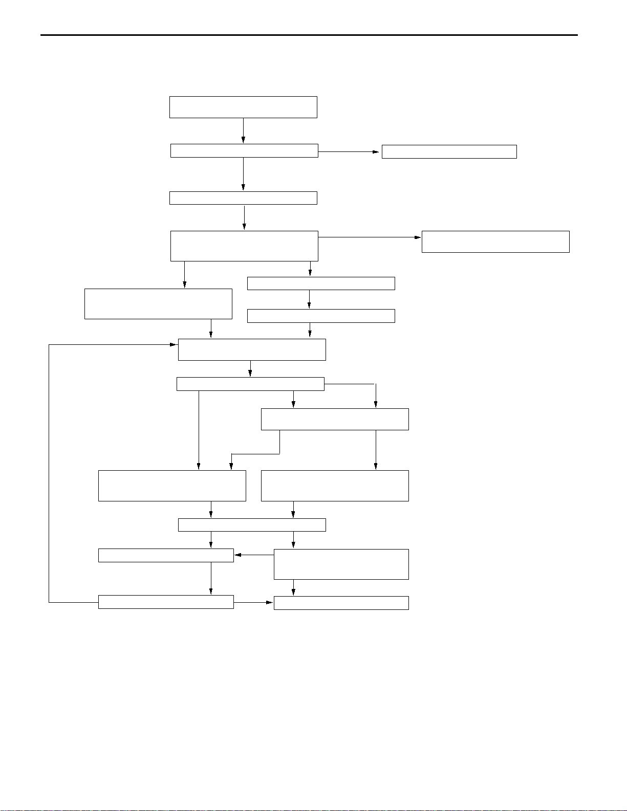
23100760657
STANDARD FLOW OF DIAGNOSIS TROUBLESHOOTING
Gathering information from custom-
er.
Check trouble symptoms.
Read the diagnosis code (GROUP 00
- How to Use Troubleshooting/In-
spection Service Points.)
Communication with
MUT-II not possible
Inspection Chart For Trouble
Symptoms (Refer to P.23-24.)
Diagnosis code
displayed
Erase the diagnosis code (GROUP
00 - How to Use Troubleshooting/In-
spection Service Points.)
No diagnosis code displayed
Carry out the essential service
(Refer to P.23-44.)
Road test (Refer to P.23-6.)
Abnormality exists (no diagnosis code)
No abnormality
Recheck diagnosis codes which
were read before the road test.
Abnormality exists
(diagnosis code
present)
Diagnosis
code displayed
No diagnosis
code displayed
To INSPECTION CHART FOR
DIAGNOSIS CODES
(Refer to P.23-12.)
To INSPECTION CHART FOR
TROUBLE SYMPTOMS
(Refer to P.23-24.)
Search for cause.
Found Not found
Repair
Confirmation test (road test)
NG
NG
INTERMITTENT MALFUNCTION
(GROUP 00 - Points to Note for
Intermittent Malfunctions.)
OK
Completed
OK
Check ATF.
Replace ATF.
Check trouble symptoms.
Replace the A/T-ECU.
NG
OK
NG
Loading...