


Engine
Mechanical
System
ENGINE (KJ2.9 TCI DOHC DIESEL-COMMON RAIL SYSTEM) |
........EM- 2 |
LUBIRICATION SYSTEM ................................................................... |
EM-52 |
COOLING SYSTEM ............................................................................ |
EM-59 |
INTAKE AND EXHAUST SYSTEM..................................................... |
EM-65 |
ENGINE (KJ2.9 TCI DOHC DIESEL-COMMON RAIL SYSTEM)
SPECIAL SERVICE TOOLS ............................................................... |
EMa-2 |
SYMPTOM-RELATED DIAGNOSTIC PROCEDURE ......................... |
EMa-4 |
SPECIFICATION ................................................................................. |
EMa-7 |
ON-VEHICLE SERVICE PROCEDURES............................................ |
EMa-8 |
REMOVAL AND REPLACEMENT PROCEDURES.......................... |
EMa-16 |
DISASSEMBLY, INSPECTION AND REASSEMBLY PROCEDURE.......... |
EMa-24 |

EM-2 |
ENGINE (KJ2.9 TCI DOHC DIESEL-COMMON RAIL SYSTEM) |
|
|
SPECIAL SERVICE TOOLS
Engine
Special service tools
0K130 990 007
Engine stand
Used to disassemble and assemble engine.
0K410 101 004
Hanger, engine stand
Used to disassemble and assemble engine.
0K993 120 004
Pivot, valve spring lifter
Used to remove and install valve.
0K710 120 004
Installer, valve seal
Used to install valve seal.
0K130 160 010
Centering tool, clutch disc
Used to install clutch disc and clutch cover.
0K552 111 001
Holder, camshaft pulley
Used to install camshaft pulley.
0K552 131 002
Adapter, compression gauge
Used to measure compression pressure.
0K993 120 001
Arm, valve spring lifter
Used to remove and install valve.

|
|
|
|
SPECIAL SERVICE TOOLS |
EM-3 |
0K993 120 006
Remover, valve seal
Used to remove valve seal.
0K590 111 001
Ring gear brake set
Used to prevent engine rotation.
0K130 111 004
Holder, coupling flange
Used to remove camshaft gear.
EM-4 |
ENGINE (KJ2.9 TCI DOHC DIESEL-COMMON RAIL SYSTEM) |
|
|
SYMPTOM-RELATED DIAGNOSTIC PROCEDURE
Engine
Diagnostic chart
Problem |
|
Possible Cause |
Action to be taken |
|
|
|
|
Insufficient power |
Insufficient compression caused by: |
|
|
smoke generation |
1. |
Contaminated air cleaner element |
|
|
2. |
Loose hose connection between compressor |
|
|
|
and intercooler |
|
|
3. |
Leakage from intake manifold |
|
|
4. |
Leakage from exhaust manifold |
|
|
5. |
Leakage from turbocharger mounting flange |
|
|
6. |
Interference between turbocharger compressor |
|
|
|
turbine and case |
|
|
7. |
Blocked duct between air cleaner and turbocharger |
|
|
|
compressor |
|
|
8. |
Blocked duct between compressor and intake manifold |
|
|
9. |
Interference between intake and exhaust manifolds |
|
|
10. |
Leakage from valve seat |
|
|
11. |
Seized valve stem |
|
|
12. |
Weak or broken valve spring |
|
|
13. |
Failed cylinder head gasket |
|
|
14. |
Cracked or distorted cylinder head |
|
|
15. |
Sticking, damaged, or worn piston ring |
|
|
16. |
Cracked or worn piston |
|
|
Malfunction of fuel system |
|
|
|
Slipping clutch |
|
|
|
Wrong tire size |
|
|
|
Restricted exhaust system |
|
|
|
system |
|
|
|
|
|
|
Excessive oil |
Abnormal engine oil viscosity |
Replace |
|
consumption |
Leakage from turbocharger compressor |
Repair |
|
|
(adhesion of oil to housing or wheel) |
|
|
|
Leakage turbocharger turbine |
Repair |
|
|
Worn or sticking piston ring or groove |
Replace |
|
|
Worn piston or cylinder |
Repair or replace |
|
|
Bad valve seal |
Replace |
|
|
Worn valve stem or guide |
Replace |
|
|
|
|
|
Engine cranks |
Malfunction of fuel system |
|
|
normally, but does |
Malfunction of electrical system |
|
|
not start |
|
|
|
|
Restricted exhaust system |
|
|
|
Timing belt and/or related parts |
Replace |
|
|
Low compression |
|
|
|
Camshaft worn |
|
|
|
|
|
|
Blue smoke out of |
Usually caused by oil burning in the combustion chamber from: |
Replace |
|
exhaust |
worn rings, worn valve guides, worn valve seals or failed |
|
|
|
cylinder head gasket |
|
|
|
Contaminated air cleaner element |
|
|
|
Loose hose connection between compressor and intercooler |
Tighten |
|
|
Leakage from intake manifold |
Repair |
|
|
Blocked oil filter |
Replace |
|
|
Blocked duct between air cleaner and turbocharger compressor |
Repair |
|
|
Leakage from turbocharger compressor |
Repair |
|
|
|
|
|
SYMPTOM-RELATED DIAGNOSTIC PROCEDURE |
EM-5 |
|
|
|
|
|
|
|
Problem |
Possible Cause |
Action to be taken |
|
|
|
White smoke out of |
Usually caused by water vapor, which is a normal by product |
None required |
exhaust |
of combustion on cold days. |
|
|
Excessive white smoke with engine warmed up could be |
Repair or replace |
|
caused by a failed cylinder head or intake gasket, could also |
|
|
be cracked block, cylinder head or intake manifold. |
|
|
|
|
Black smoke out of |
Malfunction of fuel system |
|
exhaust |
Malfunction of emission system |
|
|
|
|
Abnormal combustion |
Sticking or burned valve |
Replace |
|
Weak or broken valve spring |
Replace |
|
Carbon accumulation in combustion chamber |
Eliminate the carbon |
|
|
|
Poor idling |
Malfunction of fuel system |
|
|
Malfunction of emission system |
|
|
Uneven cylinder compression |
Repair |
|
Poor valve to valve seat contact |
Repair or replace |
|
Broken valve spring |
Repair |
|
Failed cylinder head gasket |
Replace |
|
|
|
Turbocharger noise |
Contaminated air cleaner element |
Replace |
|
Foreign material in intake duct or compressor housing |
Clean |
|
Foreign material between intake manifold and compressor |
Clean |
|
Foreign material in engine exhaust system |
Clean |
|
Carbon deposit on turbine housing |
Clean |
|
Interference between turbocharger rotating parts |
Repair or replace |
|
Loose connecting parts of intake and exhaust system |
Tighten |
|
|
|
Engine knocks when |
Loose or worn accessory drive belt/tensioner |
Replace if necessary |
hot and at idle |
Improper oil viscosity |
Install proper oil viscosity for |
|
|
expected temperature |
|
Excessive piston pin clearance |
Install new piston pin and/or |
|
|
connecting rod |
|
Connecting rod alignment |
Check and replace |
|
Insufficient piston to bore clearance |
Hone and fit new pistons |
|
Faulty timing belt tensioner or guide |
Replace |
|
Loose damper pulley |
Tighten or replace |
Slight noise at idle, |
Valve spring clicking on cap, off square or broken |
Repair or replace |
becomes louder as engine |
Excessive stem to guide clearance |
Repair |
speed is increased |
Excessive valve seat runout |
Repair |
|
Holed exhaust pipe |
Replace |
|
|
|
Engine knoks when cold |
Excessive piston to wall clearance |
Replace |
|
Loose or broken damper pulley |
Tighten or replace |
|
|
|
Knock increase with |
Excessive piston to bore clearance |
Replace piston |
torque |
Bent connecting rod |
Replace |
|
|
|
Engine has heavy knock |
Broken damper pulley |
Replace |
when hot and torque is |
Accessory belts too tight or damaged |
Adjust or replace belt |
applied |
Belt tensioner damaged |
Replace |
|
Flywheel cracked or loose clutch plate |
Replace flywheel or clutch plate |
|
Excessive main bearing clearance |
Repair |
|
Excessive rod bearing clearance |
Repair |
|
|
|
EM-6 |
ENGINE (KJ2.9 TCI DOHC DIESEL-COMMON RAIL SYSTEM) |
|
|
|
|
|
|
|
Problem |
Possible Cause |
Action to be taken |
|
|
|
Engine has light knock |
Improper timing |
Check timing |
when hot and under |
Piston pin and/or connecting rod |
Replace |
light lood conditions |
Poor quality fuel |
Replace |
|
Exhaust leak at manifold |
Tighten or replace |
|
Excessive rod bearing clearance |
Repair |
|
|
|
Engine knocks on initial |
Improper oil viscosity |
Install proper oil viscosity |
start up and knock lasts |
|
for expected temperature |
only a few seconds |
|
|
|
|
|
Interference of |
Damaged compressor blades due to external cause |
Repair or replace |
turbocharger, poor |
Interference of turbine and compressor blades with housing |
Repair or replace |
rotation |
Excessive deposit on compressor housing or wheel |
Clean or repair |
|
Excessive carbon deposit on the back of turbine blade |
Clean or repair |
|
Burn out of center housing |
Replace |
|
|
|
Leakage from |
Excessive initial oil applying |
Burn it normally |
turbocharger turbine shaft |
Blocked crankcase breather |
Repair |
|
Obstacle in turbocharger oil drain line |
Clean and repair |
|
Burn out of center housing |
Clean and replace |
|
Wear on turbocharger bearing, bearing bore or shaft journal |
Repair or replace |
|
Excessive crankcase oil |
Correct oil amount |
|
|
|
Leakage from |
Contaminated air cleaner element |
Replace |
turbocharger compressor |
Blocked duct between compressor and air cleaner |
Repair |
|
Loose compressor and intake system connecting duct |
Tighten |
|
Leakage from intake manifold |
Repair |
|
Obstacle in turbocharger oil drain line |
Repair or replace |
|
Blocked blowby passage in crankcase |
Repair |
|
Worn or damaged compressor blades |
Clean or replace |
|
Wear or turbocharger bearing bore, bearing or shaft journal |
Replace |
|
|
|
Wear on turbocharger |
Contaminated oil |
Replace |
bearing, bore or shaft |
Insufficient oil supply |
Check |
journal |
Obstacle in turbocharger oil supply line |
Check and repair |
|
Plugged oil filter |
Replace |
|
Poor oil pump operation |
Check and repair |
|
|
|
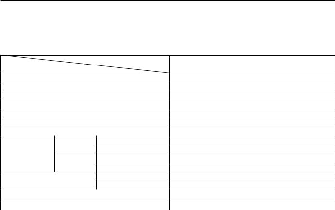
SPECIFICATION |
|
|
EM-7 |
SPECIFICATION |
|
|
|
Engine |
|
|
|
Specification |
|
|
|
|
|
Engine model |
KJ 2.9TCI DOHC-COMMON RAIL SYSTEM |
Item |
|
|
|
|
|
|
|
Type |
|
|
Diesel, 4-Cycles |
Number of cylinders |
|
|
4-Cylinder in-line |
Combustion chamber |
|
Re-entrant |
|
Displacement |
|
cu. in (cc) |
177 (2902) |
Bore and stroke |
|
in (mm) |
3.82 X 3.85 (97.1 X 98) |
Compression ratio |
|
|
19.3 |
Compression pressure |
psi (kPa, kg/cm2)-rpm |
426.6 (2943, 30) - 200 |
|
Valve timing |
Intake |
Open |
BTDC 26° |
|
|
Closed |
ABDC 50° |
|
Exhaust |
Open |
BBDC 50° |
|
|
Closed |
ATDC 29° |
Valve clearance(cold engine) |
Intake |
0 : Maintenance-free |
|
|
in (mm) |
Exhaust |
0 : Maintenance-free |
Idle speed |
|
rpm |
800 ±100 |
Injection order |
|
|
1-3-4-2 |
EM-8 |
ENGINE (KJ2.9 TCI DOHC DIESEL-COMMON RAIL SYSTEM) |
|
|
ON-VEHICLE SERVICE PROCEDURE
Engine oil
1.Be sure the vehicle is on level ground.
2.Warm up the engine to normal operating temperature and stop it.
3.Wait for 5 minutes.
4.Remove the oil level gauge and check the oil level and condition.
AGX010A022
5. Add or replace oil if necessary.
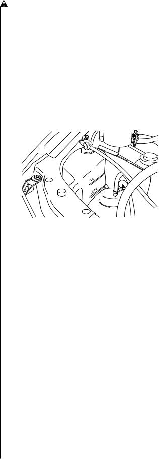
Engine coolant
Coolant level
WARNING
A)NEVER REMOVE THE RADIATOR CAP WHILE THE ENGINE IS HOT.
B)WRAP A THICK CLOTH AROUND THE CAP WHEN REMOVING IT.
1.Verify that the coolant level is near the radiator filler neck.
2.Check that the level in the coolant reservoir is between the “Full” and “Low” marks.
AV2A10020
3. Add coolant if necessary.
Coolant quality
1.Verify that there is no build up of rust or scale around the radiator cap of radiator filler neck.
2.Verify that the coolant is free of oil.
3.Replace the coolant if necessary.

ON-VEHICLE SERVICE PROCEDURE
Drive belt
Inspection
1.Check the drive belts for wear, cracks, and fraying. Replace if necessary.
2.Verify that the drive belts are correctly mounted on the pulleys.
3. Verify that “ |
|
mark. If two |
|
auto-tensioner is good. If not align as shown , re- |
|
install the |
tensioner or replace the drive belt. |
2 |
1 |
|
AV2A10B001 |
4. Check the |
drive belt deflection by applying |
moderate pressure (22 lb, 98 N, 10 kg) midway
AV2A10B002
between the pulleys.
 Caution
a)Measure the belt deflection between the pulleys.
b)Consider the belt as a new one if it has been used on a running engine for less than five minutes.
c)Check the belt deflection when the engine is cold or at least 30 minutes after the engine is stopped.
A/C belt deflection:
New one: 0.28~0.35 in (7~9 mm)
Used one: 0.35~0.43 in (9~11 mm)
EM-9
Adjustment
AN9010018-1
1.Loosen the idler pulley mounting bolt.
2.Adjust the belt deflection by turning the adjusting bolt.
Deflection (When applying 22 lb, 98 N, 10 kg) New one: 0.28~0.35 in (7~9 mm)
Used one: 0.35~0.43 in (9~11 mm)
3.After making the adjustment, tighten the idler pulley mounting bolt.
Tightening torque:
28~38 lb-ft (37~52N•m, 3.8~5.3 kg-m)
Replacement
1.Raise the vehicle and support it with safety stands.
2.Remove the RH side wheel.
3.Loosen the idle pulley mounting bolt.
4.Remove the A/C drive belt.
5.Lower the auto tensioner with spanner and then remove the drive belt.
AV2A10B038
6.Lower the auto tensioner with spanner and then install the drive belt.
7.Install the A/C drive belt.
8.Check the A/C drive belt deflection.
EM-10 |
ENGINE (KJ2.9 TCI DOHC DIESEL-COMMON RAIL SYSTEM) |
|
|
Timing belt
Removal
1.Raise vehicle and support it with safety stands.
2.Remove the radiator upper hose.
3.Remove the fuel filter hoses still connected.
4.Remove the No.3 engine mounting rubber.
No.3 engine mounting rubber
AV2A10B039A
5. Remove the No.3 engine mounting bracket.
AV2A10B040
6.Remove the RH side wheel.
7.Remove the A/C drive belt.
8.Remove the drive belt.
9.Remove the auto tensioner.
10.Remove the water pump pulley.
11.Remove the crankshaft pulley.
12.Remove the upper timing belt cover.
13.Remove the lower timing belt cover.
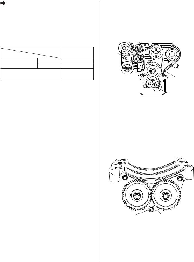
14.Rotate crankshaft and align timing mark on timing belt pulley with timing mark on engine block.
Camshaft pulleys
EX |
IN |
IN |
EX |
Crankshaft |
High pressure |
|
pump pulley |
||
pulley |
||
|
||
|
BV2A10B001 |
15.Remove the auto tensioner.
16.Remove the timing belt.
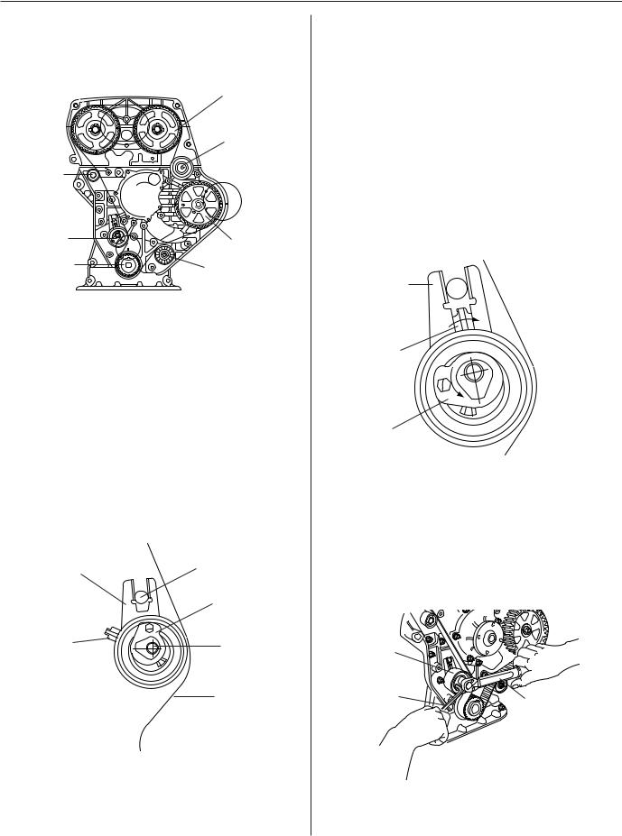
ON-VEHICLE SERVICE PROCEDURE
Replacement
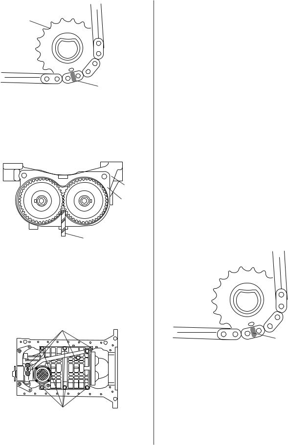
1.Check that timing mark on timing belt pulley, camshaft pulley and high pressure pump pulley is aligned with timing mark on engine.
Camshaft pulleys
EX |
IN |
|
Idler No.1 |
IN |
EX |
Touch
idler
Auto |
High |
|
tensioner |
||
pressure |
||
|
||
Crankshaft |
pump pulley |
|
pulley |
Idler No.2 |
|
|
BV2A10B001 |
2.Install the timing belt.
1)The timing belt is installed in sequence crank shaft pulley, idler No.2, high pressure pump pulley, idler No.1 and camshaft pulley.
Notice
a)The auto-tensioner must be mounted onto the engine after the timing belt is installed.
b)Keep the tension of timing belt when install timing belt.
3.Install the auto-tensioner.
1)Install the auto-tensioner as shown illust. The dowel pin has to be located between the tensioner fork (back plate).
Back plate |
Dowel pin |
|
Special washer
Pointer |
Lock bolt |
|
Timing belt
BV2A10B004
2) Pretighten the auto-tensioner.
Tightening torque:
2.9lb-ft (3.9N•m , 0.4kg-m)
EM-11
Notice
a)Oil must not get in contact with the tensioner. The tensioner has to be replaced by a new one, if it is oily.
b)The positions of the pointer, the back plate and the special washer are in accordance to the illust.
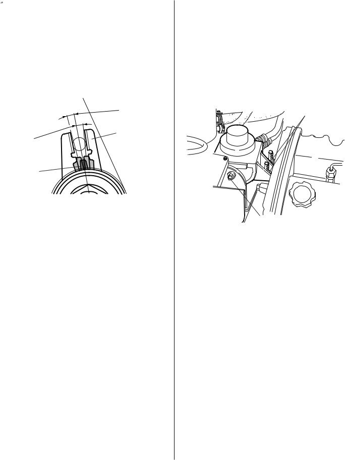
4.Check again if the alignment marks of camshafts, crankshaft and high pressure pump are aligned with the marks on the timing case.
5.Adjust the auto-tensioner, and then tighten it.
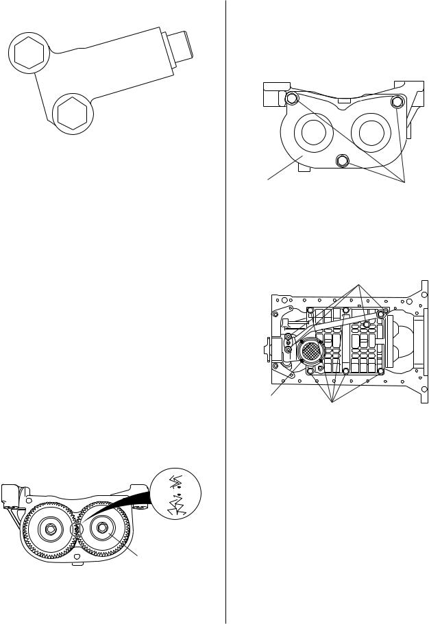
1)Align the pointer to the back plate by rotating the special washer in counter-clockwise using the hexagon wrench as shown illust.
Back plate
Pointer
Special washer
BV2A10B005
2)Tighten the auto-tensioner lock bolt with holding the special washer by the hexagon wrench when the pointer is aligned with the back plate.
Tightening torque :
17.4lb-ft (23.5N•m , 2.4kg-m)
Pointer |
|
Hexagon |
Torque wrench |
wrench |
BV2A10B006
3) Remove the hexagon wrench.
EM-12 |
ENGINE (KJ2.9 TCI DOHC DIESEL-COMMON RAIL SYSTEM) |
|
|
Notice
If the pointer can not be aligned with the back plate, then a new belt has to be used.
6.Rotate the crankshaft two full revolutions in clockwise to align the TDC mark.
7.Check again if the alignment marks of camshafts, crankshaft and high pressure pump are aligned with the marks on the timing case.
8.Check the alignment of the pointer and back plate.
Back plate
Pointer
BV2A10B007
Allowance misalignment :  5°
5°
9.If the misalignment between pointer and back plate is bigger than  5°, repeat step 4~8.
10.Install the upper and lower timing belt cover.
Tightening torque:
5.1~7.2 lb-ft (6.9~9.8 N•m, 70~100 kg-cm)
11.Install the crankshaft pulley.
Tightening torque:
253~289 lb-ft (343~392 N•m, 35~40 kg-m)
12.Install the water pump pulley.
Tightening torque:
13.0~20.9 lb-ft (17.6~28.4 N•m, 1.8~2.9 kg-m)
13.Install the auto tensioner.
Tightening torque:
13.0~20.9 lb-ft (17.6~28.4 N•m, 1.8~2.9 kg-m)
14.Install the drive belt and A/C drive belt.
15.Install the RH side wheel.
Tightening torque:
65~79 lb-ft (88~108 N•m, 9.0~11.0 kg-m)
16.Install the No.3 engine mounting bracket.
Tightening torque:
26.7~39.8 lb-ft (36.2~53.9 N•m, 3.7~5.5 kg-m)
17.Install the No.3 engine mounting rubber.
Tightening torque:
Nut: 49.1~68.7 lb-ft (66.7~93.1 N•m, 6.8~9.5 kg-m) Bolt: 62.9~86.0 lb-ft (85.3~116.7 N•m, 8.7~11.9 kg-m)
Nut
Bolt |
AV2A10B039A |
|
18.Install the fuel filter.
19.Install the radiator hose.
20.Fill engine coolant with specified type and amount.
21.Start engine and then check for leaks.
|
|
|
|
ON-VEHICLE SERVICE PROCEDURE |
EM-13 |
Compression pressure
Inspection
1.Warm up the engine upto the normal operating temperature, then stop the engine and disconnect the connector of fuel cut solenoid.
2.Remove all injection pipes, nozzles and washers.
3.Attach the SST to the nozzle hole.
4.Measure the compression pressure during cranking.
|
Engine model |
KJ2.9 TCI DOHC |
Item |
|
COMMON RAIL SYSTEM |
Compression pressure |
Normal |
426.6(2943, 30)-200 |
psi (kPa, kg/cm2)-rpm |
Limit |
383.9(2649, 27)-200 |
Cylinder-to-cylinder pressure difference |
below 42.7(294,3.0) |
|
psi (kPa, kg/cm2) |
|
|
|
|
|
5.Do above step 3~4 again for each cylinder.
6.If the measure value is below the limit, consider it as abrasion or damage of piston and piston ring, misalignment of valve, damage of gasket, and etc..
Ladder frame and balance shaft
Removal
1.Remove oil pan.
2.Adjust the V groove TDC mark on the outside of pulley to the TDC mark “T” on the timing cover, by rotating the crank shaft pulley.
BTDC T 10
Adjust the
TDC mark
Designate the position with marking pen
AV2A10B031
3.For timing check, loosen the 3 balance gear cover bolts on the back of ladder frame and check the balance gear assembly mark.
Notice
To prevent the balance shaft from being falled out, tighten the 1 of 3 balance gear cover bolts by hand into the thrust plate center.
Gear cover bolt |
Thrust plate |
AV2A10B006 |
|
|
4.When reassembling after checking the balance gear assembly mark, mark the chain link with marking pen that is matched with Ø0.12 in (3 mm) round TDC mark to adjust the timing.
Notice
Disregard the 2 yellow points on the chain link because
it is only available for engine assembly.
EM-14 |
ENGINE (KJ2.9 TCI DOHC DIESEL-COMMON RAIL SYSTEM) |
|
|
Balancer sprocket
Marking
AV2A10B032
5.Loosen balance sprocket bolt.
Notice
Insert the 0.2 in (5 mm) urethane rubber between balance gear to prevent the balance shaft from rotating and the balance gear from damaging.
LH RH
Ladder frame
Thrust plate
Urethane rubber
AV2A10B033
6.When disassembling the balance sprocket, hold the balance sprocket by one hand with pushing the thrust plate slightly then the balance separates from the neck of balance shaft.
7.When disassembling ladder frame, separate the oil feeding pipe from the oil pump by loosening the oil feeding pipe bolt.
Oil feeding pipe bolt
Ladder frame fastener bolt
AV2A10B036
8.Loosen the ladder frame fastener bolt. Remove ladder frame.
Replacement
1.Measure end play of balance shaft.
End play: 0.0039~0.0098 in (0.1~0.25 mm)
2.Install the balance shaft and thrust plate assembly into the ladder frame.
Notice
To prevent the balance shaft from being falled out, tighten the 1 of 3 balance gear cover bolts by hand into the thrust plate center.
3.Install the ladder frame into block. Check the dowel pin of ladder frame is matched with lower surface of block and insert the oil level gauge into the ladder frame hole.
Tightening torque (ladder frame bolt):
32.5lb-ft (44 N•m, 4.5 kg-m)
4.Install crankshaft sprocket, oil pump sprocket, guide and chain tensioner.
5.Adjust balance shaft sprocket position mark with chain link mark, and then insert the sprocket into the neck of balance shaft.
Notice
For smooth operation, pull the thrust plate out and hold, and then push the sprocket into the balance shaft.
Marking
AV2A10B032
6.Push the end of chain tensioner plunger utmost and then install the chain tensioner lever between chain and chain tensioner.
ON-VEHICLE SERVICE PROCEDURE |
EM-15 |
|
|
AV2A10B027A
7.Tighten balance sprocket bolt.
Notice
Insert the 0.2 in (5 mm) urethane rubber between balance gear to prevent the balance shaft from rotating and the balance gear from damaging.
Tightening torque: |
|
|
Mark 10T: |
50.6 lb-ft (68.6 |
N•m, 7 kg-m) |
Mark 8T: |
43.4 lb-ft (58.8 |
N•m, 6 kg-m) |
8.Rotate the crankshaft pulley 2 times and make the chain 1 rotating fully, check the adjustment between crankshaft pulley TDC mark and timing cover TDC mark after checking the balance gear assembly mark. If not, readjustment is needed.
Notice
The chain link mark position is only efficient to assembly, but it is not matched after 2 rotation of crankshaft pulley.
Timing check is only possible through the balance shaft gear.
LH  RH
RH
Balance shaft gear
AV2A10B081
9.Loosen the bolt on the thrust plate, and install the gear cover and tighten 3 bolts.
Tightening torque:
16.6lb-ft (23 N•m, 2.3 kg-m)
LH RH
Gear cover |
16.6 Ib-ft (23N•m, 2.3 kg-m) |
AV2A10B035
10.Install the oil feeding pipe into the ladder frame, oil pump and block and then tighten bolts.
16.6 lb-ft (23 N•m, 2.3 kg-m) Oil feeding pipe bolt
Oil strainer
Ladder frame bolt
32.5 lb-ft (44 N•m, 4.5 kg-m)
AV2A10B036
11.Install the oil pan.
12.Fill engine oil with specified type and amount.
13.Start engine and then check for leaks.
 Loading...