


345

Operator’s manual (EPA II)
340 345 350
Please read the operator’s manual carefully and make sure you
understand the instructions before using the machine.
EEEEnnnngggglllliiiisssshh
hh

KEY TO SYMBOLS
Key to symbols
WARNING! Chain saws can be dangerous!
Careless or incorrect use can result in
serious or fatal injury to the operator or
others.
Please read the operator’s manual carefully
and make sure you understand the
instructions before using the machine.
Always wear:
• Approved protective helmet
• Approved hearing protection
• Protective goggles or a visor
Both of the operator ′ s hands must be used to
operate the chain saw. Please see page 30
in your "Chain saw operator ′ s safety
manual".
Never operate a chain saw holding it with one
hand only. Please see page 30 in your
"Chain saw operator ′ s safety manual".
Refuelling.
Filling with oil and adjusting oil flow.
Other symbols/decals on the machine refer to special
certification requirements for certain markets.
Contact of the guide bar tip with any object
should be avoided. Please see pages 12-21
in your "Chain saw operator ′ s safety
manual".
Tip contact may cause the guide bar to move
suddenly upward and backward, which may
cause serious injury. Please see pages 1221 in your "Chain saw operator ′ s safety
manual".
Switch off the engine by moving the stop
switch to the STOP position before carrying
out any checks or maintenance.
Always wear approved protective gloves.
Regular cleaning is required.
Visual check.
Protective goggles or a visor must be worn.
English
2 –

EPA II
CONTENTS
Contents
KEY TO SYMBOLS
Key to symbols .............................................................
CONTENTS
Contents ......................................................................
Before using a new chain saw ..................................... 3
SAFETY INSTRUCTIONS
Personal protective equipment .....................................
Machine ′ s safety equipment ........................................ 4
Checking, maintaining and servicing the machine ′ s
safety equipment ..........................................................
Cutting equipment ........................................................ 9
How to avoid kickback .................................................. 15
General safety precautions .......................................... 16
General working instructions ....................................... 17
WHAT IS WHAT?
What is what on the chain saw? ..................................
ASSEMBLY
Fitting the bar and chain .............................................. 24
FUEL HANDLING
Fuel ..............................................................................
STARTING AND STOPPING
Starting and stopping ...................................................
MAINTENANCE
Carburettor ...................................................................
Starter .......................................................................... 30
Air filter ......................................................................... 31
Spark plug .................................................................... 31
Muffler .......................................................................... 31
Needle bearing lubrication ........................................... 31
Adjustment of the oil pump .......................................... 32
Cooling system ............................................................ 32
”Air Injection” centrifugal cleaning ................................ 32
Winter use .................................................................... 32
Daily maintenance ....................................................... 33
Weekly maintenance .................................................... 33
Monthly maintenance ................................................... 33
TECHNICAL DATA
Technical data ..............................................................
FEDERAL EMISSION CONTROL WARRANTY
STATEMENT
YOUR WARRANTY RIGHTS AND OBLIGATIONS .....
2
3
4
7
23
25
27
29
34
36
Before using a new chain saw
• Please read the operator’s manual carefully.
• Check that the cutting equipment is correctly fitted and
adjusted. See instructions under the heading Assembly.
• Refuel, start the chain saw and check the carburettor
settings. See the instructions under the headings Fuel
Handling, Starting and Stopping, and Carburettor.
• Do not use the chain saw until sufficient chain oil has reached
the chain. See instructions under the heading Lubricating
cutting equipment.
IMPORTANT! If the carburettor mixture is too lean it greatly
increases the risk of engine failure. Poor maintenance of the air
filter will cause carbon build-up on the spark plug and lead to
starting difficulties. If the chain is improperly adjusted it will cause
increased wear or damage to the bar, drive sprocket and chain.
Maintenance, replacement, or repair of the emission control
devices and system may be performed by any nonroad engine
repair establishment or individual.
WARNING! Under no circumstances may the
design of the machine be modified without the
!
permission of the manufacturer. Always use
genuine accessories. Non-authorized
modifications and/or accessories can result in
serious personal injury or the death of the
operator or others. Your warranty may not cover
damage or liability caused by the use of nonauthorized accessories or replacement parts.
WARNING! A chain saw is a dangerous tool
if used carelessly or incorrectly and can
!
cause serious, even fatal injuries. It is very
important that you read and understand the
contents of this operator’s manual.
WARNING! The inside of the muffler contain
chemicals that may be carcinogenic. Avoid
!
contact with these elements in the event of a
damaged muffler.
WARNING! Long term inhalation of the
engine’s exhaust fumes, chain oil mist and
!
dust from sawdust can represent a health risk.
You will find the following labels on your machine:
The Emissions Compliance Period referred to on the
Emission Compliance label indicates the number of operating
hours for which the engine has been shown to meet Federal
emissions requirements. Category C = 50 hours, B = 125
hours, and A = 300 hours.
Husqvarna AB has a policy of continuous product
development and therefore reserves the right to modify the
design and appearance of products without prior notice.
For customer assistance call: 704-921-7000 or contact us at
our website: www.husqvarna.com
English
– 3

SAFETY INSTRUCTIONS
Personal protective equipment
WARNING! Most chain saw accidents
happen when the chain touches the
!
operator.
You must use approved personal protective
equipment whenever you use the machine.
Personal protective equipment cannot
eliminate the risk of injury but it will reduce
the degree of injury if an accident does
happen. Ask your dealer for help in choosing
the right equipment.
WARNING! Long or continuous exposure to
high noise levels may cause permanent
!
hearing impairment. Always wear approved
hearing protection when operating a chain
saw.
′′
Machine
This section describes the machine ′ s safety equipment, its
purpose, and how checks and maintenance should be carried
out to ensure that it operates correctly. See the ”What is
what?” section to locate where this equipment is positioned
on your machine.
!
• Chain brake and front hand guard
• Throttle lock
′′
s safety equipment
WARNING! Never use a machine that has
faulty safety equipment! Carry out the
inspection, maintenance and service
routines listed in this section.
• Protective helmet
• Hearing protection
• Protective goggles or a visor
• Gloves with saw protection
• Protective trousers with saw protection
• Boots with saw protection, steel toe-cap and non-slip sole
• Chain catcher
• Right hand guard
• Vibration damping system
• Stop switch
Generally clothes should be close-fitting without restricting
your freedom of movement.
• Always have a first aid kit nearby.
English
4 –
• Muffler
• Cutting equipment. See instructions under the heading
Cutting equipment.

SAFETY INSTRUCTIONS
Chain brake and front hand guard
Your chain saw is equipped with a chain brake that is
designed to stop the chain immediately if you get a kickback.
The chain brake reduces the risk of accidents, but only you
can prevent them.
Take care when using your saw and make sure the kickback
zone of the bar never touches any object.
• The chain brake (A) can either be activated manually (by
your left hand) or automatically by the inertia release
mechanism (a pendulum that swings independently of the
chain saw. On most of our models the front hand guard
acts as a counterweight in case of kickback).
The brake is applied when the front hand guard (B) is
pushed forwards.
This movement activates a spring-loaded mechanism that
tightens the brake band (C) around the engine drive
system (D) (clutch drum).
• You can also use the chain brake as a temporary brake
when you change position or if you put the chain saw
down for a short time! Apart from the fact that a chain saw
with a chain brake greatly reduces the risk of accidents
due to kickback, you should also apply the chain brake
manually if there is a risk of the chain accidentally hitting
anyone or anything close by.
• To release the chain brake pull the front hand guard
backwards, towards the front handle.
• Kickback can be very sudden and violent. Most kickbacks
are minor and do not always activate the chain brake. If
this happens you should hold the chain saw firmly and not
let go.
• The front hand guard is not designed solely to activate the
chain brake. Another important feature is that it reduces
the risk of the chain hitting your left hand if you lose grip
of the front handle.
• The chain brake must be engaged when the chain saw is
started.
• The way the chain brake is activated, either manually or
automatically by the inertia release mechanism, depends
on the force of the kickback and the position of the chain
saw in relation to the object that the kickback zone of the
bar strikes.
If you get a violent kickback while the kickback zone of the
bar is farthest away from you the chain brake will be
activated by the movement of the counterweight (inertia
activated) in the kickback direction.
If the kickback is less violent or the kickback zone of the
bar is closer to you the chain brake will be activated
manually by the movement of your left hand.
English
– 5

SAFETY INSTRUCTIONS
• During felling your left hand grasps the front handle in
such a way that it cannot activate the chain brake. In this
position, i.e. when your left hand is in such a position that
it cannot affect the movement of the front hand guard, the
chain brake can only be activated by the inertia of the
counterweight.
• The inertia activated chain brake is a valuable feature but
there are certain factors to remember (see point above).
Throttle lock
Vibration damping system
Your machine is equipped with a vibration damping system
that is designed to minimize vibration and make operation
easier.
When you use a chain saw, vibration is generated by the
uneven contact between the chain and the wood you are
cutting.
Cutting hardwoods (most broadleaf trees) creates more
vibration than cutting softwoods (most conifers). Cutting with
cutting equipment that is blunt or faulty (wrong type or badly
sharpened) will increase the vibration level. See instructions
under the heading Cutting equipment.
The throttle lock is designed to prevent accidental operation
of the throttle control. When you press the lock (A) (i.e. when
you grasp the handle) it releases the throttle control (B).
When you release the handle the throttle control and the
throttle lock both move back to their original positions. This
movement is controlled by two independent return springs.
This arrangement means that the throttle control is
automatically locked at the idle setting.
Chain catcher
The chain catcher is designed to catch the chain if it snaps or
jumps off. This should not happen if the chain is properly
tensioned (see instructions under the heading Assembly) and
if the bar and chain are properly serviced and maintained
(see instructions under the heading General working
instructions).
The machine ′ s vibration damping system reduces the transfer
of vibration between the engine unit/cutting equipment and
the machine ′ s handle unit. The body of the chain saw,
including the cutting equipment, is insulated from the handles
by vibration damping units.
WARNING! Overexposure to vibration can
lead to circulatory damage or nerve damage
!
in people who have impaired circulation.
Contact your doctor if you experience
symptoms of overexposure to vibration.
Such symptoms include numbness, loss of
feeling, tingling, pricking, pain, loss of
strength, changes in skin colour or
condition. These symptoms normally appear
in the fingers, hands or wrists. The risk
increases at low temperatures.
Right hand guard
Apart from protecting your hand if the chain jumps or snaps,
the right hand guard stops branches and twigs from
interfering with your grip on the rear handle.
English
6 –
Stop switch
Use the stop switch to switch off the engine.

SAFETY INSTRUCTIONS
Muffler
The muffler is designed to keep noise levels to a minimum
and to direct exhaust fumes away from the user.
WARNING! The exhaust fumes from the
engine are hot and may contain sparks which
!
can start a fire. Never start the machine
indoors or near combustible material!
In areas with a hot, dry climate there is a high risk of fires.
These areas are sometimes controlled by legislation and
requirements that among other things the muffler must be
equipped with an approved type of spark arrestor mesh.
For mufflers it is very important that you follow the instructions
on checking, maintaining and servicing your machine. See
instructions under the heading Checking, maintaining and
servicing the machine’s safety equipment.
Checking the front hand guard
Make sure the front hand guard is not damaged and that there
are no visible defects such as cracks.
Move the front hand guard forwards and back to make sure it
moves freely and that it is securely anchored to the clutch
cover.
Checking the inertia brake release
WARNING! The muffler gets very hot in use
and remains so for a short time afterwards.
!
Do not touch the muffler if it is hot!
Checking, maintaining and servicing
the machine
WARNING! All servicing and repair work on
the machine requires special training. This is
!
especially true of the machine
equipment. If your machine fails any of the
checks described below you must contact
your service agent. When you buy any of our
products we guarantee the availability of
professional repairs and service. If the
retailer who sells your machine is not a
servicing dealer, ask him for the address of
your nearest service agent.
Chain brake and front hand guard
Checking brake band wear
Brush off any wood dust, resin and dirt from the chain brake
and clutch drum. Dirt and wear can impair operation of the
brake.
′′
s safety equipment
′′
′′
′′
s safety
Hold the chain saw over a stump or other firm object. Let go
of the front handle so that the bar drops towards the stump as
the chain saw rotates around the rear handle.
When the bar hits the stump the brake should be applied.
Checking the brake trigger
Place the chain saw on firm ground and start it. Make sure the
chain does not touch the ground or any other object. See the
instructions under the heading Start and stop.
Regularly check that the brake band is at least 0.6 mm thick
at its thinnest point.
English
– 7

SAFETY INSTRUCTIONS
Grasp the chain saw firmly, wrapping your fingers and thumbs
around the handles.
Apply full throttle and activate the chain brake by tilting your
left wrist forward onto the front hand guard. Do not let go of
the front handle. The chain should stop immediately.
Throttle lock
• Make sure the throttle control is locked at the idle setting
when the throttle lock is released.
Chain catcher
Check that the chain catcher is not damaged and is firmly
attached to the body of the chain saw.
Right hand guard
Check that the right hand guard is not damaged and that
there are no visible defects, such as cracks.
• Press the throttle lock and make sure it returns to its
original position when you release it.
• Check that the throttle control and throttle lock move freely
and that the return springs work properly.
• Start the chain saw and apply full throttle. Release the
throttle control and check that the chain stops and
remains stationary. If the chain rotates when the throttle
control is in the idle position you should check the
carburettor idle adjustment.
Vibration damping system
Regularly check the vibration damping units for cracks or
deformation.
Make sure the vibration damping units are securely attached
to the engine unit and handle unit.
Stop switch
Start the engine and make sure the engine stops when you
move the stop switch to the stop setting.
8 –
English

SAFETY INSTRUCTIONS
•
Muffler
Never use a machine that has a faulty muffler.
Regularly check that the muffler is securely attached to the
machine.
If the muffler on your machine is fitted with a spark arrestor
mesh this must be cleaned regularly. A blocked mesh will
cause the engine to overheat and may lead to serious
damage.
• Keep the chain’s cutting teeth properly sharpened!
Follow our instructions and use the recommended file
gauge. A damaged or badly sharpened chain increases
the risk of accidents.
• Maintain the correct raker clearance! Follow our
instructions and use the recommended raker gauge.
Too large a clearance increases the risk of kickback.
• Keep the chain properly tensioned! If the chain is slack
it is more likely to jump off and lead to increased wear on
the bar, chain and drive sprocket.
• Keep cutting equipment well lubricated and properly
maintained! A poorly lubricated chain is more likely to
break and lead to increased wear on the bar, chain and
drive sprocket.
Never use a muffler if the spark arrestor mesh is missing
or defective.
WARNING! Never use a machine with faulty
safety equipment. The machine’s safety
!
equipment must be checked and maintained
as described in this section. If your machine
fails any of these checks contact your
service agent to get it repaired.
Cutting equipment
This section describes how to choose and maintain your
cutting equipment in order to:
• Reduce the risk of kickback.
• Reduce the risk of the chain breaking or jumping.
• Obtain maximum cutting performance.
• Extend the life of cutting equipment.
General rules
Only use cutting equipment recommended by us!
See the Technical data section.
Cutting equipment designed to minimise kickback
WARNING! Faulty cutting equipment or the
wrong combination of bar and chain
!
increases the risk of kickback! Use only the
bar and chain combinations that we
recommend. See the Technical data section.
The only way to avoid kickback is to make sure that the
kickback zone of the bar never touches anything.
By using cutting equipment with ”built-in” kickback reduction
and keeping the chain sharp and well-maintained you can
reduce the effects of kickback.
Bar
The smaller the tip radius the smaller the kickback zone and
the lower the chance of kickback.
English
– 9

SAFETY INSTRUCTIONS
Chain
A chain is made up of a number of links, which are available
in standard and low-kickback versions.
None
Cutting link
Drive link
Side link
Combining these links in different ways gives different
degrees of kickback reduction. In terms of kickback reduction
alone, four different types of link are available.
Level of
kickback
reduction
Low
Cutting link Drive link Side link
Standard Low-kickback
• Number of drive links. The number of drive links is
determined by the length of the bar, the chain pitch and
the number of teeth on the bar tip sprocket.
• Bar groove width (inches/mm). The groove in the bar must
match the width of the chain drive links.
• Chain oil hole and hole for chain tensioner. The bar must
be matched to the chain saw design.
Chain
• Chain pitch (inches)
Standard
High
Extra high
Some terms that describe the bar and chain
When the cutting equipment supplied with your saw becomes
worn or damaged you must replace it with one of the bars and
chains recommended by us. See the Technical data section.
Bar
• Length (inches/cm)
• Number of teeth on bar tip sprocket (T). Small number =
small tip radius = low risk of kickback.
• Drive link width (mm/inches)
• Number of drive links.
• Level of kickback reduction. The level of kickback
reduction offered by a chain is only indicated by its model
number. See the Technical data section to find the model
numbers of chains that are recommended for use with
your model of chain saw.
• Chain pitch (inches). The spacing between the drive links
of the chain must match the spacing of the teeth on the
bar tip sprocket and drive sprocket.
English
10 –

SAFETY INSTRUCTIONS
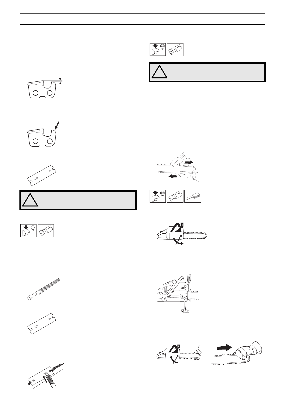
Sharpening your chain and adjusting raker clearance
WARNING! The risk of kickback is increased
with a badly sharpened chain!
!
General information on sharpening cutting teeth
• Never use a blunt chain. When the chain is blunt you have
to exert more pressure to force the bar through the wood
and the cuttings will be very small. If the chain is very blunt
it will not produce any cuttings at all. Wood powder would
be the only result.
• A sharp chain eats its way through the wood and
produces long, thick cuttings.
• The cutting part of the chain is called the cutting link and
this consists of a cutting tooth (A) and the raker lip (B). The
cutting depth is determined by the difference in height
between the two.
It is very difficult to sharpen a chain correctly without the right
equipment. We recommend that you use our file gauge. This
will help you obtain the maximum kickback reduction and
cutting performance from your chain.
See the Technical data section for information about
sharpening your chain.
WARNING! The following faults will increase
the risk of kickback considerably:
!
File angle too large
Cutting angle too small
File diameter too small
When you sharpen a cutting tooth there are five important
factors to remember.
1 Filing angle
2 Cutting angle
3 File position
4 Round file diameter
Sharpening cutting teeth
To sharpen cutting teeth you will need a round file and a file
gauge. See the Technical data section for information on the
size of file and gauge that are recommended for the chain
fitted to your chain saw.
•
Check that the chain is correctly tensioned. A slack chain will
move sideways, making it more difficult to sharpen correctly.
• Always file cutting teeth from the inside face. Reduce the
pressure on the return stroke. File all the teeth on one side
first, then turn the chain saw over and file the teeth on the
other side.
5 File depth
• File all the teeth to the same length. When the length of
the cutting teeth is reduced to 4 mm (0.16") the chain is
worn out and should be replaced.
English – 11
SAFETY INSTRUCTIONS
General advice on setting raker clearance
• When you sharpen the cutting teeth you reduce the raker
clearance (=cutting depth). To maintain optimal cutting
performance you must file back the raker lip to the
recommended height.
See the Technical data section to find the raker clearance
for your particular chain.
• On a low-kickback cutting link the front edge of the raker
lip is rounded. It is very important that you maintain this
radius or bevel when you adjust the raker clearance.
• We recommend that you use our raker gauge to achieve
the correct clearance and bevel on the raker lip.
Tensioning the chain
WARNING! A slack chain may jump off and
cause serious or even fatal injury.
!
The more you use a chain the longer it becomes. It is
therefore important to adjust the chain regularly to take up the
slack.
Check the chain tension every time you refuel. NOTE! A new
chain has a running-in period during which you should check
the tension more frequently.
The position of the chain tensioning screw on our chain saws
varies from model to model. See the What is what? section to
find out where it is on your model.
Tension the chain as tightly as possible, but not so tight that
you cannot pull it round freely by hand.
WARNING! The risk of kickback is increased
if the raker clearance is too large!
!
Setting the raker clearance
• Before setting the raker clearance the cutting teeth should
be newly sharpened. We recommend that you adjust the
raker clearance every third time you sharpen the chain.
NOTE! This recommendation assumes that the length of
the cutting teeth is not reduced excessively.
• To adjust the raker clearance you will need a flat file and a
raker gauge.
• Place the gauge over the raker lip.
• Place the file over the part of the lip that protrudes through
the gauge and file off the excess. The clearance is correct
when you no longer feel any resistance as you draw the
file over the gauge.
• Undo the bar nuts that hold the clutch cover/chain brake.
Use the combination spanner. Then tighten the bar nuts
by hand as tight as you can.
• Raise the tip of the bar and stretch the chain by tightening
the chain tensioning screw using the combination
spanner. Tighten the chain until it does not sag from the
underside of the bar.
• Use the combination spanner to tighten the bar nuts while
lifting the tip of the bar at the same time. Check that you
can pull the chain round freely by hand and that it does not
sag from the underside of the bar.
12 – English
 Loading...