


 Loading...
Workshop manual
343R 345RX
343F 345FX 345FXT
English

Workshop Manual
Brushcutter, Trimmer
Model 343R, 345RX, 343F, 345FX, 345FXT
Contents
General recommendations ___________________ 2
1.Starter __________________________________ 3
2.Electrical system _________________________ 7
3.Fuel system _____________________________ 15
4.Centrifugal clutch ________________________ 31
5.Angle gear ______________________________ 37
6.Cylinder and piston ______________________ 41
7.Crankshaft and crankcase _________________ 51
8.Tools ___________________________________ 59
© Copyright Husqvarna AB, Sweden 2003
1

General recommendations
Remember: |
Special tools |
! Never start the engine without the clutch and clutch drum |
Certain tasks in this handbook require the use of special |
mounted. |
tools. In sections where this is applicable, an image of the |
! Do not grasp hot elements such as the muffler or the clutch |
tool with an ordering number is provided. |
before they have cooled sufficiently to avoid burn injuries. |
We recommend using special tools in order to avoid personal |
! Avoid getting petrol on you skin or in your mouth. Use |
injury and to eliminate expensive damage to the components |
protective cream on your hands. This lowers the risk of |
in question. |
infection and makes dirt easier to wash off. Long-term |
|
contact with engine oil can be damaging to your health. |
|
! Never run the engine indoors. The engine exhaust is poisonous! |
|
! Wipe up any spilled oil from the floor immediately in order to |
|
avoid injuries from slipping. |
|
! Do not use tools that are worn or fit poorly on nuts and bolts |
|
and so on. |
|
+ Always work on a clean work surface.
+Always work in a logical manner in order to be sure that all components are correctly attached and that nuts and bolts
are tightened.
+ Use special tools where recommended in order to work correctly.
502 51 03-01
Fire risk
Handle petrol with respect, since it is highly flammable.
Do not smoke and ensure that there are no open flames or sparks in the vicinity.
Make sure that there is a functioning fire extinguisher in the vicinity.
Do not try to extinguish a petrol fire with water.
Poisonous fumes
When using cleaning fluids, read the instructions carefully.
Make sure that ventilation is good when handling petrol, trichloroethylene and other highly volatile liquids.
The engine exhaust is poisonous. Test run the engine only if ventilation is good. Preferably outside.
!WARNING!
Risk of personal injury if the instructions are not followed.
Sealing faces and gaskets
Make sure that all sealing faces are clean and free from old gasket remnants. Use a tool that will not damage the sealing face when it is cleaned. Any scratches and irregularities should be removed with a fine, float-cut file.
Sealing rings
Always change a sealing ring once it has been dismounted. The sensitive sealing lips can be easily damaged with poor sealing ability as a result. The surfaces that the seal is to tighten against must also be completely free from damage. Lubricate the sealing lip with grease before it is attached and make sure that it is not damaged by such things as the collars and splines on an axle. Use tape or a conical bushing as protection. It is important that the sealing ring is turned correctly in order for it to function as intended.
NOTE!
Material damage may occur if the instructions are not followed.
2
1
Starter
1.
Contents
Dismantling _________________________________ 4
Assembly __________________________________ 5
Replacing the drive dogs ______________________ 6
3
1 |
Starter |
! |
WARNING!
Protective glasses should be worn when working on the starter to avoid injury to the eyes if, for some reason, the return spring should fly out.
Dismantling
Remove the starter from the engine.
502 50 18-01 |
Loosen the spring tension.
Dismantling
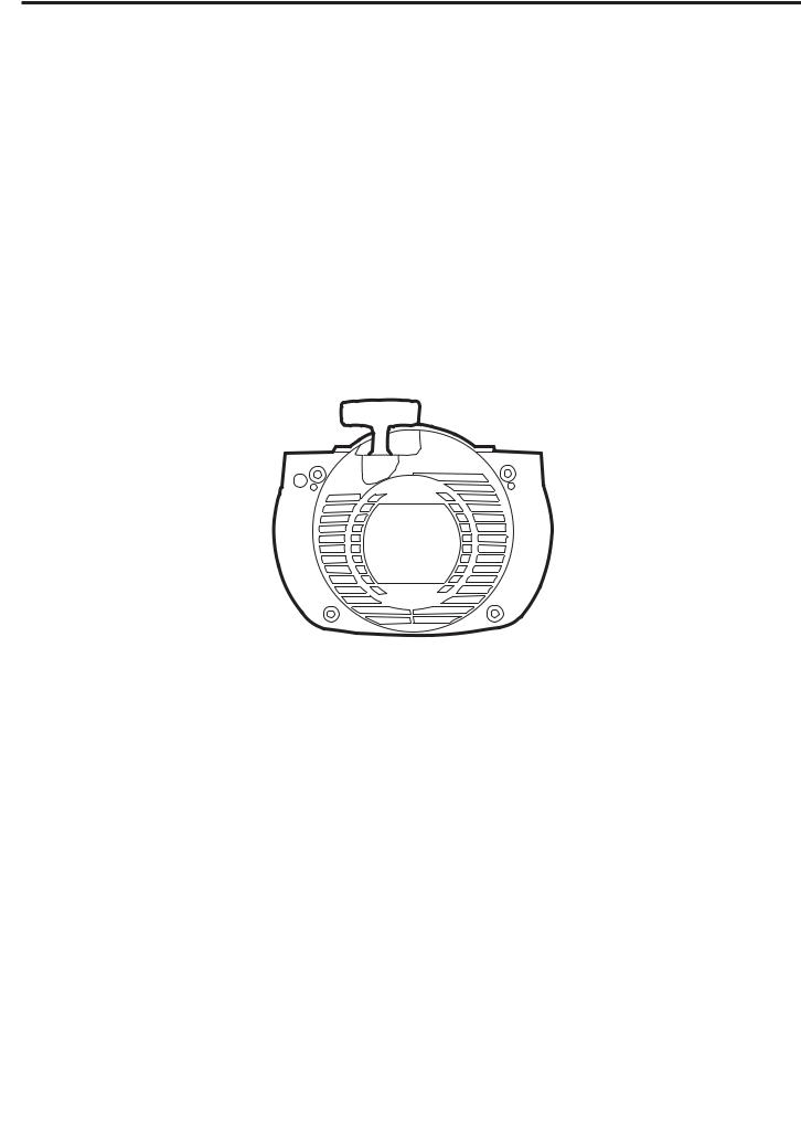
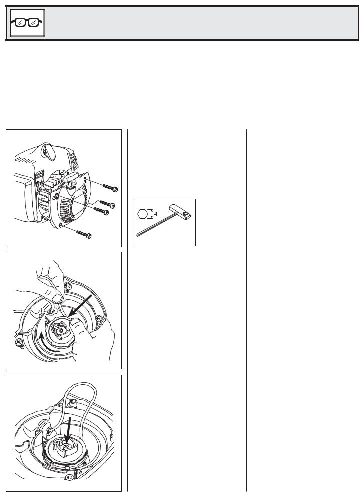
Remove the 4 bolts and lift off the starter.
The cylinder cover does not need to be loosened or detached.
Loosen the spring tension.
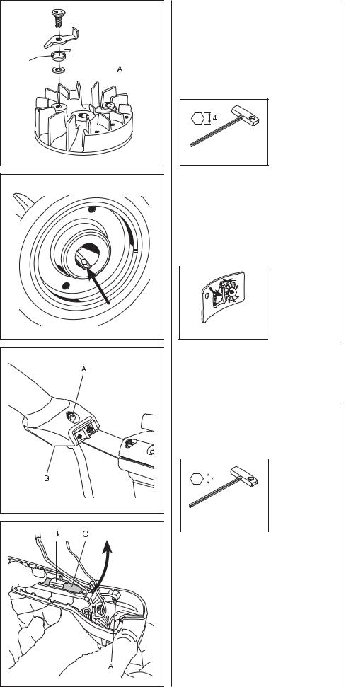
Pull out the starter cord about 30 cm. Brake the starter pulley with your thumb and lift the cord as illustrated.
Let the starter pulley rotate backwards slowly.
Remove the bolt in the centre of the starter pulley and remove the starter pulley.
Remove the bolt in the centre of the starter pulley. Lift the starter pulley carefully from the starter cover.
4

Starter |
1 |
||
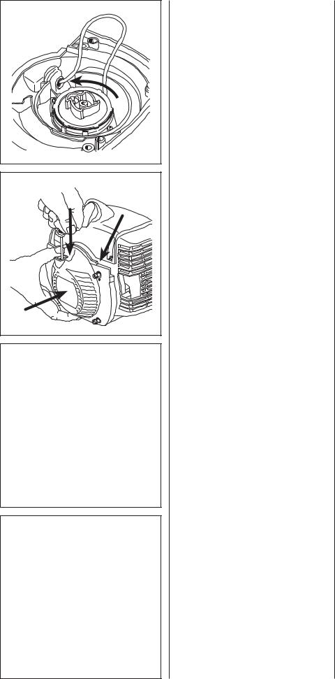
Remove the spring cassette. |
|
Remove the two bolts holding the |
|
|
|||
|
|
spring cassette and remove the |
|
|
|
cassette for replacement if necessary. |
|
|
|
|
|
!WARNING!
Wear protective glasses. The return spring can fly out and cause personal injury if improperly handled.
Assembly
Clean requisite parts and assemble in the reverse order as set out for dismantling.
Assembly
Clean all components before assembly:
Change return springs, starter pulley and starter cord as needed.
NOTE!
Be careful when opening the packaging with the return spring so that the spring does not fly out.
Attach the spring cassette. Attach the starter pulley. Attach the new starter cord.
Attach the spring cassette and tighten the two bolts (A).
Lubricate the bearing journal with a little grease and attach the starter pulley.
Place the washer in place and tighten the bolt.
Attach the new starter cord. Push it in to the starter pulley’s track as illustrated and then out through the cord guide in the starter cover. Make sure that the knot at the end of the cord is as small as possible!
NOTE!
New starter cords can be attached without dismantling the starter!
Anchor the cord in the starter handle.
Thread the cord through the starter handle and anchor it with a knot.
Fold down the free end and pull the knot well into the handle.
5
1 |
Starter |
Tighten the return spring. |
Tighten the return spring. |
Check the spring tension. |
Lift up the starter cord when the return |
|
spring is completely loose and the cord |
|
pulled out completely. |
|
Then turn the starter pulley anti- |
|
clockwise 7 revolutions. |
|
Check the spring tension. With the cord |
|
completely pulled out the cord pulley |
|
should be able to be turned at least |
|
another half revolution. |
Mount the starter onto the engine. |
Mount the starter onto the engine. |
|
Pull out the starter cord a little. |
|
Place the starter in position and release |
|
the starter cord at the same time. |
|
Check that the ignition cable is not |
|
trapped (see arrow). |
|
Check that the drive dogs grip the |
|
starter pulley in the correct way. |
|
Tighten the bolts. |
Replacing the drive |
Replacing the drive |
dogs |
dogs |
See chapter 2 Ignition system. |
See chapter 2 Ignition system. |
6
2
Electrical system
2.
Contents
Checking the ignition spark ____________________ 8
Replacing the spark plug cover ________________ 10
Dismantling ________________________________ 11
Drive dogs _________________________________ 12
Assembly _________________________________ 12
Heated handles_____________________________ 12
7

2 |
Electrical system |
The engine is equipped with an electronic ignition system completely without moving parts. Consequently, a faulty component cannot be repaired, but must be replaced by a new component.
The spark in an electronic ignition system has a very short burn time and can therefore be interpreted as weak and can be difficult to see while troubleshooting.
Checking the ignition spark
Clean the electrodes and check the electrode gap.
502 51 91-01
If the electrodes are worn more than 50% the spark plug should be changed.
Check if a spark occurs when attempting to start.
Test with test spark plug no. 502 71 1301 if no spark is seen.
502 71 13-01
Checking the ignition spark
Remove the spark plug and clean it from soot deposits with the help of a steel brush.
Check the electrode gap. It should be 0.5 mm.
Adjust the gap as needed to the correct value with the side electrode.
If the electrodes are worn more than 50% the spark plug should be changed.
Too large a spark gap entails a great deal of stress on the ignition module and risk for short-circuiting.
Also check that the stop switch is in the start position.
Earth the spark plug on the cylinder and pull sharply on the start handle.
A spark should be seen between the electrodes.
If no spark is seen test with test spark plug no. 502 71 13-01.
If a spark then occurs, the spark plug is faulty.
Try a new spark plug.
8

Electrical system |
2 |
If no spark occurs, disconnect the stop switch.
Replace the switch if necessary
The stop switch can be easily detached with a screwdriver.
Still no spark?
Check the ignition cable’s connection to the spark plug cover.
Still no spark?
Check other cables and connections.
If no spark occurs even now, remove the short-circuit cable from the connection point in the carburettor compartment.
If the plug now sparks, the fault is either in the stop switch or the short-circuit cable.
Change the switch as needed and check to see if the cable insulation is damaged.
The stop switch is easily reached when the cover is removed.
Use a screwdriver pinch the switch’s snap fastener inside the throttle.
Still no spark?
Check the spark plug connection.
Remove the spark plug cover and make sure the ignition cable is not damaged. Remove a segment of cable if required to get sufficient contact at the connection coil.
Still no spark?
Check other cables and connections for poor contacts (dirt, corrosion, cable breakage and damaged insulation).
Make sure that the cables are correctly drawn and lie in the cable grooves.
Do not forget to check the cables in the throttle too.
See chapter 3 “Throttle”.
Tip!
Use an Ohmmeter in order to easily check if cable breakage has occurred, due to pinching, for example.
9
2 |
Electrical system |
|
|
|
Still no spark? |
Still no spark? |
|
|
Check the air gap. |
Check the air gap between the flywheel |
|
|
|
magnet and the ignition module. The |
|
|
|
gap should be 0.3 mm. |
|
|
|
Use a 502 51 34-02 feeler gauge. |
|
|
0.3 |
|
|
|
502 51 34-02 |
|
|
|
Adjust the air gap. |
Adjust the air gap as needed to the |
|
|
|
correct value. |
|
|
|
• |
Loosen the bolts. |
|
|
• Position the feeler gauge and press |
|
|
|
|
the ignition module against the |
|
|
|
flywheel. |
|
|
• Tighten the bolts and check the air |
|
|
|
|
gap again. |
|
|
If the spark plug still does not fire, the |
|
|
|
ignition system should be replaced. |
|
Replacing the spark |
Replacing the spark |
|
plug cover |
plug cover |
|
1. Insert the ignition cable through the |
1. Lubricate the ignition cable with a |
|
spark plug cover. |
little grease and thread it through |
|
2. Make a hole in the ignition cable for |
the spark plug cover. |
|
|
||
the ignition coil. |
2. Cut off a bit of the ignition cable |
|
|
|
(approx. 5 mm) and make a hole in |
|
|
the cable for the ignition coil with |
|
|
the aid of a pair of no. 502 50 06-01 |
|
|
|
|
|
pliers. |
502 50 06-01 |
|
|
|
3. Attach the ignition coil to the ignition |
3. |
Attach the ignition coil to the ignition |
|
cable. |
|
cable and ensure that the wire is |
|
|
|
|
folded along the cable. |
|
|
4. |
Pull the ignition coil into the spark |
|
|
|
plug cover. |
NOTE!
It is important that the tip of the ignition coil hits the centre of the ignition cable to prevent sparking.
10

Electrical system |
2 |
Dismantling
Remove the starter, cylinder cover, and spark plug.
Attach piston stop no. 502 54 15-01.
502 54 15-01
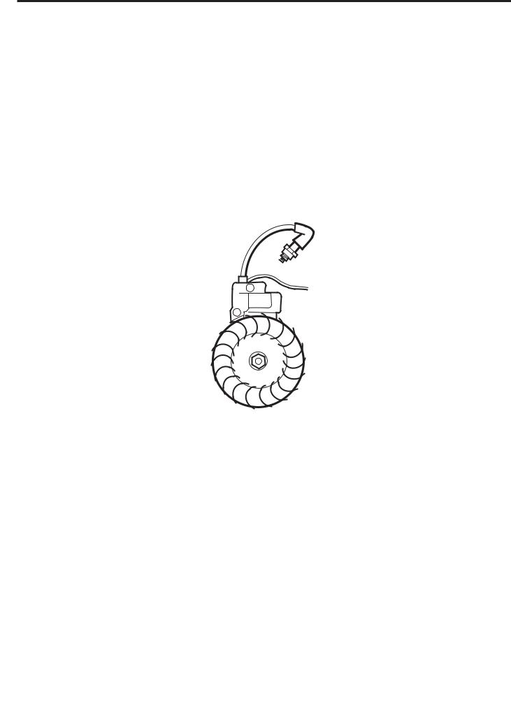
Remove the nut holding the flywheel.
Remove the flywheel.
502 51 94-01
Remove the ignition module and the generator.
502 50 18-01
Dismantling
Remove the starter, cylinder cover, and spark plug.
Fit piston stop no. 502 54 15-01 in the spark plug hole.
NOTE!
Place the piston stop so it is caught between the piston and the cylinder head. Not so it sticks out into the exhaust port.
Remove the nut holding the flywheel.
Remove the flywheel from the crankshaft using punch no. 502 51 94-01.
Leave a gap of approx. 2 mm between the punch and the flywheel.
Gently knock the punch with a hammer while holding the flywheel with your other hand.
Dismantle the ignition module.
Remove the ignition cable from the holder (A).
Remove both bolts (B).
Loosen the short-circuit cable (C) from the ignition module.
Remove the generator (D) that supplies power to the heated handles.
11
2 |
Electrical system |
Drive dogs
Remove the bolts.
Remove the hooks and the springs to replace them.
Mind the washer (A) so as not to lose it. Replace damaged parts.
Assemble in the reverse order.
502 50 18-01
Assembly
Check the key groove in the crankshaft and key in the flywheel. If damaged the components must be replaced.
Attach the ignition module and then the flywheel.
Check the air gap, see page 9.
0.3
502 51 34-02
Drive dogs
The drive dogs can be easily replaced if they are damaged.
Remove the bolts, the hooks and the springs.
Mind the washer (A) so as not to lose it. Replace damaged parts.
Assemble in the reverse order.
Check that the hooks can be turned freely when the bolts are tight.
Assembly
Check that the key groove in the crankshaft is not damaged. If it is, the crankshaft must be replaced.
Attach the ignition module and make sure the short-circuit cable is not trapped.
Check that the key in the flywheel is not damaged. If it is, the flywheel must be replaced.
Attach the flywheel.
Check the air gap, see page 9.
Heated handles
The heating element in the handles consists of ceramic plates. These are self-regulat- ing with regard to temperature. When temperature increases, the resistance in the elements lowers and so does the temperature. So no separate thermostat is needed.
Remove the throttle from the handle. |
Remove the throttle from the handle. |
||||
In order to have access, the bolt that |
See also chapter 3 “Throttle”. |
||||
holds the throttle and the cover with the |
In order to remove the heating element |
||||
circuit breaker must be removed to |
|||||
the bolt (A) that holds the throttle and |
|||||
reach the electrical cables. |
|||||
cover (B) and the heater switch must |
|||||
|
|
|
|
||
|
|
|
|
first be removed (2 bolts). |
|
|
|
|
|
||
|
|
|
|
|
|
|
|
|
|
|
|
|
|
|
|
|
|
|
|
|
|
|
|
502 50 18-01 |
|
|
|
The heating element in the throttle is |
A heating element is placed in the |
||
accessed when the throttle lock is |
throttle lock for involuntary throttling. |
||
pushed out of the throttle. |
Press the locking catch from the |
||
Pry off the locking catch and lift out the |
throttle, making sure not to lose the |
||
spring (A). |
|||
heating element. |
|||
|
|||
|
|
Pry off the locking catch (B) and lift out |
|
|
|
the heating element (C). |
|
|
|
|
|
|
|
NOTE! |
|
|
|
Do not pry off the heating element |
|
|
|
before the locking catch has been |
|
|
|
removed. The element can be |
|
|
|
damaged. |
|
|
|
|
|
12

Electrical system |
2 |
Separate the contacts (A-A) and (B-B).
Then extend the cables (A) and (B) with approx. 90 cm long steel wires attached to the contacts.
Remove the bolt and pull off the left grip from the handle.
Pull one cable at a time from the handle.
Remove the heating element from the handle with a pair of flat nosed pliers.
Separate the contacts (A-A) and (B-B).
Then extend the cables (A) and (B) with approx. 90 cm long steel wires attached to the contacts.
This is to make it easier to draw the cables to the new heating element back through the handle.
1 = black
2 = blue
Remove the bolt that holds the left grip on the handle.
Pull out handle from the handlebars and then the cables, carefully and one at a time, so that the steel wire does not loosen from the cables.
The heating element is located in a pocket in the outside of the handle.
Use flat nose pliers to pull out the heating element from the handle.
NOTE!
Do not pull the cables or their connections. Connections can be easily broken.
Assemble in the reverse order as set out for dismantling.
Wiring diagram
LH |
= |
Left handle |
RH |
= |
Throttle |
HC |
= |
Heater switch |
TT |
= |
Triple contact |
IM |
= |
Ignition module |
SC |
= |
Short-circuit switch |
Gen |
= |
Generator |
Blu |
|
= blue |
Bl |
|
= black |
Re |
|
= red |
Bl/Blu |
= black/blue |
|
Use a universal tool when checking wiring and heating elements. Set the instrument to measure resistance to check for open circuits.
13

|
2 |
Electrical system |
|
|
|
|
|
|
|
|
|
14
3
Fuel system
3.
Contents
Air filter ___________________________________ 16
Tank venting _______________________________ 17
Fuel filter __________________________________ 17
Fuel pump _________________________________ 18
Carburettor ________________________________ 18
Assembly _________________________________ 24
Carburettor settings _________________________ 25
Throttle ___________________________________ 27
15

3 |
Fuel system |
|
|
|
|
In addition to the fuel tank and carburettor, the fuel system consists of the air filter, fuel filter and tank venting.
All these components interact so that the engine receives the optimal mixture of fuel and air to make it as efficient as possible. Very small deviations in the carburettor setting or a blocked air filter have a large effect on the running and efficiency of the engine.
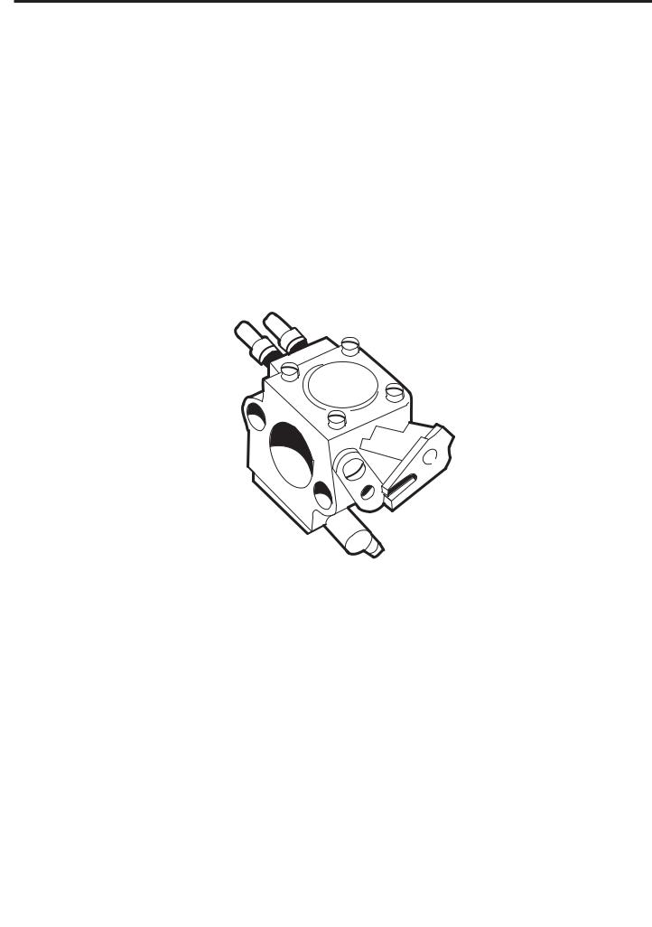
The carburettor can come from several different manufacturers on our models, but the function and repair methods are essentially the same.
Air filter |
Air filter |
Remove the air filter holder. |
Dismantle the cover (A) and remove the |
|
air filter (B). |
|
The nylon filter comes in two models. |
|
The standard filter has a mesh size of |
|
80µ. There is also a 44µ unit available. |
|
There is also a flock filter, also as an |
|
accessory. |
Separate the filter halves and clean the |
The air filter comes apart. Separate the |
nylon filter in warm soapy water. |
two halves with a screwdriver. |
The R-variant has a foam rubber filter. |
Clean the filter in warm soapy water. If |
|
the filter fabric is damaged the entire |
|
filter should be changed. |
|
The R-variant has a foam rubber filter. |
!WARNING!
Do not clean not the filter with petrol. Hazardous!
NOTE!
Do not blow the filter clean with compressed air. It can be damaged. Ensure that the filter is dry before refitting it.
16 |
Remove the foam rubber filter and clean it in warm soapy water.
Remove the foam rubber filter and clean it in warm soapy water.

Fuel system |
3 |
Impregnate the filter with air filter oil.
531 00 60-76
Tank venting
Check that the tank venting valve works correctly.
Replace the fuel cap if the valve is faulty.
531 03 06-23
Fuel filter
The fuel filter can be removed through the tank’s fill hole.
502 50 83-01
Impregnate the filter with air filter oil.
Tip!
Place the filter in a plastic bag and pour about a tablespoon of air filter oil no. 531 00 60-76 into the bag.
Massage the oil into the air filter.
Tank venting
Tank venting takes place through the fuel cap and needs to be functional for the engine to work.
•Remove the fuel hose from the carburettor and empty the fuel from the tank.
•Connect the fuel hose to pressure tester no. 531 03 06-23.
•Pump up a pressure and vacuum of 50 kPa (0.5 bar) in the tank.
•The pressure should sink to 20 kPa or return to normal pressure within 45 seconds.
The fuel cap can be taken apart for cleaning.
Use a screwdriver and prise off the housing (A) that contains a rubber diaphragm (B) and a filter (C).
Knock the housing against a tabletop so that the cover (D) over the diaphragm falls off.
Blow the filter (C) clean, and the sintered filter (E), with compressed air and mount the fuel cap in the reverse order to how it was disassembled.
Make sure that the flat surface on the cover (D) is turned towards the diaphragm.
Fuel filter
The fuel hose in the tank contains a fuel filter. It is accessible through the fill hole. Pull out the filter with your fingers or with help of tool 502 50 83-01.
NOTE!
The fuel filter can snag under the shaft bushing in the tank. With the aid of a long screwdriver, loosen the filter. Do not pull on the hose, since it can easily be pulled from the filter.
17

3 |
Fuel system |
18 |
Clean the filter externally if it is not too |
If the filter is not too dirty, its surface |
dirty. |
can be cleaned with a brush. |
Replace the filter if required. |
Otherwise it must be replaced. |
|
Check the fuel hose for cracks and |
|
leaks. |
|
Make sure that the filter’s connection |
|
neck is inserted as far as possible into |
|
the fuel hose and that the O-ring is |
|
sufficiently tight so that the filter cannot |
|
slide off the tube. |
Fuel pump |
Fuel pump |
|
The fuel pump facilitates cold starts. |
The fuel pump has the task of facilitat- |
|
The pump cannot be repaired and must |
ing the start of the engine when cold. |
|
The pump fills the carburettor with fuel |
||
be replaced if it stops working. |
||
before attempting to start the engine. |
||
Note how the fuel hoses are connected |
||
This also prevents vapour bubbles from |
||
to simplify assembly. |
||
blocking the narrow fuel channels. |
||
|
||
|
If the pump does not work it must be |
|
|
replaced. |
|
|
Note how the fuel hoses are connected |
|
|
to simplify assembly. |
Carburettor |
Carburettor |
||||||
Dismantling |
Dismantling |
||||||
Blow clean the carburettor compartment. |
1.Remove the carburettor cover and |
||||||
Loosen the bolts (A) and remove the |
blow the carburettor compartment |
||||||
clean with compressed air. |
|||||||
nuts (B). |
|||||||
|
|
||||||
Remove the fuel hose (C) and fold the |
2.Loosen the bolts (A). |
||||||
|
|
||||||
filter holder aside. |
3.Remove the nuts (B). |
||||||
|
|
|
|
|
4.Remove the fuel hose (C) from the |
||
|
|
|
|
|
|
carburettor and the filter holder. |
|
|
|
|
|
|
|
||
|
|
|
|
|
|
|
|
|
|
|
|
|
|
|
|
|
|
|
|
|
|
|
|
|
|
|
|
|
|
|
|
505 38 13-08 |
|
502 50 18-01 |
|
|
|
Move the fuel tank so far forward that |
5. |
Move the fuel tank so far forward |
|||
the fuel hoses (C) and (D) can be |
|
that the fuel hose (C) becomes |
|||
removed. |
|
|
|
accessible. |
|
|
|
|
|
Move the O-ring back and remove |
|
|
|
|
|
the hose from the nipple. |
|
|
|
|
|
Also remove the fuel hose (D) from |
|
|
|
|
|
the nipple on the tank. |
|
|
|
|
|
|
|
Loading...