

Page 1

HP NetServer
Common Tray Ultra3
Hard Disk Drive
Installation Guide
HP Part Number 5969-5921
Printed in February 2000
Page 2

Notice
The information contained in this document is subject to change without notice.
Hewlett-Packard makes no warranty of any kind with regard to this
material, including, but not limited to, the implied warranties of
merchantability and fitness for a particular purpose. Hewlett-Packard shall
not be liable for errors contained herein or for incidental or consequential
damages in connection with the furnishing, performance, or use of this material.
Hewlett-Packard assumes no responsibility for the use or reliability of its software
on equipment that is not furnished by Hewlett-Packard.
This document contains proprietary information that is protected by copyright.
All rights are reserved. No part of this document may be photocopied,
reproduced, or translated to another language without the prior written consent of
Hewlett-Packard Company.
®
NetWare
and UnixWare
Windows NT, NTAS®, MS-DOS and Windows 2000® are registered trademarks
of Microsoft Corporation. SCO
Cruz Operation, Inc. Banyan
Banyan Systems Incor p or a ted. OS/2
International Business Machines Corporation. 3M
Minnesota Mining and Manufacturing Company. Torx
trademark of CamCar/Textron, Inc. SCSI Select
Adaptec, Inc. Linux
®
are registered trademarks of Novell, Inc. Microsoft
®
UNIX® is a registered trademark of The Santa
®
and VINES® are the registered trademark of
is the registered trademark of the
®
is a registered trademark of Linus Torvalds.
®
is a registered trademark of
TM
TM
is a registered
is a registered trademark of
®
Hewlett-Packard Company
Network Server Divisi on
Technical Communications/MS 45SLE
10955 Tantau Avenue
Cupertino, CA 95014 USA
© Copyrigh t 2000, Hewlett-Packard Company.
Audience Assumptions
This guide is for the person who installs, administers, and troubleshoots LAN
servers. Hewlett-Packard Company assumes you are qualified in the servicing of
computer equipment and trained in recognizing hazards in products with
hazardous energy levels.
ii
Page 3

Contents
1 Prepare Drive for Installation...................................................................... 1
Introduction ................................................................................................... 1
General Installati on S teps..........................................................................1
Step 1: Prepare for Instal lation ...................................................................... 2
Tools You Need......................................................................................... 2
Setup Information You Need ..................................................................... 2
Unpack the Drive....................................................................................... 3
Step 2: Determine the Drive Type ................................................................. 3
Step 3: Set the SCSI Address........................................................................ 6
Step 4: Connect S CS I Cable Adapter (if requi r ed) ....................................... 10
Step 5: Continue Installation........................................................................ 10
2 Mount the Drive in the NetServer L Series............................................... 11
Step 1: Mount the Drive in the System ........................................................ 11
Step 2: Connect the Drive Activity Light ...................................................... 12
Step 3: Connect the Drive ........................................................................... 14
Step 4: Configure the Drive ......................................................................... 15
3 Mount the Drive in the NetServer E 45 or E 50......................................... 17
Step 1: Determine the Drive Location.......................................................... 17
Step 2: Mount the Drive in the System ........................................................ 19
Mount the Dri ve in S helf 5 or 6................................................................ 19
Mount the Dri ve in S helf 3 or 4................................................................ 19
Step 3: Connect the Drive ........................................................................... 20
Step 4: Configure the Drive ......................................................................... 21
A Jumper Settings........................................................................................ 23
Jumper Legend ........................................................................................... 23
B Disk Drive Charact eristics......................................................................... 25
C Returning HP Hard Disk Drives ................................................................ 27
D Warranty and S upport............................................................................... 29
Hardware Warranty ..................................................................................... 29
HP Repair and Telephone Support.............................................................. 29
E Regulatory Information............................................................................. 31
iii
Page 4

Contents
Index............................................................................................................... 33
iv
Page 5

1 Prepare Drive for Installation
Introduction
This chapter describes the tools, setup information and the steps necessary to
install a SCSI hard disk drive into an HP NetServer. The drives documented in
this guide are listed in T a ble 1-1.
Table 1-1. Hard Di sk Dr ive Product Numbers
HP Product Number Capacity RPM
P1213A 9.10 GB 7200
P1214A 9.10 GB 10000
P1215A 18.2 GB 7200
P1167A 18.2 GB 10000
P1169A 36.4 GB 10000
1
If y ou are us ing a nar row 50-pin cable ( part number 5182-4551) when connecting to a HP NetServer
E45, a 68-50 pin adapter will also be needed
These HP Ultra3 drives can operate in either Single-Ended (SE) mode as Ultra
drives with a maximum bus data rate of 40 MB or in Low-Voltage Differential
(LVD) mode as Ultra3 drives with a maximum bus data rate of 160 MB. The
terminator on the cable, other drives on the bus, and/or the host controller card,
determines whether the drive runs in SE or LVD mode.
NOTE For any drive to run in LVD mode, all SCSI components on
that bus must be in LVD mode.
General In stallation Steps
In general, the steps for installing a hard drive are shown below. Please refer to
the detailed instructions in each step before attempting to install your drive.
1. Prepare for Installation
2. Determine the Drive Type
3. Set the SCSI Address
4. Connect SCSI Cable Adapter (if required)
5. Mount the Drive in the System
6. Connect the Drive Activity Light (if appropriate)
7. Connect the Drive
8. Configure the Drive
1
Page 6

Chapter 1 Prepare Drive for Installation
CAUTION In a few cases, drives with the same product number can be of
different types and require different jumper settings. If your
drive does not match the type in the figure, check the other
figures for the matching type.
Step 1: Prepare for Installation
Gather the tools and the setup information you need to install the drive, before
removing the drive from its packaging.
Tools You Need
To install the disk drive, you need the following tools:
•
Tweezers, needle-nose pliers or a similar tool for setting configuration
jumpers.
•
A Torx
Setup I nform ation Y ou Need
Before you begin, you need the following setup information:
TM
T-15 screwdriver or a regular blade screwdriver.
•
The HP NetServer Installati on Road Map for your system or Information
Assistant on th e HP NetServer Navi gator CD-ROM.
•
The SCSI addresses available in your system. (Refer to your system in
Information Assistant on t he HP NetServer Navigator CD-ROM for
information on determining available SCSI addresses.)
2
Page 7

Chapter 1 Prepare Drive for Installation
Unpack the Dr ive
CAUTION Shock: Hard disk drives are very susceptible to mechanical
shock and can be damaged by a drop as short as one-quarter
of an inch (.64 cm). Take care when un pa ckin g a nd handli ng
the disk drive. If the drop would crack an egg, it will damage
the drive.
Static: Protect the hard disk drive from static electricity by
leaving it in its antistatic bag until you are ready to install it.
Use an antistatic wrist strap and a grounding mat (3M
8501/8502/8505 or equivalent). If an antistatic work area is
not available, touch any unpainted metal surface to discharge
static electricity before handling the drive.
When you remove the hard disk drive from the antistatic bag,
handle it only by the frame. Do not touch the elect rical
components. Place the drive on the antistatic bag whenever
you set it down.
After gathering the information and tools:
•
Remove the drive from the packaging.
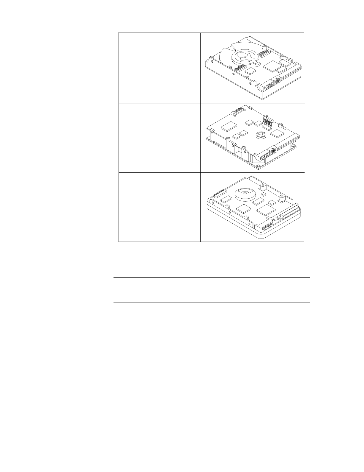
Step 2: Determine the Drive Ty pe
The type of the drive varies and drives with the same part number may be of
different types.
•
Match t he drive you unpacked with the type of drive shown in Figure 1-1.
3
Page 8
Chapter 1 Prepare Drive for Installation
Type 1
P1213A 9.10 GB Model
P1214A 9.10 GB Model
P1215A 18.2 GB Model
P1167A 18.2 G B Model
P1169A 36.4 G B Model
Type 2
P1213A 9.10 GB Model
P1214A 9.10 GB Model
P1215A 18.2 GB Model
P1167A 18.2 GB Model
P1169A 36.4 GB Model
Type 3
P1213A 9.10 GB Model
P1214A 9.10 GB Model
P1215A 18.2 GB Model
P1167A 18.2 GB Model
P1169A 36.4 GB Model
Figure 1-1. Identification of the Three Different Types of Dri ves
NOTE Some of the product numbers are duplicated, because the type
of drive shipped is not always the same. Therefore, it is
important that you match your drive to the correct type.
The types of drives differ in that the jumpers are in different locations. Refer to
the appropriate illustration (Figure 1-2, 1-3, or 1-4) for your type of drive, and
note the location of the jumpers.
4
Page 9
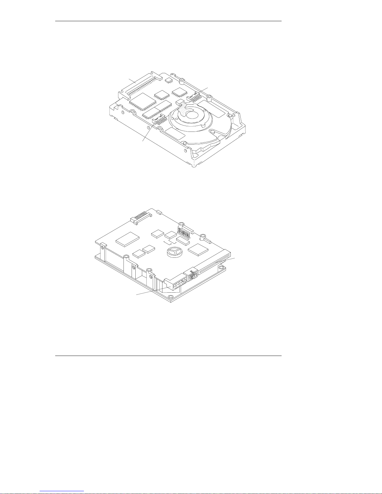
Chapter 1 Prepare Drive for Installation
J6
The "Disk Drive Characteristics" appendix shows a legend of the drive control
settings and the jumper control settings for the individual drives.
SCSI
Connector
J4
Figure 1-2. Component Identification, Type 1 Drives
J6
1
15
Power
Connector
J2
1
SCSI
Connector
Figure 1-3. Component Identification, Type 2 Drives
5
Page 10
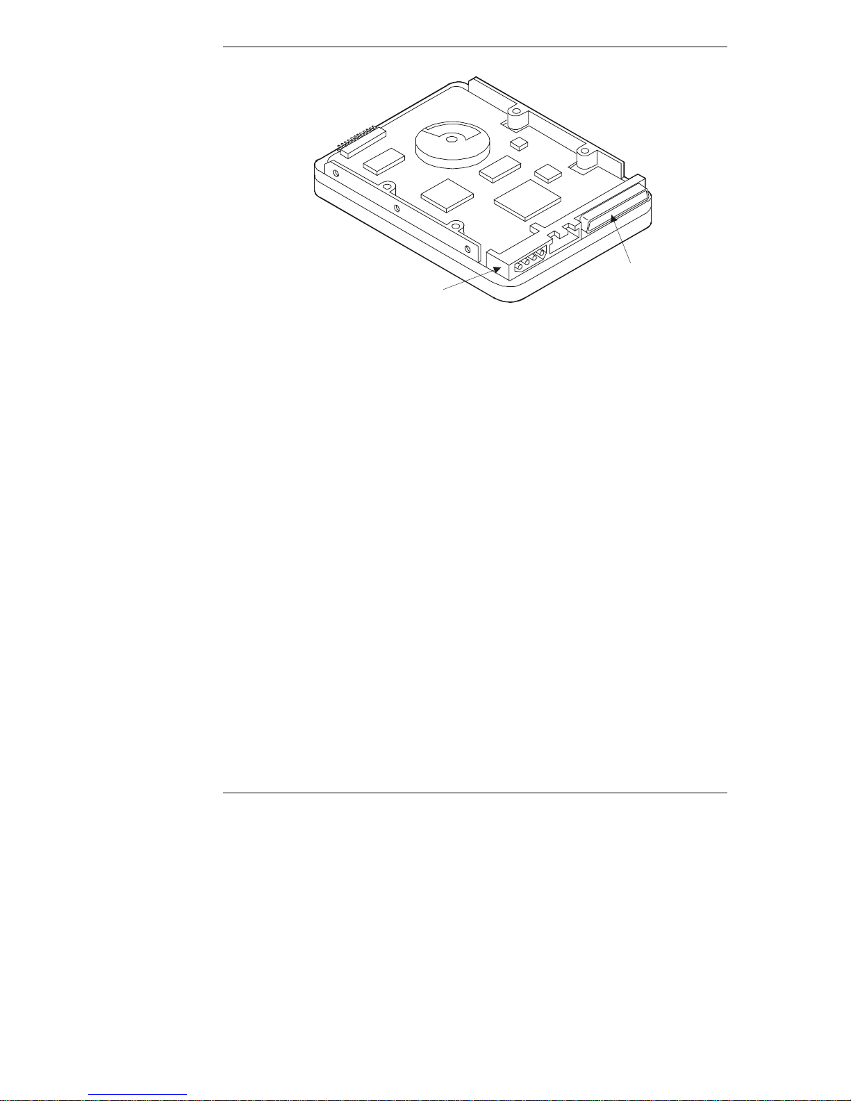
Chapter 1 Prepare Drive for Installation
CN2N2
SCSI
Power
Connector
Figure 1-4. Component Identification, Type 3 Drives
Connector
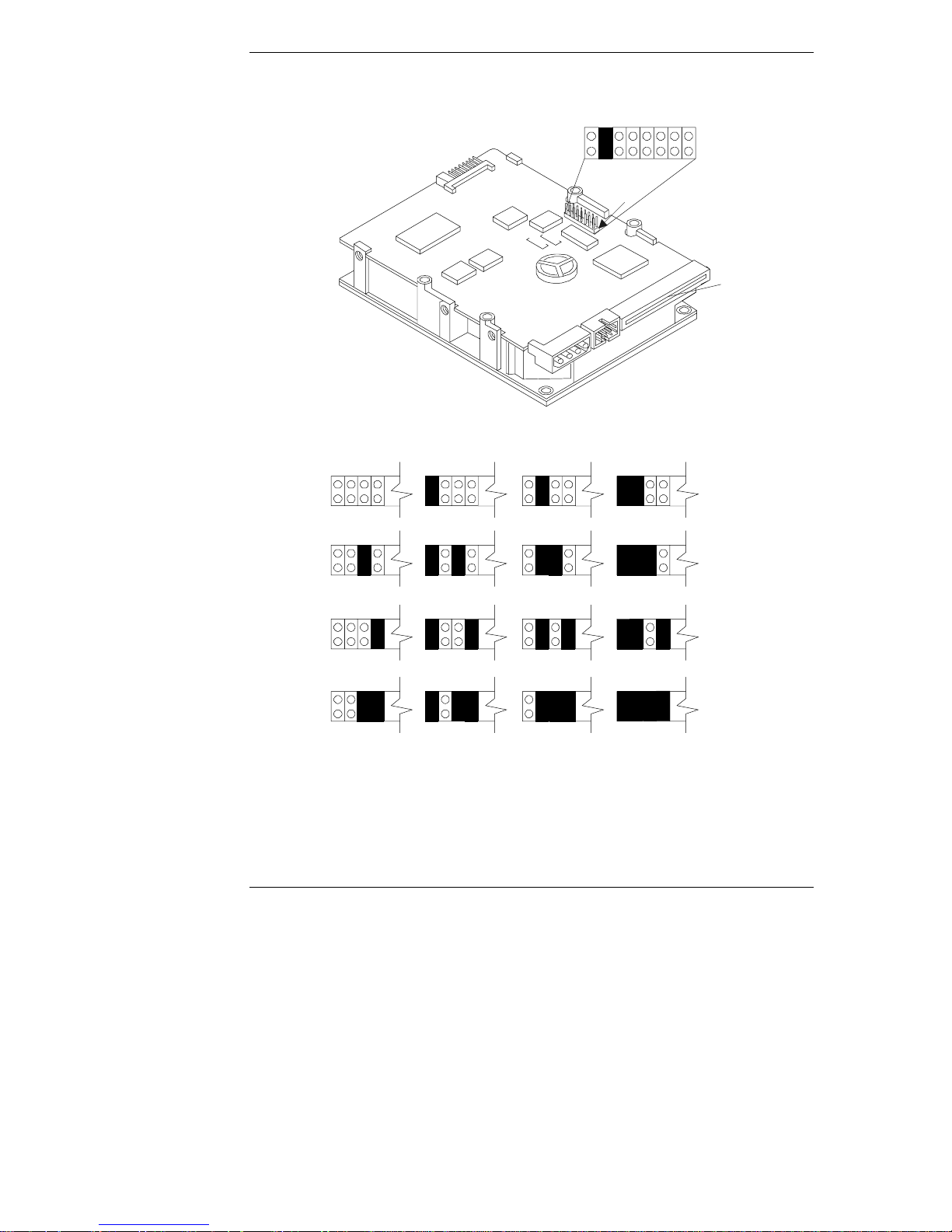
Step 3: Set the SCSI A ddress
The SCSI address is set using jumpers located on the drive. SCSI addresses range
from 0 to 15.
• Each drive is preset to SCSI address 3.
• Address 7 is reserved for communications with the SCSI host bus adapter.
Set the drive to the lowest available SCSI address. Address 0 should be used for
the first drive in the system. Typically, address 1 is assigned to the second hard
disk drive, address 2 is assigned to the third drive, and so forth.
This step assumes the jumpers are accessible. If they are not accessible, it may be
necessary to remove the mounting tray or bracket to adjust the settings.
Each device on the channel needs a different SCSI address. If this is the first
hard drive in the system, complete this step to verify the jumper is set correctly. If
this is one of two or more SCSI devices in the system (and not the first drive),
you must change the SCSI address for the drive.
•
If you are connecting an Ultra3 SCSI drive to a narrow SCSI cable
narrow SCSI controll er, set the SCSI addr ess to 0, 1 , 2, or 3.
•
If you are connecting an Ultra3 SCSI drive to a wide SCSI cable and wide
SCSI controller, set the SCSI address to 0, 1, 2, 3, 4, 5, or 6.
Detailed descriptions of all the jumpers are provided in the "Jumper Settings"
appendix. Figures 1-7, 1-8, 1-9, 1-10 a nd 1-11 show the default SCSI address
settings for each drive.
1
When connecting to a HP NetServer E45, a 68-50 pin adapter will also be needed.
6
1
and
Page 11
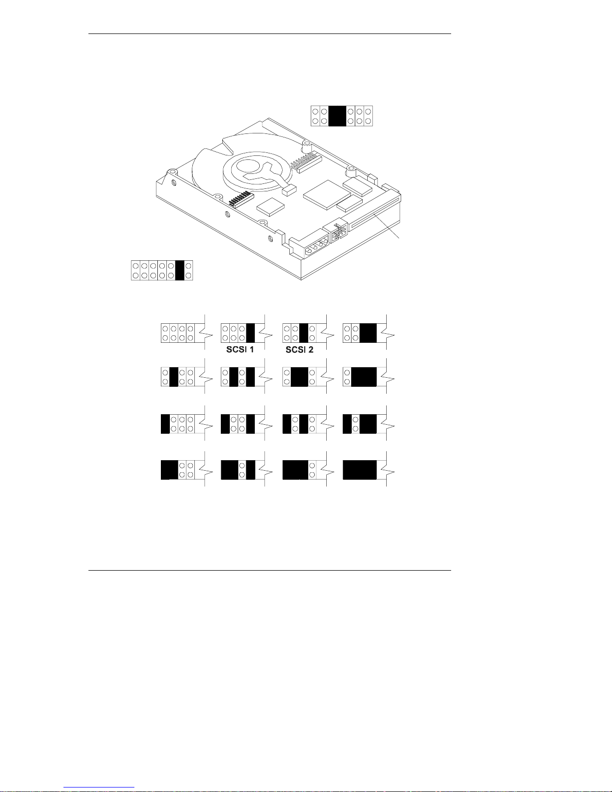
Chapter 1 Prepare Drive for Installation
SCSI 3
SCSI 11
SCSI 15
R R L
A A A A E E E
3 2 1 0 S S D
J4
17
J4
7
1
J6
G
A
R R R R
E E E P E D M
S S S D S S E
J6
A
G
68-Pin SCSI
Connector
J4
1
SCSI 0
SCSI 4
SCSI 8
SCSI 12
SCSI 5
SCSI 9
SCSI 13
SCSI 6 SCSI 7
SCSI 10
SCSI 14
Figure 1-5. SCSI Address Sett i ngs, Type 1 Drives
7
Page 12
Chapter 1 Prepare Drive for Installation
J2
SCSI 14
R R
S D M W P E E T
J2
E S E P D S S P
1
J6
SCSI 0
SCSI 4
J6
SCSI 1
SCSI 5
15
1
15
SCSI 2 SCSI 3
1
1
68-Pin SCSI
Connector
SCSI 7SCSI 6
SCSI 8 SCSI 9 SCSI 10 SCSI 11
SCSI 12
SCSI 13
SCSI 15
Figure 1-6. SCSI Address Sett i ngs, Type 2 Drives
8
Page 13

Chapter 1 Prepare Drive for Installation
SCSI 2
SCSI 3
SCSI 6
SCSI 7
SCSI 10
SCSI 11
SCSI 14
SCSI 15
R L R R N R
E E E E S / D E A A A A
CN2
S D S S E WS S 3 2 1 0
1
1
CN2N2
68-Pin SCSI
Connector
CN2
1
SCSI 0 SCSI 1
SCSI 4
SCSI 8
SCSI 12 SCSI 13
SCSI 5
SCSI 9
Figure 1-7. SCSI Address Sett i ngs, Type 3 Drives
9
Page 14

Chapter 1 Prepare Drive for Installation
Step 4: Connect SCSI Cable A dapter (if required)
The SCSI cable adapter, HP part number 5182-4551 (see Figure 1-8), allows you
to connect an Ultra3 SCSI drive to a narrow SCSI cable and narrow SCSI
controller (9.10 GB only). If you are not connecting your dr ive to a nar row cable,
continue with Step 5.
Ultra3 SCSI
Connector
Narrow SCSI
Connector
Figure 1-8. Narrow to Ultra/Wide SCSI Adapter
•
Plug the narrow SCSI cable into the adapter, aligning the notch in the
connector with the slot in the adapter.
•
Plug the other end of the adapter into the drive. The shape of the
connector prevents it from being plugged into the drive incorrectly.
Step 5: Continue Installation
If you are installing the drive in an HP NetServer L Series, continue with
Chapter 2. If you are installing the drive in an HP NetServer E 45 or E 50,
continue with Chapter 3. If you are installing the drive in an HP NetServer E 60,
refer to the HP NetServer E 60 Installation Guide.
10
Page 15

2 Mount the Drive in the NetServer
L Series
This chapter describes the installation of a drive in the NetServer L Series.
Step 1: Mount the Drive in the System
Use the tray with the drive activity light for mounting a drive in the front of a
NetServer. The drives are shipped already mounted on this tray. To purchase the
tray separately, order Product Number D2198B (multipack).
Figure 2-1. Tray
Consult Information Assistant on the HP NetServer Navigator CD-ROM for your
system for additional information regarding the tray or bracket.
Attach a tray to a drive or change a factory-supplied tray (if needed) as follows:
•
Place the drive on a flat surface, free of static electricity, with the circuit
board of the dr ive facin g u p .
•
If your drive is on a tray that is not appropriate for your server, remove the
four screws attaching the drive to the tray and remove the tray. These
screws can be used to mount the drive on the tray or bracket.
•
Place the new tray or bracket on the drive.
•
Align the mounting holes on the tray or bracket with those on the drive.
•
Attach the tray or bracket to the drive using the four screws.
11
Page 16

Chapter 2 Mount the Drive in the NetServer L Series
Step 2: Connect the Drive Activity Light
The mounting t ray (D2198B) has a dr ive activity light on the front-panel. The
drive activity light flashes during data access and the drive power-on self-test.
Connect the drive activity light for your drive as shown in Figures 2-2, 2-3, a nd
2-4.
1
7
J4
L
E
D
J4
12
+5V Red Cable
17
Black Cable
Driv e Ac tiv ity LE D
Figure 2-2. Activity Light Connection, Type 1 Drives
Page 17

Chapter 2 Mount the Drive in the NetServer L Series
1J6J2
R R
L
E
D
+5V Red Cable
Black C ab le
Drive A ctiv ity LED
CN2
+5V Red C ab le
Black Cable
Drive Activity LED
1
S D M W P E E T
E S E P D S S P
15
1
15
J2
Figure 2-3. Activity Light Connection, Type 2 Drives
R L R R N R
E E E E S / D E A A A A
S D S S E WS S 3 2 1 0
1
1
CN2N2
1
Figure 2-4. Activity Light Connection, Type 3 Drives
13
Page 18

Chapter 2 Mount the Drive in the NetServer L Series
Step 3: Connect the Drive
In this step, you install the drive in the system, and connect the SCSI data cable
and the drive power ca bl e. Th e SCSI cable i s connect ed to the SC SI connector on
the system board or to a SCSI host bus ada p t er board.
In order to run in LVD mode, the term "LVD" must also appear on the
termination module. (Not all NetServer L Series have LVD 68-pin cables. Some
NetServers have cables with a single-ended (SE) active termination module on
one end of the cable. The SE active termination module is easy to recognize,
because it looks different from the other conn ectors on the cabl e, and the word
"active" should appear on the active termination module.)
NOTE HP Ultra3 SCSI drives must connect to the actively terminated
cable. Using an incorrect cable (or not using an active
termination module) will cause data transmission errors.
Do not use passively terminated cables with Ultra3 SCSI hard
disk drives.
CAUTION The active termination module belongs on the last connector
on the cable, opposite the system board or host bus SCSI
adapter. Do not remove this module.
14
•
Turn off your system and the display.
•
Di s connect the power cords.
•
Detach any external cables.
•
Remove the cover from the HP N e tServer.
•
Remove any hardware necessary to reach the cables or insert the drive.
Consult Information Assistant on the HP NetServer Navigator
CD-ROM for your system for instructions.
•
Insert the mounted hard drive in your HP NetServer.
•
Conn ect the internal power supply cable to the hard di sk dr i ve with one of
the unused cables from the power supply unit.
•
Select an available connector on the SCSI cable and connect it to the disk
drive.
CAUTION The connect or is keyed. Do not force t he conn ector in th e
slot. (The red stripe on th e edge of the cable denotes the
position of Pin 1 on the cable.)
Page 19

Chapter 2 Mount the Drive in the NetServer L Series
•
Record information about the new hard disk setup, including: model
number, capacity, and SCSI address.
•
Reassemble your HP NetServer.
•
Connect all the cables and power cords.
•
Power up your HP NetServer.
NOTE If a drive recognition error displays during system startup,
press Ctrl+Alt+Del to restart the system. Do not power cycle
the system because the drive recognition error will likely
repeat.
Step 4: Configure the Drive
The SCSI controller is configured for the drive using a configuration utility.
•
If the SCSI controller is not yet configured, run the appropriate
configuration utility, included with your system.
•
Consult your operating system documentation for information on
formatting the disk drive for use in the system. Typically, you create one
or more partitions on your new hard drive, using the guidelines in
Appendix B, "Disk Drive Characteristics."
•
Initialize the file system, using the operating system format utility.
CAUTION No low-level format is needed. HP performs the low-level
format at the factory.
NOTE If you are experiencing problems with the drive, watch the
mess ages on your monitor while the system boots. A messag e
appears if a drive is not recognized by the HP NetServer
(which happens when the HP NetServer attempts to
communicate with a drive before the drive has finished
spinning up).
If the system did not recognize a hard drive:
• Wait until all drives reach full speed.
• Press th e Re se t button on th e system or p ress the
Ctrl+Alt + De l hot-key combination to restart the HP
NetServer without powering it down.
Do not power-down (power-cycle) the system to restart it, as
this causes all the drives to stop spinning.
15
Page 20

Page 21

3 Mount the Drive in the NetServer
E 45 or E 50
This chapter provides instructions for installing a hard disk drive in the
HP NetServer E 45 or E 50.
Consider the following when installing a drive in an HP NetServer E Series
system.
• The HP NetServer E 45 supports up to four 9-GB Ultra3 SCSI 7200-RPM
drives.
• Only drive type P1213A is supported in the HP NetServer E 45.
• All Ultra3 SCSI drives are not supported in th e HP NetServer E 40 or the
HP NetServer E 30.
NOTE The HP NetServer E 45 ships with drive mounting trays
installed in shelves 3 and 4. Drives shipped as accessories
usually come installed on a factory tray, which must be
removed. The drive must be put on an HP NetServer E 45 tray
(See Figure 3-2).
Step 1: Determine the Drive Location
The drive can be mounted in one of several possible locations in the system. If
you decide to mount the drive on shelf 5 or 6 (recommended), you will fasten the
drive to the chassis. If you decide to install the drive on shelf 3 or 4, you will
mount the drive onto a tray, which is installed in one of the shelves.
•
Deci d e whether to mount the dr ive on shelf 5 or 6 ( recommended) or on
shelf 3 or 4. See Figure 3-1 for the locations of shelves in the system, and
some of the cabling options.
17
Page 22

Chapter 3 Mount the Drive in the NetServer E 45 or E 50
Power
Switch
FlexibleDisk
Controller
FlexibleDisk
CD-ROM
SystemBoard
IDE1
IDE2
F5
D5
Shelf 1
Shelf 2
Shelf 3
Shelf 4
For cabling options and connector locations, see the
Technical Reference Label inside your HP NetServer chassis.
*
C33
SCSICard
PCI 1
Shelf 5
Shelf 6
Key
AvailableConnector
EngagedConnector
C33
50-pin SCSI Cable
D5
IDE CD-ROM Cable
FlexibleDisk Cable
F5
Built-inSCSI Terminator
*
Figure 3-1. NetServer E 45 Shelf Posi t i ons and Cabl ing Options
•
Use the guidelines in Table 3-1 to determine the proper location within
your HP NetServer E 45 to install your hard disk drive.
Table 3-1. M ass St or age Devi ce Locat i ons and SCSI I D Set t i ngs
Device Location SCSI Add ress
Standard Hard Drive
She lf 5 0 (d efault)
(in models that
include one)
18
HP Accessory 9 GB
HD (P1213A)
Shelf 3, 4, 5
or 6
0, if it is the first hard drive; for
subsequent dr i ves, use address 1, 2
or 3
HP SureStore T4i Shelf 3 or 4 4 (default)
HP SureStore 8i,
5000i, 2000i
Stand a rd SCSI
Shelf 3 or 4 2 (default)
(can be set to any unused address)
PCI 1 Slot 7
Controller
•
If the drive is in a factory-provided tray, place the drive on a flat surface
free from static electricity with the circuit board on the drive facing up.
Remove the four screws that attach the drive to the tray and remove the
drive. (These screws can be used to mount the drive in the HP NetServer
E 45.)
Page 23

Chapter 3 Mount the Drive in the NetServer E 45 or E 50
Step 2: Mount the Drive in the System
To prepare to install the drive:
•
Turn off your system and the display.
•
Di s connect the power cords.
•
Detach any external cables.
•
Remove the cover from the HP N e tServer.
•
Remove any hardware necessary to reach the cables or insert the drive.
Consult Information Assistant on the HP NetServer Navigator CD-ROM
for your system for specific instructions for removing components.
If you are mounting the drive in shelf 5 or 6, continue with "Mount the Drive in
Shelf 5 or 6" If you are mounting th e dr i ve in shelf 3 or 4, contin ue with "Mount
the Drive in Shelf 3 or 4."
Mount the D rive in Sh elf 5 or 6
•
Remove the rear-cooling fan. Confirm that the fan is operational. Replace
it if necessary.
•
Align the four screw holes of the rear shelf with the four screw holes of
the drive.
•
Loosely install all of the screws (provided with the drive), then tighten the
screws to no more than eight inch-pounds (0.9 Newton meters).
•
Carefully insert the fan wire fully into the drive bay.
•
Replace the rear cooling fan.
Continue with Step 3.
Mount the D rive in Sh elf 3 or 4
•
Remove the dri ve mounting t ray from the system. (See Figure 3-2.)
Figure 3-2. E 45 Hard Di sk Dr ive Mounting Tr ay
19
Page 24

Chapter 3 Mount the Drive in the NetServer E 45 or E 50
•
Align th e four screw holes in the bottom of the NetServer E 45 tray with
the four screw holes in the bottom of the drive.
•
Loosely install all of the screws, then tighten the screws to no more than
eight inch-pounds (0. 9 Newton-meter).
•
Place the tray in the shelf opening and slide the tray into the shelf.
•
Align the screw holes at the front of the tray with the holes in the front of
the chassis.
•
Loosely install all screws, then tighten each screw to no more than eight
inch-pounds (0.9 Newton-meter).
Step 3: Connect the Drive
Connect the SCSI data cable and power cable and complete the drive installation.
The S C S I cable is con nected t o t he SCSI connect or on the SCSI host bus ad apter
board. (If you are using a na rrow 50-pin cable (part number 5182-4551) when
connecting to a HP NetServer E45, a 68-50 pin adapter will also be needed.)
The correct cable for the E 45 or E50 must have an active termination module on
one end of the cable. The active termination module is easy to recognize, because
it l ooks d ifferent from t he other connectors on th e cable. The cable bundled wi th
your system is actively terminated, and is singled ended.
20
NOTE HP Ultra3 SCSI drives must connect to the actively terminated
cable. Using an incorrect cable (or not using an active
termination module) will cause data transmission errors. Do
not use passively terminated cables with Ultra3 SCSI hard
disk drives.
CAUTION The active termination module belongs on the last connector
on the cable. Do not remove this terminator.
•
Conn ect the internal power supply cable to the hard di sk dr i ve with one of
the unused cables from the power supply unit.
•
Select an available connector on the SCSI cable and connect it to the disk
drive.
CAUTION The connect or is keyed. Do not force t he conn ector in th e
slot. (The red stripe on th e edge of the cable denotes the
position of Pin 1 on the cable.)
Page 25

Chapter 3 Mount the Drive in the NetServer E 45 or E 50
•
Record information about the new hard disk setup, including: model
number, capacity, and SCSI.
•
Reassemble the HP NetServer.
•
Connect all the cables and power cords.
•
Turn on power to the HP NetServer.
Step 4: Configure the Drive
Configure the SCSI controller for the drive using the SCSI SelectTM utility.
•
If the SCSI controller is not yet configured, run the SCSI Select utility,
included with your system.
•
Consult your operating system documentation for information on how best
to format the disk drive for this HP NetServer. Typically, you create one
or more partitions on your new hard drive, using the guidelines in
Appendix B, "Disk Drive Characteristics."
CAUTION No low level format is needed. HP performs the low-level
format at the factory.
•
Initialize the file system, using the operating system format utility.
NOTE If you are experiencing problems with the drive, watch the
mess ages on your monitor while the system boots. A messag e
appears if a drive is not recognized by the HP NetServer
(which happens when the HP NetServer attempts to
communicate with a drive before the drive has finished
spinning up).
If the system did not recognize a hard drive:
• Wait until all drives reach full speed.
• Press the Reset button on th e system or press the
Ctrl+Alt + De l hot-key combination to restart the
HP NetServer without powering it down.
Do not power-down (power-cycle) the system to restart it, as
this causes all the drives to stop spinning.
21
Page 26

Page 27

A Jumper Settings
The hard disk drives are shipped without SCSI terminators. These drives are
ready to use on a SCSI cable with a built-in active terminator.
Each hard disk drive is configured at the factory for optimum performance on
most systems. With the possible exception of setting the SCSI address, you
should not change default settings. Changing the disk drive configuration can
cause unexpect ed or und es i rable results.
Jumper Legend
Table A-1 shows the jumper descriptions for all drives. All jumper-controlled
features are not available on all drives. (An * indicates a factory default setting.)
Table A-1. General Jumper Description
ID
Ax SCSI Addresses (A0, A1, A2 and A3)
LED Light Emitting Diode Drive Activity Light
DS Delay Spin-Up
ME Motor Start Enable
Description
See th e " Set the S C S I A d d ress" st ep in the cha pter " Prepare
Drive for Installation" for detailed information.
Not a jumper in the traditional sense. This is where the drive
activity light connects to the drive.
On* Motor start up is delayed by the sum of the SCSI ID times 6
seconds after power is applied; i.e., Drives 0 and 8 spindles
start immediately, drives 1 and 9 start after a 6 second delay,
drives 2 and 10 start after a 12 second delay, and so forth.
Off Motor start up begins immediately after system power up,
unless Motor Start Enable is on. If Motor Start Enable is on, it
overrides this setting.
On Drive spindle starts when the Start Unit command is received
from the host system. If the Delay Spin-Up feature is on, the
Delay Spin-Up feature is overridden.
23
Page 28

Appendix A Jumper Settings
ID Description
Off* Spindle starts immediately after power up. If Delay Spin-Up
is on, it overrides this setting.
PD Parity Disa bl e
On Parity checking and parity error reporting by the drive is
disabled.
Off* Parity checking and parity error reporting by the drive is
enabled. The drive checks for parity and reports the results of
parity checking to the host system.
RES Reserved
This pin set is not used and must remain as set at the factory.
SE Force Single-ended
On Forces Ultra/single-ended operation.
Off* Drive and controller (and terminator) determines whether to
operate as Ultra3, Ultra2, or Ultra.
WP Write Protect
On The drive is write protected.
24
Off* The drive is not write protected.
* Default
NOTE Jumpers are "off," when the jumper is not installed (no
electrical connection) or "on," when the jumper is in place
(compl et ing the electrical connection).
Page 29

B Disk Drive Characteristics
The proper settings for the following items depend on the operating system
(NetWare, MS-DOS, OS/ 2, Wi ndows NT, UNIX, Banyan Vines, Windows 2000,
or Linux) and corresponding version n um ber:
• Extended Translation setting for the controller
• Partitions, logical drives or divisions for the hot swap hard disk drive
For non-UNIX systems, partition and logical hot swap hard disk drive sizes also
depend on:
• Partition type (Bootable or Non-bootable)
• File system (FAT, HPFS or NTFS)
To determine the appropriate controller and disk drive configuration, consult the
SPU section for your operating system.
25
Page 30

Page 31

C Returning HP Hard Disk Drives
When returni ng a d rive for service, repair, or repla cement, use the packagin g
supplied with the exchange drive.
Foam
Antistatic Bag
Hard Disk Drive
Figure C-1. Drive Repackaging
27
Page 32

Page 33

D Warranty and Suppor t
The hardware warranty below applies to components purchased as accessories. If
your component was factory installed as part of an HP NetServer model, refer to
the warranty statement provided with your system documentation.
Hardware Warranty
This HP NetServer accessory is covered by a limited hardware warranty for a
peri od of on e year from receipt by the orig i nal end-user purchaser.
Once installed in an HP NetServer, this accessory may carry the long er of either a
one-year warranty or the remainder of the warranty period for the HP NetServer
in which it is installed.
This accessory may be serviced through expedited part shipment. In this event,
HP will prepay shipping charges, duty, and taxes; provide telephone assistance
on replacement of the component; and pay shipping charges, duty, and taxes for
any part that HP asks to be returned.
The customer may be required to run HP-supplied configuration and diagnostic
programs before a replacement will be dispatched or an on-site visit is
authorized.
Refer to the warranty statement provided with your original HP NetServer system
documentation for the warranty limitations, customer responsibilities, and other
terms and conditions.
HP Repair and Telephone Support
Refer to the HP Warranty and Service/Support Booklet section of your
HP NetServer system documentation for instructions on how to obtain
HP repair and telephone support.
29
Page 34

Page 35

E Regulatory Infor mation
DECLARATION OF CONFO RM IT Y
according to IS O /IEC Guid e 22 and E N 45014
Manufacturer’s Name: Hewlett-Packard Company
Address: 10955 Tantau Avenue
Cupertino, CA 95014
USA
declares, that the product
Product Name: 9-GB, 18-GB, and 36-GB Ultra3 SCSI Disk Drives
Model Number(s): HP P1213A, HP P1214A, HP P1215A, HP P1167A, and HP P1169A
Product Options: N/A
conforms to the following Product Specifications:
Safety: IEC 950:1991 + A1, A2 / EN 60950 (1992) + A1, A2
EMC: CISPR 22:1985 / EN 55022 (1988) - Class B
EN 50082-1:1992 - Generic Immunit y
IEC 801-2:1991, 4 kV CD, 8 kV AD
IEC 801-3:1984, 3V/m
IEC 801-4:1988, 0.5 kV Signal Lin es, 1 kV Power Lines
FCC Title 47 CFR, Part 15
1
Supplementary Information:
The product herewith complies with the requirements of the Low Voltage Directive
73/23/EEC and the EMC Directive 89/336/EEC.
1) This product was tested in a typical configuration with a Hewlett-Packard NetServer
computer and peripher al s.
Cupertino, February, 2000
Quality Manager
North Ame rican Contact: Hewlett-Packard Company Pro duct Regulations Manager/ 3000 H a nover Street/Palo
Alto, CA 94304 (650) 857-1501
European Contact: Your local Hewlett-Packard Sales and Service Office or Hewlett-Packard GmbH, Department
ZQ / Standards Euro pe, Herrenberger Straße 130, D-7030 Böbl inge n (FAX: + 49-7031-143143)
31
Page 36

Page 37

Index
A
active termination, 14, 20
adapter, SCSI cable, 10
D
delay spin-up, 23
Delay Spin-Up, 23
disk drive
configuration, 23
drive
format, 15, 21
logical partition, 15, 21
NetServer tray, 11
product number, 1
drive activity light, 12, 23
D4910A, 12
D4911A, 12, 13
drive style
D4910A, 6
D4911A, 5, 6
F
file system initialization, 15, 21
front mounting tray, 12
H
hardware warranty, 29
HP Information Assistant CD- ROM, 2
HP NetServer Road Map , 2
I
installation
general procedure, 1
NetServer E 45, 17
intern a l power supply cable, 14, 20
J
jumper descriptions, 23
jumper locations
D4910A, 6
D4911A, 5, 6
M
mounted tray, 11
N
narrow SCSI adapter, 10
NetServer E 30, 17
NetServer E 40, 17
NetServer E 45, 17
O
operating system format utility, 15, 21
P
parity, 24
passively terminated
cables, 14, 20
R
restart system, 16, 22
returning a drive, 27
S
SCSI address, 23
default, 6
range, 6
typical settings, 6
SCSI address settings
D4910A, 7
D4911A, 8, 9
SCSI addresses, 2
SCSI cable, 14, 20
SCSI cable adapter, 10
SCSI con nector , 14, 2 0
SCSI controller, 15, 21
SCSI drive power cable, 14, 20
SCSI hard dri ves
multiple, 6
33
Page 38

Index
SCSI host bus adapter, 6 , 14, 20
SCSI Select utility, 15, 21
SCSI terminators, 23
setup information, 2
shock, 3
start unit command, 24
static electricity, 3
support, 29
system board, 14, 20
system boot, 15, 21
T
tools, 2
U
Ultr a Wide SCSI connect or, 10
W
write protect, 24
34
 Loading...