

Page 1

HP AA NetServer
4000 Reference Guide
Printed in March 2000
Page 2

HP NetServer AA
Notice
The information contained in this document is subject to change without notice.
Hewlett-Packard makes no warranty of any kind with regard to this material,
including, but not limited to, the implied warranties of merchantability and fitness for a
particular purpose. Hewlett-Packard shall not be liable for errors contained herein or for
incidental or consequential damages in connection with the furnishing, performance, or use of
this material.
Hewlett-Packard assumes no responsibility for the use or reliability of its software on
equipment that is not furnished by Hewlett-Packard.
This document contains proprietary information that is protected by copyright. All rights are
reserved. No part of this document may be photocopied, reproduced, or translated to another
language without the prior written consent of Hewlett-Packard Company.
Assured Availability is a trademark, and the Marathon logo and Endurance are registered
trademarks of Marathon Technologies Corporation. Microsoft and Windows NT are
registered trademarks of Microsoft Corporation. All other brand or product names are
trademarks or registered trademarks of their respective holders.
Network Server Division
NSD Technical Training
10955 Tantau Avenue, MS45SLF
Cupertino, California 95014 USA
© Copyright 2000, Hewlett-Packard Company.
ii
Hewlett-Packard Company
Page 3

AA 4000 Reference Guide
Contents
CHAPTER ONE ~ARCHITECTURE OVERVIEW AND TERMINOLOGY..........................................1-1
What is HP AA?................................................................................................................................ 1-2
HPAA Components...........................................................................................................................1-3
Software Components ......................................................................................................................1-4
The Logical Server ...........................................................................................................................1-5
Windows NT and Application Licensing...........................................................................................1-8
Division of Labor..............................................................................................................................1-9
The Compute Elements....................................................................................................................1-9
The SSDLs .......................................................................................................................................1-9
The I/O Processors...........................................................................................................................1-9
Client Network Access....................................................................................................................1-10
SCSI Identifiers...............................................................................................................................1-11
SCSI Port Number Changes...........................................................................................................1-12
Device Redirection .........................................................................................................................1-14
Putting it all together......................................................................................................................1-16
NetServer Rackmount Configurations............................................................................................1-18
Rules for maintaining availability ..................................................................................................1-20
CHAPTER TWO ~HPAA SYSTEM BOOT UP........................................................................................ 2-1
Verifying the MIC connections.........................................................................................................2-2
Checking the SSDL LEDs ...............................................................................................................2-2
Troubleshooting a “RED” LED .......................................................................................................2-4
The MTCTEST utility......................................................................................................................2-4
Powering Up the HPAA System........................................................................................................2-7
Cabling the AA 4000 hardware........................................................................................................2-7
Cabling the Console Switch.............................................................................................................2-8
Power Distribution ...........................................................................................................................2-9
Power On Sequence .......................................................................................................................2-10
AA 4000 Boot Options....................................................................................................................2-12
AA 4000 Boot Process....................................................................................................................2-13
IOP Boot ........................................................................................................................................2-13
The First CE Boot ..........................................................................................................................2-13
The Second CE Boot......................................................................................................................2-13
Using the Keyboard, Mouse, and Video .........................................................................................2-15
Video..............................................................................................................................................2-15
Keyboard and Mouse Control........................................................................................................2-16
Shutting Down the System ..............................................................................................................2-18
MTCCONS.exe..............................................................................................................................2-18
Removing Components..................................................................................................................2-19
Server Shutdowns and Reboots......................................................................................................2-21
Avoiding Unnecessary Re-Mirror Operations ...............................................................................2-21
Using the “Right” Copy of Windows NT........................................................................................ 2-22
When to use Windows NT on the IOPs .........................................................................................2-22
When to use Windows NT on the CEs...........................................................................................2-22
CHAPTER THREE ~AA 4000 AND HP MANAGEMENT TOOLS........................................................3-1
AA 4000 Software Architecture ........................................................................................................3-2
Marathon System Manager (MSM) ..................................................................................................3-4
Remote Management ........................................................................................................................3-5
MSM – Main Screen ........................................................................................................................3-6
Control and Display ........................................................................................................................ 3-7
Control and Display Options............................................................................................................3-8
MSM Preferences .............................................................................................................................3-9
Device Status ..................................................................................................................................3-10
Last Mirror Copy Status.................................................................................................................3-12
Network Server Division
iii
Page 4

HP NetServer AA
Utilities........................................................................................................................................... 3-13
Display Software Revisions............................................................................................................ 3-14
HP TopTools Remote Control Card............................................................................................... 3-15
HP TopTools and Agents................................................................................................................3-15
ManageX ........................................................................................................................................ 3-15
CHAPTER FOUR ~NETWORKING EXPLAINED ................................................................................. 4-1
Network Planning............................................................................................................................. 4-2
PCI Slot locations ............................................................................................................................ 4-2
Windows NT Bus Numbering .........................................................................................................4-3
How Windows NT sees it… ............................................................................................................4-3
Gathering Networking Information .................................................................................................4-4
Three Independent Networks............................................................................................................ 4-4
The Private Network (IOP link) .......................................................................................................4-5
IOP Link Configuration ...................................................................................................................4-5
The Public Network (Ethernet Rails) ...............................................................................................4-7
Public Rail Configuration (IOP)...................................................................................................... 4-8
IOP Public Rail Bindings................................................................................................................. 4-9
Public Rail Configuration (CE)........................................................................................................4-9
Virtual Adapters...............................................................................................................................4-9
CE Bindings................................................................................................................................... 4-10
Public Network to IOP to CE and Back......................................................................................... 4-11
The Virtual Network....................................................................................................................... 4-12
Virtual Network Configuration ......................................................................................................4-12
Adding a Public Rail ...................................................................................................................... 4-14
Working with a fully configured system ......................................................................................... 4-14
CHAPTER FIVE ~SYSTEM UPGRADES ............................................................................................... 5-1
Before Upgrading the HP AA System...............................................................................................5-2
Becoming Familiar With the Array .................................................................................................. 5-2
System Documentation ..................................................................................................................... 5-3
Adding Additional Storage to the Array........................................................................................... 5-4
Can downtime be tolerated? ............................................................................................................5-4
Software requirements:....................................................................................................................5-4
Document the present storage configuration....................................................................................5-4
Install the additional storage ............................................................................................................ 5-5
Decision time................................................................................................................................... 5-5
Reboot the IOP ................................................................................................................................5-5
Configuring the new mirrored drive ................................................................................................ 5-5
Determine the 4 digit SCSI Identifier .............................................................................................. 5-6
Modify the Marathon configuration on IOP1 and IOP2.................................................................. 5-7
Reboot the array............................................................................................................................... 5-9
Confirm the new drives on the CE...................................................................................................5-9
Adding SCSI Devices (HBA's, HP NetRAID)................................................................................... 5-9
Upgrading the Marathon Software ................................................................................................ 5-11
Upgrading Marathon software on the CE Operating System......................................................... 5-12
Upgrading Marathon Software on Each IOP ................................................................................. 5-12
Running MTCFlash on each CE....................................................................................................5-13
Verifying the Upgrade ................................................................................................................... 5-14
Upgrading an Installed System to an SMP IOP System................................................................. 5-15
Other Upgrade and Downgrade Options........................................................................................5-15
Updating/Patching Windows NT with Service Packs..................................................................... 5-16
For the CE Operating System ........................................................................................................ 5-16
For the IOP Operating System.......................................................................................................5-16
Updating NT Applications.............................................................................................................. 5-17
CHAPTER SIX ~BACKUP AND RESTORE ........................................................................................... 6-1
Backup topologies and tradeoffs ...................................................................................................... 6-2
Pure Local Backups ......................................................................................................................... 6-2
Semi-Local Backups........................................................................................................................6-3
iv
Hewlett-Packard Company
Page 5

AA 4000 Reference Guide
Network Backups.............................................................................................................................6-4
Configuration Comparisons .............................................................................................................6-5
Backup Confiurguration Setup Notes...............................................................................................6-6
Pure-local backup configuration ......................................................................................................6-6
Semi-local backup configuration .....................................................................................................6-6
Network backup configuration.........................................................................................................6-8
Disaster recovery procedures.........................................................................................................6-11
Part Numbers for Backup Configurations...................................................................................... 6-15
CHAPTER SEVEN ~BASIC TROUBLESHOOTING .............................................................................. 7-1
Overview of Troubleshooting in a HP AA Environment...................................................................7-2
Diagnosing Faults ............................................................................................................................ 7-2
Other MTC Tools.............................................................................................................................7-3
Isolating the Faults........................................................................................................................... 7-4
Analyzing an Event...........................................................................................................................7-6
Correcting the Faults........................................................................................................................7-9
Providing Information to the HP Call Center ................................................................................7-10
The Windows NT "Blue Screen of Death" ...................................................................................... 7-10
Basic Marathon Hardware Replacement .......................................................................................7-11
Replacing the MIC Cable...............................................................................................................7-11
Replacing the TL Cable .................................................................................................................7-11
Replacing the IL Cable...................................................................................................................7-12
Replacing an IOPx.Ethernet Cable.................................................................................................7-12
Replacing a MIC ............................................................................................................................7-13
Replacing an SSDL........................................................................................................................7-14
Replacing an IOP ...........................................................................................................................7-15
Replacing a CE...............................................................................................................................7-17
Replacing a Failed Ethernet Adapter.............................................................................................7-18
Replacing a Failed Mirrored Disk .................................................................................................7-21
Replacing a Failed NetRAID Adapter............................................................................................7-22
Reenabling faulted Components.....................................................................................................7-23
Troubleshooting Tips .....................................................................................................................7-23
Common Problems .........................................................................................................................7-24
Network Server Division
v
Page 6

Page 7

Ch 1: Architecture Overview and Terminology
Chapter One ~ Architecture Overview and Terminology
This chapter contains a brief overview of the HP AA system based
on the Endrance 4000 software from Marathon Technologies.
Topics to be covered include:
• HP AA Components
• Installation Overview
• How the system works
• Storage Architecture, and
• Network Architecture
Network Server Division
1-1
Page 8

HP NetServer AA
What is HP AA?
HP AA is a platform of high-availability solutions offering the
highest levels of system uptime with the lowest total cost of
ownership in the industry. Using HP NetServers, standard Windows
NT, and unmodified "off-the-shelf" applications, every HP
NetServer AA Solution delivers:
• Nonstop processing through failures & repairs
• Continuous data access to storage
• Uninterrupted network connectivity
• Disaster tolerance for multi-site protection
In addition to using HP NetServers, an OEM hardware/software kit
from Marathon Technologies is used to create one logical server
array from four NetServers. The current model of the kit is known
as the Endurance 4000 (AA 4000). Though HP AA is a HP product
sold by HP and supported by HP, the system splash screens,
administrative tools, and product documentation will make several
references to Marathon and more importantly, Endurance 4000.
Knowing the product name AA 4000 is important in order to
maintain and apply the correct software revisions for the array itself
and the firmware of the interconnect cards.
For the remainder of this reference guide, when referring to the array
as a whole, the convention used is HPAA. When referring to the
specifics of the components, ‘AA 4000’ may be used to distinguish
the generation of the product (as opposed to future products that may
be referred to as ‘E6XX’).
1-2
Hewlett-Packard Company
Page 9
HPAA Components
Ch 1: Architecture Overview and Terminology
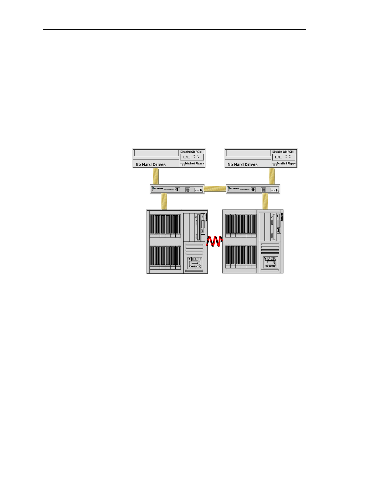
There are four major hardware componenets of the HPAA system:
• The NetServers – Four NetServers are needed, two perform a
synchronous operation of the NT operating system and the other
two perform asynchronous I/O operations.
• Marathon Interface Cards (MIC) – Each NetServer has a MIC
placed in a particular PCI slot. The MICs are identical and all of
them must have the same firmware revision levels.
Network Server Division
• SplitSite Data Link (SSDL) – There are two SSDLs that
provide for the interconnection between the four NetServers. The
SSDLs are simply a transport mechanism between theNetServers
and offer little software control of the system. The SSDLs are
also used to provide video, keyboard, and mouse functions to the
administrator of the system. More information on the SSDLs
will be provided later.
• MIC Cables – Each MIC attaches to the SSDL through the
implementaiton of a 100 pin serial cable. There are two different
MIC cables. The four NetServers attach to the SSDL with an
indentical 5-meter cable. The SSDLs attach to each other with a
similar, but unique cable. This cable is identified as the one
cable in the kit that has a ferrite (thicker, black rectangle shape)
incorporated at one end of the cable.
1-3
Page 10

HP NetServer AA
Software Components
Though at first glance, the HPAA solution appears to be mostly a
hardware solution, in fact, it is an “85%” software solution. There
are two major components of the software: the firmware on the MICs
and the AA 4000 software installed on each of the NetServers. This
obviously does not count the Windows NT operating system and any
application software to be added for operation. The Windows NT
software is fairly standard in all implementations; the application
environment will vary among the different implementations.
MIC Firmware
The MIC firmware has a revision level, as do some of its
subcomponents. When the NetServer is booted and going through its
normal boot routine, following POST operations the NetServer will
detect the presence of the MIC. When the MIC is detected the
screen will display the following revision levels:
• Marathon BIOS
• Ucode
• FPGA
• Adpater Revision
The revision levels of each of these components must be identical on
all four NetServers. If one of the NetServers contains a MIC with
down level revisions, then the MIC must be flashed using the
MTCflash utility. Specific steps for performing this operation can be
found in Chapter 6 of the E 4000 User Guide provided with the
system (and provided in Adobe Acrobat format on the AA 4000
CD), or Chapter 6 of this guide.
AA 4000 Software
The HPAA system is shipped to the customer as a complete,
operational array. This includes the AA 4000 software already
installed. The AA 4000 software can also be found on the Marathon
CD provided with the system. It may be necessary during
maintenance procedures to re-install the software (details on this
operation is found in Chapter 6 of this guide). The AA 4000
software exists on the same logical drive where the Windows NT
system files are located for all four NetServers. Some of the files are
in a new directory and some are in the Windows NT system
directory. The specific locations of the AA 4000 software are not as
important as the presence of the software itself.
1-4
CAUTION
The specific files of the AA 4000 software do not need to
be modified or accessed by the administrator through
Windows Explorer. Maintenance of these files must take
Hewlett-Packard Company
Page 11
The Logical Server
Ch 1: Architecture Overview and Terminology
place only through AA 4000 Management Tools or
Utilities.
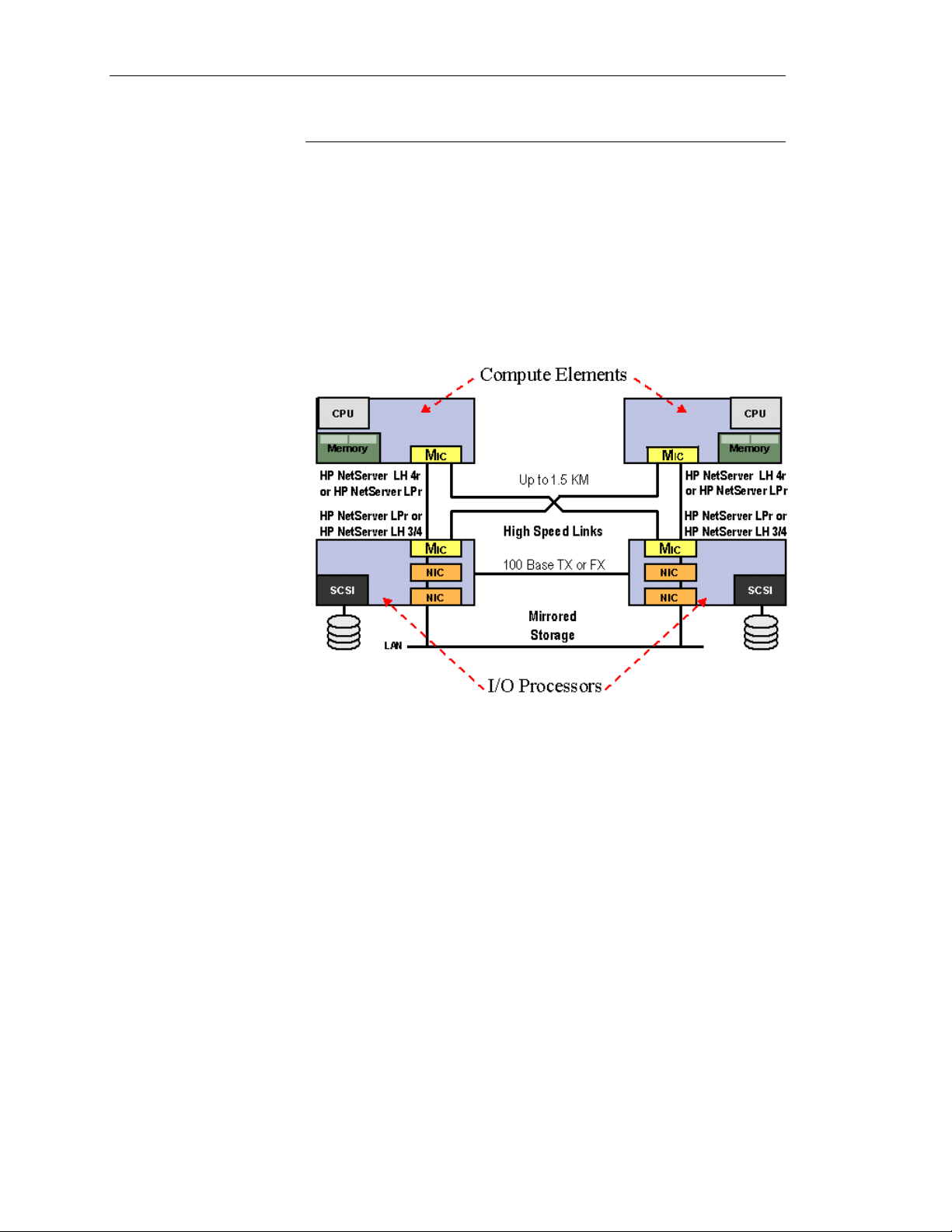
Logical servers are created from an array of four separate servers.
Computing is distinctly separate from the input/output (I/O)
processing, and the array runs simultaneously on two symmetrical
halves (or tuples), which, combined together, do not have a single
point of failure. I/O processors run asynchronously, and the compute
elements run synchronously in lockstep.
Network Server Division
Compute Elements
Two of the NetServers take the roles of Compute Elements (CE’s).
Within the AA 4000 software the CEs are numbered CE1 and CE2.
The CEs are two exactly identical NetServers including the same
stepping code of the same processor type, and the same system
memory sizes. All other components of the CEs are either disabled
in the BIOS or removed from the system. There will be no use of
any onboard SCSI or a SCSI HBA. There are no network cards,
keyboard, mouse, or any other peripheral devices. The lone
exception to this is the MIC. The MIC is the only I/O device in the
CE. These characteristics of the CEs will result in two servers that
can now perform processing in what is called “lockstep.”
With the CEs running in lockstep, together they are running one on
copy of Windows NT Server. During a typical HPAA boot process,
one CE will boot off of a system disk located in one of the servers
functioning as an I/O Processor. The second CE will not boot from a
disk, but instead, it synchronizes with the other CE. Once
synchronization is complete, then the two CEs process in “lockstep”
1-5
Page 12
HP NetServer AA
allowing for the fail through performance should anything happen to
one of the CEs.
I/O Processors
The other two NetServers take the roles of I/O Processors (IOPs).
Within the AA 4000 software the IOPs are numbered IOP1 and
IOP2. An IOP performs all I/O operations on behalf of the CE. It
contains the hard disk drives necessary for storing its own copy of
Windows NT, the CE’s copy of Windows NT, the applications
installed on the CEs (applications for the array), and all of the needed
data. It also has all of the network cards necessary for client access.
In a PCI slot in the IOP is a MIC. Through the SSDLs, the IOP’s
MIC can communicate with either one of the CEs. Typically it only
communicates with one of the CEs.
It is necessary for the IOPs to boot first before the CEs can boot up.
At least one IOP has to be ready with disks available in order for a
CE to have a disk from which it can boot. When the IOP is
operational, the NT administrative tools only see one logical disk,
the one with its own copy of Windows NT. The rest of the disks
have been “redirected” to the ownership of the CEs (redirection will
be covered later in this chapter).
In effect, what is happening is whenever the CE has an I/O operation
to perform, the AA 4000 software intercepts the I/O request Window
NT has made, passes it to the MIC, the MIC passes it to the MIC in
the IOP, then the IOP executes the I/O. This happens in the IOP as if
the I/O operation originated in the IOP’s copy of Windows NT when
in fact it was “inserted” by the AA 4000 software and MICs. When
the I/O operation is complete, the “results” are sent back through the
MICs to the processor and cache of the CEs.
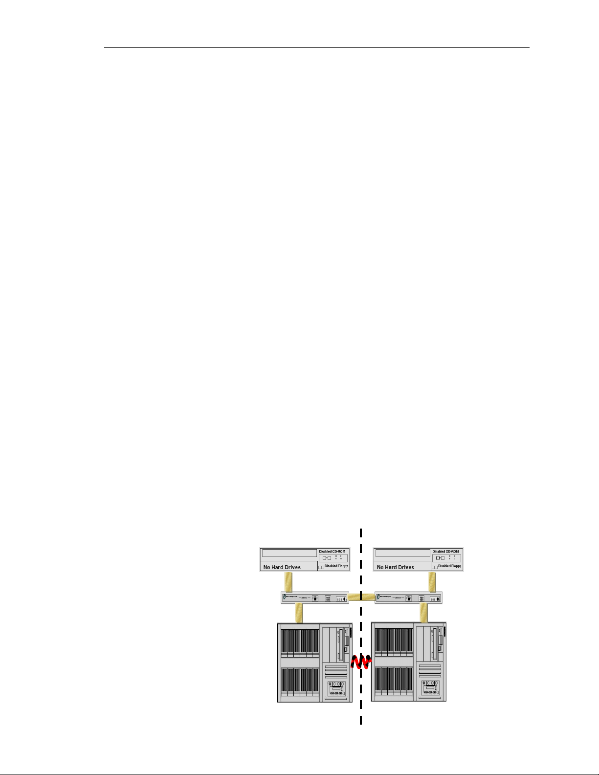
Tuple
1-6
Tuple 1 Tuple 2
Hewlett-Packard Company
Page 13
Ch 1: Architecture Overview and Terminology
The term tuple simply refers to the pair of one
CE and one IOP connected through one SSDL.
Tuples are important during installation and
when trying to determine the status of the array.
By default, CE1 attempts comminucation with
IOP1 first, and then IOP2 in the event of IOP1
being unavailable. However, even though the
CEs try to communicate within their own tuple first, cross-tuple
communications will occur when one of the NetServers is
unavailable.
As long as the MIC cables are attached to the slot correctly on the
SSDLs, the tuples are “predefined.” There is only one way to
configure the tuples, and CE1 and IOP1 will always be tuple 1; the
same is tru for CE2, IOP2, and tuple 2.
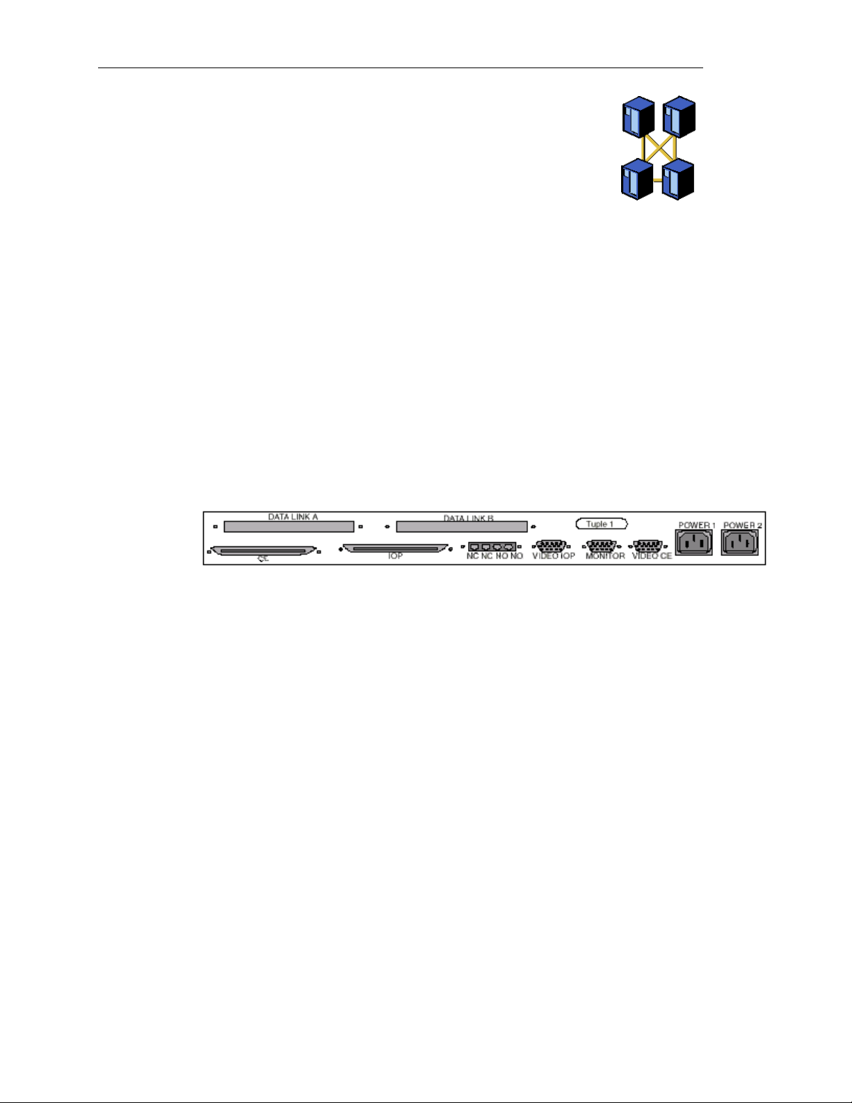
All of the MICs are the same. What distinguishes CE from IOP, and
CE1 from CE2, is the position of the cable on the SSDL and the
SSDL itself. Though the SSDLs are identical in appearance, there is
a slight difference in the inside of the SSDL that distinguishes
between SSDL1 and SSDL2. The following is a rear view of the
SSDL where the MIC cables are plugged.
Note that there are two 100 pin serial ports for the MIC cable, but
there are specifically labeled for CE or IOP. The Data Link A port is
for the Tuple Link cable (similar to the MIC cable) that goes to the
other SSDL.
Network Server Division
1-7
Page 14

HP NetServer AA
Windows NT and Application Licensing
The HPAA based on the AA 4000 software requires four Windows
NT licenses. The CEs must have two licenses of Windows NT
Server or Windows NT Enterprise Edition and the two IOPs must
have two licenses of any of the Windows NT products (technically,
the IOPs will work with Windows NT Workstation). Given these
parameters, it is recommended to have four Windows NT Server
licenses. Windows NT Enterprise Edition is rarely needed since the
HPAA only supports a single CPU and the MS clustering service is
not used. Windows NT Workstation is not recommended for the
IOPs since future upgrades will not support NT workstation.
Windows NT Installations
There are three actual installations of Windows NT, one for each
IOP and one for both CE’s. Because there are four servers each with
its own memory and therefore a copy of the NT Kernel, Microsoft
requires four total NT licenses. Localized language versions of
Windows NT can be installed; however, the AA 4000 software itself
is only available in English and Japanese versions. When installing
the AA 4000 software, Windows NT must have Service Pack 3 or
greater.
Application Licensing
Though the array is comprised of four NetServer each running their
own kernel of Windows NT, the array is only presented as one server
to the network. Clients only have one attachment point at any given
moment. This combined with the fact that the CEs are only running
one copy of Windows NT (in lockstep on two NetServers), means
there is only a need for one application server license per array. For
example, if the HPAA is going to be an MS Exchange Server for the
network, there is only one Exchange Application server license
needed. Client licenses are unaffected. The client license
requirements would be the same as if there was only one physical
server running an application.
1-8
Hewlett-Packard Company
Page 15

Division of Labor
The Compute Elements
Ch 1: Architecture Overview and Terminology
The compute elements and the I/O processors have very distinct
roles and therefore have different performance characteristics. If the
array was going to do nothing more than run Windows NT without
any applications, then the memory requirements are minimal. The
array can be functional with 64 MB of memory for each node. This
serves to prove that the AA 4000 software itself is not memory
intensive and does require a significant amount of server resources.
The compute element functions with just the CPU and the memory.
The server is sized for the maximum amounts of CPU and memory
required for the application that stays within the limits of the
memory support of the physical server and the fact that the HP AA
4000 software currently supports one CPU and a maximum of 2 GB
of system memory. The system will generate I/O requests, but they
are immediately intercepted by the HP AA 4000 software and
transferred to the IOP via the MICs, cables, and SSDLs. This creates
a very low overhead for I/O operations on the CE.
The SSDLs
The I/O Processors
These two components are nothing more than I/O routers. By
requiring that the nodes be attached to specific ports, what little
software function there is in the SSDLs is easily maintained and does
not have to be concerned with any kind of routing scheme or mesh.
The SSDLs are for making sure the data is transferred from each CE
to both IOPs by simply providing a path. The HP AA 4000 software
is responsible for the integrity of the data between the nodes and
largely does this through checksums (EDCs) at the end of each
packet transfer.
Here a different kind of server activity takes place. The I/O
Processors do not run any applications other than simple
management software added by the customer. They are complex I/O
controllers that for lack of an easier solution happen to be running
Windows NT. They are not in lock-step with each other, but instead,
maintain disk synchronization through a HP AA 4000 software disk
partition on each logical disk the CE uses. These are not CPU or
memory intensive operations. As it turns out, the disk activity itself,
as in most optimized server environments, can be the bottleneck if
there is one.
Network Server Division
CAUTION
It is possible to run applications on the IOPs. However, this
impacts the reliability of the overall system. HP strongly
recommends that other applications not be run on the IOPs
but will continue to support the array.
1-9
Page 16
HP NetServer AA
Client Network Access
The HPAA System provides client network access to one logical
server. As a single logical server, the system can provide services
and applications to clients just like any other NT Server. However,
the implementation of the network hardware and software is different
than a single server environment.
The I/O Processors have all of the needed network interface cards
installed for the solution. Two of the network cards provide a private
link between the I/O Processors for disk synchronization and other
activities. Both I/O Processors have an additional network card for
each subnet it provides services and applications. Network cards
must be ordered in pairs so that each IOP can continue to provide
access to each subnet. The two I/O Processors will each go to the
same subnet for client access using a softset MAC address from one
of the cards. The network cards pass all network traffic to the
Compute Elements. The CE’s will then decide what action, if any,
needs to be taken as a result of the network packet. When network
traffic is outbound from the array, only one network card of the pair
will actually place data on the wire so as to avoid Ethernet collisions.
1-10
Hewlett-Packard Company
Page 17
SCSI Identifiers
Ch 1: Architecture Overview and Terminology
During the installation and maintenance of the HPAA system, there
are several different pieces of configuration data that must be
collected, documented, and referenced. One of the more important
pieces is the SCSI identifier for the logical drives that the AA 4000
software will “redirect” to the ownership of the CE.
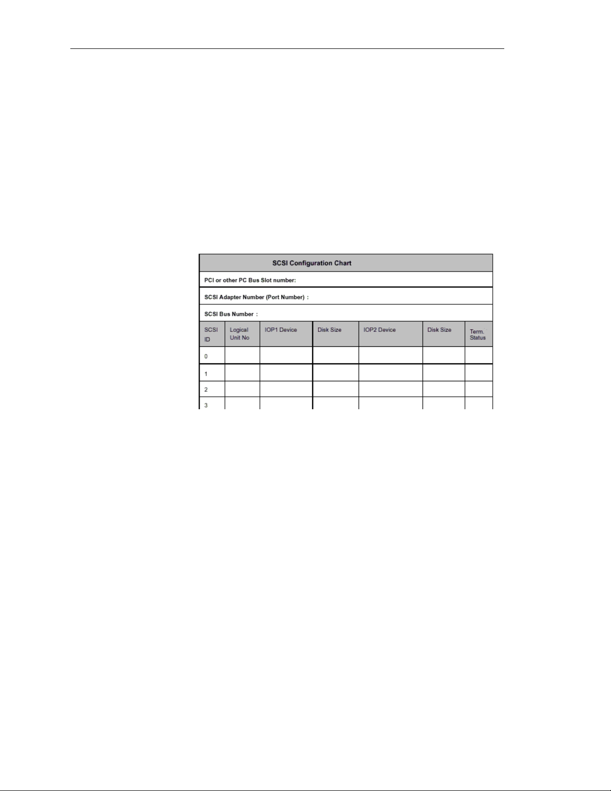
In the AA 4000 Installation Guide bundled with the system (also an
Adobe Acrobat file on the AA 4000 CD), there are several blank
charts for recording SCSI device information. This chart should be
filled out, or a similar one made. The chart helps the administrator
keep track of the SCSI configurations for each SCSI device. An
example of the chart is below.
If the SCSI information for the SCSI devices in the array is not
known, check the Windows NT Registry. The Registry contains an
entry for each SCSI device. Before looking for the SCSI
information, be sure to know which adapter is being used and the
driver name associated with that adapter.
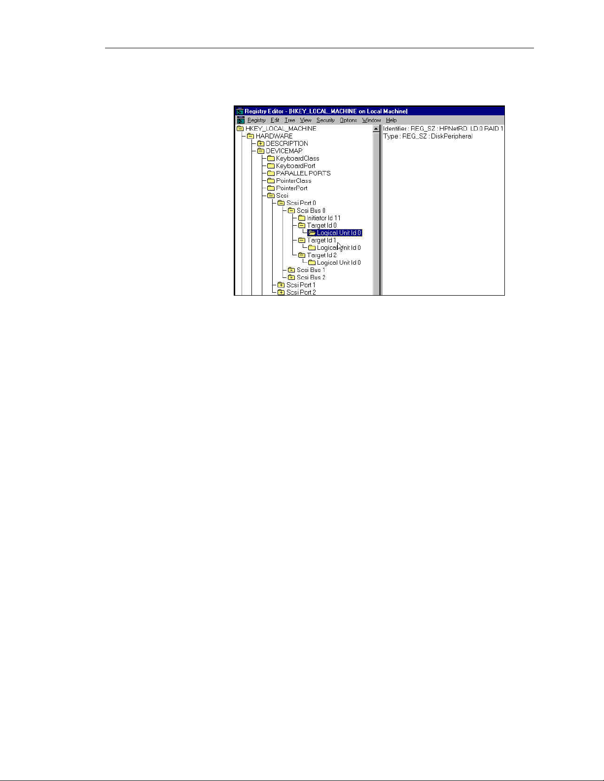
To check the Registry:
1. Open the Windows NT Registry.
2. Choose HKEY_LOCAL_MACHINE\HARDWARE\DEVICEMAP\Scsi
3. Choose the SCSI port matching the adapter.
(Make sure the Driver parameters on the right side of the
Registry window match the adapter being checked.)
4. Choose \Scsi BUS x\Target ID x\Logical Unit Number x
5. On the right side of the Registry window, make sure that the
Identifier and Type parameters describe the SCSI devices.
6. Map the following Registry information to the appropriate field
on the SCSI Configuration Chart.
Network Server Division
1-11
Page 18
HP NetServer AA
Here is an example of the SCSI information needed from the
Windows NT Registry:
When filling out the SCSI configuration chart included in the
Installation Guide, the following notes are some reminders about the
configurations of SCSI devices:
• SCSI Bus Numbers – Be sure to have all of the drivers installed
• SCSI IDs – Verify what SCSI ID is being used by the adapter.
• Boot Disks – For the IOP, this should be the disk that is SCSI ID
SCSI Port Number Changes
Windows NT assigns port numbers to SCSI adapters based on the
load order of the adapters’ device drivers at boot time. This is
important because it is possible that the addition of another SCSI
adapter may impact the NT port assignments. For example, the
addition of an Adaptec Controller may result in its port assignment
being 0 and the other SCSI adapters that previously existed would
have their port numbers increased by 1. The result of this scenario is
the AA 4000 software will not be able to identify the devices
correctly based upon its configuration file.
for the SCSI adapters to be used. The check the NT registry for
the bus numbers.
This may be seen in the setup utility of the SCSI adapter as the
“Initiator ID”, or in the NT Registry as the “Target ID.”
Typically the adpater ID is ‘7,’ but it may be changed or
different. The same SCSI ID for the adapter must be used on
both IOPs.
0 on each IOP. For the CE, this should be the first disk
redirected in the AA 4000 software; typically this is SCSI ID 1.
1-12
Hewlett-Packard Company
Page 19

Ch 1: Architecture Overview and Terminology
To prevent this problem from occurring, you must change the default
load order used by Windows NT. Changing the Windows NT
default load order for SCSI adapter drivers requires modification to
the Registry. Each adapter driver has a Registry key located at:
\HKEY_LOCAL_MACHINE\System\CurrentControlSet\Services\%
adapter_driver_name%
(Where %adapter_driver_name% is the name of the SCSI adapter
driver’s Registry key. For example, an Adaptec 2940 driver has a
Registry key name of aic78xx.)
Each SCSI driver’s Registry key name has an associated value
named Tag.TheTag value contains a number that is used to control
the load order of a particular SCSI driver. Smaller Tag values cause
drivers to load before larger Tag values. The Adaptec 1542’s Tag
value can be changed to a value greater than the Adaptec 2940’s Tag
value, which will cause the Adapter 1542 adapter driver to load last,
preventing the port number discrepancy discussed above.
The Tag value controls the load order of different drivers. However,
if one driver operates more than one SCSI adapter, the Tag value is
useless for altering the port number assignment. In this case, it may
be best to change an adapter’s position in the PCI bus with regard to
another adapter. For example, if you have a SCSI adapter in PCI slot
1, and later you add another SCSI adapter to PCI slot 0, and these
adapters are controlled by the same SCSI driver, this may cause the
SCSI adapter in slot 1 to have its SCSI port number assignment
changed by Windows NT from 0 to 1. To prevent this port number
discrepancy from occurring, try swapping the SCSI adapter in slot 1
with the one in slot 0.
If changing the PCI bus position of an adapter has no effect, consider
moving the devices from the original adapter to the newly installed
adapter. You may be able to accomplish this by simply unplugging
the SCSI bus cables from each adapter and swapping them.
However, if it becomes too difficult to move devices from one
adapter to another, you may want to consider reworking your AA
4000 device configuration database.
Network Server Division
1-13
Page 20
HP NetServer AA
Device Redirection
With the disk and network resources existing on the IOPs, but
“owned” and accessed by the CEs, the AA 4000 software has to have
a way to make this happen. The method is called device redirection.
First, let’s start with a list of devices than can be redirected:
• SCSI Disks
• SCSI Tape Drives
• CD-ROMs
• Ethernet Adpaters
• Floppy Disk Drives
• Keyboard and Mouse
• Serial Ports
These devices exist on the IOP, but when the AA 4000 software
loads during the Windows NT boot process, a configuration file is
checked and all devices that have been configured for redirection no
longer are accessible by the IOP. When the CE boots, it will have
access to the redirected devices.
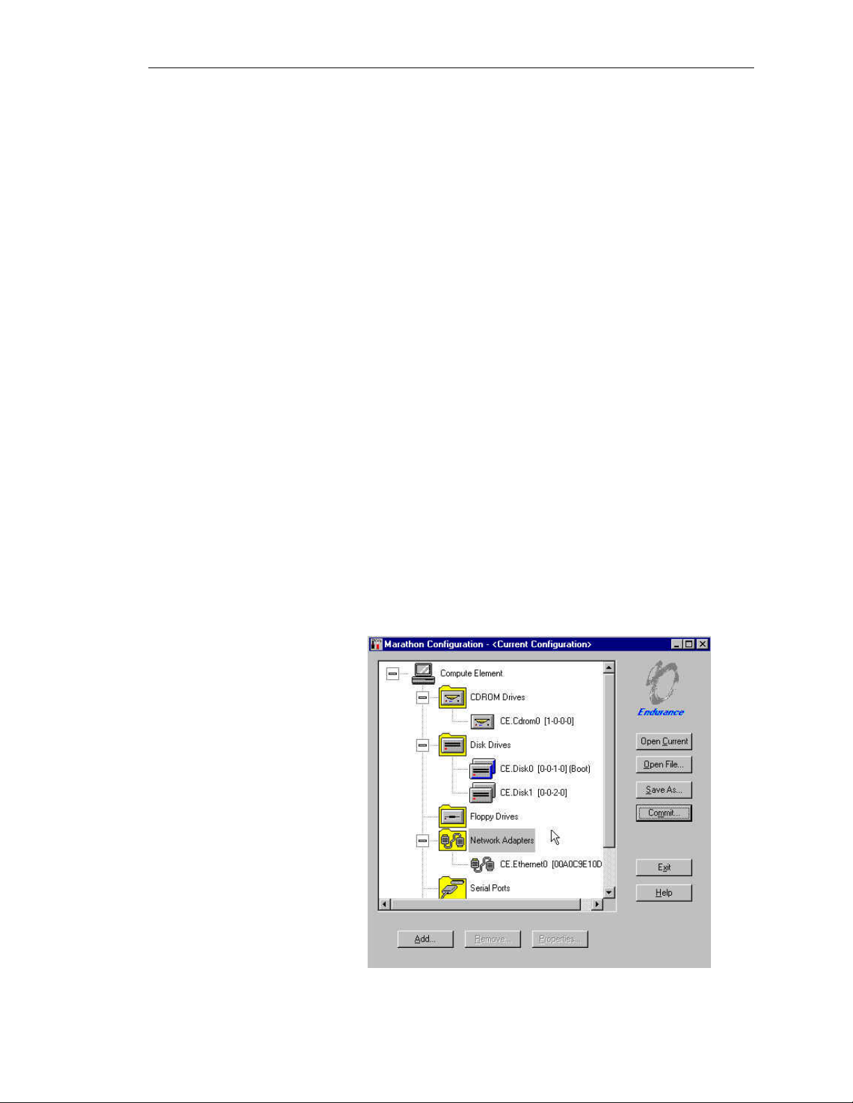
HP AA 4000 Configuration Utility
The list of redirected devices can be found by using the HP AA 4000
Configuration Utility. As seen by the screenshot below, the devices
are redirected by category.
1-14
Hewlett-Packard Company
Page 21

Ch 1: Architecture Overview and Terminology
The keyboard and the mouse connected to the IOPs are automatically
redirected to the CEs when they boot. Control of the keyboard and
mouse can be switched back to the IOP or to the CE by pressing
<CTRL> <SHIFT> <F12>.
The HP AA 4000 Configuration Utility is accessible through the
Start, Program, and HP AA 4000 menus on each of the IOPs. It is
automatically installed as part of the AA 4000 software install.
Whenever a configuration file is changed on one IOP, it must be
committed and the same configuration must exist on the other IOP.
The easiest way to ensure that both configurations are the same is
when one IOP changes, save the results to a floppy diskette and in
the other IOP load the file from the floppy disk and commit the
changes. Configuration changes do not take effect until the next
reboot of the IOPs.
Mirrored Devices
Within the list of devices that can be redirected to the CE, a subset of
that list is mirrored devices. A mirrored device means the device
exists on both IOPs and it is the same resource at all times on both
IOPs. Therefore, if one device shall fail, the other one is still
available and in the necessary state to function as if there was no
failure at all. The best example of this is a disk resource. On each
IOP, a mirrored disk is a disk that exists on each IOP on the same
SCSI bus, with the same SCSI IDs, using the same physical hard
drives, and the same logical disk size. Data is written to each disk on
each IOP asynchronously by the CEs. If one disk should fail, then
the CEs would smply continue to use the remaining disk.
Single Ended Devices
Devices that cannot be mirrored are commonly referred to as
“Single-Ended Devices” in AA 4000 documentation. Do not
confuse this with “Single-Ended SCSI”; they are not the same at all.
An example of a single-ended device is a CD-ROM. The most
important characteristic of a single-ended device is if it fails, the
device must be repaired or replaced. There is not a mirrored device
ready to take over. For example, if the CD-ROM fails on an IOP,
then there will be no access to the CD-ROM until that CD-ROM is
repaired, replaced, or the system is rebooted and the CD-ROM in the
other IOP is redirected. The CD-ROM is not mirrored.
Network Server Division
1-15
Page 22
HP NetServer AA
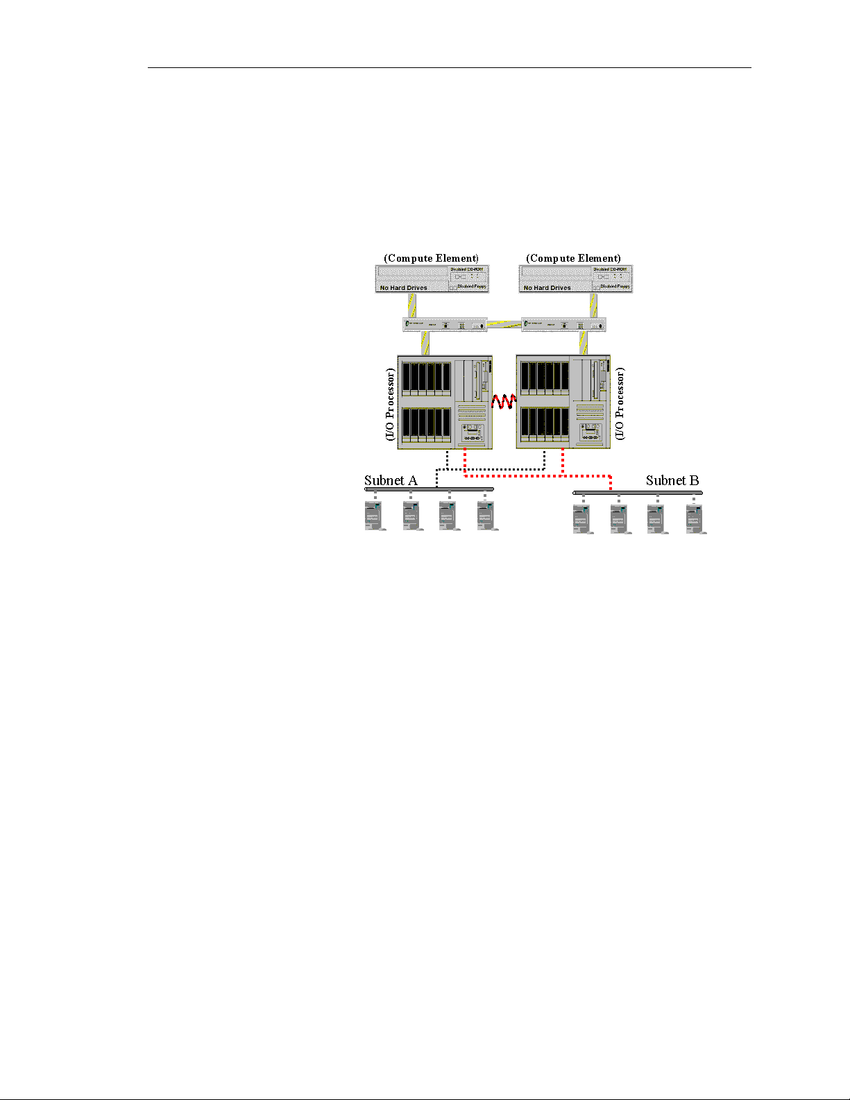
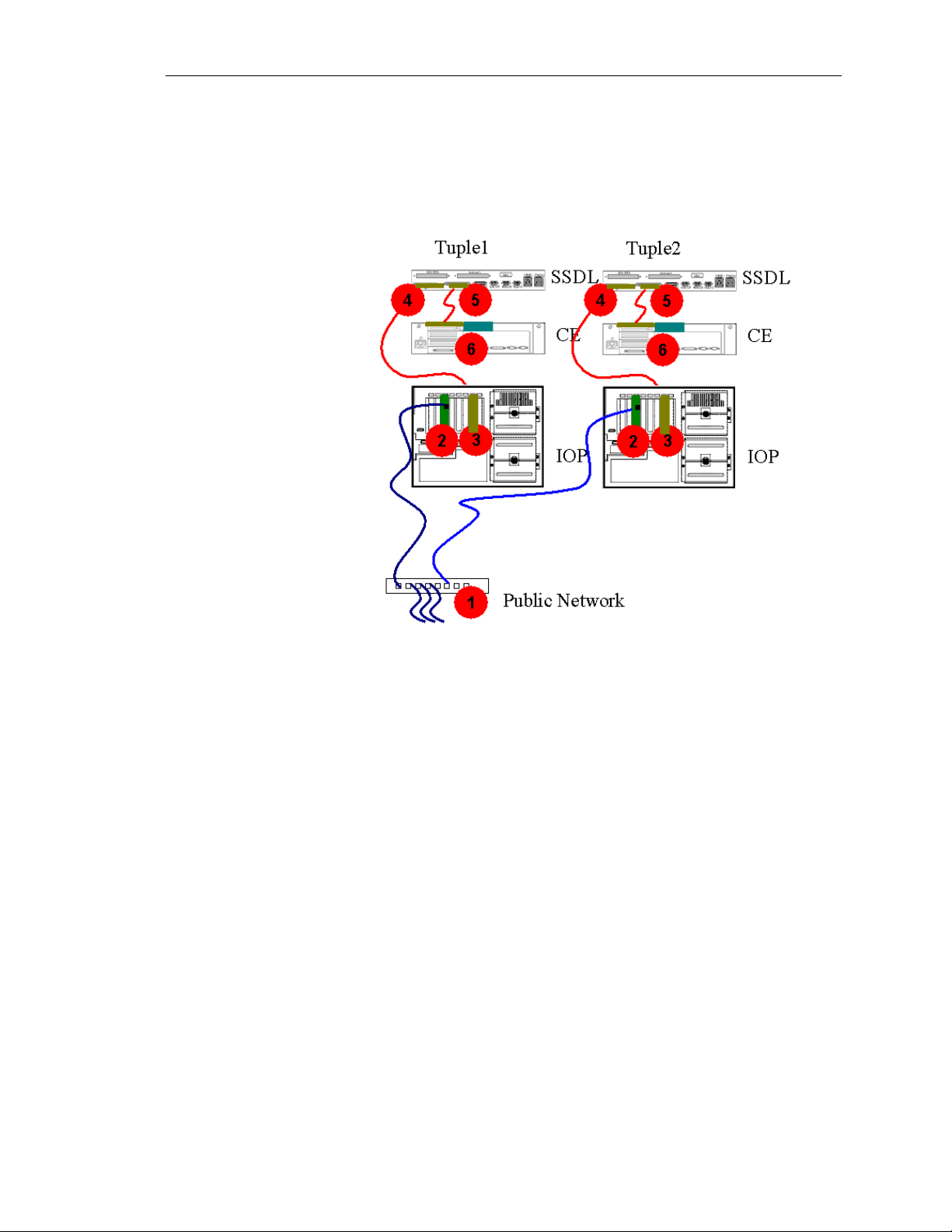
Putting it all together
Before the conclusion of the chapter, the following is a review of all
of the AA 4000 components and how they work together. Using the
diagram below, the best way to understand how the system works, is
to trace a typical client transaction with the HPAA system.
1. The client requests (for example) to perform a databse query.
2. The NIC on both IOPs has picked up the network traffic and will
immediately pass the packet to the MIC and later to the CE for
the parsing of the network packet. At this point the IOPs are not
looking at any information in the packet, it is simply acting as a
pass-through for all packets regardless of their intended
destinaiton.
3. The NIC passes the packet to the MIC.
4. The MIC on each IOP passes the packet to its own SSDL for its
tuple.
5. The SSDL passes the packet “as-is” to the MIC on the CE. At
this point the packet is going to both CEs from both SSDLs at
the same instance.
6. The CE looks at the packet and begins to do the parsing to
determine if the packet is to be “dropped” or passed on to the
rest of the OSI layers.
At this point the CE then performs the query to the database. It will
be accessing the disks on each IOP via the MICs. Each tuple will
perform this. At the CE level all I/O going in and out of the MICs in
1-16
Hewlett-Packard Company
Page 23

Ch 1: Architecture Overview and Terminology
synchronous. At the IOP level, due to the different spin rates of the
disk drives, the I/O is asynchronous.
The query results are eventually gathered by the CE (remember, the
CE is running the SQL server application, not the IOP) and passed
by both CEs to the SSDLs. The SSDLs both pass the network packet
to the IOPs for transmittal. And at the last instant, only one IOP
places the frame on the wire. The second IOP holds off so as to
avoid Ethernet collisions.
Network Server Division
1-17
Page 24
HP NetServer AA
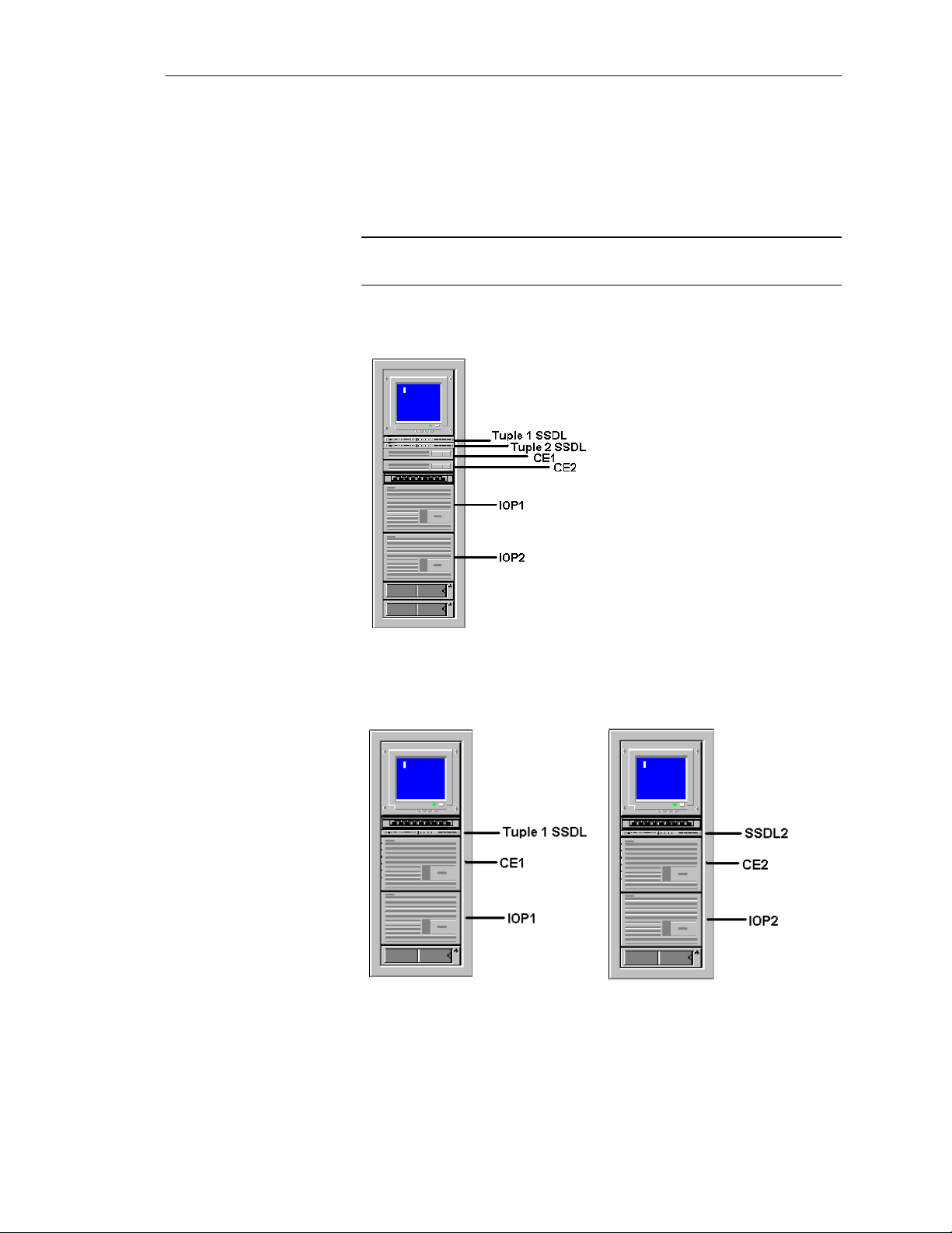
NetServer Rackmount Configurations
So far the diagrams used to describe the HPAA system have shown
the NetServers out of the rack to help illustrate the components and
their functions. The following is a look at the different
configurations available when ordering the HPAA system.
NOTE
These configurations are specifically for the AA 4000 and are as
of 3/2000.
NetServer LPr as the CE and LH 3r or LH 4r as the IOP
NetServer LH 4r as the CE and the IOP (two racks needed)
1-18
Hewlett-Packard Company
Page 25
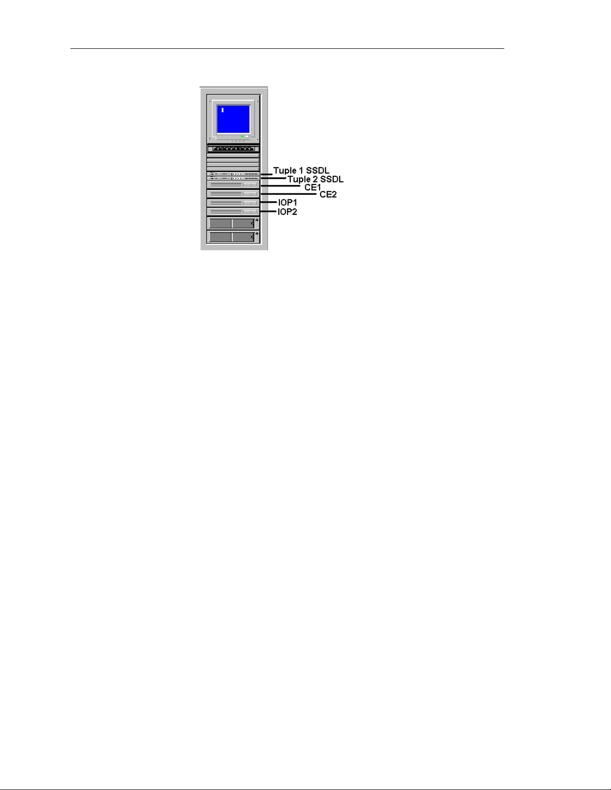
Ch 1: Architecture Overview and Terminology
NetServer LPr as the CE and the IOP
Network Server Division
1-19
Page 26

HP NetServer AA
Rules for maintaining availability
There really is only one rule when working with the HPAA system:
Always maintain the highest level of availability.
How is this done? Here are a few simple reminders to adhere to
when working with or adminstrating the HPAA system:
• Never shutdown the “server” with clients attached.
• Anytime one IOP goes offline for any reason while the CEs are
in operation, a disk re-mirror operation must take place after the
IOP is brought back online.
• To avoid unnecessary disk re-mirror operations, shutoff the CEs
during planned maintenance activities.
• One component can fail and the HPAA sytem still continues on
as if no failure took place. However, a second failure of the
same component generally means the HPAA system will be
unavailable.
• When changing, adding or deleting an IOPs AA 4000
configuration file, the same operation must be done on the other
IOP. The changes do not take affect until the next server reboot.
• The CEs are running the NT operating system that is used by the
applications and client network, all changes that need to be made
affecting these resources need tobe done on the CE, not the IOP.
• Changes to the NT operating system on the CE may not take
place until NT is rebooted (just like in a single server
environment). Take the appropriate precautions before rebooting
the CE’s NT operating system.
1-20
Hewlett-Packard Company
Page 27

Chapter Two ~ HPAA System Boot Up
This chapter covers the startup process for the HPAA system.
Before going through the details of powering on the system and
beginning to use it, the proper hardware connections should be
verified. In the event there is a problem with the basic connections,
how to use the MTCTEST utility ti troubleshoot will be covered
first. The remainder of the chapter will discuss the process from
power on to HPAA system online before the adminstrator can start
using the system. Topics to be covered include:
• Verifyng the MIC connections
• Powering up the system
• The different boot options
Ch 2: HPAA System Boot Up
• The HPAA boot process
• Proper shutdown of the system, and
• Using the correct keyboard and monitor view
Network Server Division
2-1
Page 28
HP NetServer AA
Verifying the MIC connections
Before booting the system, a quick visual verification of the
connections between the MICs and the SSDLs should be performed.
A more through verification can be performed using the MTCTEST
utility. It is important to make sure the MIC connections are good
before powering up the system and re-checking the connections
when a failure of any type occurs in the system. A quick visual
inspection can save hours of needless troubleshooting if in fact there
is a problem with a MIC cable or even the MIC itself.
Checking the SSDL LEDs
On the front of each SSDL are a series of LEDs that help verify that
the MIC cards are in good working order and the MIC cable
connections are correct. However, this is not the final verification
that all is in good working order. There are rare instances when all
LEDs indicate a working system, but there may still be a minor
problem with a MIC cable. The occurrence is rare enough that the
LEDs can be “trusted” and the cable connections can be ruled out as
the cause of a problem when troubleshooting. But in the rare
instance that all other troubleshooting is not pinpointing the problem,
the cable connections can be re-verified through the use of the
MTCTEST utility.
2-2
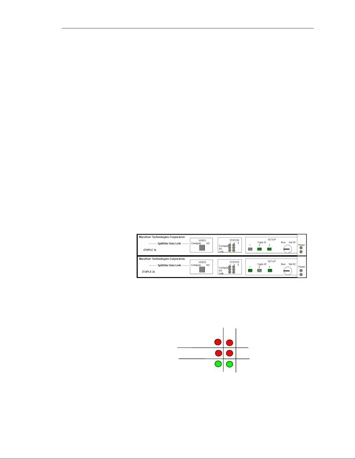
The above is a graphic of both SSDLs. In the middle of the SSDLs
are the LED indicators. Below is a close-up of how the LEDs are
organized.
2
1
3
Compute
I/O
Link
There are three columns for LEDs, the third column was for a
possible future development and is not used. Column 1 represents
tuple 1 and column 2 represents tuple 2. The Compute row shows
the status of the MIC connections from the CEs to the SSDLs (1 and
2). The I/O row indicates the status of the MIC connections from the
Hewlett-Packard Company
Page 29

Ch 2: HPAA System Boot Up
IOP to the SSDLs (1 and 2). The last row labeled “link” is for the
connection between the SSDLs.
When the SSDLs are not powered (not plugged in), the LEDs are
completely off. On the far right of the front of the SSDL are power
indicators; one for each power cord that can be used (the SSDL has
two power inlets for redundancy, only one is required). When the
SSDLs are powered, but the NetServers are powered down (standby
power), the LEDs will be red for the CE and IOP rows and green for
the “link” row. So a “red” LED is not necessarily an indication of a
failure, it could simply mean the server is not powered on. As each
NetServer is powered on, the MIC commnicates with the SSDL and
the LED representing the CE or IOP and the particular tuple changes
from “red” to “green.” At any time the HPAA system is fully
operational, all LEDs on the SSDL should be “green.”
If an LED is “red” check to see which connection it represents by
identifying the server role and in which tuple. Check to see if the
NetServer is powered up. If not, then a “red” LED is normal. If the
NetServer is powered up and the LED is still “red,” then there may
be a problem with the MIC cable connection for that node or a
problem with the MIC itself. In this case, a further inspection and/or
utility tests are needed to isolate the problem.
Tuple IDs
Also on the front of the SSDLs are tuple ID LEDs. And next to the
LED is a locking mechanism. The LEDs for the tuples are actually
buttons that can be pushed in implying that the tuple ID for the
SSDL can be changed. This is partially true.
WARNING
If a tuple ID button is pushed in that is not actually the
SSDL number it originally was configured at, not only the
ID will be changed, but also the SSDL will cease to
function.
The SSDLs are preset to belong to a particular tuple. Looking at the
back of the SSDL and seeing how it is labeled proves this. It is
recommended to verify the correct tuple ID LED is pressed and
remove the key and set aside somewhere safe and forget about using
it. Once the tuple ID is correctly set, the key is not ever needed.
Network Server Division
2-3
Page 30

HP NetServer AA
Troubleshooting a “RED” LED
When an LED is Red on the SSDL, the problem is the MIC cable,
the port it is plugged into, or the MIC itself. Troubleshoot this
situation as follows:
Disconnect the cable at the point where the LED indicates there is a
problem. For example, if the LED that interesects column 2 and the
“compute” row is red, then remove the cable from the MIC card on
CE2.
Check the pins on the cable and the port on the MIC. Re-insert the
cable by attaching the cable straight onto the MIC and turning both
screws by hand evenly until secure. Then use a Flathead screwdriver
to give the screws one more quarter turn to tighen. DO NOT overtighten. Check the LED again. If it still Red, move to the next step.
After the cable connection at the MIC has been eliminated as the
problem, the more difficult connection to access should be checked;
the connection at the SSDL. Using our same example, remove the
MIC cable on SSDL2 for the port labeled CE2.
The MTCTEST utility
Check the pins on the cable and the port on the SSDL. Re-insert the
cable by attaching the cable straight onto the SSDL and turning both
screws by hand evenly until secure. Then use a Flathead screwdriver
to give the screws one more quarter turn to tighen. DO NOT overtighten. Check the LED again. If it still Red, move to the next step.
Since both cable connections have been checked and eliminated as
the cause of the problem, attention is now focused on the MIC itself.
NOTE
It is possible that the SSDL has failed, but this is unlikely and not
checked unless there are multiple LED problems or other
symptoms.
To test the validity of the MIC and its ability to perform
communications, the MTCTEST utility should be used. However,
before performing the test, open the cover of the NetServer and
verify that the MIC has been properly seated into the PCI slot.
MTCTEST is a utility for testing MIC communications. The utility
can be found on the AA 4000 software CD under the /MTCUTILS
directory. The test cannot be used on a server that is booted into
Windows NT. MTCTEST is a DOS-based application that runs from
a bootable floppy. To use MTCTEST, copy the contents of the
/MTCUTILS directory to a DOS-bootable diskette and power up the
NetServer with the floppy. To fully test MIC communications, two
2-4
Hewlett-Packard Company
Page 31

Ch 2: HPAA System Boot Up
MICs must be used meaning the MTCTEST must be run on two
NetServers simultaneously.
NOTE
Create two utility diskettes for easier testing.
Before running the MTCTEST verify:
• All MIC cables and the tuple link cable are securely attached.
• The tuple ID LED buttons are correct on each SSDLl.
• The SSDL is powered on and all SSDL LEDs are green
MTCTEST confirms the following:
• The server can identify and access the local MIC registers and
RAM spaces over the PCI bus.
• DMA operations are working.
• A MIC can be located on the PCI bus and it responds to requests.
• A MIC can communicate with other MICs also running
MTCTEST.
• The communication paths (MIC cables and SSDLs) between
MIC adapters
Using MTCTEST
Boot two NetServers with a DOS-bootable floppy containing the
MTCTEST. To run the test simply type ‘MTCTEST’ at the DOS
prompt (make sure the DOS context is the correct directory). A
menu of different tests will be provided.
The tests available perform the following:
• Test 1: Reset MIC Adpater - Allows you to repeat the reset
sequence. This is usually not necessary because the MIC adapter
automatically resets when MTCTEST is started. This option may
momentarily cause other instances to fail if running option 4.
• Test 2: Verify Host < - > MIC RAM Access - Verifies host
access to the MICs memory-mapped RAM space. This
standalone test runs for approximately one minute. Use this test
if you suspect that the MIC/PCI interface is not operating
correctly.
Network Server Division
2-5
Page 32

HP NetServer AA
• Test 3: Verify Host < - > MIC DMA - Verifies the integrity of
the Host-to-MIC PCI interface by accessing DMA, RAM, and
runtime registers. Simulated MIC messages are transferred
through the MIC and looped back to the host where they are
verified for integrity. Failures in this test typically indicate a
problem with the DMA engine on the host or MIC adapters. The
DMA test completes after approximately one minute. When this
test is successful, the following information displays:
Starting Host<->MIC DMA test
456 MIC DMA operations successfully completed
833 MIC DMA operations successfully completed
1220 MIC DMA operations successfully completed
1663 MIC DMA operations successfully completed
2089 MIC DMA operations successfully completed
2390 MIC DMA operations successfully completed
MIC DMA test completed
If other information displays, a problem has occurred.
• Test 4: Verify MIC < - > MIC Commnication - Tests the
communication path between MICs and verifies the integrity of
all HP AA 4000 components associated with that path. For the
test to start, MTCTEST must be running at least one other MIC
(minimally, one CE and one IOP). This test runs until it is
stopped by manually pressing CTRL-C. Approximately one
minute of error-free runtime indicates a fully functional path.
The results of this test depend on the components participating in
the test. For example, the following is the result (reported on the
CE) while running this test between a CE and both IOPs.
2-6
Starting MIC<->MIC communication test - use
Ctrl-C terminate
Successful communication with IOP1 & IOP2 MIC
(120 messages)
Successful communication with IOP1 & IOP2 MIC
(231 messages)
Successful communication with IOP1 & iop2 MIC
(344 messages)
If the output does not indicate the communication was
successful, a problem occurred.
MIC Communication Test Paths
With four servers there are six different paths commnications
can occur between MICs. However, the MICs ability to function
needs to be only tested once per server. The most effective and
efficient way to test all MICs for functionality is to run
MTCTEST once on CE1 and IOP2 at the same time, stop the
test, then run it again on CE2 and IOP1 at the same time.
Hewlett-Packard Company
Page 33

Powering Up the HPAA System
There are up to eight components that need to be powered on in
order to use the HPAA system (not counting any UPS devices in the
rack):
• Four NetServers
• Two SSDLs
• Console Switch Box
• Monitor
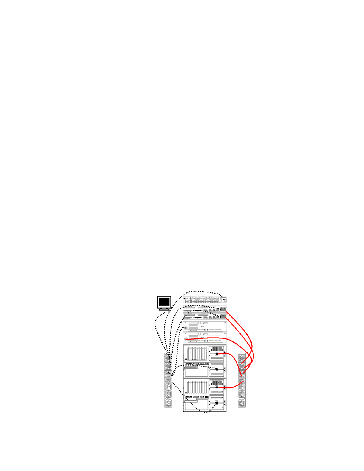
Before examining the power on sequence, first take a look at a
typical rack implementation and how it is cabled from the
perspectives of AA 4000 hardware, the console switch, and power.
Cabling the AA 4000 hardware
Ch 2: HPAA System Boot Up
Network Server Division
Once the peripherals have been added to the NetServers and all of
the components are rack mounted, including the SSDLs, then the
external cabling for the array can be completed.
The above diagram is an overall view of the cables directly related to
the array’s availability. One cable is used for the IOP Link; this is an
UTP CAT-5 patch cable. The rest of the cables are the 100-pin
ribbon cable that interconnects the tuples through the SSDLs.
CAUTION
Place the tuple cables in their respective connectors and
make a firm connection. Once the connection is made
correctly, then tighten the screw about half a turn. Do not
2-7
Page 34

HP NetServer AA
Recommended Cabling Order
When installing the ribbon cables, the following order is
recommended:
1. Connect the CEs to the SSDLs (5 feet cables)
2. Connect the IOPs to the SSDLs (5 feet cables)
3. Connect the SSDL Link (5 foot cable with ferrites)
4. Connect the IOP Link (Patch cable)
Do not force any cable connections or overtighten cable screws.
Cabling the Console Switch
overtighten, as this will potentially break the screw, or
cause the screw to be stuck and the cable cannot be easily
removed.
2-8
The SSDLs that are part of the HP AA 4000 Kit have video
connectors and the capability to switch video between the CE and the
IOP within one tuple only. A second SSDL allows for the same
capability for the other tuple, but this would require a second video
monitor. In this type of configuration, each tuple would not only
need its own monitor, but its own keyboard and mouse as well.
The HP Console switch eliminates the need for a second monitor,
keyboard and mouse. In conjunction with the SSDLs it allows for
Hewlett-Packard Company
Page 35
Ch 2: HPAA System Boot Up
the viewing of both CEs and IOPs. The HP Console switch has
specific cabling requirements.
To correctly cable the HP console switch within the array, use the
following steps.
1. Verify the Monitor, Console switch, and keyboard kit have been
rack-mounted
2. Gather the necessary peripheral cables
3. Connect the keyboard, mouse, and monitor to the Console
Switch
4. Connect Console Port 1 video to the SSDL for Tuple 1, the
keyboard to IOP1, and the mouse to IOP1
5. Connect Console Port 2 video to the SSDL for Tuple 2, the
keyboard to IOP2, and the mouse to IOP2
6. Connect Video extension cables from IOP1 to SSDL 1 and IOP2
to SSDL2.
Power Distribution
NOTE
The cables that are bundled with HP Console switches have the
monitor, keyboard, and mouse cables pre-tied and wrapped. To
be able to reach the SSDL for the video and the IOP for the
keyboard and mouse from the same wrap, the cable must be
carefully cut and the cables separated.
The HP AA Solution in a single rack should require no more than
two PDUs. The PDUs are not one per tuple, instead split the PDUs
Network Server Division
2-9
Page 36

HP NetServer AA
outlets to go to each tuple as pictured above. One of the PDUs will
have to be used for the video monitor.
Power On Sequence
NOTE
If four NetServer LH4s are rack-mounted in a single cabinet,
four PDUs are required.
UPS systems are highly recommended and should be used for each
PDU. For the optimum in power protection, AC sources should be
from different circuits, different phases, and different transformers to
two UPS systems and then to the rack to the extent possible.
Once the HPAA system has been racked, cabled, and the power
distribution setup, a few components are already powered on. The
SSDLs will be powered on and the NetServers are in standby power.
Before powering on the NetServers, first power on the console
switch and the monitor. The CEs cannot fully boot up until the IOPs
are booted, so the NetServer power on sequence is as follows:
1. Power on IOP 1 – Watch the POST and boot operation to make
sure the hardware is properly detected and working. When the
Windows NT menu comes on the screen, choose “Online
Marathon Mode” (the default) hit <Enter>. Move onto the next
system.
2. Power on IOP2 – Again, watch the boot operations, verify the
hardware and choose “Online Marathon Mode.” When the
second IOP has completely booted into Windows NT Server and
is on the logon screen, logon to one of the IOPs and launch the
Marathon Manager from “Start > Programs > Marathon >
Marathon Manager.” The console manager will display a status
of the array and the four servers.
The two bottom servers are the IOPs and they should be “green”
and in a ready state; the IOPs have “joined” each other. If not,
then launch the Marathon Manager on the other IOP, check error
2-10
Hewlett-Packard Company
Page 37

Ch 2: HPAA System Boot Up
logs, and start troubleshooting. Once the IOPs are joined then it
is time to power on the CEs.
3. Power on CE1 – Only power one CE at a time. As CE1 is
powered on, the POST and boot operations can be watched by
changing the console switch and SSDL. Shortly after the MIC is
detected in CE1, watch the Marathon Manager on one of the
IOPs to see the color changing sequence of CE1 while it is
booting into Windows NT. If CE1 goes to “green” and
Windows NT is running, then move on to CE2. If CE1 does not
boot, then check the NT error logs on the IOPs and start
troubleshooting.
4. Power on CE2 – Short after POST, it will not boot Windows NT
from the disks, but instead it will synchronize with CE1. It is
easy to see when the synchronization is taking place; the
synchronizing status is shown on the Marathon Manager on the
IOPs and CE1 is “frozen” while CE2 copies the contents of
Processor and System Memory. During synchronization the
source CE “freezes” for approximately 15 – 20 seconds per 256
MB of system memory; 1 GB of memory should be
synchronized in just over a minute.
Network Server Division
2-11
Page 38

HP NetServer AA
AA 4000 Boot Options
When powering on the IOPs and watching the boot process, the
Windows NT Boot Menu will appear. The boot menus may look
slightly different on each IOP because Windows NT was installed
twice on IOP1 and there are legacy Windows NT boot options. The
first three entries in the Windows NT boot menu are created during
the installation of the AA 4000 software. The boot options are:
• Online Marathon Mode - This option is the default and the
standard operating mode for the IOP. This option boots
Windows NT and activates the AA 4000 software. The IOP will
then attempt to join the other IOP and be prepared for a CE boot.
• Offline Marathon Mode - This is the best option for
maintenance. Selecting this menu option will boot Windows NT
and some of the AA 4000 software services. SCSI devices will
not be redirected and are available locally. The IOP is not active
in the AA 4000 configuration.
NOTE
Both IOPs must be active for the Endurance 4000 to be fully
fault tolerant.
• Marathon Maintenance Mode – Contrary to its name, this is
not the best choice for performing maintenance. This choice
should be reserved for emergency scenarios only. This option
boots a copy of the original Windows NT installed prior to any
AA 4000 software being installed. In other words, it is not the
same \WINNT directory and system files typically used during
normal boot.
The best use of this option is when there may be damage to the
regularly used NT system files. This option offers a “backdoor”
into accessing the \WINNT directory since while this copy of
Windows NT is active, it is using a different system directory.
Typically the system directory is called \MTCMAINT.
2-12
Hewlett-Packard Company
Page 39

AA 4000 Boot Process
IOP Boot
Ch 2: HPAA System Boot Up
The CE and IOP boot process are independent of each other with the
exception that the CE’s cannot start their boot sequence until at least
one IOP is available. If a CE is powered up before an IOP is
available, the screen of the CE(s) will display a text message that the
Marathon boot is in progress on a black screen. It will stay this way
until one IOP is in Marathon Operational Mode and the IOP has
checked up on the other IOP. Either IOP can initiate this process.
Once an IOP has started it will go into Online Mode as long as there
are no other configuration problems. When the second IOP comes
online it will contact the first IOP and check to see if a disk mirror
operation is necessary. The second IOP can be online while the disk
mirror takes place and provide redundancy for items other than the
disk. For example, IOP1 can provide a known good disk partition,
and while the mirror is taking place IOP2 can be providing the
network access.
The First CE Boot
The Second CE Boot
The first CE powered on will be looking to the IOP in its own Tuple
for an online state and use its boot disk within the Tuple. If its own
IOP is not online, it can use the boot disk from the other IOP
provided it is in a ready state. Once a boot disk is identified, the first
CE powered on will boot Windows NT. In the meantime, if the
second CE has been powered on, it must wait for the first CE to be
available for booting itself.
The second CE powered on is not booted from disk, but rather
performs synchronization with the first CE. This synchronization
consists of a memory dump from the first CE to the second CE.
While this memory transfer is taking place, the source CE is not
available. If viewing the display of the first CE powered on while
this synchronization takes place, the screen will appear to be
“frozen.” It takes approximately one minute per Gigabyte of
physical memory for the synchronization to take place. After the
synchronization is performed, both CEs are booted and in lock-step.
NOTE
The synchronization takes place after the repair or the re-booting
of the second CE. Some applications can be sensitive to the
synchronization “pause” which lasts up to two minutes. Most
applications can be configured to not restart after this period.
Network Server Division
2-13
Page 40

HP NetServer AA
Detailed Boot Steps - IOPs
When in doubt about what component is failing, watch the AA 4000
boot process from POST of the server to the POST of the system,
and at the same time, look at what the error logs are recording, and
watch the Marathon Manager console. Follow it along to make sure
each step is getting completed, and if not find the component
preventing any of the steps.
2-14
Detailed Boot Step – CEs
The boot process of the CEs is not only different than the IOPs; it
does not even start until the IOPs are prepared to accept the CEs into
the array. The graphic below shows what the CE must go through to
join the domain or an array.
Hewlett-Packard Company
Page 41

Using the Keyboard, Mouse, and Video
Once the HPAA system is powered up and all the NetServers are in
the array, it is important to always make sure when using the
keyboard and mouse that it is in the correct “context” of the
NetServer. And it is important to make sure the video displayed is
for the NetServer expected.
Video
This is the easiest to keep in correct context. By default when the AA
4000 software is installed, the backgrounds of the desktops on both
IOPs are changed. The background of IOP1 will have a tiled graphic
for Marathon with the word IOP1. The same is true for IOP2 except
obviously, it will have the work IOP2. The other video context is for
the CEs and though it is possible to be looking at a video of CE1
versus CE2, the two screens will always look the same since they are
in “lockstep.”
Using Two Monitors
Ch 2: HPAA System Boot Up
In the AA 4000 Users Guide and Installation Guide, an array is
typically cabled similar in logic to the diagram below:
If two video monitors are used, then to view a particular server in the
array, locate the monitor for the tuple you want to view, then use the
video switch on the SSDL to switch between CE and IOP video.
Network Server Division
2-15
Page 42

HP NetServer AA
Using One Monitor
Using two monitors is not practical, especially in a rack mount
environment. One monitor cabled to a console switch allows for the
viewing of any of the four servers. The SSDL video switch is still
used, so there are essentially two switches that have to be used in
conjunction with each other. To view any of the servers:
1. Use the HP console switch to choose one of the Tuples by hitting
the PrintScreen Button and selecting Port 1 for Tuple 1 and Port
2 for Tuple 2. (If the Ports are not labeled on the HP console
switch, take the time to label them using the F2 advanced menu
to avoid later confusion.)
2. Use the SSDL video switch for the chosen Tuple to switch from
CE and IOP.
Keyboard and Mouse Control
When the CE is booted, the AA 4000 software automatically moves
keyboard and mouse control away from the IOP to the CE. This is
another example of device redirection. Looking at the Marathon
Manager Utility will show the status of the redirection of the
keyboard and mouse. When the keyboard is green it is under control
of the CE, when it is white it is under the control of the IOP. To
change control between the CE and IOP, press <CTRL> <SHIFT>
<F12>; the key sequence will allow the user to regain control of the
keyboard and mouse.
Just like the choice to use one monitor or two, there is also a choice
of using one set of a keyboard and mouse or two depending on if the
HP Console Switch is used.
No HP Console Switch
In the diagram that shows the array using two monitors, notice there
is also two keyboard and two mice. When the array is booted
keyboard and mouse control are automatically passed to the CEs. To
perform an operation on the CE, simply choose one of the keyboards.
It makes no difference which one since both of them control the CEs
and any keyboard or mouse movement on one CE will instantly
appear on the other CE due to being in lockstep.
Using the HP Console Switch
To use the keyboard and mouse on a specific NetServer, press the
PrintScreen key to bring up the Console Switch menu, choose Port 1
for Tuple 1 or Port 2 for Tuple 2. Most of the time the screen that
will appear will be the CE and it will have keyboard control. If it is
the IOP that needs to be accessed, press the video switch on the
2-16
Hewlett-Packard Company
Page 43

Ch 2: HPAA System Boot Up
SSDL for the tuple being accessed and then press <CTRL>
<SHIFT> <F12> to gain control of the keyboard and mouse.
Network Server Division
2-17
Page 44

HP NetServer AA
Shutting Down the System
There are various methods to shut down the system, power down the
system, or remove a component from the array. It is imperative that
the administrator understands what the goal is before issuing a
command to the system that removes the component or shuts down
the system. Keeping in mind that the HPAA system is a high
availability solution capable of running for a year with virtually no
downtime, the administrator can take action that diminishes the
systems fault-tolerant status, so the utmost caution should be taken.
There are generally two methods to change the status of a
component: (1) issue a command at the command prompt using the
MTCCONS.exe comand, or (2) use the “Display and Control”
window in the Marathon Manager Utility.
The following actions will degrade the redundancy of the array or
make the array unavailable to client network access:
• Removing or Disabling a CE
• Removing or Disabling an IOP
MTCCONS.exe
• Issuing a CE Operating System Shutdown Command
• Issuing an IOP Shutdown Command
• Issuing a “server” Shutdown Command
• Issuing a “server” Reboot Command
NOTE
There is a major difference between a shutdown and a disable
command. This will be explained throughout the remainder of
this chapter.
Upon installing the AA 4000 software, the MTCCONS.exe utility is
made available at the Windows NT command prompt. The utility
allows for AA 4000 commands to be executed from an MS-DOS
window or a Windows NT command prompt window. The primary
reason for using MTCCONS (Marathon Manager console
commands) is to execute scripts for system validation (test) or
system management. When using MTCCONS, you must enter the
exact command syntax and any required parameters. Each command
has the following components: ‘Prefix’, ‘Target’, ‘Verb’, ‘Operation
type’, ‘Executed from’ and any associated ‘Parameters’.
2-18
Hewlett-Packard Company
Page 45

Removing Components
Ch 2: HPAA System Boot Up
For more information on using MTCCONS, see the AA 4000 Users
Guide.
Most components of the HPAA system can be removed from
participating in the array. The advantage of being able to take this
step is to proactively remove a component for maintenance that will
prevent the AA 4000 software from reporting the same errors again
and again, or worse, “failing” the component out of the system. A
component that has been “failed out” must be manually enabled
upon repair. For the purposes of administering the HPAA system,
the terms “remove” and “disable” are synonomous.
Disabling (Removing) a CE
This command disables (removes) the specified CE from the active
AA 4000 configuration. For the CE to rejoin the array use the CE
Enable Operation command.
WARNING
If only one CE is in operation, use a Windows NT
Shutdown whenever possible. This command does not
perform a normal Windows NT shutdown. As a result, any
data in the NT disk cache that has not been written to disk
can be lost.
Using MTCCONS
MTCCONS CEn Disable Operation From IOPx disable_safeguard
Using Display and Control
Double-click on the picture of the CE to be disabled and from the
Control and Display window choose the disable command.
Once the operation is performed, the CE resets, goes through POST,
and reboots. The CE reinitializes, but cannot boot or synchronize
with the AA 4000 array until a CE Enable Operation command is
issued. To verify that the CE is disabled, on either IOP or the
remaining CE check the status in the Marathon Manager Main or
issue an IOPn Show Configuration command.
Network Server Division
Disabling (Removing) an IOP
This command disables (removes) the specified IOP from the active
AA 4000 array. Use this command to start a maintenance procedure
or to remove an IOP that is not operating properly (this will allow a
verification to take place to see if the system operates correctly
2-19
Page 46

HP NetServer AA
without it). For a disabled IOP to rejoin the array issue an IOP
Enable Operation command. Before disabling an IOP, verify that:
• The IOP to be shut down is not marked as the source of a mirror
copy.
• Make sure that the other IOP is active.
• If possible, perform any necessary backups for non-mirrored
devices on the IOP to be shut down.
• Make sure that the other IOP has public network connectivity
(IOPx.Ethernet cable is online).
WARNING
When this command is issued, all I/O devices on the
specified IOP are unavailable to the CEs.
Using MTCCONS
MTCCONS IOPn Disable Operation From IOPx
Using Display and Control
Double-click on the picture of the IOP to be disabled and from the
Control and Display window choose the disable command.
Shutting Down the IOP
When (disabling) removing the IOP, it will attempt to reboot and
then it will simply not participate in the array. To completely
shutdown the IOP, after issuing the shutdown command, issue a
Windows NT Shutdown without Restart then power off the system
when prompted.
Issuing a CE Operating System Shutdown
2-20
This command allows for an Operating System restart that may be
necessary when changing the configuration for Windows NT or
installing an application. The command is seldom used, but could be
a shortcut to restarting the OS without completely shutting down the
servers or the HPAA system.
Using MTCCONS
MTCCONS CE_O/S Shutdown Operation From IOPx
Using Display and Control
Double-click on the picture of the CE and from the Control and
Display window and choose the CE-O/S shutdown command.
Hewlett-Packard Company
Page 47

Server Shutdowns and Reboots
By now, it is apparent that MTCCONS or the Marathon Manager can
be used to change the status of a component or the entire system.
Server shutdown commands are no different. The most important
aspect of a server shutdown to note is not the command to execute a
shutdown, but instead knowing how to perform an actual shutdown
and not just a reboot.
Whenever a ‘shutdown’ command is issued, the array will attempt to
reboot. If an actual shutdown is desired, then power off the servers
before they can reboot. One other way to prevent the servers from
trying to be a part of the array after a shutdown is not to issue a
shutdown command, but rather, issue a disable command. Just
remember, any component that has been disabled must be manually
re-enabled; the AA 4000 software does not automatically enable
components.
Avoiding Unnecessary Re-Mirror Operations
When performing shutdown commands, it is imperative to
understand that any shutdown of an IOP while a CE is still active
will result in a full disk re-mirror when the IOP is brought back
online. If the intent is to perform maintenance on the system as a
routine and steps have been taken to not require system availability,
make sure to shutdown CEs before IOPs.
Ch 2: HPAA System Boot Up
CAUTION
A disk re-mirror takes approximately 4 – 5 minutes per
Gigabyte of disk space. Re-mirrors are not just the data, it
is a block-by-block operation.
Network Server Division
2-21
Page 48

HP NetServer AA
Using the “Right” Copy of Windows NT
The HPAA system features three distinct installations of Windows
NT in operation; one each for the IOPs and one for both of the CEs.
Remember, the CEs operate in lockstep and use the same copy of
Windows NT. Regardless of which CE is being viewed based on the
tuple choice, any modifications made to Windows NT on the CE
occurs once, but it written to two different disks on each IOP for
redundancy.
When to use Windows NT on the IOPs
When working with the Windows NT operating system on the IOP,
it has no bearing on the other IOP. All administrative tasks
performed on one IOP for the purposes of the HPAA system most
likely have to be performed again on the other IOP.
When the HPAA system is first delivered, there are only the default
user accounts and groups on the Windows NT operating system on
each IOP. The first administrative task would be to change the
administrator password as a security precaution on each IOP.
During normal operation of the HPAA system, the IOPs do not
require any access or adminsitrative use other than to use the
Marathon Manager. The Marathon Management Tool is installed on
each of the IOPs and it useful for:
• Getting a status update on the array from the IOPs perspective
• Checking the status of the array in the absence of a working CE
• Performing / Issuing Marathon-based administrative commands
when the CE is not available
The IOPs do support the installation of additional applications, but
other than management tools this is not recommended as other
applications may impact the availability of the IOP and impact the
performance of the overall array.
When to use Windows NT on the CEs
The short answer is almost always. The copy of Windows NT is the
copy that supplies the resources for the client network. It is where
all applications are installed. When installing applications and
configuring the server to have the tools and accessories needed to
optimize performance conditions and services for the network,
always think in terms of the CE. Some of the typical administrative
tasks in a Windows NT environment to be done on the CE include:
2-22
• Joining a Domain – The CE copy of Windows NT is typically a
stand-alone installation of Windows NT Server. In the network
Hewlett-Packard Company
Page 49

Ch 2: HPAA System Boot Up
properties of NT, the administrator can join the NT domain as
normal.
• Setting up security – Whether the CE remains as stand-alone
server or joins an NT domain structure, security precautions
must be taken. This includes tasks like changing the
Administrator password, bringing domain users into local groups
on the server, applyng permissions to users, etc…
• Installing Applications – The first thing to consider is are there
enough resources to run the application? Be sure to install the
amount of system memory needed to run the aplication. Both
CEs mus have matching amounts of system memory. The CEs
support 1 CPU currently up to 600 MHz and up to 1 GB of
system memory; this is enough to support most mid-range and
up application environments.
• Setting up file shares – By right clicking on the “Network
Neighborhood” icon on the desktop and choosing “Properties”
the server will name will be shown. This is how the clients will
access the server (the array). Set up file shares and set up the
clients to point to the right server name for the array. The IOP
server names are only useful for administrating the IOPsand
have little to do with the client network.
Network Server Division
2-23
Page 50

Page 51

Ch 3: AA 4000 and HP management Tools
Chapter Three ~ AA 4000 and HP Management Tools
Mangement of the HPAA system is made easy by the use of the
Marathon System Management Utility (MSM) or “Marathon
Manager” for short. This tool can be run on any of the systems in
the array or on a client. Other management tools available are from
theHP suite of management tools. However, there are some
limitations. In this chapter the topics covered include:
• A brief look at the software architecture of the AA 4000
• Installing the Marathon System Manager (MSM)
• Using the various tools within the MSM
• Installing and using the HP TopTools family and ManageX
Network Server Division
3-1
Page 52

HP NetServer AA
AA 4000 Software Architecture
The main value of the HP AA 4000 software is its ability to “split”
the Windows NT architecture and allow the IOPs to function as the
I/O agents of the CEs. Looking at the array as a whole and the
Windows NT architecture, what is in effect happening is the CEs are
operating in User mode and the IOPs are operating in Kernel mode.
However, the reality is the CEs are running one synchronized copy
of Windows NT and its I/O traffic is that of the Marathon Interface
Card. The IOPs are each running their own copy of Windows NT
and spending most of the time servicing the I/O requests that come
through the MIC. For disks, this is divided up between disk.sys
running on the CEs and scsiport.sys along with the device drivers are
running on the IOPs. For the network, the NDIS on the CEs ends up
with its I/O on the NDIS of the IOPs. All device drivers operate on
the IOPs.
3-2
There are five key areas in the software architecture:
• I/O Redirector – In the CE’s, for each supported device, the
redirector intercepts I/O requests in the CE and moves them to
the IOPs through the Marathon Transport.
• I/O Provider – On the IOPs, this counterpart to the CE’s
redirector receives requests from the CEs through the Marathon
Transport and sends them to the Windows NT device drivers
local to the IOP. The providers also handle incoming I/O
(networking) and pass it to the CE redirectors through the same
Marathon Transport.
Hewlett-Packard Company
Page 53

Ch 3: AA 4000 and HP management Tools
• Marathon Transport – This handles all data movement within
the array where the redirectors and providers are concerned. It
works in conjunction with a Device Synchronization Layer to
make devices appear as one to the CEs and move the data using
Marathon Interface Cards (MICs).
• Monitor – This is in charge of all state transitions, reports status
to the Marathon Manager, and executes various Marathon
manager commands. Within this component is a discrete
component known as the fault manager. The IL and other
subsystems depend on the monitor to go online.
• Device Synchronization Layer – Synchronizes all redirected
I/O requests from the CE to the IOPs and all responses from the
IOPs to the CE. This is necessary to account for the difference
in hard drive spin rates and caching among other latency
potentials, by the IOPs. It also ensures that common resources
and requirements are provided.
Network Server Division
3-3
Page 54

HP NetServer AA
Marathon System Manager (MSM)
The Marathon System Manager (MSM) is a GUI-based tool which
runs on the local copies of NT Server within the array or on a NT
Workstation client. In either case, Administrative equivalent access
to the NT Servers is necessary to manage the array. This permission
would be set in the User Administration Tool of the CE.
The MSM is the primary tool for array management and status
monitoring. All activity in managing the array starts with this tool.
All troubleshooting scenarios should also start with this tool
whenever possible to get a quick status check of the health of the
entire array.
3-4
The MSM is installed on the IOPs, CEs, or clients as part of the
Marathon software installation or separately. Along with the
installation of the management software is the installation of its
associated command tool: MTCCONS.exe. This tool can be used at
the NT command line for carrying out commands on the array. As a
command line tool it can also be used for scripting commands or
maintenance activities.
Hewlett-Packard Company
Page 55

Remote Management
Ch 3: AA 4000 and HP management Tools
The Marathon Manager can be installed on a remote workstation to
administer the AA 4000 array. Connection can be done using either
a local area network or a modem. After installing the Marathon
Manager and establishing the remote connection, the administrator
can use Marathon Manager features and options to administer an AA
4000 array.
When using Marathon Manager on a remote workstation:
• For security purposes, each Remote Marathon Manager user
must have an account on the local and remote systems. These
accounts must have the same username and password. In
addition, the user must be a member of the Windows NT
Administrators group on the remote system.
• Enter the CE computer name for the Endurance 4000 that you
want to monitor in the Server name field.
• When Marathon Manager is connected to a remote Endurance
4000, the computer name of that Endurance 4000 is displayed in
the title bar of the window.
• Marathon Configuration Utility only operates on an IOP.
Because of this, the Marathon Configuration Utility (the
Marathon Manager, Tools Marathon Configuration Utility
option) is not available on any remote workstation or the CE.
• The Tools Marathon Events Utility option (MTCLOG) is not
available using Remote Marathon Manager.
• On the Tools Windows NT Utilities menu, only the following
options are available:
• Event Viewer
• Explorer
• Performance Monitor
• Registry Editor
• On the Tools Windows NT Utilities menu, when you select
Event Viewer or Registry Editor, you must use the application’s
Select Computer option to access the remote AA 4000’s Event
Viewer or Registry Editor.
• Using Microsoft’s Remote Access Server and Marathon
Manager, you can use a remote workstation to administer your
Endurance 4000. Depending on your remote Marathon Manager
configuration, this combination provides access to either or both
IOPs.
Network Server Division
3-5
Page 56

HP NetServer AA
MSM – Main Screen
Upon installation, the Marathon Manager is available through the
Windows NT Start button > Programs > Marathon > Marathon
Manager, or, Start > Run and type mtcmgr. When launching at
the CE or the IOP, the MSM will automatically connect to the local
array. The MSM has the ability to manage remote arrays by typing
in the server name in the lower right-hand corner and clicking on the
update button.
Upon the launching of the MSM, a typical view will consist of:
• Administration Window – A graphical representation of the
array
• Device Status Window – A list of all the components and their
status
• Last Mirror Copy Status Window – Detailed information on
the progress or completion of disk mirroring activities
3-6
Hewlett-Packard Company
Page 57

Control and Display
Ch 3: AA 4000 and HP management Tools
From the tools menu is the Control and Display window that acts as
a command initiator window. This screen is also available by double
clicking on a component in the Administration menu. The window
displays the commands, options, and parameters that allow for array
management and the displaying of detailed component status and
configuration information.
Network Server Division
3-7
Page 58

HP NetServer AA
Control and Display Options
OPTION DESCRIPTION
Command Description When a command is selected, this area displays a brief
Filters Applies a filter to the target field to display subsets of the
Target List the available components on which commands can be
Operation Displays the components available for the selected action to
Executed Specifies the IOP from which the action and operation should
description of the command.
various components.
performed. For each command selected, a target must be
selected.
be performed.
be performed only on some commands.
Parameter Enter parameters such as intergers or true/false flags of a
command that supports it.
Verbose Output When checked, the executing of some commands will result
in a more verbose display of the result.
Confirm Command By default on some commands, the Marathon manager will
prompt for a "verify" or cancel.
Operator override Allows for the disabling of an active component that does not
have an active redundant counterpart. This extra step helps
prevent accidental disabling of components.
Apply Executes the selected command
Close Closes the window and returns to the Administration window
Help Opens Marathon Manager online help
3-8
Hewlett-Packard Company
Page 59

MSM Preferences
Ch 3: AA 4000 and HP management Tools
From the tools menu, select options to get to the preferences screen.
This screen configures the monitoring parameters. The time in
seconds between updates can be set for the Administration window
through polling and the time can be set for refreshes of any windows
displayed as a result of the show command. The setting of 0 seconds
will disable any automatic updating.
The parameters are set for each perspective, meaning, whatever
polling options are set when using the manager on a CE, is
independent from polling parameters set when viewing from the
perspective of the IOP.
Network Server Division
3-9
Page 60
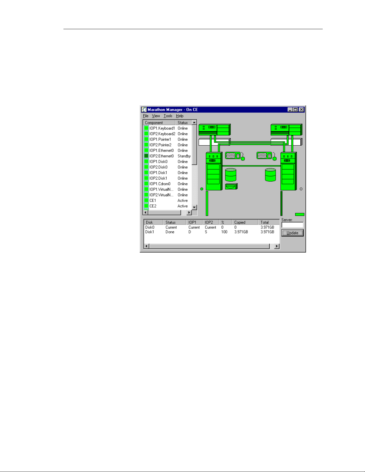
HP NetServer AA
Device Status
The device status screen can be seen as part of the main
administration view. It will not be seen as the default when
launching the MSM. To view the status screen as a separate
window, check the appropriate box in the preferences (options)
screen.
3-10
Hewlett-Packard Company
Page 61

Ch 3: AA 4000 and HP management Tools
The following is a color legend to help interpret the status of each
component:
Color Component Indicates
Blue All Booting* or Joining*
Blue-Green All Ready
Dark Green Ethernet Adapters
Interconnects
SCSI Disks
Keyboard / mouse
All others
Standby
Online
Destination disk of a mirror
Online, but in arbitration
Initialized*
Dark Grey All Disabled
Light
CE’s, IOP’s. MIC’s
Active
Green
Keyboard / mouse
All others
Available to CE’s
Online
Light Grey All Unknown
Red Keyboard / mouse
Not available to the CE
Yellow SCSI Disks
White Keyboard / mouse
*Indicates a state that only occurs during system transition
Network Server Division
All others
Ethernet
All others
All others
Offline
Mirror Copy is pending
Disconnected
Offline or Shutdown*
Available to the IOP
Initializing
3-11
Page 62

HP NetServer AA
Last Mirror Copy Status
Just like the Device Status window, the mirror copy status window
appears on the main administration view by changing the preferences
(options).
Because this window displays the last mirror copy status from a
particular IOP, it is possible for the IOPs to return last mirror copy
status reports that appear slightly different. Any IOP that is actively
serving the CEs (it is online) will provide complete and current
mirror copy status reports.
3-12
Hewlett-Packard Company
Page 63

Utilities
Ch 3: AA 4000 and HP management Tools
From the Tools menu, the administrator can access commonly used
Windows NT utilities. The NT utilities available are:
• Control Panel
• Disk Administrator
• Event Viewer
• Explorer
• File Manager
• Notepad
• Performance Monitor
• Registry Editor
Network Server Division
The Tools menu also provides access to the Marathon Configuration
utility and a Marathon Event viewer / utility.
NOTE
These utilities are invoked on the local system where the
manager is operating, even if monitoring a remote server. The
default context of the local machine will be shown for each
utility.
3-13
Page 64

HP NetServer AA
Display Software Revisions
From the View Menu, the Revision Levels of the various software
components can be seen in one central location. The software
revisions displayed are from the perspective of the IOP of run on the
IOP or of the CE if run on the CE or from a client workstation.
The screen is useful when collecting data about software updates /
patches, firmware revisions, and the Marathon Kit number.
The Revision Levels header shows the version number and a twoletter identifier for the type of revision. The abbreviations are as
follows:
• RL: Release
• HF: Hot Fix
• SP: Service Pack
3-14
Hewlett-Packard Company
Page 65

HP TopTools Remote Control Card
HP NetServer AA Solutions have powerful and intelligent
management tools. HP TopTools Remote Control Card, which
comes standard in enterprise-class HP NetServers and as an option
for most other HP NetServers, conducts efficient remote
management and transmits basic device information to HP TopTools,
through Microsoft Internet Explorer. Currently, this tool is
supported on the CEs and IOPs in the array. However, functionality
is very limited for the CE’s. The Remote Control Card operating in
the compute element will be helpful in collecting data on the system
environmentals (fan speed and temperatures), but little else. For the
IOP, the Remote Control Card should have full functionality.
HP TopTools and Agents
HP TopTools and TopTools agents are not currently supported in the
Compute Elements. The CE’s are running in lockstep and the two
systems could report information such as temperature back to
Marathon software that would not be the same for the two systems.
This may cause one of the systems to fail out.
Ch 3: AA 4000 and HP management Tools
ManageX
NOTE
TopTools agents should not be loaded on the Compute Element,
as it will cause failures.
For the IOPs, the full version of HP TopTools and the agents are
supported. However, an additional network card is needed to access
the HP TopTools information on the IOP considering that the
remaining network cards are “redirected” and owned by the CEs.
The NIC used for accessing TopTools Management information
would not be redirected and need to have a separate IP address
accessible by a client running a Internet browser and the TopTools
client software. This network card dedicated for TopTools
management on the IOP can also be used as the path for a netowkr
backup (this is covered in more detail in Chapter Seven).
HP OpenView ManageX provides the complementary capability,
orchestrating advanced NT system administration and application
management. With ManageX administrators create policies which
set thresholds to take action on specified events. For the HPAA
System, ManageX can capture the events reported to the NT Event
log of the CE’s or IOP’s and forward those events as defined in the
ManageX notification pages.
Network Server Division
3-15
Page 66

Page 67

Chapter Four ~ Networking Explained
Given the fact that the HPAA system provides application services to
the network, it is very important to install and configure the network
components correctly. There are three different network types at
work when using the HPAA system. Though all three networks use
standard networking properties in Windows NT, their configurations
differ slightly. Careful attention to detail must be made in the
network configurations in order to ensure initial and continuous
operation of the HPAA system. In this chapter the topics covered
include:
• The three different network types in the HPAA system
• Using the Marathon Configuration Utility to make networking
available to the CEs
Ch 4: Networking Explaineds
• How to configure each of the network properties in Windows NT
• How to add or replace a network card(s)
Network Server Division
4-1
Page 68

HP NetServer AA
Network Planning
PCI Slot locations
Before installing and configuring network adapters it is important to
plan the networking environment in order to determine the number
of network cards needed, the PCI slots they are installed in, which
subnet they will be connected to and the necessary networking
protocols.
Most of the network planning and configurations of the network
cards may have been done as part of the initial order of the system.
At a minimum, the HPAA system will arrive with one public rail
configured and ready to start networking (the TCP/IP settings may
need to be changed).
The AA 4000 based HPAA system supports the HP NetServer LH 3
or LH 4 as the IOP. All of the network cards are installed in the
IOPs. The LH 3 and LH 4 have the same I/O structure, so slot
recommendations are the same for both NetServers. The easy
recommendation to remember is the Marathon Interface Card (MIC),
it should be in PCI slot 7 or 8.
The network cards should be placed in different PCI slots depending
on their roles. The optimum PCI slots for performance in order are
PCI slots 2, 3, 4, 5, and 6. PCI slot can be used, however it is a
shared ISA slot and they may impact the NetServer configuration in
other areas. PCI slots 4, 5, and 6 are behind the i960 processor used
for the NetRAID operations as well as providing a PCI bridge. For
that reason, PCI slots 2 and 3 perform slightly better than slots 4 – 6.
Keep in mind for the ease of upgrading in the future; the network
cards are supported in any PCI slot.
Given the choice of PCI slots based on performance, the following
are some general recommendations for using the PCI slots for
networking:
PCI Slot 1
PCI Slot 2
PCI Slot 3
PCI Slot 4
Backup/Management LAN for IOP
Public Rail #1
Public Rail #2
Public Rail #3
4-2
PCI Slot 5
PCI Slot 6
Public Rail #4
IOP “Private”Link
Hewlett-Packard Company
Page 69

Windows NT Bus Numbering
Network services, protocols, and bindings will have to be configured
as part of the software installation. Working with multiple network
cards and configuring software parameters can sometimes be
confusing when mapping the physical slots to what the operating
system displays. It is imperative that the relationship between
physical slots and Windows NT slot numbering is known. Incorrect
bindings and protocols on the network cards can cause problems for
disk mirroring and client/server access.
One strategy of making sure the correct bindings go with the right
card in a particular physical slot is to only install and configure one
network card at a time. This may work with a simple cluster
configuration, but it is not practical in this environment.
Understanding the relationship of physical cards to software settings
is preferred to maintain availability of the system when performing
configurations, upgrades, or maintenance.
How Windows NT sees it…
Ch 4: Networking Explaineds
In general, Windows NT will number the PCI slots in the order they
are detected. NT will detect PCI slots in the order of the PCI bus
detection and also assign slot numbers to detected PCI bridge chips.
As noted in the slide above, the NT detection of the PCI slots in the
NetServer LH 3 and 4 starts with Bus 0 Slot 8 (physical) and assigns
it Bus 0 slot 1 (software). As it makes its way to a new bus, the first
slot goes to the bridge chip and then the PCI slots. For example, Slot
5 (physical) in the LH 3 and 4 is assigned Bus 1 slot 3 in Windows
NT.
NOTE
When in doubt of which slot a card is located in, refer to the
information printed directly on the I/O board instead of the
external case numbering.
Network Server Division
4-3
Page 70

HP NetServer AA
Gathering Networking Information
In order to successfully configure the network cards, gather the
following information:
• MAC addresses
• PCI Slot location
• Subnet attached to / planned TCP/IP address
This information will be used to configure the network cards in the
Marathon Configuration Utility and the Windwos NT Network
Propeties.
Three Independent Networks
There are three distinct network types in operation for any
implementation of the HPAA Solution.
The first network setup is the IOP Link or private network. Similar to
a “heartbeat” network link in a clustering environment, this network
is responsible for internal IOP-to-IOP communications and it also
carries disk-mirroring traffic.
The next network type is commonly referred to as a public rail or the
redirected network. Using specific Marathon protocols this network
comes in two parts, the software on the CEs and the
software/hardware implementation on the IOPs. This network is used
for client access.
The last network type is the virtual network. To simplify
maintenance and access to resources, an internal system network is
created for the CEs and IOPs. This provides a mechanism for CEs to
see resources exclusively provided by the IOPs and vice-versa. The
network is “virtual” because it does not consist of network interface
cards. The traffic is carried out by the MICs.
4-4
Hewlett-Packard Company
Page 71

The Private Network (IOP link)
As mentioned earlier, the IOP Link is a private network for the IOPs
to monitor each other and transport data for mirror copies. The
network is essentially a two-node Ethernet network directly
connected by a CAT5 UTP crossover cable, or connected via a hub
or switch in SplitSite configuration. Gigabit Ethernet is also
supported as a network medium for the IOP link.
Ch 4: Networking Explaineds
IOP Link Configuration
The most important aspect of the IOP link is the network parameters.
These must be set in a way to maximize throughput. In a standard
implementation or Central configuration, two 10/100 HP TX cards
are used and must be set at 100 Mbps and Full Duplex mode. Do not
rely upon the “Auto” setting, which is the default property of the
network card, to be sufficient in guaranteeing the correct bandwidth
settings. As the provider of the mirror copy data path, an incorrect
network setting can have a significant affect on performance. If the
network card is set in half-duplex mode, the problems experienced
by the HPAA System when performing a mirror copy operation is at
best slow throughput (about 3 MB/sec) and usually will result in a
failed mirror copy as well as a failed IOP that must be manually
enabled.
NOTE
The IOP Link can be a 100FX configuration using fibre
connections.
Other than making sure the HP 10/100 TX cards are set to a fullduplex mode, the other areas of configuration that are critical are the
proper settings of the network properties concerning services,
protocols, and bindings.
Network Server Division
4-5
Page 72

HP NetServer AA
Before any Marathon software implementation is performed, two
pieces of data need to be collected: (1) the MAC addresses of the
network cards to be used, and (2) the verification of the PCI slot use.
4-6
Armed with the above information, the protocols and services can be
set up on known, good equipment. The bindings to be deployed as
part of the Network card configuration are a traditional networking
protocol of choice (NetBEUI, TCP/IP), the MtcEtx Driver, and the
Marathon Datagram Service. These bindings go on the card chosen
as the private IOP link as represented by the correct bus and slot
number according to Windows NT.
There is only one network card in each IOP with these bindings, the
cards do not support Adapter Fault Tolerance, and they are NOT
“redirected” devices to be configured in the Marathon Configuration
Utility.
Hewlett-Packard Company
Page 73
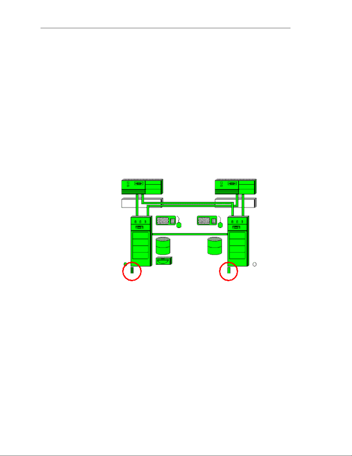
The Public Network (Ethernet Rails)
A pair of network cards, one in each IOP, in the same PCI slot
numbers constitutes a “public rail.” There are several different
terminologies used for essentially the same network type. For the
network cards that the IOPs use to intercept client traffic on the
network, these cards may be referred to as the public network, a
public rail, or an Ethernet rail.
As far as the requirements for the AA 4000 software go in regards to
the network cards to be used as the public network, any NDIS 4
compliant network card with Windows NT 4.0 drivers will work.
These cards also must support the capability of having their MAC
addresses “soft-set” by the Marathon software into the NT registry.
This is part of NDIS 4 standards, so any of these network cards
should comply. For the purposes of the HPAA system, the public
network cards will also be HP 10/100 TX cards.
Ch 4: Networking Explaineds
Network Server Division
Additional public rails can be added to the array. Up to four public
rails, or four pairs of NICs, can be added to the IOPs in addition to
the IOP link. For a NetServer LH 3, the five network cards would be
inserted into PCI slots 2 – 6 with slot 6 functioning as the private
link.
Each public rail as represented by the pair of NICs is constantly
“listening” on the network wire for its destination server MAC. For
the purposes of client access, there is only one NetBIOS server name
for the array, as defined in the CE, and only one IP address per
public rail (multiple IP addresses can be assigned to a the virtual
network adapter the same as any other NIC in a standard copy of
Windows NT). Both NICs in the rail are listening and prepared to
pass traffic to the CEs, but only the NIC that is currently online will
actually pass the traffic. The other NIC will begin to pass the traffic
4-7
Page 74

HP NetServer AA
onward if the first NIC fails. The CEs will then generate a series of
requests to be carried out by the resources of the IOPs. When the
transaction is completed by the CEs and both CEs send the result to
the SSDLs, the IOPs will then prepare to generate LAN traffic, but
only one NIC in each rail is the responder or traffic generator
directly on the LAN.
Public Rail Configuration (IOP)
Each public rail consists of a pair of network cards, one on each IOP
that will be redirected as part of the set up in the Marathon
Configuration Utility. As part of the configuration, the MAC
address from one card will be used by the other card simultaneously.
This is important to know when troubleshooting so that the
administrator avoids booting the IOP into maintenance mode and
places on the same local LAN segment a NetServer using its own
“real” MAC address that is identical to the MAC address being
adopted (spoofed) by the surviving IOP in online mode.
NOTE
There is no MAC address conflict when one IOP is booted into
offline mode since the offline server does not have any active
protocols bound to the NIC.
4-8
Hewlett-Packard Company
Page 75

IOP Public Rail Bindings
Ch 4: Networking Explaineds
Each pair of network cards on the IOP will have the same bindings.
Each physical network card will NOT be bound to a traditional
protocol. Instead, each network card will only have the Marathon
Datagram Service and the Marathon Ethernet Provider as its only
enabled bindings. Along with the traditional protocol, the MtcEtx
protocol will be disabled.
Public Rail Configuration (CE)
The bindings on the CE will be a little different than the IOPs. First,
consider that the bindings have significance in that they represent a
“connection” to the bindings on the network cards in the IOP.
Remember, there are not any physical network cads in the CE, and
the CE is represented by two NetServers, but only one copy of
Windows NT.
Virtual Adapters
On the CE, there are two types of adapters present in the networking
properties. Since there are not any physical cards in the system,
these adapter types are virtual. The first virtual adapter is the
MtcVnR. This represents the virtual adapter that communicates with
a virtual adapter on IOP1. There are two IOPs, so there needs to be
two instances of the MtcVnR, and only two.
Network Server Division
4-9
Page 76
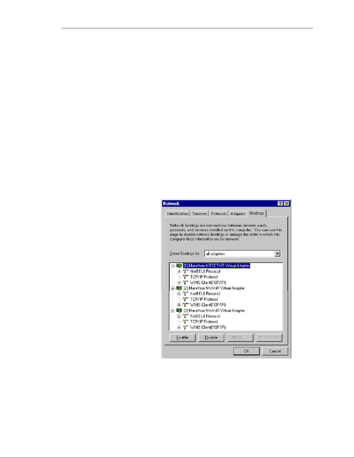
HP NetServer AA
CE Bindings
The adapter that works in conjunction with the public rail is the
MTCETHR Virtual adapter. This adapter is an Ethernet Redirector
and is “matched up” with the pair of adapters in the IOP, which are
bound to Ethernet Providers. To logically follow the path, the IOP,
being the system with a NIC directly on the LAN “provides”
network capabilities. The CE accesses this capability by
“redirecting” networking requests to the IOP. Still, there is no direct
communication from the CE to the IOP. The CE (ETHR) redirects
the request to the MIC, then through the SSDL, to the other MICs
that go to ETHP, and finally to the NIC in the IOPs.
There will be one MTCETHR virtual adapter for each public rail.
The list of the virtual adapters listed by Windows NT must match the
same order as the public rails on the IOP from top-to-bottom. They
do not have to occupy the same numerical position. For the purposes
of protocol settings, remember the first MTCETHR on the list in the
CE corresponds to the first public rail provider on each IOP. The
second instance of the MTCETHR on the CE corresponds with the
second rail on the IOP, and so on.
4-10
Each MTCETHR needs to have bound to it a traditional protocol that
logically makes sense when considering where its associated pair of
NICs in the IOP are cabled. If one pair of NICs is cabled to LAN
segment A via a switch, and another pair of NICs is cabled to LAN
Hewlett-Packard Company
Page 77

segment B via a different path, then the MTCETHRs need to reflect
that in their addressing.
The bindings to each MTCETHR consist of the appropriate
traditional network protocol.
Public Network to IOP to CE and Back.
Now that all of the protocols and bindings are in place, a “trace” of a
typical network request can be traced through the tuple.
1. Client traffic comes through the hub and is seen by all public
rails NICs for both IOPs that are on the local LAN segment
(assuming the same collision domain).
2. The public network card receives the traffic and immediately
passes it to the MIC. There is no analysis or breakdown of the
packet.
3. The packet is routed from the MIC to the SSDL for tuple 1.
4. The packet is received by the SSDL1 and prepared to be sent out
again.
Ch 4: Networking Explaineds
5. The SSDL will send the packet to the MICs of both CEs (the
path to CE2 is routed through SSDL2).
6. The CE’s virtual network adapter will receive the packet from
the MIC as if it were any other LAN traffic and its adapter
existed directly on the LAN. Whatever the network request, the
CE will generate responses to be sent through the MICs to the
IOPs.
Network Server Division
4-11
Page 78

HP NetServer AA
The Virtual Network
As mentioned earlier, each IOP and CE will have a virtual network
adapter for the purposes of creating an internal network in the array.
The virtual adapters are not associated with a physical network card.
Any use of the virtual network or traffic generated will be carried out
by the MICs and the SSDLs.
This network helps facilitate access to resources throughout the array
for maintenance purposes. It is not used to facilitate client traffic to
the LAN.
The virtual adapter is added to the list of adapters in Windows NT
for the CEs and the IOPs. And just like any other change in the
network properties in Windows NT, a reboot of NT is required to
enable the new adapter.
Virtual Network Configuration
The bindings for the CEs and IOPs are the same. It is simply the
traditional networking protocol to be used internally. The easiest
choice is NetBEUI, but TCP/IP may be used also. Just be aware that
there is not necessarily any value to using TCP/IP as this traffic is
never routed to another network or to a network client.
4-12
Hewlett-Packard Company
Page 79

Ch 4: Networking Explaineds
The remaining Marathon services are disabled for the virtual
adapters. There is no need for the Marathon Datagram Service, the
Marathon Ethernet Provider, and the MtcEtx driver.
The virtual adapters themselves are slightly different between the
CEs and the IOPs. The IOPS use a virtual provider (MtcVnP) and
the CEs use a virtual redirector (MtcVnR).
NOTE
The virtual network of CE to IOP1 and CE to IOP2 are
intentionally slow to avoid impacting MIC performance.
Network Server Division
4-13
Page 80

HP NetServer AA
Adding a Public Rail
After the HPAA system is operational, it may be decided that
another public rail is needed for whatever reason. It could be to
offload traffic from one public rail and have more aggregate
bandwidth, or it could be to service clients from a specific LAN
segment.
There are two choices of methods to add a public rail. One choice
places the emphasis on uptime and will only have one single system
reboot. At least one reboot is unavoidable due to Windows NT’s
requirements when adding network properties. The systems can be
prepared one at a time offline while the other systems remain online
until it is time to do one quick reboot. This method provides the
most availability, but it also involves what could be very lengthy
disk re-mirror operations.
The other choice is to schedule downtime and bring down the entire
system for the purposes of adding network cards and properties at
once. This avoids the lengthy re-mirroring process, but also means
the downtime could be upwards of one hour.
CAUTION
Do not mix versions of vendor LAN drivers for the NICs in
the IOP. The results may be unpredictable.
Working with a fully configured system
As mentioned earlier, a new system should arrive with all of the
networking preconfigured. In most environments, all that is left to
do is add the necessary networking protocols and settings that go
with the networking environment the HPAA system is installed.
Changing the networking properties is simple, unfortunately, so is
changing the wrong network properties. The most important
consideration to be made when working with a preconfigured system
is knowing what network properties to change. The following
guidelines will help in ensuring that the correct network properties
are changed and the HPAA system stays operational.
• Using Windows NT on the HPAA system is no different than a
single server implementation. If the network properties are
changed to the point that a “re-binding” occurs, Windows NT
must be rebooted for the changes to take effect.
4-14
• Server reboots of the CE operating system results in the HPAA
system being unavailable; plan accordingly.
• When trying to place the HPAA system on the network for
clients to access, it is the CE network properties that must be
changed, not the IOPs.
Hewlett-Packard Company
Page 81

Ch 4: Networking Explaineds
• The IOPs have the actual HP 10/100 TX driver installed and it is
listed in the network properties in Winodws NT on the IOP even
if the network cards are being redirected. Through the protocol
“Marathon Ethernet Provider” it establishes a relationship with a
MTCETHR virtual adapter on the CE.
• The CEs only have virtual adapters, one MTCETHR virtual
adapter exists for each public rail. Knowing which MTCETHR
adapter network protocols to modify is very important. For
example, if there are two public rails, one for subnet A and one
for subnet B, then there will be two MTCETHR virtual adapters
appearing in the network properties in Windows NT on the CE.
Which one of the MTCETHRs is for subnet B?
• The AA 4000 software does not know which network public
rail is cabled to subnet A and which one is cabled to subnet
B, and so on. It is up to the administrator to sort out.
• To match the physical cabling of the NICs representing the
public rail going to a subnet, to the actual protocol settings
on the CEs MTCETHR virtual adapter, look at the list of
network adapters in the Windows NT network properties on
both the CE and the IOP.
• Each Network adapter will have a number next to it, for
example [3]. Match the lowest adapter number for the HP
10/100 TX driver on the IOP, NOT counting the IOP Private
Link, to the lowest number of the MTCETHR virtual adapter
on the CE. Be aware that the numbers will not match most
of the time; [1] HPTX on the IOP may match with [3]
MTCETH on the CE if those are the two lowest numbers.
The MTCETHR network protocols and settings will be
carried out by its matching public rail.
Network Server Division
4-15
Page 82

Page 83

Chapter Five ~ System Upgrades
This chapter contains information on system upgrades for the HP AA
system based on the Endurance 4000 software from Marathon
Technologies.
Topics to be covered include:
• Adding hard disk space
• Adding SCSI Devices (HBA's, HP NetRAID)
• Upgrading the Marathon Software
• Updating/Patching Windows NT with Service Packs
• Updating NT Applications
Ch 5: System Upgrades
Network Server Division
5-1
Page 84

HP NetServer AA
Before Upgrading the HP AA System
Adding components to an existing HP AA Array is not as simple as
adding components to a standalone system. Many considerations
must be taken into account to ensure the array experiences no
downtime or at least the minimum downtime necessary for the
action.
One of the primary considerations when performing many system
upgrades is the decision to maximize uptime in lieu of a disk remirror or sacrifice the downtime to avoid a disk re-mirror.
Most system upgrades are easily be accomplished by bringing down
the system, making the changes and bringing the system back online.
If the customer can tolerate the downtime this is always the least
complicated method of upgrading system components. However,
many customer environments cannot tolerate the downtime. When
this occurs a methodical approach must be taken to ensure the least
amount of downtime is encountered.
In addition to downtime considerations, care must be taken to avoid
bringing down a functioning array by mis-configuring a device
during the upgrade process. The following sections will examine the
steps necessary to perform a variety of upgrade functions.
Becoming Familiar With the Array
When encountering a HP AA Array the configuration of the array
may not be familiar. It is critical that time be taken to become
acquainted with the array before beginning any system upgrades.
Even if the array is familiar it is prudent to pause for a few minutes
to reflect on the task to be accomplished, the steps to complete the
task and the effects of each of those steps on the availability of the
system.
A firm knowledge of the following is necessary before beginning
any upgrade.
• Identify the CEs and the IOPs.
• Know the display method used.
• The network configuration, including what adapters are
performing the role of IL and what adapters are public rail
adapters.
• The disk structure, including the location of IOP and CE boot
disks.
• What devices on the IOP are redirected.
5-2
• What devices are mirrored.
• What RAID structure is used.
Hewlett-Packard Company
Page 85

System Documentation
Ch 5: System Upgrades
The Endurance 4000 Installation Guide contains system
documentation tables designed to assist in the accumulation of data
necessary for installation and maintenance of the array. This
information is a good starting place when seeking to become familiar
with the array.
Once the array is properly documented the upgrade process can
begin. The key to success while upgrading in a high-availability
environment is to understand and anticipate the result of "every"
action taken on the array.
Before performing any upgrade ensure all system documentation,
user guides, installation guides, and software is available.
Remember, preparation is the key to success.
The following section documents the following system upgrade
tasks:
• Adding additional storage capacity
• Adding SCSI Devices such as HBA's and NetRAID Adapters
• Upgrading the Marathon Software
• Updating/Patching Windows NT with Service Packs
• Updating NT Applications
Network Server Division
5-3
Page 86

HP NetServer AA
Adding Additional Storage to the Array
During the life cycle of any Server system there is a high likelihood
the storage space will need to be increased. Adding storage to the
Endurance 4000 array is not a difficult process but there are a few
areas where care must be taken.
When adding storage to the Endurance 4000 the first question that
needs to be answered is "Can downtime be tolerated?" The answer
to this question will determine the procedures taken to add the
storage.
Can downtime be tolerated?
This operation requires each IOP to be rebooted twice and the CEs
once.
If downtime cannot be tolerated the upgrade process will take
significantly longer and will require two re-mirrors of the current
mirrored devices and one mirror of the new storage. Depending on
the amount of data, this can take a significant amount of time.
Software requirements:
If downtime can be tolerated, the Marathon Array can be taken
offline, the storage upgraded and the Array brought back online
without re-mirroring the current mirrored storage. The new storage
will still have to go through the initial mirroring operation.
The current configurations of the HP AA systems use the NetRAID
3Si controller for hardware RAID configurations. This controller,
whether it is embedded on the system board or in the form of an add
on SCSI board, requires software to configure RAID sets. This
software is the NetRAID Assistant. The NetRAID Assistant must be
installed on both IOPs. Configuration of the RAID sets can also be
accomplished using the Ctrl-M BIOS utility but the system must be
powered off and rebooted to this utility for this to work.
If the NetRAID Assistant is not already installed it will need to be
installed before additional drives added to the LH3 or LH4 can be
configured. Installing the NetRAID requires a reboot.
If the IOP is a HP LPr and is only using the internal SCSI drives, the
onboard Symbios controller is used and no software is required for
RAID configuration.
Document the present storage configuration
Before adding storage the current storage environment should be
documented. The following information was required during the
5-4
Hewlett-Packard Company
Page 87

installation of the Marathon array and should still be available. If
not, take the time to document it now:
• How many physical drives are present in the LH3 or LH4.
• What are the RAID set configurations for the drives?
• What logical drive is used for the IOP NOS?
• What logical drive is used for the CE?
• What other logical drive sets are redirected?
• What are the 4-digit SCSI ids of all logical drives?
Install the additional storage
Install the new drives into the disk enclosure and create the new
RAID sets using the NetRAID Assistant on IOP1 and IOP2. Make
sure to configure them exactly the same.
Caution should be taken here to not touch the other RAID sets that
are present. Doing this will cause damage to your data and may
possibly bring down the whole array. Simply use the NetRAID
Assistant to configure the new drives.
Ch 5: System Upgrades
Decision time
Reboot the IOP
At this point the question about downtime comes into play. A reboot
is required before Windows NT will recognize the newly created
drive.
If the whole system can be down for awhile, then it is best to down
the whole array at this time and restart both IOPs into offline mode
where configuration of the disks can be completed under NT Disk
Administrator.
If downtime cannot be tolerated then only one IOP can be brought
down at this time and rebooted into offline mode. Once this system
is complete, it can be brought back online. When this is done, a remirror will begin and must complete before the second IOP can be
brought down and booted to offline mode for the new disk to be
configured.
This is the first of two required reboots. This reboot is necessary for
Windows NT to recognize the new disks.
Configuring the new mirrored drive
Once the IOP is booted to offline mode, launch the Windows NT
Disk Administrator.
Network Server Division
5-5
Page 88

HP NetServer AA
The Disk Administrator is used to create the partitions on the new
drive. Make sure to create the special Marathon partition at the end
of the drive. Do not format this partition or assign a drive letter to
this partition.
All partitions other than the Marathon partition must be formatted
NTFS.
If the other IOP is not being configured at this time make sure to
document the partition structure for duplication on the other IOP.
Format NTFS Marathon Partition
Determine the 4 digit SCSI Identifier
Marathon mirrored devices are mirrored according to the 4 digit
SCSI identifier. This identifier is located in the Registry.
The location in the Registry is:
HKEY_LOCAL_MACHINE
HARDWARE
See the figure below:
DEVICE MAP
SCSI
5-6
Hewlett-Packard Company
Page 89

Ch 5: System Upgrades
This is the point where previous documentation comes in handy. By
comparing the previous 4 digit SCSI IDs with the IDs displayed in
the Registry it should be easy to pick out the new ID.
Record the new ID for future use. Make sure the other IOP has the
same 4 digit SCSI for the new device.
Modify the Marathon configuration on IOP1 and IOP2
Once the 4 digit SCSI ID has been acquired the Marathon
Configuration Utility can be run to add the new mirrored storage.
Launch the Configuration Utility.
Click the Disk Drives and click the Add button to add the new
storage. This is the point where the 4 digit SCSI ID must be entered.
Before entering this information make sure to verify it is the same on
both IOPs. Mismatches here could have catastrophic results on the
Array.
The figure below shows the Marathon Configuration with one disk
drive mirrored and redirected. The following figure shows the
display after the additional drive has been added to the list of
mirrored redirected devices.
Network Server Division
5-7
Page 90

HP NetServer AA
r
Before
adding the
additional
storage
Afte
adding the
storage.
5-8
Hewlett-Packard Company
Page 91

The best method for modifying the Marathon configuration is to
make the modifications on one IOP, save it and copy to the other
IOP.
Reboot the array
At this point everything is ready. A final reboot of the entire array is
necessary for the disks to be redirected to the CEs.
Confirm the new drives on the CE
Open Windows Explorer and examine the new drive.
Adding SCSI Devices (HBA's, HP NetRAID)
Since this operation requires the installation of hardware the IOP
must be brought down. Once again the decision must be made to
bring down the whole array for a period of time and forgo any remirroring operations or bring down the IOPs one at a time and suffer
the re-mirror operations.
Ch 5: System Upgrades
When adding SCSI devices care must be taken not to affect the
present 4 digit SCSI ID settings of the existing devices. Adding a
SCSI device in a higher order on the SCSI bus scan will cause lower
order devices to shift the 4 digit SCSI ID settings. If this occurs the
Marathon Configuration will be corrupt and will have to be
recreated.
It is not necessary to install duplicate devices in both IOPs unless
those devices will be used to control mirrored disks, as in the case of
a NetRAID controller. It is okay to add an HBA for backup
purposes without adding a matching one in the other IOP. Once
again, care should be taken to ensure all existing mirrored device 4
digit SCSI IDs are not affected by the addition of the device.
Network Server Division
5-9
Page 92

HP NetServer AA
The following table should be followed when installing additional
devices.
Type NetServer PCI Card 1st Choice Other Choices
CE LPr
IOP LH 3/4r Or SCSI HBA (2)Slot 1 Slot 3,4
MIC Slot 1
RMC Slot 2
MIC Slot 8
NetRAID-3Si (1) Slot 7 Slot 1
NetRAID-3Si (2) Slot 1 Slot 2,3
Or SCSI HBA (1)Slot 7 Slot 1,4,5,6
NIC Public (1) Slot 2 Slot 3,4
NIC Public (2) Slot 3
NIC Public (3) Slot 4
NIC IOP Link Slot 5
RMC Slot 6
Slot 3 if only 1
public NIC
5-10
Hewlett-Packard Company
Page 93

Upgrading the Marathon Software
If the Marathon software needs to be upgraded or “patched”, there
are several considerations.
Before upgrading Marathon software, make sure that:
• The Marathon CD that contains the new version of software is
available
• An MTC diskette made using the new Marathon software is done
• All mirror copies are done.
• There is up to 24 MB of free space on the each IOP and CE
system drive.
• Any necessary backups are completed
• An appropriate amount of downtime (normally less than one
hour) to complete the upgrade procedure has been scheduled. At
that time, continue with Upgrading Marathon Software on the
CE Operating System.
Ch 5: System Upgrades
• Additionally, if the array to be upgraded includes any Marathon
hot fixes, check the Endurance 4000 Release Notes to determine
whether the upgrade that you are applying includes support for
that hot fix. If it does not, contact HP Support.
• Do not apply hot fixes distributed for a previous version of
Endurance 4000 software to Endurance 4000 Release 2.2.
Be sure to review the release notes of any Marathon patch or upgrade
thoroughly before starting any of the procedures. Because the
detailed steps may change in any given release, the following is an
overview of what an upgrade process will be like:
In general, the CEs will be upgraded first and will include the
installation of the new documentation, the installation of the latest
VnR drivers and lastly the shutting down of the CEs. By shutting
down the CEs a disk re-mirror can be avoided.
Next, the IOPs are upgraded one at a time including adding the latest
Marathon networking services and ending with the shutting down of
the IOPs.
WARNING
When upgrading the Marathon software on the IOPs when
the screen calls for the upgrade options, it is critical to
select Restore Original Installation Parameters. Selecting
Preserve only applies to special cases and may not work on
some systems.
Network Server Division
Now that all nodes are off, the MICs can be flashed with the latest
MTCflash utility that will be on the upgrade CD.
5-11
Page 94

HP NetServer AA
Upon completion of flashing all MICs, the array can then be
restarted and the Marathon Manager can be used to verify the array
is completely operational.
Upgrading Marathon software on the CE Operating System
Considerations for upgrading the CE Operating System:
• A CDROM must be available to the CE either by way of a
redirected IOP device or a shared IOP device.
• The Marathon installation procedure will start automatically
unless the auto launch feature has been disabled on the CE. If
this is the case, open Explorer, access the CDROM and launch
setup.exe.
• Follow the instructions displayed on the screen and configure the
Endurance 4000 for your environment.
• During installation, make sure the defaults are chosen for the
following items:
• Kit Number
• Endurance System Setup
• CE installation
• Restore Original Installation Parameters
• Install the Endurance 4000 online documentation.
• Install the Virtual Network Redirector using the Network
Neighborhood. Refer to the section on Networking or the User
Guide for details on the Bindings.
• When prompted to reboot answer No. You should never allow
NT to reboot or power off a system in the Array. Use the
Marathon Manager to power off the CEs. Performing the actions
in this manner will prevent a re-mirror.
• When the CEs reboot, power them off until the IOP upgrade is
finished.
Upgrading Marathon Software on Each IOP
Considerations for upgrading the Marathon Software on the IOP.
• The IOPs should be shutdown and restarted in Offline Marathon
Mode to upgrade the software.
5-12
• Use the Marathon Manger to shutdown IOPs.
• Launch the Marathon setup.exe from the Marathon CDROM.
• Follow the instructions displayed on the screen, configure the
Endurance 4000 for your environment. During installation, make
sure that you choose the defaults, including:
Hewlett-Packard Company
Page 95

Ch 5: System Upgrades
• Install Endurance Software
• Kit Number
• IOP installation
• Restore Original Installation Parameters
• IOP in TUPLEx (for IOP1, choose TUPLE1; for IOP2,
choose TUPLE2)
• Destination directory for IOP Maintenance Mode
• DoNot Edit Configuration
• Install the Endurance 4000 online documentation.
• If you are running Windows NT Server on the IOP, configure the
Network, Service, Server, and Properties to Maximize for
Network Performance.
• Determine whether the Marathon Datagram Service (MtcDgs) is
installed on your server.
If not, install and bind it using the procedures outlined in the
networking setting.
• Install the Virtual Network Provider on each IOP.
• Reboot the IOP and CE operating systems. Upon reboot, the
Virtual Network is enabled on the Endurance 4000 server.
Use the MTCFlash diskette to Flash the MICs on the IOPs.
WARNING
• Boot the IOPs to Online Marathon mode. Examine the
Marathon Manger while the systems boot to confirm the IOP
status of the IOPs is online.
Running MTCFlash on each CE
• To complete the Marathon software upgrade, you must run
MTCFLASH on both CEs.
• You will have to temporarily attach a keyboard to the CEs to
complete this task.
Make sure to complete the flash of the MIC by completely
powering off the NetServer using the power switch. Do not
use the reset button or issue a Ctrl-Alt-Del reboot.
Network Server Division
5-13
Page 96

HP NetServer AA
Verifying the Upgrade
After upgrading Marathon software, use Marathon Manager to make
sure that:
• All Endurance components transition to active, online or standby
(either bright green or dark green).
• Any required mirror set copies are in progress or have completed
successfully.
• The revision information (displayed using View->Revision
Level) is identical to the revision information documented in the
Endurance 4000 Release Notes for newly installed software.
If you are have difficulty installing the upgrade:
• Verify that the Marathon Datagram Service (MtcDgs) is properly
installed and bound.
• Verify that the Marathon MtcVnP Virtual Adapter is properly
installed.
• Make sure that all four MICs have been flashed using the new
version of Marathon software.
5-14
Hewlett-Packard Company
Page 97

Upgrading an Installed System to an SMP IOP System
Having dual processors in the IOP is overkill for the array workload.
The IOP is responsible for the I/O activities which are not processor
intensive.
During installation it is better to install the multi-processor kernel
even if a single processor will be used. This will not affect the
installation of the Marathon software and will eliminate the need to
upgrade the kernel when an additional processor is added.
If the need arises for upgrading a system from a single processor
kernel to a multi-processor kernel, the User Guide contains detailed
steps to accomplish this task.
Other Upgrade and Downgrade Options
There are three other upgrade and downgrade options in the
Endurance User Guide. These tasks would be required in only the
rarest circumstances and detailed steps are available in the User
Guide.
Ch 5: System Upgrades
Network Server Division
5-15
Page 98

HP NetServer AA
Updating/Patching Windows NT with Service Packs
The HP AA array is able to have different Windows NT Service
Packs on each system of the array. The only consideration is that the
Service Pack must be supported. Examine the Readme file located
on the Marathon CDROM for the supported Support Packs.
One reboot is required for a Service Pack upgrade of all systems. If
only the IOPs will be upgraded they can be done one at a time with
re-mirrors in between. If all systems of the Array will be upgraded it
is best to upgrade the CE and IOPs and issue a Marathon System
Reboot.
For the CE Operating System
To add a Windows NT Service Pack to the CE operating system:
• Install Windows NT Service Pack software.
• When prompted, do not reboot Windows NT.
• Using the Marathon CD, reinstall Marathon software, selecting
the CE installation option.
• Schedule an appropriate time to reboot the CE operating system.
For the IOP Operating System
To add a Windows NT Service Pack to an IOP:
• Using the Marathon Configuration Utility, save the current
configuration to a file.
• Install Windows NT Service Pack software.
• When prompted, do not reboot Windows NT.
• Using the Marathon CD, reinstall Marathon software, selecting
the IOP installation option.
• When prompted, open the Marathon Configuration Utility.
• Open and commit the file that you saved in Step 1
• Use the Marathon Manager to reboot the IOP.
5-16
Hewlett-Packard Company
Page 99

Updating NT Applications
The key to upgrading NT Applications is to make sure the upgrade is
performed on the proper machine. All array applications run on the
CE operating system. Generally, applications are upgraded using a
CDROM. Since the CE does not have it's own CDROM, a
redirected CDROM must be used. An alternative to this method is to
use a Network Shared CDROM.
Ch 5: System Upgrades
ΝΟΤΕ
ΝΟΤΕ
ΝΟΤΕΝΟΤΕ
Upgrading of any application in a high availability should be
preceded by testing to ensure the stability of the upgrade.
If the application upgrade requires a system reboot then the CE NOS
will have to be rebooted. Do not allow NT to reboot the CEs.
Instead, use the Marathon Manger to issue a reboot sequence for the
CEs.
Network Server Division
5-17
Page 100

 Loading...